59
Boiler Installation Presented by: North Dakota Boiler Inspection Program

Boiler Installation
Presented by:North Dakota Boiler Inspection Program

Department of Environmental QualityBoiler Inspection Program918 E Divide Ave, 4th FloorBismarck, ND 58501
Mailing Address:

Bismarck: Fargo:Trevor S Seime, Chief Inspector Nicolle Fowler, Deputy Inspector701-220-4723 cell 701-541-2113 [email protected] [email protected]
Renee Skraba, Deputy Inspector Vincent Rolczynski, Deputy Inspector 701-400-1043 cell 701-781-0528 cell [email protected] [email protected]
Bismarck Fax: 701-328-5200 Website: https://deq.nd.gov/Director/BIP/
Contact Us:

Where do we have jurisdiction? Any size of boiler in a six-unit apartment or
larger. Any size of boiler in buildings where the public
is invited. Exemptions are federally controlled buildings and farm use buildings.
Any water heater or pool heater larger than 200,000 BTU/HR input at above locations.
Antique/historical boilers at public shows.

Introduction:Focus on hot water heating systems.Clearances – make a good plan from the start
of the installation.Requirements and controls for all boilers.Other boiler installation tips.Water heater and pool heater installs. Installer form – a requirement.

Boiler Clearances: Heating boilers shall have a minimum distance of at
least 36” between all sides of the heating boiler and adjacent walls, structures, or other equipment.
Alternative clearances in accordance with the manufacturer’s service and maintenance recommendations are subject to acceptance by the Chief Inspector.
If it will not fit, it cannot be installed. It will not be easier to obtain forgiveness after the fact
than to get permission beforehand.

Nice Installation vs. Clearance Problems
Room to operate and service the boiler…
Hard to get around the equipment...

Boiler Stamping:Steel, stainless steel, and electric boilers
must have an ASME stamp and be National Board registered.
Cast iron and cast aluminum boilers must have an ASME stamp. (NB registration not required for cast.)

Some boiler designs not acceptable: Code stamped boilers, but some not always acceptable to State due
to internal piping and control issues.
***Please call us before installing a boiler you have not used before as new products come on the market all the time and may not meet State Boiler Code even with the correct ASME and National Board stamping.

Boiler Requirements and Controls:1. Two temperature controls – one with manual reset and lockout2. Testable low-water cut off with manual reset and lockout, or flow switch 3. Expansion tank with stop valve 4. Safety relief valve5. Temperature and pressure gauge6. Isolation valves 7. Drain valve8. Electrical switch 9. E-stop (required over 400,000 BTU/HR input)10. Makeup water system – not always required (RPZ, regulator with bypass, and feed line stop valve)11. Venting12. Combustion Air13. Recommend condensate neutralizer kit for all high efficiency appliance
exhaust drains

1. Two Temperature Controls – one with manual resetMany of the operating and manual reset high limit controls are factory installed and internal to the boiler, if the temp setting are correct, no other controls are required. High efficiency stainless steel boilers have
a maximum allowable working temp (MAWT) of 200F or 210F
Cast aluminum MAWT 200F
Cast iron MAWT 240F or 250F
Steel boilers MAWT 250F
Copper fin tube boilers MAWT 210-250F
The dial range of your manual reset high limit control cannot exceed the MAWT of the boiler.
The lowest MAWT is the determining factor for setting the MRHL control on all boilers in the system.
The Honeywell L4006E1125/U or equivalent with a dial range of 100-200F is the correct control for high efficiency boilers that require an external control.

2. Low Water Protection…Low Water Fuel Cutoff vs. Flow Switch Low water fuel cutoff is required
for cast iron, cast aluminum, fire tube boilers and some electric boilers:
The low water fuel cutoff must be testable and have a manual reset and lockout (per ASME CSD-1).
Must be installed on the boiler proper above the safe water line or on the boiler supply outlet piping (hot side) before the first isolation valve. May not be installed beneath the boiler.
Flow switch is required for water tube boilers, fired coil boilers, pool heaters and some electric boilers:
Consideration should be made to match the flow rate and piping size to the type of flow switch.
Must be installed on the primary boiler loop in primary/secondary piping.
Recommend to install inside the boiler isolations valves – easier to service.
Test once installed to verify it shuts down the boiler.

2a. Common Fire Tube and Water Tube boilers:
Fire Tube – Low Water Cutoff Water Tube – Flow Switch

2b. Low Water Fuel Cutoff Examples:Correct install for fire tube vertical tube:
Correct install for cast iron:

2c. Flow Switch Examples:Correct installation water tube boiler: Correct installation electric boiler:

2d. Electric Boilers and Low Water Protection:Low water protection:
For vertical element designs (i.e. Electro Industries, Thermolec) a low water fuel cutoff is acceptable.
For horizontal element designs (i.e. Slant Fin Monitron) a flow switch is required by the manufacturer.
For very large electric boilers the low water protection is usually built in and determined by the manufacturer.

3. Expansion Tank with Stop ValveAll expansion tanks require a stop valve between the tank and the system, expansion tanks must be installed on the supply (outlet-hot) side of the boiler.
ASME expansion tank – a stamping plate is welded to the tank with a code symbol and nameplate data.
Non-ASME expansion tank – typically a paper or sticker tag on the tank showing the tank information.
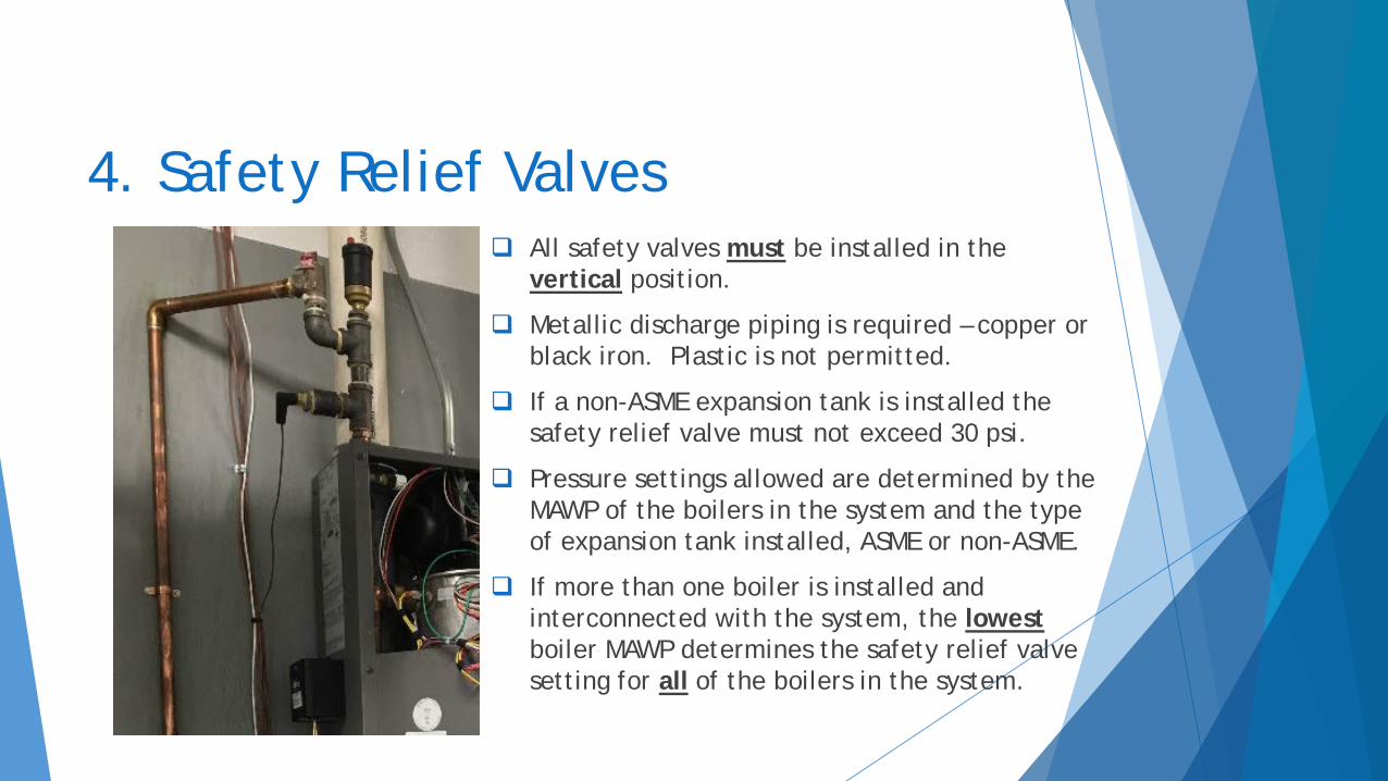
4. Safety Relief Valves All safety valves must be installed in the
vertical position.
Metallic discharge piping is required – copper or black iron. Plastic is not permitted.
If a non-ASME expansion tank is installed the safety relief valve must not exceed 30 psi.
Pressure settings allowed are determined by the MAWP of the boilers in the system and the type of expansion tank installed, ASME or non-ASME.
If more than one boiler is installed and interconnected with the system, the lowestboiler MAWP determines the safety relief valve setting for all of the boilers in the system.

5. Pressure/Temperature Gauge The dial range of the pressure
gauge must be 1 ½ to 3 ½ times the setting of the safety relief valve set pressure.
If the boiler has a 30 psi relief valve the dial range of the gauge is required to be a minimum of 0-45 psi and a maximum of 0-105 psi.
The pressure/temperature gauge must be installed on the boiler proper or on the outlet piping before the first isolation valve.
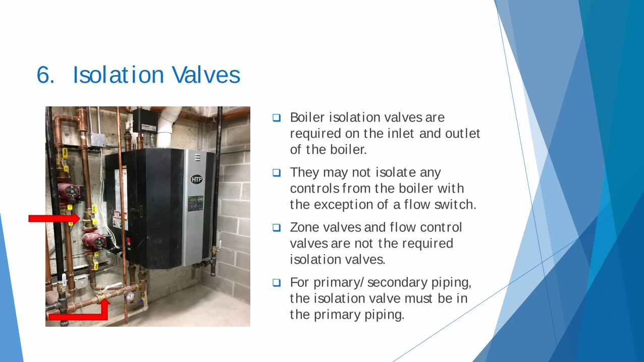
6. Isolation Valves
Boiler isolation valves are required on the inlet and outlet of the boiler.
They may not isolate any controls from the boiler with the exception of a flow switch.
Zone valves and flow control valves are not the required isolation valves.
For primary/secondary piping, the isolation valve must be in the primary piping.
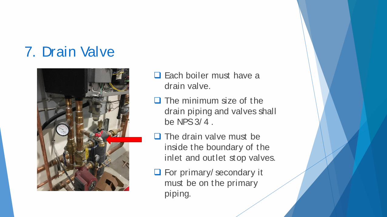
7. Drain Valve Each boiler must have a
drain valve.
The minimum size of the drain piping and valves shall be NPS 3/4 .
The drain valve must be inside the boundary of the inlet and outlet stop valves.
For primary/secondary it must be on the primary piping.

8. Electrical Switch
Every boiler must have an on/off electrical switch.
If there is not a switch factory installed on the boiler, a switch must be installed that is easily accessible to reach from the floor.
On/off switches on the ceiling are not accessible.

9. Emergency Stop –for all boilers over 400,000 BTU/HR input
A manually operated emergency shutoff switch must be located just outside the boiler room door and marked for easy identification. Some exceptions apply with approval.
Consideration should be given to safeguard against tampering.
If the boiler room door is on the building exterior, the switch must be located just inside the door.
The emergency switch or circuit breaker must disconnect all power to the burner controls.
10. Makeup Water System – Automatic Water Feeder On, Off or Not Installed A boiler needs low-water protection. A low water cutoff or
flow switch satisfy that requirement for new boilers. No feed water regulator is required, and it may be turned off if desired.
Older boilers – low-water cutoffs were first required in 1994. If the boiler is installed prior to 1994 and does not have testable low water protection a feed water regulator is required and it must be left on.
Broken feed lines require, at a minimum, a vacuum breaker on the city water side. (See Plumbing Code)
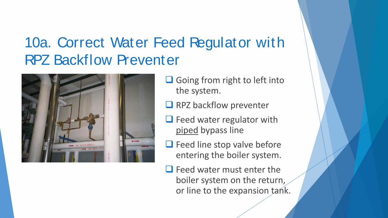
10a. Correct Water Feed Regulator with RPZ Backflow Preventer
Going from right to left into the system.
RPZ backflow preventer Feed water regulator with
piped bypass line Feed line stop valve before
entering the boiler system. Feed water must enter the
boiler system on the return, or line to the expansion tank.

11. Venting – General Information Type B chimneys are not to be used for solid fuel or
oil. Solid fuel and gas or oil equipment can not vent to
the same venting system. Single-wall metal venting must be at least 6” from
combustible material for gas. For common venting, you must upsize 50% of the
area for any additional vent. Horizontal piping must have at least a 2% up slope. Modifying vent hoods to fit is not allowed. Consult local jurisdiction if necessary.

12. Combustion Air Most high efficiency boilers have combustion air directly
piped from the outside. Many conventional replacement and new boiler installations
have incorrect combustion air. Combustion air is figured at 1 sq. in. per 4,000 BTU/HR input
– two openings required, or 1 sq. in. per 3,000 BTU/HR of input – one opening.
Professionally designed combustion air recommended for any other design.
All dampers, louvers or supply fans must be interlocked with the burner in a fail-safe manner.
Mechanical air exhausting must also be considered when sizing combustion air.

13. Condensate Neutralizer Kit –recommended for all high efficiency boilers and water heaters
Washes away surrounding concrete, metal drains and piping. Installed 3 years ago.
Condensate neutralizer – one example

Other Boiler Installation Tips…..

Replacement Boilers Controls and piping must be updated. The replacement boilers
must be installed to current code and any re-used controls must meet current code.
Clearances must meet the new boiler listing and state boiler code.
You cannot exchange like for like and not make updates to the system.
Considerations for old systems and new boilers
not all high efficiency boilers are tolerant of old piping and dirty systems – cleaners and filters may be needed
some new boilers require special water treatment

Shop Installation Boilers installed in a shop
where vehicles can be stored must have the burner at least 18” off the floor.
If the boiler is installed in a mechanical room with access from the shop it must still be 18” off the floor.
This includes sealed combustion boilers.

Off Peak or Dual-Fuel SystemsWe require each boiler to be installed such that
either one can operate independent of the other.
We require parallel installation. Boilers that flow through each other in series are not permitted. If a flow through design is desired, alternate piping may be installed as bypass.
Adding a new boiler to an old system may require isolation valves to be added to the old boiler which was previously “grandfathered” without valves.

Expansion tanks and air eliminators This is the typical
installation of an air eliminator.
The air eliminator must be installed on the supply (outlet-hot) side of the boiler.
It must be installed on the low pressure side of the circulating pump.
The expansion tank should be installed on the bottom connection of the air eliminator.
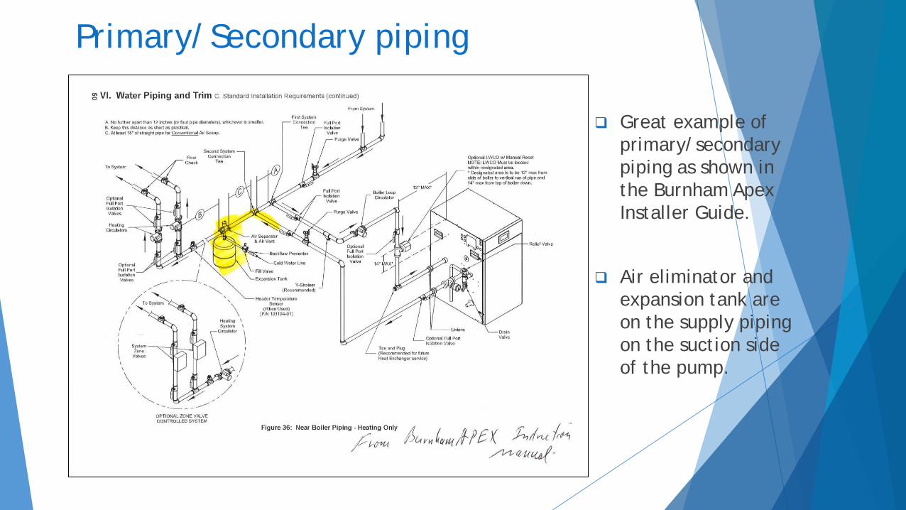
Primary/Secondary piping
Great example of primary/secondary piping as shown in the Burnham Apex Installer Guide.
Air eliminator and expansion tank are on the supply piping on the suction side of the pump.

E-stop required if boiler exceeds 400,000 BTU/HR

E-stop required if any single boiler exceeds 400,000 BTU/HR


Hot Water Supply Boilers cannot be used for Space Heating or Dual-Use is not allowed
Using a storage water heater or other hot water supply boiler (HLW stamp) for space heating, or for dual-use domestic and sanitary purposes and space heating, is not allowed.
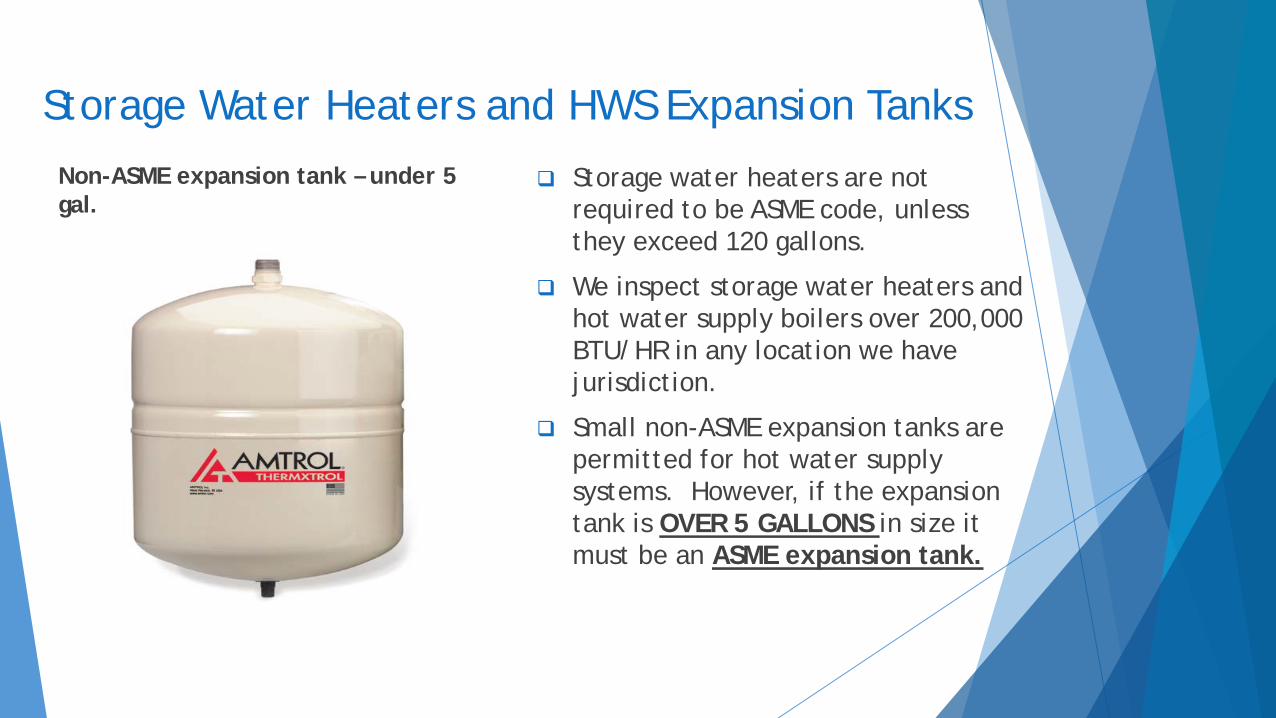
Storage Water Heaters and HWS Expansion TanksNon-ASME expansion tank – under 5 gal.
Storage water heaters are not required to be ASME code, unless they exceed 120 gallons.
We inspect storage water heaters and hot water supply boilers over 200,000 BTU/HR in any location we have jurisdiction.
Small non-ASME expansion tanks are permitted for hot water supply systems. However, if the expansion tank is OVER 5 GALLONS in size it must be an ASME expansion tank.

Pool HeatersPool heaters smaller than 200,000 BTU/HR
input do not fall under our jurisdiction.Pool heaters must be ASME constructed with
an “H” or “HLW” designation and be National Board registered.
Pool heaters with stop valves installed between the boiler and pool must have a flow switch.

Matrix and Installer Report…

Boiler Matrix
Great tool, notes on the back of the matrix.

Boiler or Water Heater Installation Report
This form is now a requirement, not an option, and must be filed with the Chief Boiler Inspector. Verbal reports are nice, but do not meet the requirements of Code. This form is now fillable and available on our website.
The completed form must be mailed, scanned, emailed or faxed to the Chief Inspector.

What Not To Do…
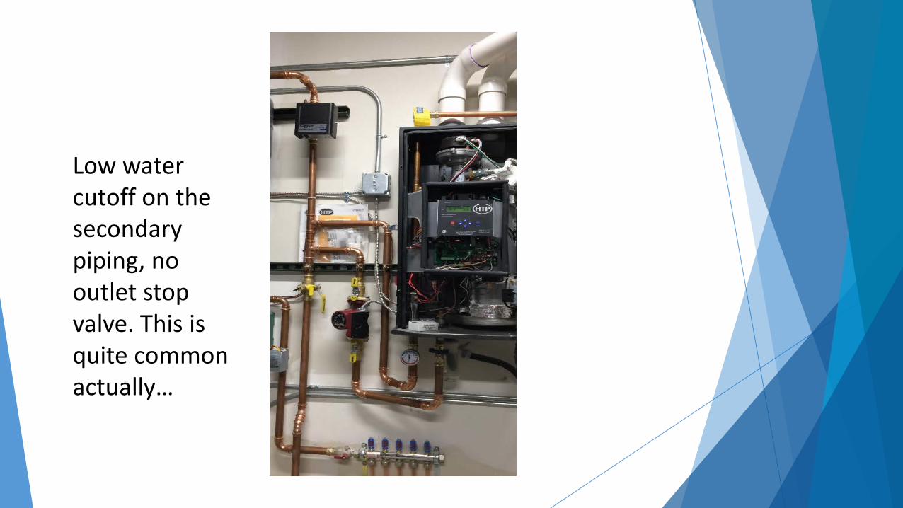
Low water cutoff on the secondary piping, no outlet stop valve. This is quite common actually…

Safety relief valve inside the boiler cover where the manual reset high limit goes on this boiler, safety relief valve horizontal, no low water cutoff… and many more…

Safety relief valve in the feed line?
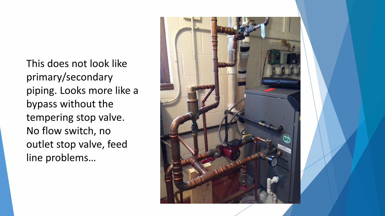
This does not look like primary/secondary piping. Looks more like a bypass without the tempering stop valve. No flow switch, no outlet stop valve, feed line problems…

Needs service or new install…

Residential low water fuel cutoff – has test, but no manual reset.

This is a steam boiler, but we see the same problem on hot water. This safety valve is reduced in size –boiler tapping is about ¾” or 1” and then upsizes to install large valve. Valve cannot discharge full capacity due to reduction. Installed horizontally also…

Nice install, but low water fuel cutoff on return instead of supply…

Wrong low water fuel cutoff and wrong location

No expansion tank stop valve

Isolated both low water and manual reset high limit from boiler

Feed line problems…no feed line stop valve or piped bypass around regulator

Summary Many items must be taken into
consideration on every boiler installation.Use Manufacturer’s Installation Manual to
help organize process and what you need.Call with any questions prior to starting an
installation.

QUESTIONS?Website: https://deq.nd.govClick on Office of the DirectorClick on Boiler Inspection Program

Thank You


