FlexTech Utility Circulating Fluidized Bed [CFB] Boiler 2-6 FiCirc Industrial Fluidized Bed [FB] Boiler 7-10 Chemical Recovery Boiler [CRU] 8-13 Industrial VU-40, VU-60, VP and A Boilers 14-17 Heat Recovery Steam Generators [HRSG] 18-21 Pulverized Coal Fired Utility Boiler 22-25 Power Plant Emissions 26-29
Figure 1: Chemistry Summary for CFB Combustion .............................................3 Figure 2: Gilbert Unit No. 3 Circulating Fluidized Bed Boiler ................................5 Figure 3: Gilbert Unit No. 3 CFB Environmental and Ash Handling Systems......6 Figure 4: Redbank Station FiCirc Fluid Bed Boiler ..............................................10 Figure 5: Somerset Mill Chemical Recovery Boiler..............................................13 Figure 6: Typical VU-40 Boiler................................................................................15 Figure 7: Typical ‘VP’ Boiler ...................................................................................16 Figure 8: Typical ‘A’ Boiler .....................................................................................16 Figure 9: Typical VU-60 Boiler – Front Fired.........................................................17 Figure 10: Typical VU-60 Boiler – Tangentially Fired ............................................17 Figure 11: Heat Recovery Steam Generator Temperature Profile........................18 Figure 12: Kyrene Station HRSG.............................................................................21 Figure 13: Typical RPS Pulverizer ..........................................................................23 Figure 14: Typical TFS-2000 Low NOx Burner.......................................................23 Figure 15: Crawford Unit No. 8 Pulverized Coal Fired Utility Boiler ....................25 Figure 16: Weighted Wire Frame Precipitator........................................................27 Figure 17: Wet Flue Gas Desulfurization System ..................................................28
Greek Steam Jet Boiler Circa 2600 B.C.
BOILER ARRANGEMENT QUICK REFERENCE
This document is intended for use only by employees of ALSTOM Power, Inc.’s Power Service Segment. All information herein is considered strictly confidential. This document is supplied with the understanding that it will be held confidentially and will not be disclosed or offered to
third parties without prior written consent of ALSTOM Power, Inc.
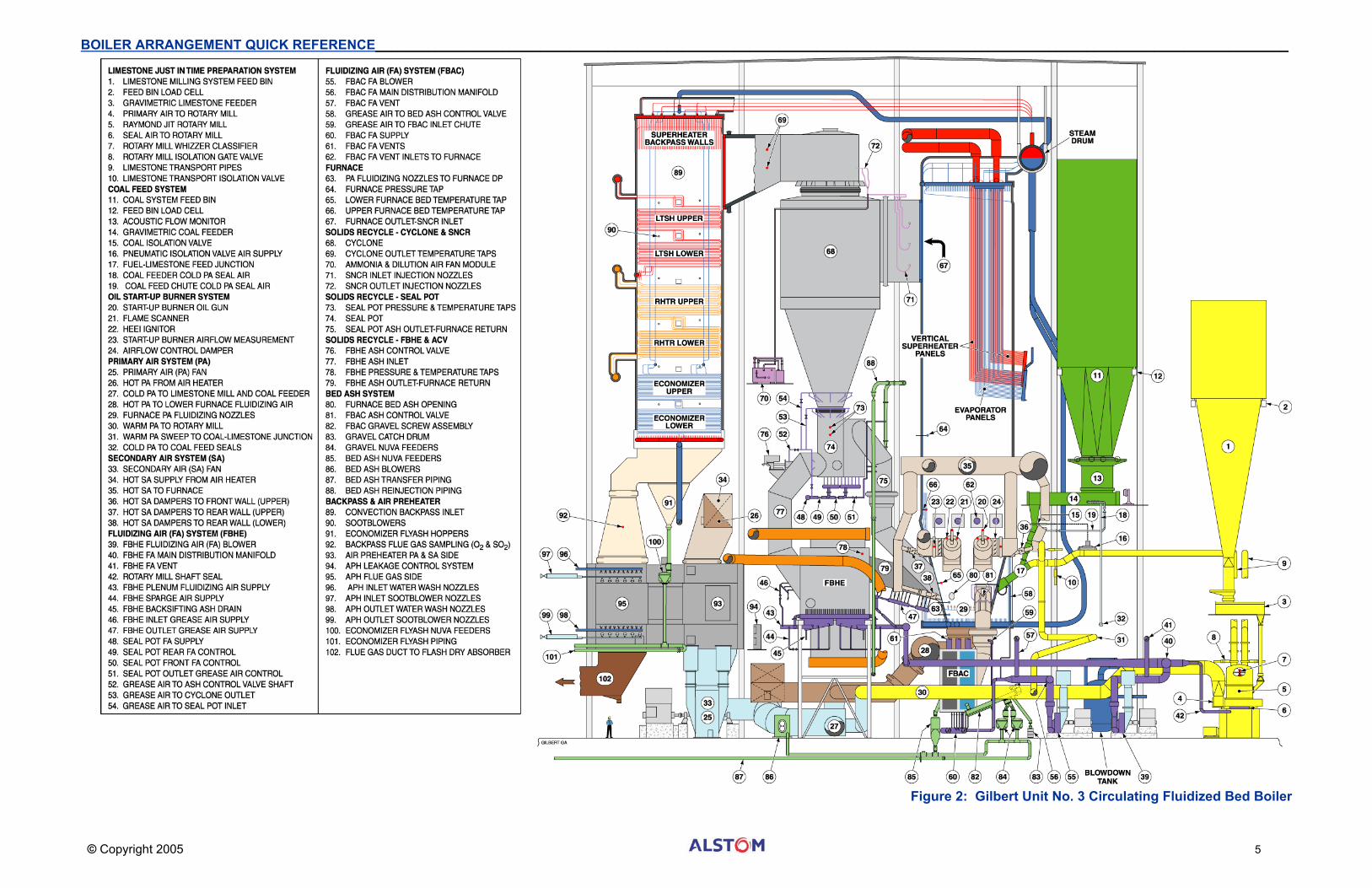
FlexTech UTILITY CIRCULATING FLUIDIZED BED BOILERS Gilbert Station Unit No. 3 Circulating Fluidized Bed [CFB] Boiler
The following technology and arrangement summary provides fundamental design and layout information for the present ALSTOM Power offering of a modern utility CFB boiler burning high sulfur, high ash coal. The information is based on Contract No. 00701. For additional information on Fluidized Bed technology refer to ‘Combustion Fossil Power’ text Fourth Edition [1991] Chapter 9.
Source of Fossil Fuel CFB technology is unique in its ability to efficiently use any fossil fuel from refinery waste coke, coal, all the way down to very low quality ‘waste’ fossil fuel. Gilbert Unit No. 3 was designed to handle a fairly wide range of hard Eastern coal. The design target fuel flow is 240,093 lb/hr with 20% ash, and 4.5% sulfur at 10,400 Btu/lb. Each of the eight gravimetric coal feeders provided is capable of handling 38,900 lb/hr.
Source of Sulfur Capturing Sorbent [Limestone] Limestone is a plentiful mineral throughout the world; a remnant of the first fossil records dating back 545 million years ago to a period known as the Cambrian explosion. The Gilbert Project can utilize local limestone mines. This supply of limestone serves as the sulfur capturing sorbent. Limestone, which consists primarily of calcium carbonate (CaCO3), allows 80% of the sulfur emissions to be captured within the fluidized bed during the combustion process. Additionally, flyash, heavy with burnt lime (CaO), is captured and injected in an ALSTOM Power designed environmental backend system Flash Dry Absorber (FDA) that will augment the CFB sulfur reduction capability. Gilbert utilizes two ALSTOM Power Raymond Limestone Rotary Mill Systems, each capable of 56,000 lb/hr. One mill in service provides sufficient volume for even the worst high sulfur coal. For more on the subject of Power Plant Emissions, refer to page 26.
Preparation of Coal and Limestone Distribution of particle size is critical for effective carbon burnout relative to the type of combustion process employed (Table below). While fossil fuel can be burned in small chunks on a stoker, most large coal-fired utility stations burn pulverized coal in suspension. For a standard pulverized coal-fired utility boiler, the coal is ground to a face-powder consistency and is pneumatically transported through piping from the pulverizer to the furnace. The powder consistency produces particle sizes that are quickly heated, ignited and burned in the furnace.
Combustion Process
Passes Through 400 Mesh
Passes Through 200 Mesh
Passes Through 60 Mesh
Passes Through 30 Mesh
Passes Through 3/8”
Top Size Passes Through 1”
Spreader Stoker 0% 1% 3% 5% 30% 60-80%
Pulverized Coal 55% 75% 98.5% 99% 100% 100%
CFB Coal Dust 2% 4% 12% 25% 99% 100%
CFB Limestone 3% 4% 8% 12% 55% 94%
CFB Bed Ash 1.5% 3% 35% 90% 0% 0%
Fuel Particle Sizes per Furnace System Design
CFB boilers do not require the same level of fineness. The coal and limestone are crushed to sand and gravel size particles. The previous Table shows the size particles that turbulently churn within the heart of the CFB combustion process.
Fuel and Sorbent Feed Furnace Injection The solid fuel feed system delivers the sand and gravel size coal particles that provide the main CFB heat source. This system consists of the following components: fuel silos, fuel silo outlet shutoff valves, fuel flow monitors, gravimetric feeders, fuel feed isolation valves, fuel feed chutes, and fuel feed nozzles. The limestone milling system consists of the following components: gravimetric feeders, Raymond rotary mill (crusher) with a dynamic classifier, hot and cold primary air supply ducts, transport and seal piping, isolation valves and a parallel primary air purge supply. The limestone is given its final processing only seconds before delivery into the furnace. For this reason, the system is referred to as a ‘Just-In-Time’, or JIT, delivery system.
Crushed coal and sorbent (limestone) are introduced together into the furnace, which has been preheated to a minimum operating temperature with light oil for the start-up burners. It can be calculated that 2.2065 x 10⁹ Btu of heat must be converted to steam to drive the 290 Mw (gross) turbine-generator set. Assuming a maximum 40 Mw of auxiliary service power, the net output will be ~260 Mw. This CFB boiler design is ~88% efficient. Therefore, assuming a steady state of flow exists, 2.497 x 10⁹ Btu of chemical energy must be delivered per hour to obtain this output. Assuming an average coal supply quality of 10,400 Btu/lb, coal must be fed at a rate of 240,093 lb/hr, which is ~120 tons per hour.
In order for the limestone to fully absorb the sulfur, approximately 2.0 to 2.2 Ca/S ratio is needed. Viewed at a molecular level, and based on contract specifications, it is assumed that limestone is 94% calcium carbonate (CaCO3). For each input unit of limestone, there is one atom of calcium, which constitutes 47% of the mass of the calcium carbonate molecule. The coal, as a worst case, could have 4.5% sulfur. Calculating backwards, this suggests that every hour, 10,804 pounds of sulfur needs up to 50,571 lb/hr of limestone sorbent. Note however, that the limestone injection has been oversized to handle 38 tons per hour.
Start-up Burner Oil burners mounted in four windboxes on the furnace sidewalls are used during startup and for partial load operation. These auxiliary burners increase the temperature and pressure of the CFB steam generator and bed ash before and during the introduction and ignition of the main fuel (coal). Combined, the four start-up burners are rated at ~800 million Btu/hr. The start-up burner oil guns use air to atomize No.2 distillate. Each burner has a retract mechanism, limit switches and a high-energy electric igniter, scanner, seal air and oil purge system. The ignitor has its own retract mechanism and power pack.
Selective Non-Catalytic Reduction [SNCR] System To reduce the Nitrous Oxides formed by the combustion process, there is a selective non-catalytic reduction system. The SNCR has eighteen injection points associated with the three CFB Cyclones. The SNCR system consists of piping and valves that connect the following equipment: anhydrous ammonia storage supply, ammonia circulating pump module with electric heaters, ammonia distribution modules with dilution air fans, and ammonia injector nozzles. Safety interlocks prevent the anhydrous ammonia from approaching explosive concentrations (16%-25% by volume with air).
Boiler Water and Steam Circuits The following is a list of the major circuits from the water inlet to the superheat and reheat outlet:
• Fluid Bed Ash Cooler Economizer Tubes • Economizer Lower Assemblies • Economizer Upper Assemblies • Steam Drum • Steam Drum Safety Valves • Furnace Downcomers • Furnace Headers and Fin Welded Wall Panels • Furnace Floor Fin Welded Tubes • Furnace Outlet Ring Headers • Furnace Riser Tubes to Steam Drum • Evaporator Downcomers • Evaporator Vertical Fin Welded Panels • Auxiliary Steam Supply • Superheater Connecting Tubes • Backpass Wall and Roof Fin Welded Panels • LTSH Lower Assembly Tubes • LTSH Upper Assembly Tubes • SH Desuperheater • Superheater Vertical Fin Welded Panels • Fluid Bed Heat Exchanger (FBHE) Finishing SH Front Assemblies • FBHE Finishing SH Rear Assemblies • Superheater Outlet Main Steam Black-Out Valve • Superheater Outlet Safety Valves • Superheater Outlet Main Steam Stop/Non-Return Valves • Reheat Desuperheater • Reheater Lower Assemblies • Reheater Upper Assemblies • FBHE Reheater Front Assemblies • FBHE Reheater Rear Assemblies • Reheater Outlet Safety Valves (4) • Reheat Outlet Black-Out Valve • Reheat Outlet Stop Valve
Primary Air [PA] The PA fan supplies primary air at a relatively high pressure. A majority of the flow is through the primary side of the air heater where the air is preheated before entering the furnace plenum. Primary air is introduced into the furnace plenum, passes up through the fuel and sorbent (limestone) bed fluidizing the mixture and supporting combustion of the coal. The air velocity through the bed is high enough that particles are suspended in the air stream. A small portion of cold primary air is diverted to the coal feeders for seal air. A moderate portion of warm primary air is directed to the Raymond JIT limestone preparation feed systems (JIT Mills). A small portion of warm primary air is admitted to the fuel feed chutes as a sweep when either JIT Mill is out of service.
Secondary Air [SA] The SA fan supplies combustion air to the furnace. All SA flow is through the secondary side of the air heater where it is preheated before entering the furnace and the oil start-up burners. Secondary air is introduced at a level above the plenum grate so that the combustion process is essentially completed as the suspended particles are carried up through the furnace and into the recycle cyclones. The SA fan modulates flow to manage excess air volume.
Fluidizing Air [FA] Three FA blowers keep the ash fluid in the siphon seals and SH/RH finishing Fluidized Bed Heat Exchangers (FBHE). A small portion of the FBHE blower supply is diverted to the JIT Mills as shaft seal air. Three other fluidizing air blowers keep the bed ash moving through the Fluid Bed Ash Coolers (FBAC).
Cyclones and Siphon Seals The recycle cyclones collect and return a major portion of the hot ash particles from the flue gas stream (approximately 99%) sending the hot mass to the furnace to sustain the thermal reaction process and slowly reduce the bonded carbon to CO2. This hot ash settles into the siphon seals. Fluidizing air blowers keep the ash fluid in the siphon seals and FBHE’s allowing the ash to be metered through 17” ash control valves (ACV) into the FBHE’s or to be returned to the combustion chamber. Not all of the ash recycles back to the furnace. A small portion of the ash exits the top of the cyclone. This ash (flyash) is captured in the baghouse. This flyash can contain 30% burnt lime (CaO) making it reactive to sulfur dioxide for backend sulfur removal. The flyash, with its burnt lime, re-circulates in the Flash Dry Absorber (FDA) increasing the overall sulfur removal to ~95%.
Fluid Bed Heat Exchanger [FBHE] In the FBHE’s, the ash is cooled by transferring heat to two finishing superheater tubing assemblies (front & rear) in a single enclosure, and two finishing reheater assemblies also in a single enclosure. The fluidizing air blower and hundreds of nozzles keeps the ash fluid in the FBHE’s as it cools. The ash is subsequently returned to the combustion chamber.
Fluid Bed Ash Cooler [FBAC] Ash is continuously withdrawn from the combustion chamber and cooled in two FBAC’s. A metered amount of ash passes through two 8” ash control valves (ACV), one per FBAC. In the FBAC’s the hot ash is cooled by transferring heat first to a bank of economizer assemblies (heat recovery) and second to a bank of water-cooled assemblies (heat rejection) in each FBAC. Again, fluidizing air blowers and hundreds of nozzles keep the ash flowing in the FBAC’s as it cools. The ash, known as either bottom ash or bed ash, properly cooled, is then transferred to the bed ash silo via a compressed air ash handling system.
Convective Section [Backpass] Flue gas, with a relatively light ash loading, enters the convective pass of the steam generator where it passes over the horizontal superheater, horizontal reheater, and economizer elements. A hopper at the bottom of this section (economizer hopper) removes flyash. The economizer hopper downspouts feed four pressurized ash feeders.
Air Preheater Flue gas from the convective backpass enters the Ljungstrom rotary air preheater where it transfers the residual heat to the primary and secondary air systems. Because the primary air fan discharges at a relatively high discharge pressure (over 75 “w.g.), high performance seals are required in the air heater. The seals are arranged in double rows with a bendable sector plate leakage control systems.
Emissions and Backend Systems Flue gas continues to the backend gas cleaning equipment which include the major systems of the Flash Dry Absorbers and Baghouse (for removal of SO2 and residual flyash particulates), Induced Draft (ID) Fan, and Stack. With this highly effective backend cleaning design, the gases discharging from the CFB boiler meets or exceeds the project’s emission requirements. These requirements focus on SO2, NOx, CO, and particulate removal. Continuous Emission Monitoring Sensors (CEMS) tap into ductwork between the ID fan and the stack to monitor environmental system performance. For more on the subject of Power Plant Emissions, refer to page 26.
Ash Handling Systems The ash handling systems consists of three major sub-systems: the bed ash system, the bed ash reinjection system and the flyash system. Each sub-system has a pressurized ash piping network that ties together the following components: positive displacement blowers, Nuva feeder assemblies (ash hoppers with automatically timed or gauged inlet and outlet pneumatic valves), Nuva screw feeder assemblies, gravel screws, ash silo isolation valves, ash silo filtered vent fans, a compressed air pre-heater, an ash silo mixer/unloader (wet), gate isolation valves, and telescopic dry ash unloaders. Proper operation of the three ash sub-systems addresses the following four requirements: maintaining a furnace bed ash mass that is adequate in volume and pressure resistance, removal and disposal of flyash from multiple locations, removal and disposal of bed ash, and reinjection of bed ash either during a start up or following an outage.
Redbank Station Power Project The following technology and arrangement summary provides fundamental design and layout information for the ALSTOM Power FiCirc design for a modern industrial Fluid Bed (FB) boiler burning high sulfur, high ash coal. Note that Redbank was designed to also use Burned Residual Tailings referred to as BDT. The circuits that feed the BDT into the fluid bed have been eliminated to simplify the arrangement. Fluid Bed technology is unique in its ability to efficiently use any waste, biomass fossil fuel or coal. The design steam flow mass for Redbank has an evaporation rate of 540,000 lb/hr at a superheater outlet pressure of 1520 psig and temperature of 955°F. For additional information on Fluidized Bed technology refer to the Combustion Fossil Power text Fourth Edition [1991] Chapter 9.
Source of Sulfur Capturing Sorbent Limestone, as noted in the previous section on FlexTech CFB’s is a plentiful mineral throughout the world. The Redbank Project uses local limestone mines. This supply of limestone serves as the sulfur capturing sorbent. Limestone, which consists primarily of calcium carbonate (CaCO3), allows sulfur emissions to be controlled within the fluidized bed during the combustion process. Pre-ground limestone must be supplied in sufficient volume since the FB system does not have its own grinding or milling system for fuel or sorbent.
Preparation of Coal and Limestone As with the CFB noted above, particle size as fed into the boiler furnace is critical for effective carbon burnout relative to the type of combustion process employed (see Table A). The coal and limestone are crushed to sand and gravel size particles. The particle distribution numbers shown in the table below are midrange approximations of the materials that enter the bottom of the FB furnace or are in the layers of gas and reactant in the combustion process.
Fluid Bed Combustion Process
Passes Through 400 Mesh
Passes Through 200 Mesh
Passes Through 60 Mesh
Passes Through 30 Mesh
Passes Through 3/8”
Top Size Passes Through 1”
Bed Ash 1.5% 3% 35% 90% 0% 0%
Fossil fuel 2% 4% 12% 25% 99% 100%
Limestone 3% 4% 8% 12% 55% 94%
Fuel Particle Sizes per System Feed and Internal Circulation
FiCirc Fluid Bed Combustion In fluidized-bed combustion, fuel is burned in a bed of hot non-combustible particles suspended by an upward flow of fluidizing gas. Prepared fuel and limestone are introduced into the furnace that has been preheated to a minimum operating temperature with the start-up burner. For particle size management of the fluid bed, ash is periodically withdrawn from the furnace with a fluidized bed ash cooler and discharge screw. The ash is then transferred from the discharge screw to the ash removal system.
Operational Processes For steam load adjustment of the boiler, the bed material transfer system removes or adds bed material to the furnace. The steam rate is controlled through the immersion or exposure of the evaporative heating surfaces to the fluid bed in the furnace. Flexibility of fuel to be used and the capability for rapid load changes are beneficial features of this boiler’s technology. Combustion of the fuel in the fluid bed takes place in a vertical chamber called the furnace. Fuel and sorbent are fed into the furnace, fluidized, and burned at temperatures of approximately 1560°F. The sorbent is fine grain limestone which reacts with the sulfur dioxide released from the burning fuel to form calcium sulfate (gypsum). The bed material in the furnace consists primarily of mineral matter from the fuel, gypsum, and excess calcined lime. The bed material is fluidized with primary air introduced through air distributors, called tuyeres, at the bottom of the furnace, and also by the combustion gases generated.
Primary Air [Fluidizing Air] Air from the Forced Draft (FD) fan enters the tubular air heater where it absorbs residual heat from the flue gas to warm the primary and secondary air. The major portion of the combustion air passes through the air heater where the air is preheated before it is introduced to the furnace. Roughly 80% of the combustion air is introduced as primary or fluidizing air through the distributors at the bottom of the furnace, and 18% is admitted as secondary air through multiple ports in the sidewalls. A small portion of the air is diverted to the fluid bed ash cooler as well as the fuel and limestone feed systems.
Secondary Air [Combustion Air] Secondary air, also referred to as combustion air, is added to the freeboard section of the furnace to achieve complete and staged combustion. Combustion air is fed to the furnace at two levels. Combustion thus takes place in two zones: a primary oxidizing zone in the lower section of the furnace and an excess air oxidizing zone in the upper section. This staged combustion, at controlled low temperatures, effectively controls NOx formation and provides conditions to most efficiently capture SO2 at low calcium-to-sulfur molar ratios.
Boiler Water and Steam Circuits • Economizer Inlet Header • Lower Economizer Bank Assemblies • Upper Economizer Bank Assemblies • Economizer Junction Headers • Economizer Hanger Tubes • Economizer Outlet Headers • Feedwater Line to Steam Drum • Steam Drum • Downcomer to Boiler Water Circulating Pump • Boiler Water Circulation Pump • Furnace Evaporator Feed Line • In-Bed Evaporator Inlet Headers • In-Bed Evaporator Modules • In-Bed Evaporator Outlet Headers • In-Bed Evaporator Riser Tubes • Freeboard Evaporator Feed Line • Freeboard Evaporator Modules • Freeboard Evaporator Riser Tube • Downcomer to Convective Backpass • Convective Backpass Sidewall Inlet Header • Convective Backpass Sidewall Tubes • Convective Backpass Sidewall Outlet Header • Convective Backpass Front wall Inlet Header • Convective Backpass Front wall Tubes • Convective Backpass Front wall Ring Header • Convective Backpass Rear wall Inlet Header • Convective Backpass Rear wall Tubes • Convective Backpass Convective Backpass Roof Tubes • Convective Backpass Front wall & Rear wall Outlet Header • Convective Backpass Front wall & Rear wall Riser Tube • Convective Backpass Sidewall Riser Tubes • Superheater Connecting Tube • Low Temperature Superheater Inlet Header • Low Temperature Superheater Banks • Low Temperature Superheater Outlet Header • Desuperheater • Finishing Superheater Inlet Header • Finishing Superheater Banks • Finishing Superheater Outlet Header • Main Steam Line
Fluidization and Furnace Gas Flow The fluidized solids form a concentration gradient throughout the furnace that decreases gradually toward the two outlets at the top. The combustion gases entrain a considerable portion of the solids inventory from the furnace. Because of the high slip velocity between the gases and solids, the solids continue through the furnace at a much lower velocity than the gases. The longer residence and contact times, coupled with the small particle sizes and high heat and mass transfer rates achieved, result in high combustion efficiency. These conditions also allow both the complete decomposition of the limestone and the subsequent capture of the SO2 at very low calcium-to-sulfur molar ratios.
Recycle of Solids Solids are separated from the gases in eight recycle cyclones and are continuously returned to the bed via gravity flow seal legs.
Heat Transfer Heat for steam generation is removed from the system in several areas. In the primary loop, where heat is removed from the solids circulating in the FB system, heat removal is by the heat absorbing surface in the evaporators of the furnace. Exiting the recycle cyclones, heat removal is by the heat absorbing convective backpass surface in waterwalls and hangers tubes, and superheater and economizer assemblies.
Flue Gas After the convective backpass, the gases are further cooled in a tubular air heater. From the air heater, the flue gases are cleaned in dust collection equipment and vented via an induced draft fan to the exhaust stack.
Water and Steam Flow The process steam heat transfer systems for the circulating fluidized bed boiler consist of the following components and their connecting links: economizer, steam drum, boiler circulating pumps, furnace evaporators, convective backpass waterwalls and hangers, and superheater assemblies. From there the steam can be used to drive a turbine or heat other plant processes.
Economizer Below the superheater is the economizer. The economizer recovers heat from the flue gas to preheat boiler feedwater before it is introduced into the steam drum. There is one economizer section composed of two banks of parallel bare tube assemblies arranged as in-line horizontal rows. Feedwater is supplied to the economizer inlet header through stop and check valves. The feedwater flow is upward through the economizer, in counter flow to the hot flue gases. The feedwater is collected in internal headers that feed the hanger tubes that support the superheater before it is routed to the steam drum.
Steam Drum and Downcomers The steam drum acts as a collector and separating device for the steam generated in the furnace evaporators, and the convective backpass waterwalls and hangers. Water flows from the steam drum through two natural circulation downcomers to the convective backpass waterwalls that enclose the superheater sections. Water flows upward through the tubes and collects in headers at the furnace top before the steam-water mixture is routed back to the steam drum. A parallel water flow path exists for the furnace evaporators. Two separate downcomers supply water to the in-bed and freeboard evaporators. The water is distributed to the evaporator headers where the water absorbs heat released in the furnace. The steam-water mixture from these evaporators is collected and routed back to the steam drum. This evaporative loop is force-circulated by boiler circulating pumps.
Boiler Circulating Pump The boiler utilizes natural circulation in the water-cooled circuits of the convective backpass and forced circulation in the furnace evaporators. The example unit has two boiler circulating pumps (BWCP) to provide controlled circulation of the boiler water through the evaporator system. The pumps are suspended from a common suction manifold, from which they take their suction, and discharge into a common discharge manifold that links to the evaporator. Each pump has one discharge line, equipped with a stop/check valve. The boiler circulating pumps, manufactured by Hayward Tyler, each consists of a single-stage centrifugal pump and a submerged, or wet, stator induction motor mounted in a common pressure vessel. Note that today’s FiCirc design employs ‘natural’ circulation and therefore does not use BWCP’s.
Furnace Evaporators The furnace evaporators consist of: freeboard evaporators and in-bed evaporators.
Freeboard Evaporators Freeboard evaporators are located in the upper section of the combustion chamber, above the fuel distributors and secondary air inlets. The evaporators extract heat released by the fuel burning in the freeboard, and are also of modular design, each having 3.48”, four-layer in-line tube assemblies. The 16 modules span the combustion chamber width. The example unit freeboard evaporators are also part of the forced circulation evaporator loop fed by the boiler circulating pumps.
In-Bed Evaporators In-bed evaporators are located in the lower section of the combustion chamber, above the air distributors in the fluid bed. The evaporators extract heat from the dense fluid bed and are of modular design, each having dual inlets and outlets which are piped into single connections. The 32 modules are cantilevered from the furnace sidewalls. They consist of two 3.48”, eight-layer staggered tube assemblies. The example unit in-bed evaporators are forced circulation fed by the boiler circulating pumps. Again, today’s FiCirc design does not use BWCP’s.
Superheater The hot gases pass through a natural circulation, water-cooled superheater enclosure at the top of the backpass. The superheater is composed of two basic stages or sections: a finishing (secondary) section and a low temperature (primary) section. The secondary superheater section is located in the upper area of the convective backpass and consists of two banks of horizontal tube assemblies. The primary superheater section is located in the convective backpass below the secondary superheater. It consists of three banks of horizontal tube assemblies. Saturated steam from the steam drum enters the primary superheater inlet header below the superheater section and flows upward through the tubes to the outlet header, in counter flow to the flue gas path. The steam flows to the secondary inlet header and traverses upward through the tubes to the outlet header and main steam line, also counter flow to the flue gas path. Between the superheater sections is a desuperheater.
Convective Section (Backpass) Flue gas enters the convective backpass after exiting from the recycle cyclones that reduce the solids carry-over to the convective backpass. Heat is transferred from the flue gas to the steam and water circuits that are made up of superheater, economizer, waterwall, and hanger surfaces.
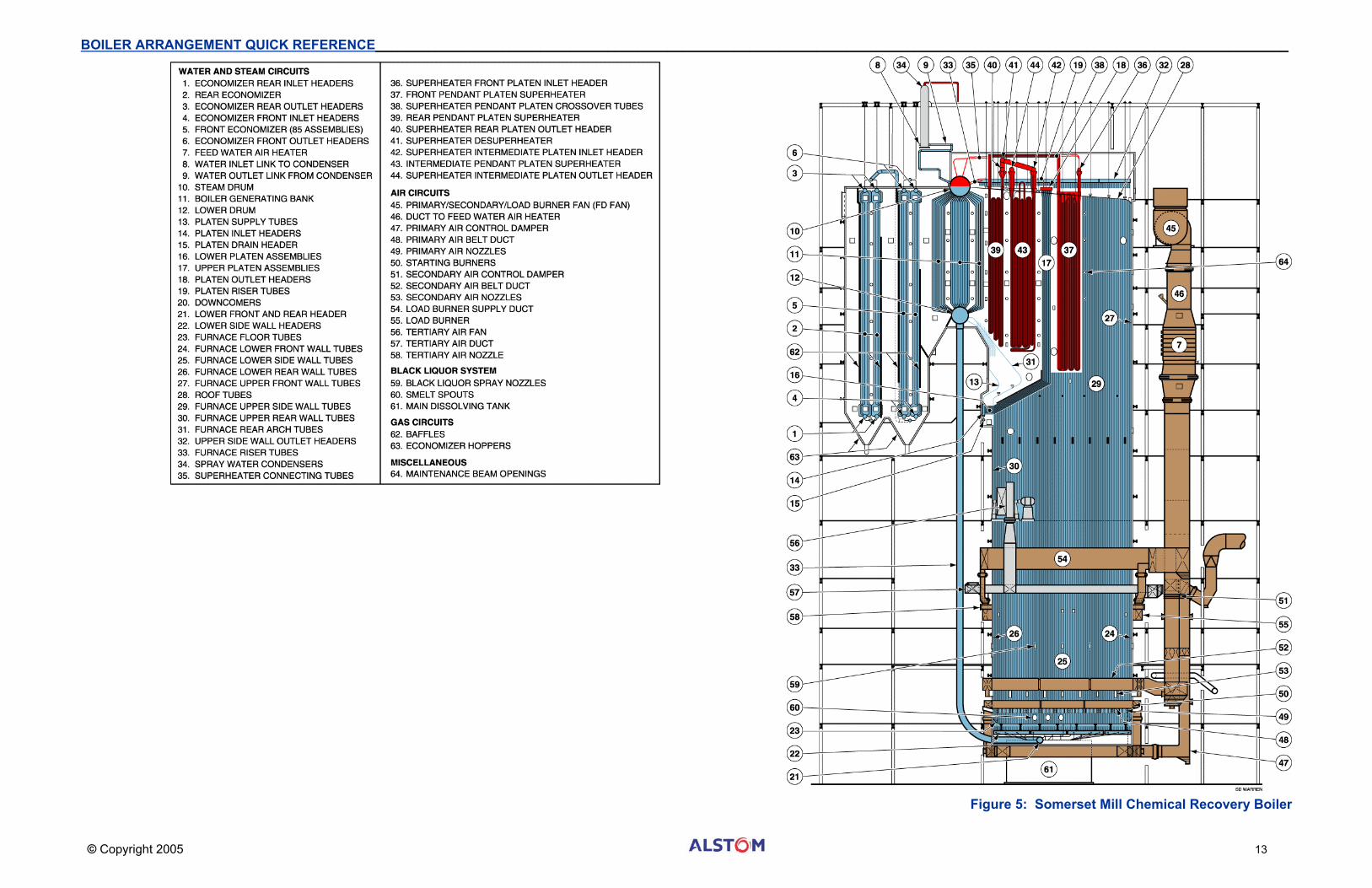
CHEMICAL RECOVERY BOILERS Somerset Mill Chemical Recovery Unit [CRU]
The following side sectional chemical recovery unit illustration is based on Sappi’s Somerset Mill CRU Contract No. 21774 located in Skowhegan, Maine. The Somerset CRU operates at 900 psig producing 497,500 lb/hr steam at 850oF. The unit was designed to convert 4,838,700 pounds of black liquor to 3,000,000 pounds of pulp digester salt cake. For supplemental heating, the load carrying oil firing equipment is capable of firing the unit to an output rate of 547,250 lb/hr. For additional information on the Pulp and Paper industry and Chemical Recovery Boiler technology refer to the Combustion Fossil Power text Fourth Edition [1991] Chapter 8, page 42.
Source of Fuel - Recovering Digester Chemicals Today’s world is that of information and communication, of which much of this information and communication takes place using paper products. Paper mills produce the paper that today’s world demands. The recovery boiler is only one of the major components within the Kraft paper mill process. Expensive and caustic chemicals are used to break down (digest) the wood pulp. Recovery of these chemicals is both economically and environmentally advantageous. Organics in the wood pulp contain carbon (black liquor) which has some heating value. Through the use of a chemical recovery boiler, the carbon can be burned, releasing heat for process steam production. The black liquor would otherwise become a waste product that would be an environmental problem and difficult to dispose. Within the last two decades, a new generation of recovery boiler was being designed with multi-level air systems and other efficiency improvements. Many of the older recovery boilers that are still operating in the paper mills today are undergoing upgrading and design changes that will increase their capacity to handle dry solids, and allow the boiler to operate within today’s environmental emission standards. For more on the subject of Boiler Emissions, refer to page 26.
Boiler General Arrangement Like most of ALSTOM’s steam generators, the boiler is top supported from a structural steel grid above the unit, with provisions for lateral and downward expansion. The furnace section comprising the front, rear and sidewalls, are suspended from the structural steel grid by hanger rods. The steam drum and downcomers are hung from two large diameter U-bolts that cradle the steam drum. The outer skin of the boiler consists of stainless steel casing covering insulation and refractory. Pourable refractory is used in the lower furnace for explosion protection as well as behind buckstays and in other difficult to access areas.
Primary, Secondary and Tertiary Air Systems Total airflow to the boiler during normal operation is the sum of three individual airflows. The air supplied to the boiler reacts with the fuel (primarily carbon from the black liquor) in the combustion process to form gaseous byproducts and ash (from impurities in the black liquor plus partially oxidized digester chemicals). The primary and secondary air levels are just above the bed. The tertiary air level is above the liquor guns. The primary and secondary air systems basically have the function; to provide combustion air and distribute air flow for effective bed coverage. The tertiary air nozzles supply the necessary air to complete the combustion process by burning off such gases as carbon monoxide, hydrocarbons and hydrogen sulfide. Unlike the primary and secondary air which is preheated, tertiary air is ambient at a fan discharge temperature of approximately 100oF. Note that some chemical recovery boilers are even being retrofitted with a fourth level of air for improved performance.
Flue Gas System The boiler operates in the balanced-draft mode, which means that under normal operation, there is a “slight” vacuum in the furnace. This negative pressure or furnace draft, is maintained by the induced draft fans. As more air and fuel are introduced to the combustion process more flue gas is created. The ID fan must increase in speed to accommodate the additional volume and maintain the draft in the furnace.
Flue Gas Flow Path Flue gas flow through the generating bank is in the downward direction. At the bottom of the generating bank, the gas makes a 180 degree turn and is directed upward between two baffles. Some of the ash entrained in the flue gas drops out at this point and is collected in the generating bank ash hopper. At the economizer inlet the flue gas makes another 180 degree turn, flowing through the front economizer in the downward direction. At the bottom of the front economizer the gas makes another 180 degree turn and is directed upward between two baffles. Again, ash entrained in the flue gas drops out at this point and is collected in the economizer ash hopper. This change of direction and ash capture method is repeated in the rear economizer. The flue gas is split into two ducts and continues to the precipitator. Ash from the various ash hoppers is collected and directed to the salt cake mixing tank where the ash is mixed with the black liquor. This ash is used to thicken the black liquor in addition to reclaiming some of the salts in the ash. This ash or cake is also collected in the precipitator ash hoppers and added to the same hopper.
Starting Burners Starting burners are positioned close to the chemical ‘bed’ to start combustion, stabilize combustion or improve bed carbon burnout. The standard for starting burners is either a natural gas or an oil-pipe igniter with an ionic flame monitoring (IFM) system. The igniter control is designed to obtain a maximum safety margin by subjecting igniter operation to a flame proving IFM circuit. Some boiler use high energy ignitors (HEI) to directly light the oil. Most of these burners are retractable for improved long-term reliability.
Load Carrying Burners There are four load carrying gas guns, one in each of the four tertiary air compartments. The load carrying burners are aimed tangent to an imaginary circle in the furnace. Each of the load carrying gas guns provides a heat input of approximately 30 million Btu/hr. The load carrying gas guns provide heat during initial startup and stabilization at low loads. Load carrying burners are used for steam production when black liquor is not available. The load carrying guns are also used to provide increased steam temperature and increased gas temperature for the purpose of increasing the black liquor concentration.
Black Liquor System The black liquor system controls the firing temperature of the heavy black liquor supplied to the furnace. The black liquor system consists of a series of conditioning equipment components arranged to give flexibility to the system with parallel backup components. Major system components include: pumps, heaters, and associated valve trains. The heavy black liquor enters the system from the concentrator transfer pump to the black liquor storage tank. Both direct and indirect heaters are used in the system to control black liquor temperature. Chemical ash from the precipitator hoppers and the economizer hoppers is mixed with the heavy black liquor in the salt cake mix tank liquor temperature and flow are measured and metered to carefully manage quality.
Boiler Water and Steam Circuits The following is a list of the major circuits from the water inlet to the superheat and reheat outlet:
• Economizer rear inlet headers • Rear economizer • Economizer rear outlet headers • Economizer front inlet headers • Front economizer (85 assemblies) • Economizer front outlet headers • Feed water air heater • Water inlet link to condenser • Water outlet link from condenser • Steam drum • Boiler generating bank • Lower drum • Platen supply tubes • Platen inlet headers • Platen drain header • Lower platen assemblies • Upper platen assemblies • Platen outlet headers • Platen riser tubes • Downcomers • Lower front and rear header • Lower side wall headers • Furnace floor tubes • Furnace lower front wall tubes • Furnace lower side wall tubes • Furnace lower rear wall tubes • Furnace upper front wall tubes • Roof tubes • Furnace upper side wall tubes • Furnace upper rear wall tubes • Furnace rear arch tubes • Upper side wall outlet headers • Furnace riser tubes • Spray water condensers • Superheater connecting tubes • Superheater front platen inlet header • Front pendant platen superheater • Superheater pendant platen crossover tubes
Boiler Water and Steam Circuit (Continued) • Rear pendant platen superheater • Superheater rear platen outlet header • Superheater desuperheater • Superheater intermediate platen inlet header • Intermediate pendant platen superheater • Superheater intermediate platen outlet header
Economizer The function of the extended economizer is to pre-heat the feedwater entering the spray water condenser. The economizer consists of two sections, the rear and front sections, and is located in the rear gas pass just after the generating bank (Boiler bank). The economizer lowers the boiler exit gas temperatures by recovering heat in the exit gas thereby increasing boiler efficiency.
Spray Water Condenser The function of the spray water condenser is to condense dry saturated steam from the steam drum for use in the desuperheater spray water system and to pre-heat the feedwater supplied to the drum. This helps to assure good feedwater quality versus using feedwater attemperating spray.
Steam Drum There are two main functions of the steam drum and internals. The first is to separate the steam from the mixture of water and steam coming from the furnace walls. The second is to distribute the incoming feedwater towards the downcomers that send water to the lower headers and generating bank tubes.
Furnace Tubes Fusion welded, water cooled tubes make up the floor, front wall, rear wall, side walls and roof of the furnace enclosure. After forming the arch, the rear wall tubes are offset to form the rear wall screen tubes. Furnace floor tubes serve as the bed surface on which the chemical recovery ‘smelting’ process takes place. Spouts around the floor allow for the extraction of this digester smelt chemical.
Generating Bank The generating bank produces saturated steam like the water walls and consists of finned tubes, spaced 6” on centers across the width of the unit. The generating bank assemblies are thirteen tubes deep. The generating bank outlet headers connect to the steam drum via risers.
Superheater Steam from the drum is directed to the superheater through multiple connecting tubes. These multi-stage pendant superheaters are located in the gas path of the convection section, just ahead of the generating bank. An in-line, contact type desuperheater injects spray water (condensed steam) directly into the flow path of the steam between the first stage superheater assemblies and high temperature superheater. The desuperheater regulates the final superheat outlet temperature.
Emergency Drain System The recovery boiler is equipped with a system that allows for rapid draining of the boiler in the event of an emergency such as a tube leaking water onto the smelt bed. This system consists of a series of motor-operated valves installed on the downcomers as well as the generating bank drain header. Emergency drains are also provided for the economizer and are installed on the lower front junction header.
VU-40 Boiler The VU-40 boiler is a field-erected, top-supported, single gas pass, thermal circulation, two-drum boiler. Its features make it particularly suitable for the range of steam and fuel conditions of both large industrial and small central-station installations. Boiler applications cover steam capacities from 100,000 to 1,000,000 lb/hr with design pressures from 200 to 1800 psig. Virtually any solid, liquid or gaseous fuel can be fired. A VU-40 boiler can be equipped with fuel burning systems for tangential, horizontal, or stoker firing of single and multiple fuels.
Completely water-cooled, the VU-40 furnace uses welded fin-tube panels or fusion-welded webs. This construction forms an air and gas tight furnace.
Diversity of fuels and fuel-firing systems typifies industrial steam generation. All grades of conventional fossil fuels, plus numerous byproduct and/or waste fuels have been fired in industrial units. The list of waste fuels is ever growing with the decreasing availability and increasing cost of fossil fuels. The list also is affected by the increasing difficulty and expense in disposing of industrial and municipal waste materials in an ecologically acceptable manner. The versatility of the top-supported drop-bottom furnace accommodates a wide variety of fuel-burning equipment and fuel choices.
VU-60 Boiler The VU-60 is a custom-designed boiler that is built from pre-engineered modular components. It is used to fire clean liquid and gaseous fuels and many waste and by-product fuels. This bottom-supported, natural-circulation steam generator ranges in capacities from 100,000 to 1,000,000 lb/hr, with design pressures to 1800 psig and superheater outlet steam temperatures to 1005oF.
The VU-60 boiler can be designed for front-wall round-burner firing or tangential firing. This unit is suitable for firing waste liquid and gaseous fuels in addition to natural gas or oil. The waterwalls consist of tube panels with welded metallic fins, producing a completely tight furnace enclosure. Insulation and lagging are applied directly over the tube panels. This construction virtually eliminates refractory maintenance because the only refractory material is the floor tile and a small amount around the water-cooled burner openings.
For steam temperatures above 825oF, the VU-60’s superheater is arranged in two stages, with interstage desuperheating for control of steam outlet temperature. Multi-loop pendant-type elements and a center connection in the large-diameter outlet header ensure even distribution of steam throughout the superheater surface. The construction requires a minimum number of header joints. Superheater elements are supported from headers located out of the gas stream above the furnace roof. These headers are supported by the furnace walls and the drum.
VU-60 boilers have also been used to recover heat from gas turbines, coke ovens, blast furnaces and smelters.
When solid wastes are burned with gaseous or liquid wastes, the VU-60 modular boiler can incorporate a stoker grate. The VU-60S (signifying a stoker-firing system) has a normal range of steam production between 75,000 and 300,000 lb/hr with operating pressures up to 1550 psig at the superheater outlet and outlet steam temperatures up to 955oF. Coal, sludge, biomass or other cellulose fuels suitable for stoker firing can be burned. Again, supplemental oil, gas or other waste fuels are fired with either a tangential firing system or front wall round burners.
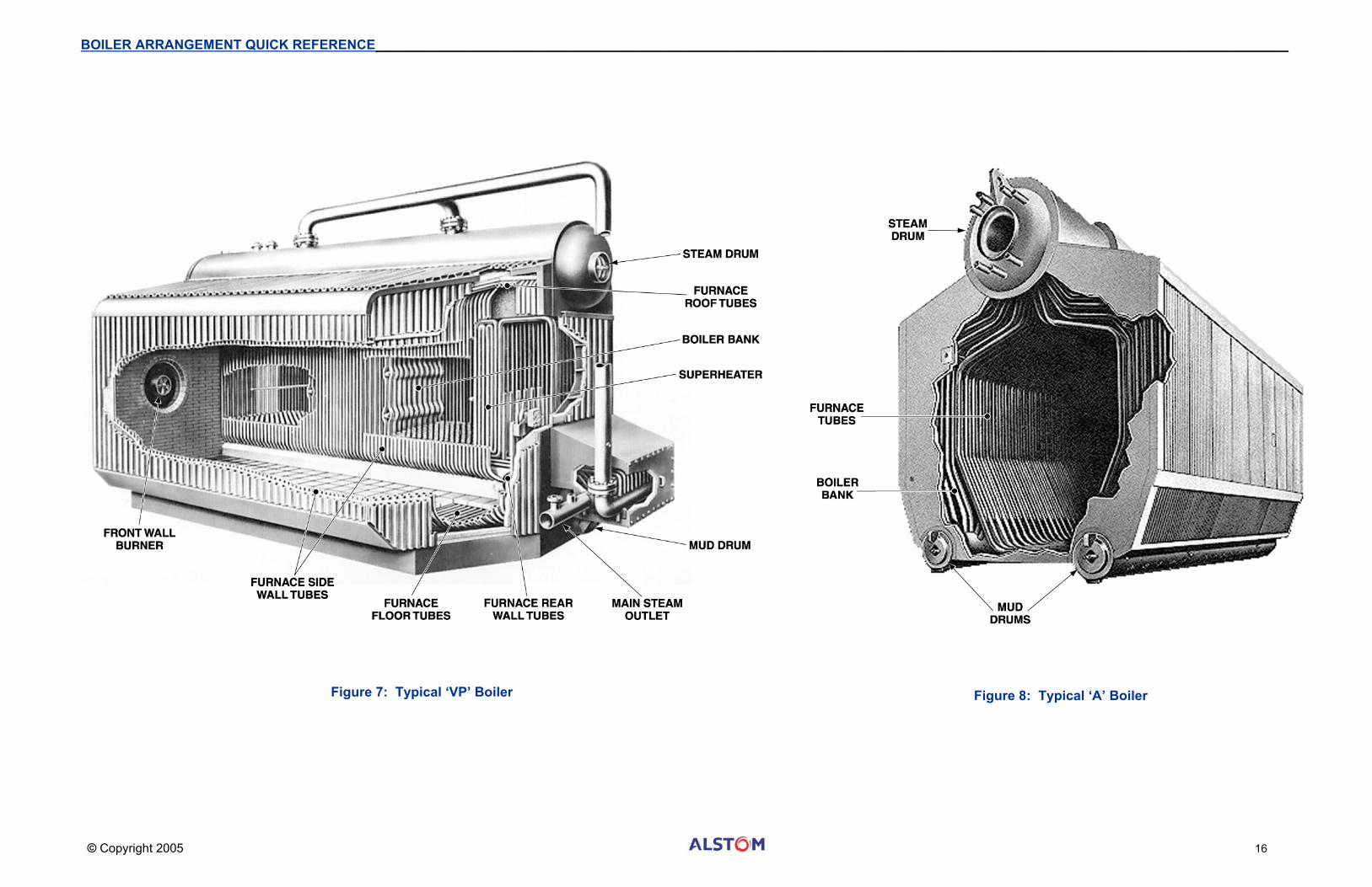
VP and A Type Shop-Assembled Boilers The growth of oil and gas suspension-fired shop-assembled boilers since their introduction in the early 1950’s has paralleled industry’s demand for higher capacities, pressures and temperatures. The evolution of these industrial boiler lines has been from 20,000 lb/hr before 1950 to approximately 600,000 lb/hr in the late 1970’s. As an example, Figure 7 shows the evolution of the VP (D type) boiler. Steam pressures and temperatures have kept pace with this capacity growth, from the saturated-steam conditions of the 1950’s to today’s operating pressures of 1650 psig and steam temperatures of 950oF.
As compared with a field-erected unit, the most significant advantage of the shop-assembled boiler is its lower cost. This differential comes from the development of standard designs with maximum use of proven fabrication procedures and minimum field-installation costs; or where only small plot areas are available.
Shop-assembled boilers can be furnished with integrated auxiliary equipment. The lower capacity units are shipped completely packaged with fuel-burning equipment, safety and combustion controls, and boiler trim. Because of shipping clearance limitations, it is not always possible or desirable to furnish the higher capacity boilers in a single package. With higher capacity units it may also be desirable to use heat-recovery equipment (economizer and/or air heater) which is shipped as a separate package.
Most shop-assembled water-tube boilers use thermal circulation and are designed for pressurized firing. Shipping clearances determine the allowable height and width dimensions of an assembled unit. Usually, the allowable shipping length is greater than can be effectively used. One of the problems of the design, therefore, is to use the available height and width to best advantage. To burn the fuel completely within the furnace, burner/furnace configuration must be properly coordinated.
The VP boiler has welded-wall construction, uses an un-heated downcomer, and a combination radiant-convection superheater which produces a flat steam-temperature characteristic. The VP boiler can be rail-shipped in two sections for capacities up to 240,000 lb/hr; larger VP units are shipped over waterways on large barges.
Another shop-assembled boiler is the ‘A’ type (Figure 8) which can generate as much as 300,000 pounds of steam per hour. The A boiler is a three-drum design with one upper (steam) drum and two lower drums. Its symmetry makes the A design ideal for rail shipment because ballast is not needed. This simplifies off-loading and handling.
Both the A and VP designs have boiler banks with a multiple simple tube circuits starting at the lower drum(s) and terminating in the steam drum. Expanded tube joints have proven to be the most practical way to connect these relatively close-spaced tubes into the drums.
Performance Requirements of Modern Industrial Boilers Industrial boilers for process-plant service are ordinarily designed to fire many different fuels, each of which influences sizing and configuration of the boiler and its auxiliaries. In addition, the primary fuel may vary over the life of the unit. Also, many manufacturing/process plants are sources of byproducts that are valuable as fuel. The need for industrial boilers to be fuel-flexible, while meeting stringent federal, state, and local emissions standards, requires special design considerations and sophisticated ancillary equipment.
Understandably, there is a preference to design industrial boilers for burning clean liquid and gaseous fuels when such are available at reasonable cost. The boilers and auxiliaries will be of minimum size and cost. Unfortunately, world demand for such prime fuels can be expected to outpace the long-term supply and will result in a decline in oil and gas burning steam generators. The eventual shift to solid fuels will require boilers that are not only initially more expensive, but also operationally more difficult. Thus, as more coal and other solid fuels are burned, there will be an increased need for pulverized-coal, stoker, and fluid-bed firing.
Owners and operators of industrial boilers must consider such developments and adapt unit performance to such things as Multifuel-Burning Capabilities: During the 70’s some industrial concerns had to convert boilers from firing coal to gas, to oil, and back to coal as the environmental requirements, fuel costs, and fuel availability changed. To protect an investment in the steam-generating facility, the owner may require multiple-fuel capability in new units. It is difficult to compare stack emissions between different industrial boiler designs. The wide variety of fuels used becomes a key consideration. Very Low NOx burners exist today for Type A and VP boilers that fire natural gas and/or refinery gasses at less than 12 /15 ppm NOx respectively. Rather than employing selective catalytic reduction (SCR) technologies, flue gas recirculation at 30% is required. For more on the subject of Power Plant Emissions, refer to page 26.
The high cost to dispose of waste make refuse, biomass, waste acids, and sludge more attractive as fuels for steam generation since they provide a viable disposal alternative. A growing number of new boiler designs will use waste fuels.
Owners and operators of industrial boilers must consider low operating costs: The cost of fuel and auxiliary power can in a short time exceed the original cost of a steam generator. Therefore, new equipment must be efficient and have a low auxiliary-power consumption.
They should also consider cogeneration potential: Simultaneous generation of electrical power and process steam is also common as users strive to extract maximum heat from their fuel. Industrial firms will more frequently select the more efficient high-pressure and high-temperature steam cycles to optimize the amount of electrical power and steam produced.
For additional information on Industrial Boilers and the Process and Power use see the Combustion Fossil Power text Fourth Edition [1991] Chapter 8.
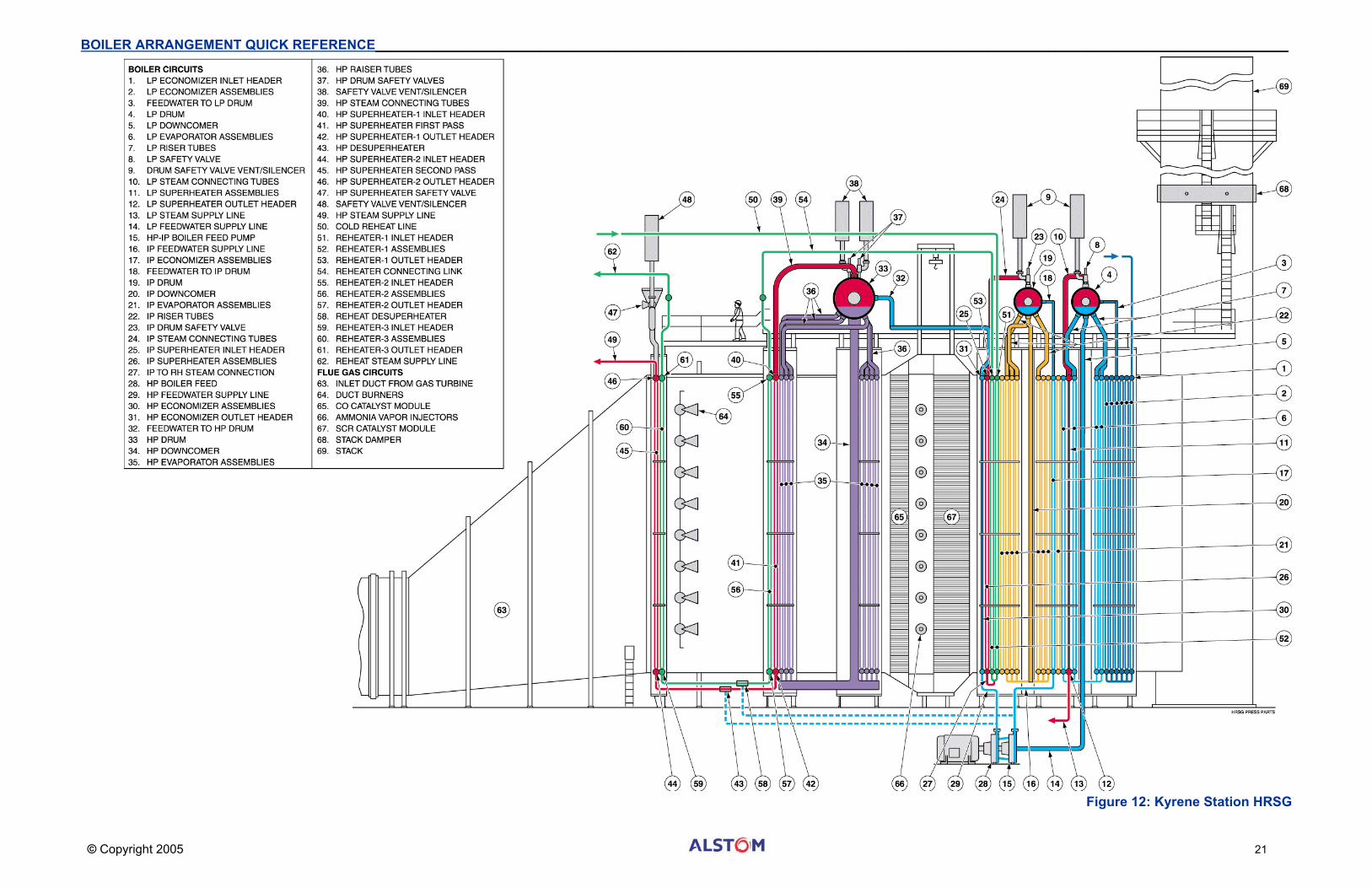
The HRSG utilizes the hot exhaust gas from the gas turbine to generate steam in three cycles; high pressure, intermediate pressure, and low pressure. Steam produced is directed to the steam turbine. The HRSG is also equipped with a reheater section to reheat steam, which has passed through the HP turbine and direct it to the IP turbine. For additional information on HRSG technology and how it relates to Gas Turbines refer to the Combustion Fossil Power text Fourth Edition [1991] Chapter 8, page 30.
Performance The sample HRSG [Kyrene] was designed to addresses multiple operating conditions. Possible ambient conditions could range from just above freezing up to 107oF. Maximum high pressure steam flow (540,700 lb/hr) occurs at 1841 psia with 1053oF. Maximum steam flow assumes full duct burner output. Partial load operation without duct burners (only heat from the gas turbine outlet) produces lower pressures (~1000 psia) with steam flows that are closer to 300,000 lb/hr.
Figure 11: Heat Recovery Steam Generator Temperature Profile
HRSG Arrangements Waste-heat boilers in gas turbine exhaust service can be configured with gas flow in the horizontal or vertical direction. Kyrene’s HRSG is a horizontal gas-flow unit. The plant covers a large area, but has excellent access for maintenance of boiler parts, duct burners, catalyst elements, and other equipment that may be associated with the HRSG. Boilers with horizontal gas flow use vertical tubes connected to headers at the top and bottom, as shown in the following figure. The tube and header assemblies may be either top-supported or bottom-supported. Although the tubes are self-supporting in the vertical direction, lateral restraints are required to control gas flow induced vibrations. Natural circulation in the steam-generating sections provides high circulation ratios without the use of pumps.
Gas Side Flow Paths Gas Turbine exhaust gas enters the HRSG at approximately 3,245,000 #/hr at 1147oF. The exhaust gas passes through the following sections:
• HP Superheater 1 • Reheater 1 • Duct Burner • HP Superheater 2 • Reheater 2 and 3 • HP Evaporator • CO Catalyst • SCR Ammonia Spray Nozzles and Catalyst • IP Superheater • HP Economizer • IP Evaporator • IP Economizer • LP Superheater • LP Evaporator • LP Economizer (FW Preheater) • Stack Damper
With the HRSG at 100% load (GT exhaust gas flow at 3,245,000 #/hr), with the duct burner firing, the exhaust gas exits the HRSG at approximately 192oF and is discharged to the stack.
HRSG Low Pressure [LP] System The heat recovery steam generator (HRSG) consists of three boiler systems operating at different pressure levels, and a reheater. The first of the three is the LP system, fed by a pre-boiler feed pump, consists of an economizer (Feedwater Preheater), a steam drum, an evaporator, and associated valves and feedwater preheater recirculation pumps. Operationally, the LP system is similar to a natural circulation boiler.
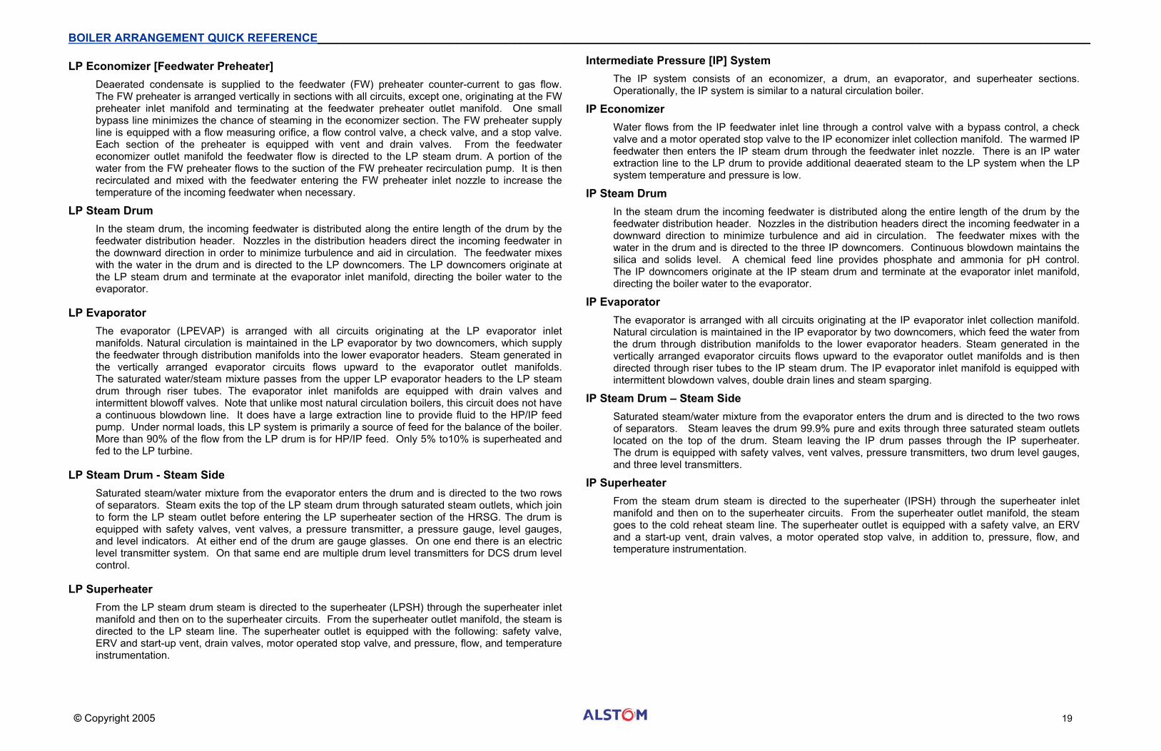
LP Economizer [Feedwater Preheater] Deaerated condensate is supplied to the feedwater (FW) preheater counter-current to gas flow. The FW preheater is arranged vertically in sections with all circuits, except one, originating at the FW preheater inlet manifold and terminating at the feedwater preheater outlet manifold. One small bypass line minimizes the chance of steaming in the economizer section. The FW preheater supply line is equipped with a flow measuring orifice, a flow control valve, a check valve, and a stop valve. Each section of the preheater is equipped with vent and drain valves. From the feedwater economizer outlet manifold the feedwater flow is directed to the LP steam drum. A portion of the water from the FW preheater flows to the suction of the FW preheater recirculation pump. It is then recirculated and mixed with the feedwater entering the FW preheater inlet nozzle to increase the temperature of the incoming feedwater when necessary.
LP Steam Drum In the steam drum, the incoming feedwater is distributed along the entire length of the drum by the feedwater distribution header. Nozzles in the distribution headers direct the incoming feedwater in the downward direction in order to minimize turbulence and aid in circulation. The feedwater mixes with the water in the drum and is directed to the LP downcomers. The LP downcomers originate at the LP steam drum and terminate at the evaporator inlet manifold, directing the boiler water to the evaporator.
LP Evaporator The evaporator (LPEVAP) is arranged with all circuits originating at the LP evaporator inlet manifolds. Natural circulation is maintained in the LP evaporator by two downcomers, which supply the feedwater through distribution manifolds into the lower evaporator headers. Steam generated in the vertically arranged evaporator circuits flows upward to the evaporator outlet manifolds. The saturated water/steam mixture passes from the upper LP evaporator headers to the LP steam drum through riser tubes. The evaporator inlet manifolds are equipped with drain valves and intermittent blowoff valves. Note that unlike most natural circulation boilers, this circuit does not have a continuous blowdown line. It does have a large extraction line to provide fluid to the HP/IP feed pump. Under normal loads, this LP system is primarily a source of feed for the balance of the boiler. More than 90% of the flow from the LP drum is for HP/IP feed. Only 5% to10% is superheated and fed to the LP turbine.
LP Steam Drum - Steam Side Saturated steam/water mixture from the evaporator enters the drum and is directed to the two rows of separators. Steam exits the top of the LP steam drum through saturated steam outlets, which join to form the LP steam outlet before entering the LP superheater section of the HRSG. The drum is equipped with safety valves, vent valves, a pressure transmitter, a pressure gauge, level gauges, and level indicators. At either end of the drum are gauge glasses. On one end there is an electric level transmitter system. On that same end are multiple drum level transmitters for DCS drum level control.
LP Superheater From the LP steam drum steam is directed to the superheater (LPSH) through the superheater inlet manifold and then on to the superheater circuits. From the superheater outlet manifold, the steam is directed to the LP steam line. The superheater outlet is equipped with the following: safety valve, ERV and start-up vent, drain valves, motor operated stop valve, and pressure, flow, and temperature instrumentation.
Intermediate Pressure [IP] System The IP system consists of an economizer, a drum, an evaporator, and superheater sections. Operationally, the IP system is similar to a natural circulation boiler.
IP Economizer Water flows from the IP feedwater inlet line through a control valve with a bypass control, a check valve and a motor operated stop valve to the IP economizer inlet collection manifold. The warmed IP feedwater then enters the IP steam drum through the feedwater inlet nozzle. There is an IP water extraction line to the LP drum to provide additional deaerated steam to the LP system when the LP system temperature and pressure is low.
IP Steam Drum In the steam drum the incoming feedwater is distributed along the entire length of the drum by the feedwater distribution header. Nozzles in the distribution headers direct the incoming feedwater in a downward direction to minimize turbulence and aid in circulation. The feedwater mixes with the water in the drum and is directed to the three IP downcomers. Continuous blowdown maintains the silica and solids level. A chemical feed line provides phosphate and ammonia for pH control. The IP downcomers originate at the IP steam drum and terminate at the evaporator inlet manifold, directing the boiler water to the evaporator.
IP Evaporator The evaporator is arranged with all circuits originating at the IP evaporator inlet collection manifold. Natural circulation is maintained in the IP evaporator by two downcomers, which feed the water from the drum through distribution manifolds to the lower evaporator headers. Steam generated in the vertically arranged evaporator circuits flows upward to the evaporator outlet manifolds and is then directed through riser tubes to the IP steam drum. The IP evaporator inlet manifold is equipped with intermittent blowdown valves, double drain lines and steam sparging.
IP Steam Drum – Steam Side Saturated steam/water mixture from the evaporator enters the drum and is directed to the two rows of separators. Steam leaves the drum 99.9% pure and exits through three saturated steam outlets located on the top of the drum. Steam leaving the IP drum passes through the IP superheater. The drum is equipped with safety valves, vent valves, pressure transmitters, two drum level gauges, and three level transmitters.
IP Superheater From the steam drum steam is directed to the superheater (IPSH) through the superheater inlet manifold and then on to the superheater circuits. From the superheater outlet manifold, the steam goes to the cold reheat steam line. The superheater outlet is equipped with a safety valve, an ERV and a start-up vent, drain valves, a motor operated stop valve, in addition to, pressure, flow, and temperature instrumentation.
High Pressure [HP] System The high-pressure system consists of an economizer, a drum, an evaporator, and three superheater sections. Operationally, the HP system is similar to a natural circulation boiler.
HP Economizer Low-pressure feedwater is supplied to the HP/IP feed pump. Feedwater at high pressure discharges the final stage of the HP/IP feed pump. The feedwater passes through an isolation valve, a flow element, a control valve with bypass control, a check valve and a motor operated valve before entering the economizer inlet manifold. From the economizer inlet manifold, the feedwater is directed to the vertically arranged economizer circuits, which terminate at the economizer outlet manifold. The flow is directed from the economizer to the HP steam drum inlet nozzle. The economizer is equipped with vent and drain valves.
HP Steam Drum In the steam drum the incoming feedwater enters through the feedwater inlet nozzle. Nozzles in the inlet header direct the flow downward in order to minimize turbulence and aid in circulation. The feedwater mixes with the water in the drum and is directed to the HP downcomers. A chemical feed line, installed in the drum, allows for injection of chemicals used to maintain boiler water chemistry. Continuous blowdown controls the silica and solids levels. Two HP downcomers originate in the HP steam drum and terminate at the evaporator inlet manifold, directing the boiler water through the evaporator distribution manifolds to the lower evaporator headers.
HP Evaporator The HP evaporator is arranged vertically in sections with all circuits originating at the HP evaporator inlet manifolds. Steam generated in the vertically arranged evaporator circuits flows upward to the evaporator outlet manifolds and is then directed through riser tubes to the HP steam drum. The evaporator inlet manifold is equipped with double drain valves and motor operated stop and control valves for intermittent blowdown.
HP Steam Drum – Steam Side Saturated steam/water mixture from the evaporator enters the drum and is directed to the two rows of separators. Steam leaves the top of the drum through three superheating connecting lines. The drum is equipped with safety valves, double vent valves, pressure transmitters, a level gauge, a pressure gauge and level transmitters.
HP Superheater From the steam drum steam is directed to the superheater (HPSH) through the superheater inlet manifold to the desuperheater link, and finally, through the finishing superheater. Steam from the HP superheater goes to the main steam outlet. From the outlet, steam is directed to the HP turbine through the HP steam line. The superheater outlet is equipped with one safety valve, an ERV and a start-up vent valve, drain valves, a motor operated stop valve, in addition to pressure, flow, and temperature instrumentation.
HP Desuperheater The superheater desuperheater controls outlet steam temperatures in the HP system and the IP system. From the HP stage of the HP/IP feed pump, heated, chemically treated, condensate quality water is sprayed into the path of the steam, reducing the steam temperature. A desuperheater spray water control valve regulates the flow of spray water supplied to the desuperheater. Desuperheater spray water control shut-off valves are located upstream and downstream of the control valve to permit isolation, when required. A drain valve, located upstream of the control valve, is used to relieve system pressure and drain the control valve piping for maintenance.
Reheater The high pressure turbine exhaust (steam) feeds the cold reheat line. One safety valve in the cold reheat line prevents over-pressurization of the exhaust system. This exhaust steam is mixed with steam from the IP superheater outlet header. The combined steam flows into the vertically arranged reheater circuits. A three-stage reheater provides the additional IP turbine heat requirements. From reheaters 1&2 the steam is routed to the RH desuperheater for steam temperature control before entering reheater 3 for further warming. From the reheater outlet header, the steam is directed to the hot reheat steam line which is equipped with double drain valves, a safety valve and a start-up vent with various instrumentation. The reheated steam is routed to the IP turbine through the RH outlet lead.
Extractions HP steam desuperheater spray water is taken from the HP feedwater pump discharge. The hot reheat desuperheater cooling water is taken from the intermediate stage of the HP/IP feed pump. Saturated IP steam can be extracted from the IP drum and fed to the LP drum under start-up conditions if necessary. This supplemental flow protects the LP superheater circuit before adequate steam production has occurred in the LP evaporator.
Auxiliary Valving Economizer sections for the low pressure system, the intermediate pressure system, and high pressure system are provided with start-up vent valves at the upper headers of each section. The vent valves are used to vent off air that has become trapped in the respective pressure sections while filling the HRSG with water. Each lower economizer header for each section is equipped with a drain valve arrangement to allow draining at shutdown. Evaporator distribution manifolds for the LP evaporator, the IP evaporator, and HP evaporator are also equipped with double drain valves to ensure complete draining of each evaporator section during shutdown of the unit. One set of double valves is an intermittent blowoff to rid the header sections of solids during operation.
Mid-West Generation - Crawford Station Unit 8 The following side sectional boiler view is based on Crawford Station Unit 8. Crawford is one of ALSTOM’s most resilient coal-fired steam generator designs. This unit was originally a C-E pressurized separated twin furnace design [PFSW] boiler built in the late 1950’s. This boiler’s furnace, and hundreds like it, were converted to a balanced draft (slight furnace internal vacuum) configuration to create a cleaner operating environment. In the late 1990’s, the coal firing system (burner-windbox) was upgraded to the low NOx burner design TFS-2000R. As a result, combustion quality was restored and an environmentally friendly emission level was achieved producing approximately 1/6th as much smog. For additional information on Steam Generator technology refer to the Combustion Fossil Power text Fourth Edition [1991] Chapter 7. For more on the subject of Power Plant Emissions, refer to page 26.
Fuel Sources The original coal furnace was designed around the combustion characteristics of the local Illinois Bituminous, 10,000 Btu/lb coal, with 5% sulfur and 15% ash. Today, Powder River Basin (PRB) coal is imported from over 1000 miles away from Montana and Wyoming. This highly reactive coal must be burned in greater quantities (~120% more per hour) to generate the same amount of heat, but it works well with the low NOx burner design. Since re-commissioning of the new burners in February 2001, the eight 703RPS coal pulverizers continue to process sufficient coal to generate 2,140,000 lb/hr main steam. This is sufficient to produce 347 megawatts of energy.
Air Supplies Total air supplied from the Forced Draft (FD) fan for the pulverized coal fired boiler consists of two air streams. Primary air (PA) transports coal dust from the pulverizers to the furnace via transport piping. Preheating the PA dries the coal dust so it won’t stick in the transport pipes. This primary air flow is boosted by exhauster fans positioned just downstream of the coal pulverizers. Secondary air (SA) flows directly to the burner windbox to control combustion. Secondary air is also preheated to stabilizes the combustion process. All of the secondary air and most of the primary air is warmed in the air heater.
Flue Gas Flow Air and flue gas are carefully controlled by a balancing act between the Forced Draft (FD) fan that produces the main flow of primary air and secondary air, and the Induced Draft (ID) fan. Operated properly, the furnace pressure is held at a slight vacuum. The resistance to the induced draft varies based on pluggage in the assembly spacing in the furnace as well as in the air heater and precipitator.
Ash Systems A secondary byproduct of burner coal is non-combustible ash. Most of the ash turns to a fine dry dust (flyash) that is stripped from the tube surfaces by sootblowers. A somewhat smaller fraction of the ash is near to a molten state that must be sheered from the wall tubes (via wall blowers, deslaggers or water cannons) and removed by a bottom ash removal system. Flyash is gathered in an electrostatic precipitator (not shown) that is able to capture 99.99% of the fine dust before it enters the environment.
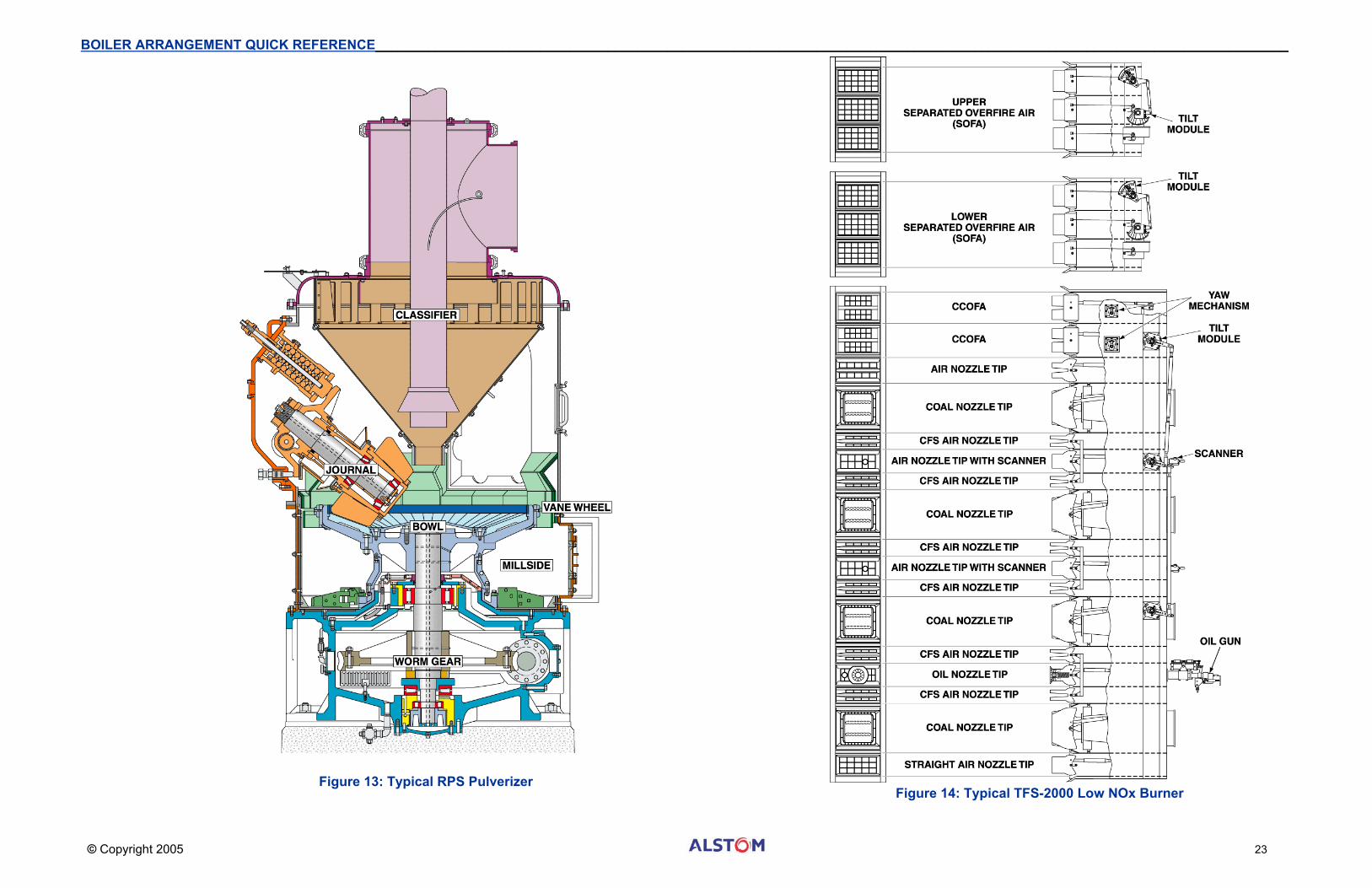
Coal Pulverization [Milling] System The original coal pulverizers are the RPS 703 design (Figure 13). The RPS pulverizer represents the first generation of CE pulverizers incorporating pressurized internals. Component design improvements and specialty material selection for the RPS pulverizer have been utilized to extend grinding element life, reduce replacement part cost, maintenance and equipment down time. The major zones and components of the RPS pulverizer include:
• Electric motor capable of 500 HP (assuming a 703 RPS size and capacity). • Single stage speed reduction gearing system (Worm Gear) that drops the motor speed from
900 RPM to a central grinding zone vertical drive shaft at approximately 50 RPM. • An air inlet plenum (Millside) that mixes incoming air from the primary air fan and the air heater,
then distributes it to the grinding zone to dry the coal before it enters the furnace. This mill bottom section also permits rejection of any hard rock that may have been blended in the coal.
• Central grinding zone where coal is passed between an upper (Journals) and lower (Bowl) grinding surfaces. These surfaces are made of extremely hard cast materials.
• Air distribution vanes and rings called Vane Wheel assemblies located at the perimeter of the grinding zone’s bowl assembly.
• Three spring-loaded grinding roller assemblies (Journals) that uniformly crush the coal. • Particle sizing system (Classifier) pneumatically sorts the very finest coal from the pulverizer
letting only the smallest particles exit to the furnace, rejecting the larger particles for regrinding under the journals.
• Suction fan (Exhauster) draws the warm dust and primary air mixture from the pulverizer at a maximum rate of 32 tons of coal per hour and discharges it into piping.
• Piping Riffle Distributors split the single fan outlet into eight burner nozzles. • Eight pulverizers and the riffle distribution system feed coal into sixty four Coal Nozzles arranged
into several layers of coal and combustion air in the tangentially (corner fired) burners. Careful manipulation of the multiple streams of coal, layered between the combustion air permits the boiler operator to not only manage furnace temperatures, but do so with lower boiler emissions.
Low NOx Burners Crawford’s new burners are the ALSTOM TFS-2000R Concentric Firing System which is the most aggressive NOx reduction design for existing tangential firing systems (Figure 14). This is a tangential coal-firing system that combines three techniques to reduce NOx. The techniques include overfire air (CCOFA and SOFA), horizontal concentric auxiliary air staging and flame attachment coal nozzle tips. Overfire air and horizontal air staging diverts and retards air and fuel mixing to cool the flame and inhibits inherent nitrogen combustion. Flame attachment tips help to stabilize the cooler fires. The burner tilt drive units at each burner corner of the furnace operate in unison so that all nozzle tips are tilted equally. During operation, the nozzle tilt position normally "modulates" between upward and downward positions based on outlet steam temperature control. If the furnace walls are slagged heavily with ash, tilts may angle down helping to sustain boiler steam drum pressure. When the boiler waterwalls are cleaned, the tilts may angle up to restore steam temperatures.
Boiler Water and Steam Circuits The following is a list of the major circuits from the feedwater inlet to the superheat and reheat outlet: • Economizer inlet header • Economizer assemblies • Economizer side wall tubes • Economizer outlet header • Economizer outlet links • Steam drum • Downcomers • Boiler circulating pump • Waterwall front drum supply tubes • Waterwall front drum • Waterwall front tubes • Waterwall front roof tubes • Waterwall front roof outlet header • Waterwall front and rear drum crossover line • Waterwall rear drum • Waterwall rear tubes • Waterwall rear arch tubes • Waterwall rear hanger tubes • Waterwall screen tubes • Waterwall rear roof tubes • Waterwall rear roof outlet header • Waterwall side wall supply tubes • Waterwall side tubes • Waterwall upper side outlet header • Waterwall extended side supply tubes • Waterwall extended side inlet headers • Waterwall extended side tubes • Waterwall extended side outlet headers • Waterwall riser tubes • Economizer recirculating line • Water cooled spacers • Superheater connecting tubes • Superheater steam cooled wall inlet header • Superheater steam cooled wall front tubes • Superheater steam cooled wall roof tubes • Superheater steam cooled wall rear tubes
Boiler Water and Steam Circuits [Continued] • Low temperature superheater horizontal inlet header • Low temperature superheater horizontal assemblies • Low temperature superheater pendant assemblies • Low temperature superheater outlet headers • Low temperature superheater connecting links • Superheater desuperheater • Superheater connecting links • High temperature superheater channel inlet header • High temperature superheater front platen assemblies • High temperature superheater rear platen assemblies • High temperature superheater channel outlet headers • High temperature superheater front pendant assemblies • High temperature superheater rear pendant assemblies • High temperature superheater pendant outlet header • Cold reheat inlet connections • Reheat channel inlet header • Reheat platen assemblies • Reheat channel outlet headers • Rear pendant inlet header • Reheat rear pendant assemblies • Reheat front pendant assemblies • Reheat pendant outlet header
Coal Combustion Emissions The combustion product from the furnace is typically four gases (See page 26 for more on this). The overwhelming volume of gas is carbon dioxide (CO2) but trace amounts of emission contamination comes from the burning of atmospheric and chemical nitrogen (NOx) and chemical sulfur (SOx). Carbon dioxide is not considered a toxic gas in the classic sense, but any incomplete combustion can produce carbon monoxide (CO) which is toxic. Accordingly, care is taken to provide uniform mixing of fuel and air at multiple levels and even an excess of combustion air to reduce CO to an absolute minimum. NOx is reduced below regulated levels by the TFS-2000R burner design mentioned above. SOx emissions are similarly managed below regulated levels by buying coals naturally low in sulfur. See the following section for more on this topic. This is one of the primary reasons that Powder River Basin (PRB) coals are so widely used in the west and mid-western United States. Eastern states, which are further from the low sulfur coal fields of Wyoming and Montana, may need to install environmental control systems that react with the sulfur in the flue gas keeping it out of the atmosphere.
The above steam generator reflects late 1950’s technology as well as several design retrofits. For additional information on the latest technology refer to the Combustion Fossil Power text Fourth Edition [1991] Chapter 7, page 7-16 for ‘Controlled’ Circulation and page 7-24 for ‘Supercritical’ Steam Generators.
The installation of highly efficient precipitators, baghouses, and flue-gas desulfurization systems (FGDS) has become increasingly necessary. Power-plant owners must include them in their planning to obtain permission to start construction of a new facility. Additionally, boiler furnace modifications and system controls must be applied to reduce other gaseous emissions such as oxides of nitrogen. These changes add considerably to the complexity and cost of equipment operation and maintenance. Two other major industry changes that impact emission are changes in fuel availability and regulation for air quality. Discounting inflation, the cost of installation of a major facility has more than doubled since the imposition of environmental laws. Because of permits needed to satisfy ecological statutes, and the time taken to debate these in public, the time required to construct a fossil plant has increased 2 to 3 years.
Three classes of emissions are currently judged significant from an air-quality standpoint: particulate matter, sulfur oxides, and nitrogen oxides. Historically, particulate matter has received the greatest attention because it is easily seen and often labeled a public nuisance. The concern about sulfur oxide comes from its possible health effects and from its potential to damage vegetation. Oxides of nitrogen are also significant because they participate in complex chemical reactions that lead to formation of photochemical smog in the atmosphere. As the regulations have tightened, ALSTOM Power’s boilers and flue gas cleaning systems have been very successful at keeping pace. The following four examples demonstrate how well:
• Large pulverized coal fired boilers (tangentially fired) designed in the 1970’s had nitrogen oxide emissions of between 0.4 to 0.9 pounds of NOx for every 1,000,000 Btu of heat (#NOx/mmBtu). Note that one million Btu is approximately 100 pounds of coal. Today the modified coal firing systems are down to 0.15 - 0.25 #NOx/mmBtu. When a Selective Catalytic Reduction (SCR) system is added, the NOx can be as low as 0.05 #NOx/mmBtu. That correlates to NOx emissions that are 1/18th of what might have been common only three decades ago. Sulfur emission, in that same period, have been dropped from 0.3 - 1.2 #/mmBtu to as low as 0.06 #/mmBtu. That can be seen as a twenty-fold improvement. Particulates from precipitators and fabric filter baghouses have improved as well with present day emissions of 0.01 - 0.03 #/mmBtu.
• Large Circulating Fluidized Bed (CFB) boilers today are using Selective Non-Catalytic Reduction (SNCR) and SO2 Flash Dry Absorbers (FDA). They have the ability to produce NOx emission levels below 0.03 and with 95% sulfur reduction levels, which correlates to SOx emission that are 0.02 - 0.6 #/mmBtu.
• Smaller industrial FiCirc Fluid Bed (FB) boilers burning biomass are capable of running very low CO and greater than 99% Sulfur removal achieving 10 - 15 ppm SO2 and similar NOx emissions. This corresponds to less than 0.02 #/mmBtu when a NOx control SNCR is employed. A FiCirc design utilizing a baghouse, limestone injection and SCR being commissioned in 2005 burning coal will achieve less than 0.075 #NOx/mmBtu and 0.12 #SOx/mmBtu.
• The most extreme low emissions levels, however, are achieved by natural gas fired Gas Turbines (GT) feeding Heat Recovery Steam Generators (HRSG). Utilizing both CO and NOx SCR catalysts, these plants have virtually no CO or SOx emissions, and have NOx emissions of 0.002 - 0.003 #/mmBtu. Compared on a megawatt basis, the GT-HRSG plants have 1/150 th the nitrogen oxide emissions of coal fired boilers of today. They produce 1/1000th the emission level of a coal-fired boiler of the early 1970’s.
Sulfur Oxide Emissions As fuels burn, most of the sulfur content is converted to the sulfur oxides SO2 and SO3. Sulfur varies widely for different coals and may range from less than 0.2% to over 5%. In general, 90 percent or more of the sulfur in the fuel will oxidize to gaseous sulfur di-oxide (SO2). Further conversion of SO2 to SO3 takes place. The formation of SO3 in a boiler creates a corrosive atmosphere that damages the boiler and backend equipment, particularly when liquid sulfuric acid accumulates on plate surfaces or around tubing.
Nitrogen Oxide Emissions During the combustion process in a conventional furnace, oxides of nitrogen (collectively referred to as NOx) form in the high-temperature region in and around the flame zone. The oxidation of both atmospheric nitrogen and nitrogen contained in the fuel is the cause. Either the available nitrogen in the coal or the flame’s peak temperature and the oxygen present influence the rate of formation. NOx output is lowered by altering furnace combustion conditions. The plant can reduce NOx by what is termed ‘in-furnace’ solutions or by employing ‘post-furnace’ gas cleaning solutions. For ALSTOM, our primary family of ‘in furnace’ solution is the Low NOx Concentric Firing (LNCFS) burner. The two most common ‘post-furnace’ solutions are Selective Catalytic Reduction (SCR) and Selective Non-Catalytic Reduction (SNCR) systems. Both employ an ammonia reaction that results in the reduction of NOx to inert molecular nitrogen and water vapor.
Particulate Emissions Emissions from coal-fired boilers vary considerably depending on the ash content of the coal and the type of firing. A pulverized-coal-fired unit can be expected to have 60 to 80 percent of the coal ash normally leaving the furnace with the flue gas. The balance of the ash leaves through the boiler bottom-ash removal system, and hoppers under economizers or air heaters. Flyash is the combination of inert or inorganic residue in pulverized-coal particles with varying amounts of carbon or coke particles resulting from incomplete combustion. In general, the inorganic ash particles consist primarily of silicates, oxides and sulfates together with small quantities of phosphates and other trace compounds. Particle size varies from below 0.01 micron diameter to over 100 microns. For additional information on particulate emissions and related technology refer to ‘Combustion Fossil Power’ text Fourth Edition [1991] Chapter 15, page 15-4.
Influence of Coal And Combustion Characteristics on Particulate Matter Emissions Changing coal characteristics has a major effect on the removal efficiency of flyash. The variation in ash content, ash composition, ash resistivity and particle size distribution requires an engineering evaluation of collection principles to reduce emissions to required levels.
Influence of Volumetric Gas Flow on Particulate Matter Emissions No matter what type of flyash collector is to be installed on a boiler, it is essential that it be designed for the correct gas volume. Manufacturers design and size their equipment based upon their testing and field experience with that coal.
Filter Particle Capture In a filter baghouse process forces are exerted directly on the particulates rather than the gas as is done in electrostatic dust capture. As the filter surfaces gather flyash, fan power consumption and draft losses increase until the particles can be shed. For an example of a baghouse, refer to Figure 3, page 6.
ELECTROSTATIC PARTICLE CAPTURE In electrostatic precipitation, suspended particles in the gas are electrically charged, then driven to collecting electrodes by an electrical field. The dust covered electrodes are rapped to cause the particles to drop into collecting hoppers. Compared to a fabric filter process, effective separation of particles can be achieved with lower power expenditure, with negligible draft loss, and with little or no effect on the composition of the gas. To meet a demand for ultra-high efficiency collectors of rugged construction and high reliability, manufacturers used the patents held by Frederick Gardner Cottrell to develop the rigid-frame precipitator. The early generation basic design incorporated segmented collecting plates and rigid discharge electrodes, with rapping on the discharge frame. Later designs replaced the discharge plates with wire type discharge electrodes.
Electrostatic Precipitator Design Factors The seven most significant precipitator designs points to consider are: • Specific collection area • Treatment time • Gas velocity • Electrode configuration and spacing • Number of fields • Automatic voltage control • Hopper size and slope
LEGEND 1. ROOF SECTION • Transformer rectifier sets • Support insulators 2. INLET PLENUMS 3. GAS DISTRIBUTION SYSTEMS 4. HOPPER - COAL BURNING SYSTEMS • Hopper heaters • Ash systems • Hopper level detectors • Access doors 5. DISCHARGE ELECTRODE SYSTEM • Discharge electrodes Wires & Frame • Rapper drive insulators • Rapper drives • Bearings • Hammers 6. COLLECTING SYSTEM • Collecting plate rapper drives • Collecting plates • Bearings • Hammers • Shock bars & Anvil
RECOVERY BOILER PRECIPITATOR SYSTEMS (NOT SHOWN) • Drag conveyors • Rotary air locks • Disc-type Isolation dampers
WET FLUE GAS DESULFURIZATION As noted on page 26 sulfur dioxide (SO2) is a gaseous byproduct formed when coal is burned in the boilers. As combustion occurs, the sulfur in the fuel reacts with oxygen, resulting in the formation of various sulfur-containing compounds, primarily SO2. The higher the concentration of sulfur in the coal, the greater the concentration of SO2 in the flue gas exiting the boiler. Due to environmental restrictions placed upon SO2 emissions, it is necessary to remove and dispose of most of this compound before it enters the atmosphere through the stack. The exact chemical reactions which occur in a wet limestone (CaCO3) scrubbing system may be characterized as a series of steps. Although these steps are presented sequentially, they can occur simultaneously. The principal steps are: absorption, neutralization, regeneration, oxidation, and precipitation. The reactions involved in the process produce calcium sulfite, calcium sulfate and carbon dioxide.
CaCO3 + SO2 = CaSO3 + CO2 Followed by CaSO3 + Oxygen = CaSO4 (Gypsum)
The main piece of equipment in the Flue Gas Desulfurization (FGD) System is the Spray Tower Absorber, where the absorption of SO2 occurs. The entire FGD System can be broken down into the following systems:
• Flue Gas Handling • Absorption and Oxidation • Mist Eliminators • Limestone Handling • Reagent Preparation • Backup Reagent Preparation • Reagent Feed System • Primary Dewatering • Secondary Dewatering • Auxiliary Storage • Filtrate Handling • Raw Water and Equipment Cooling • Instrument Air
The following information covers a few of the major systems. For additional information on sulfur emissions and related technology refer to ‘Combustion Fossil Power’ text Fourth Edition [1991] Chapter 15, page 15-26.
Flue Gas Handling System Induced draft fans route flue gas to the stack via ducts and dampers, or into an Absorber inlet manifold, from which the flue gas will be directed into an Absorber. The Flue Gas Handling System consists of bypass ducts equipped with double-louver dampers and guillotine isolation gates. The Absorber outlet ducts have neither dampers nor isolation gates.
The Absorber consists of two major sections: the Absorber tower and the Reaction Tank. The Absorber is the area where the SO2 is removed from the flue gas. Each of the boilers may need two Absorbers, each designed to handle 50% of the total flue gas.
Absorber As the flue gas enters the Absorber, it is sprayed with a slurry solution. The recycle slurry system, which includes four or more pumps per Absorber, draws slurry from the Reaction Tank and delivers it to four or more spray elevations (one pump dedicated to each level). Each spray header elevation is equipped with spray nozzles that distribute the slurry across the spray tower. The slurry contacts the flue gas and absorbs the sulfur dioxide. Contact between the gas and slurry begins the reaction process, which continues as the mixture falls into the Reaction Tank.
Before entering the stack, the cleaned flue gas travels upward to the Mist Eliminators (MEs), where both entrained moisture and excess slurry are removed. When the droplets carried by the gas impinge on the ME vanes, they combine with other droplets and roll off. The MEs are equipped with a wash system to prevent pluggage of the vanes. Both the runoff slurry and the wash water fall into the Reaction Tank.
Reaction Tank Slurry droplets fall from the Absorber tower to the Reaction Tank, where the SO2 is converted into both calcium sulfite and calcium sulfate. The Reaction Tank is equipped with four side-mounted agitators to keep the solids suspended and to distribute the oxidation air, which is injected into the tank just in front of each agitator.
Oxidation Air System The FGD System is designed to produce, as a byproduct, a salable grade gypsum. The oxidation air converts 99% of the calcium sulfite to calcium sulfate, or gypsum. The oxidation air system consists of several Oxidation Air Blowers, each with an independent lubrication system. During normal operation, one blower per unit is operating, with one common standby blower. The blowers compress air and deliver it to the Absorber air lances located in front of each Reaction Tank agitator. The agitators ensure good distribution of the air into the Reaction Tank slurry. Before entering the Reaction Tank, the air is cooled by saturation water to prevent system pluggage and to protect the fiberglass piping from excessive temperatures.
Reagent Preparation System The supply of limestone slurry to the Reagent Feed System is controlled by the Primary or Backup Reagent Preparation Systems. Normally the Primary Reagent Preparation System will be in use. This system grinds limestone rock until the mesh size meets the design requirement. The grinding occurs in a singe ball mill where limestone rock and water are added on a continuous as needed basis. The outlet of the Limestone Ball Mill is fed to a Mill Product Tank where the slurry is pumped to a set of hydrocyclones for classification. The overflow product is routed to the Reagent Feed Tank(s) for use in the Reaction Tank, and the underflow is routed back to the ball mill for further grinding.
Reagent Feed System The Reagent Feed System provides limestone slurry to the Absorbers to maintain proper pH levels in the Reaction Tanks. The feed system consists of two feed tanks, each with a top-mounted agitators, and two feed pumps (one per tank). Limestone slurry is fed from either the Reagent Preparation System or the Backup Reagent Preparation System to the Reagent Feed Tanks. Each Reagent Feed Pump circulates slurry through a loop back to the Reagent Feed Tank. The common loop has a line to each Absorber, equipped with control valves that modulate to feed slurry to the Reaction Tanks. The feed valves modulate in response to slurry pH signals.
Primary Dewatering System The function of the Primary Dewatering System is to reduce the solids concentration in the slurry that was removed from the Reaction Tank by the Classifier Feed Pumps. The reduced-density slurry (i.e., Hydrocyclone Classifier overflow) is then returned to the Reaction Tank and the FGD Bleed Tank. The Classifier Feed Pumps continuously draw slurry from the Reaction Tank and either transfer it to the Hydrocyclone Classifiers, or recirculate it back to the Reaction Tank. Dilute slurry (overflow) produced by the hydrocyclones flows by gravity to either the Reaction Tanks or the FGD Bleed Tank. The thickened underflow flows by gravity to the Secondary Dewatering System.
Secondary Dewatering System The Secondary Dewatering System consists of a Distribution Box, two horizontal belt filter systems, and auxiliary equipment. Normally, one belt filter system will be in operation while the other is in standby. Each belt filter system can accommodate the feed from both absorbers.