28
Bosch BVA 2.0 Series Air Handler 2-3-4-5 Ton Capacity R410A Installation Instructions

Bosch BVA 2.0 Series Air Handler2-3-4-5 Ton CapacityR410A
Installation Instructions

2 | Bosch IDS BVA 2.0 Installation Instructions
02.2019 | Bosch Thermotechnology Corp.Data subject to change
Installation Instructions Bosch IDS BVA 2.0 | 3
Bosch Thermotechnology Corp. | 02.2019 Data subject to change
Table of Contents
1 Key to Symbols and Safety Instructions 4
1.1 Key to Symbols 4
1.2 Safety 4
2 General 6
2.1 Installations in High Humidity Environments 6
2.2 Unit Dimensions 9
3 Applications 10
3.1 Vertical Upfl ow 10
3.2 Vertical Downfl ow 10
3.3 Horizontal 10
3.4 Installation in an Unconditioned Space 12
4 Electrical wiring 13
4.1 Power Wiring 13
4.2 Control Wiring 13
4.3 Grounding 13
4.4 Electrical Data 13
4.5 Electric Heat Kit MCA/MOP Data 14
5 Airfl ow Performance 15
5.1 Indoor Fan Motor Function 16
6 Ductwork 17
7 Refrigerant Connections 18
7.1 Condensate Drain Connection 18
8 Air Filter (Not Factory-Installed) 19
9 Filter Installation Dimensions 20
10 Maintenance 21
10.1 Cleaning Precautions 21
10.2 Regular Maintenance 21
11 Wiring Diagrams 22

4 | Bosch IDS BVA 2.0 Installation Instructions
02.2019 | Bosch Thermotechnology Corp.Data subject to change
1 Key to Symbols and Safety Instructions
1.1 Key to Symbols
Warnings
Warnings in this document are identifi ed by a warning triangle printed against a grey background.Keywords at the start of a warning indicate the type and seriousness of the ensuing risk if measures to prevent the risk are not taken.
The following keywords are defi ned and can be used in this document:
DANGER indicates a hazardous situation which, if not avoided, will result in death or serious injury.
WARNING indicates a hazardous situation which, if not avoided, could result in death or serious injury.
CAUTION indicates a hazardous situation which, if not avoided, could result in minor to moderate injury.
NOTICE is used to address practices not related to personal injury.
Important information
This symbol indicates important information where there is no risk to people or property.
1.2 Safety
Please read before proceeding
WARNING:
These instructions are intended as an aid to qualified, licensed service personnel for proper installation, adjustment and operation of this unit. Read these instructions thoroughly before attempting installation or operation. Failure to follow these instruction may lead to improper installation, adjustment, service or maintenance possibly resulting in fire, electrical shock, property damage, personal injury or death.
This document is customer property and is to remain with this unit. These instructions do not cover all the diff erent variations of systems nor does it provide for every possible contingency to be met in connection with installation.
WARNING: FIRE, ELECTRICAL SHOCK, PROPERTY DAMAGE, PERSONAL INJURY, OR DEATH
All phases of this installation must comply with NATIONAL, STATE AND LOCAL CODES. If additional information is required please contact your local distributor.
WARNING: ELECTRICAL SHOCK
Disconnect all power to unit before installing or servicing. More than one disconnect switch may be required to deenergize the equipment. Hazardous voltage can cause severe personal injury or death.
WARNING: ELECTRICAL SHOCK
If removal of the blower assembly is required, all disconnect switches supplying power to the equipment must be deenergized and locked (if not in sight of unit) so the field power wires can be safely removed from the blower assembly. Failure to do so can cause electrical shock resulting in personal injury or death.
WARNING: FIRE, ELECTRICAL SHOCK, PROPERTY DAMAGE, PERSONAL INJURY, OR DEATH
Because of possible damage to equipment or personal injury, installation, service, and maintenance should be performed by trained, qualified service personnel. Consumer service is recommended only for filter cleaning / replacement. Never operate the unit with the access panels removed.

Installation Instructions Bosch IDS BVA 2.0 | 5
Bosch Thermotechnology Corp. | 02.2019 Data subject to change
WARNING:
This product can expose you to chemicals including Lead and Lead components, which are known to the State of California to cause cancer and birth defects or other reproductive harm. For more information go to www.P65Warnings.ca.gov.
WARNING: ELECTRICAL SHOCK
The unit must be permanently grounded. Failure to do so can result in electrical shock causing personal injury or death.
CAUTION: FIRE HAZARD
The material of plenum and ductwork must meet the latest edition of the NFPA 90B standard.
NOTICE:
Make sure the blower motor support is tight (3-motor mounting bolts - Fig. 1). Then check if wheel is tightly secured to motor shaft before operating unit.
Figure 1
Blower Motor Mounting Bolt
6 | Bosch IDS BVA 2.0 Installation Instructions
02.2019 | Bosch Thermotechnology Corp.Data subject to change
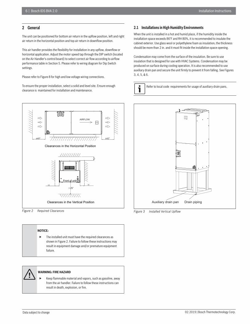
2 General
The unit can be positioned for bottom air return in the upfl ow position, left and right air return in the horizontal position and top air return in downfl ow position.
This air handler provides the fl exibility for installation in any upfl ow, downfl ow or horizontal application. Adjust the motor speed tap through the DIP switch (located on the Air Handler's control board) to select correct air fl ow according to airfl ow performance table in Section 5. Please refer to wiring diagram for Dip Switch settings.
Please refer to Figure 8 for high and low voltage wiring connections.
To ensure the proper installation, select a solid and level site. Ensure enough clearance is maintained for installation and maintenance.
Figure 2 Required Clearances
25’’
Front of unit
Clearances in the Horizontal Position
Clearances in the Vertical Position
≥ "04 ≥40"
AIRFLOW
NOTICE:
The installed unit must have the required clearances as shown in Figure 2. Failure to follow these instructions may result in equipment damage and/or premature equipment failure.
WARNING: FIRE HAZARD
Keep flammable material and vapors, such as gasoline, away from the air handler. Failure to follow these instructions can result in death, explosion, or fire.
2.1 Installations in High Humidity Environments
When the unit is installed in a hot and humid place, if the humidity inside the installation space exceeds 86℉ and RH 80%, it is recommended to insulate the cabinet exterior. Use glass wool or polyethylene foam as insulation; the thickness should be more than 2 in. and it must fi t inside the installation space opening.
Condensation may come from the surface of the insulation. Be sure to use insulation that is designed for use with HVAC Systems. Condensation may be produced on surface during cooling operation. It is also recommended to use auxiliary drain pan and secure the unit fi rmly to prevent it from falling. See Figures 3, 4, 5, & 6.
Refer to local code requirements for usage of auxiliary drain pans.
Figure 3
Auxiliary drain pan Drain piping
Installed Vertical Upfl ow

Installation Instructions Bosch IDS BVA 2.0 | 7
Bosch Thermotechnology Corp. | 02.2019 Data subject to change
Figure 4 Installed Horizontal Right
Auxiliary drain panDrain piping
Figure 5
Auxiliary drain pan
Drain piping
Installed Horizontal Left
Figure 6
Inner extra drain pan
Auxiliary drain panDrain piping
Installed Vertical Downfl ow
NOTICE:
Inner extra drain pan is recommended to be installed for 4 and 5 ton vertical downflow applications installed in high humidity environments. This inner extra drain pan can be ordered from the manufacturer as a spare part. Refer to Figure 6.
NOTICE:
For high humidity installations which include electric heat strips, it is recommended to install spacing brackets (available as a spare part from the manufacturer) between the heater and the heater collar to prevent condensation from forming on the collar.
8 | Bosch IDS BVA 2.0 Installation Instructions
02.2019 | Bosch Thermotechnology Corp.Data subject to change
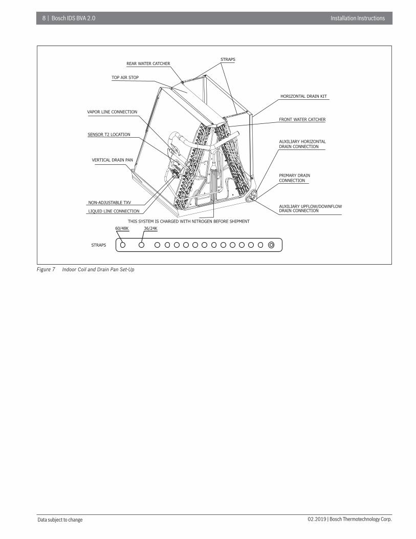
Figure 7
HORIZONTAL DRAIN KIT
VAPOR LINE CONNECTION
LIQUID LINE CONNECTION
PRIMARY DRAIN CONNECTION
VERTICAL DRAIN PAN
AUXILIARY HORIZONTAL
AUXILIARY UPFLOW/DOWNFLOW
STRAPSREAR WATER CATCHER
TOP AIR STOP
DRAIN CONNECTION
DRAIN CONNECTION
FRONT WATER CATCHER
60/48K 36/24K
STRAPS
THIS SYSTEM IS CHARGED WITH NITROGEN BEFORE SHIPMENT
NON-ADJUSTABLE TXV
SENSOR T2 LOCATION
Indoor Coil and Drain Pan Set-Up

Installation Instructions Bosch IDS BVA 2.0 | 9
Bosch Thermotechnology Corp. | 02.2019 Data subject to change
2.2 Unit Dimensions
Figure 8
UPFLOW UNIT SHOWN:THE UNIT CAN BE POSITIONED FOR BOTTOM AIR RETURN IN THE UPFLOW POSITION, LEFT AND RIGHT AIR RETURN IN THE HORIZONTAL POSITION, OR TOP AIR RETURN IN DOWNFLOW POSITION.
WA105 16
25” CLEARANCE IS REQUIRED IN THE FRONT OF THE UNIT FOR FILTER AND COIL MAINTENANCE.
SUPPLY AIR
FLANGES ARE PROVIDED FOR FIELD INSTALLATION
ELECTRICAL CONNECTIONS THROUGH TOP OR EITHER SIDE
LOW VOLTAGE CONNECTION
CIRCUIT BREAKER SWITCH (FOR ELECTRIC HEATER ONLY)
VAPOR LINE CONNECTION COPPER TUBE (SWEAT)
LIQUID LINE CONNECTION COPPER TUBE (SWEAT)
AUXILIARY DRAIN CONNECTION 3/4" FEMALE PIPE THREAD (NPT)
AUXILIARY DRAIN CONNECTION 3/4" FEMALE PIPE THREAD (NPT)
PRIMARY DRAIN CONNECTION 3/4" FEMALE PIPE THREAD (NPT)
H
D
HIGH VOLTAGE CONNECTION 1- DIA. KNOCK OUTS
4", 3/8", 3/1- 8"7/
Model SizeDimensions Inch [mm]
Unit Height "H" Unit Width "W" Unit Length "D" Supply Duct "A" Liquid Line / Vapor Line
24 46-1/2 [1180] 19-5/8 [500] 21-5/8 [550] 18 [456] 3/8 / 3/4 [9.5]/[19]
36 46-1/2 [1180] 19-5/8 [500] 21-5/8 [550] 18 [456] 3/8 / 3/4 [9.5]/[19]
48 54-1/2 [1385] 22 [560] 24 [610] 19-1/2 [496] 3/8 / 7/8 [9.5]/[22]
60 54-1/2 [1385] 22 [560] 24 [610] 19-1/2 [496] 3/8 / 7/8 [9.5]/[22]
Table 1

1 0 | Bosch IDS BVA 2.0 Installation Instructions
02.2019 | Bosch Thermotechnology Corp.Data subject to change
3 Applications
3.1 Vertical Upfl ow
Vertical Upflow configuration is the factory default on all models (see Figure 8).
If return air is to be ducted, install duct flush with floor. Use fireproof resilient gasket 1/8 to 1/4 in. thick between the ducts, unit and floor. Set unit on floor over opening.
Torque applied to drain connections should not exceed 15 ft.lbs. For vertical upfl ow and horizontal right installations, dimensions for refrigerant and drain pipes may be found in Figure 9.
Figure 9
1-1/4
2-11/12
1-3/8
2-1/4
1-1/42-13/16
1-4/7
H1
2-3/4
AIRFLO
W
Dimensions For Air Handler (Coil Section)
Model Size "H1" Inch [mm]
24/36 13-1/5 [335.5]
48/60 13-7/8 [352.8]
Table 2
3.2 Vertical Downfl ow
Conversion to Vertical Downfl ow:
A vertical upfl ow unit may be converted to vertical downfl ow. Remove the coil access panel and indoor coil and reinstall 180° from original position. See Figure 10 and Figure 11.
Figure 10
1-1/4
2-11/12
1-3/8
1-1/4
1-9/16
H2 2-3/4
H1
AIR
FLO
W
Dimensions For Air Handler (Coil Section)
Model Size "H1" Inch [mm] "H2" Inch [mm]
24/36 17-2/5 [441.5] 6-2/5 [162.5]
48/60 22-1/6 [563.5] 10-1/2 [267.2]
Table 3
3.3 Horizontal
Horizontal right is the default factory confi guration for all models.
Conversion to Horizontal Left:
A vertical upfl ow unit may be converted to horizontal left by removing indoor coil assembly and reinstalling coil as shown for left hand air supply. See Figure 11.
Rotate the unit 90° into the horizontal left position, with the coil compartment on the right and the blower compartment on the left.
Reinstall the indoor coil 180° from original position. Ensure the retaining channel is fully engaged with the coil rail. See Figures 11 and 12.
An additional field supplied drain pan kit is recommended when the unit is configured for the horizontal position over a finished ceiling and/or living space.

Installation Instructions Bosch IDS BVA 2.0 | 11
Bosch Thermotechnology Corp. | 02.2019 Data subject to change
Steps for Changing Cabinet Orientation to Vertical Downfl ow OR Horizontal Left Orientation
1. Remove the screws and front panel and disconnect the T2 sensor wire's molex plug from the board (Figure 10, Step 1).
2. Pull out the coil with the sensor wire attached (do not disconnect the T2 sensor from the liquid pipe on the A coil). Pull the sensor wire through the liquid line hole in the cabinet cover (see 2A on Figure 10, Step 2).
Figure 11
STEP 2
STEP 1
STEP 3
2A
3A
Vertical Downfl ow & Horizontal Left Applications Conversion
3. Replace the coil in the correct orientation and secure in place. Remove the knockout (labeled 3A in Figure 10, Step 3) in the side of the cabinet, and add the rubber grommet from the included accessory bag. Connect the molex plug end of the sensor wire to the control board (insert wire through the knockout in the cabinet). (Figure 10, Step 3).

1 2 | Bosch IDS BVA 2.0 Installation Instructions
02.2019 | Bosch Thermotechnology Corp.Data subject to change
Figure 12
A 1:4
ARAILS
RAILS
DETAIL A
ENSURE THE RETAININGCHANNEL IS FULLY ENGAGED WITH THE COIL RAIL.
AIR
FLO
W
AIRFLOW
Vertical Downfl ow & Horizontal Left Applications
NOTICE:
Horizontal units must be configured for right hand air supply or left hand air supply. Horizontal drain pan must be located under indoor coil. Failure to use the drain pan can result in property damage.
Conversion in Horizontal Direction:
Horizontal right-hand supply can be changed to horizontal left-hand supply by removing the indoor coil and reinstalling 180° from original.
3.4 Installation in an Unconditioned Space
NOTICE:
There are two pairs of coil rails in the air handler for upflow and downfl ow application. If the air handler is installed in an unconditioned space, the two unused coil rails should be removed to minimize air handler surface sweating. The coil rails can be easily removed by unscrewing the 6 mounting screws from both sides of the cabinet.

Installation Instructions Bosch IDS BVA 2.0 | 13
Bosch Thermotechnology Corp. | 02.2019 Data subject to change
4 Electrical wiring
Field wiring must comply with the National Electric Code (C.E.C. in Canada) and any applicable local ordinances.
WARNING: ELECTRICAL SHOCK
Disconnect all power to unit before installing or servicing. More than one disconnect switch may be required to deenergize the equipment. Hazardous voltage can cause severe personal injury or death.
4.1 Power Wiring
It is important that proper electrical power is available for connection to the unit being installed. See the unit nameplate, wiring diagram, and electrical data in the installation instructions for more detailed requirements.
If required, install a branch circuit disconnect of adequate size, located within sight, and readily accessible from the unit.
When the Electric Heater is installed, units may be equipped with one or two 30-60 amp. circuit breakers. These breaker(s) protect the internal wiring in the event of a short circuit and serve as a disconnect. Circuit breakers installed within the unit do not provide over-current protection of the supply wiring and therefore may be sized larger than the branch circuit protection.
Supply circuit power wiring must be 221°F minimum copper conductors only. See Electrical Data In this section for ampacity, wire size and circuit protector requirements. Supply circuit protection devices may be either fuses or “HACR” type circuit breakers.
High voltage wiring may be run through knockout holes on the right, left or top of the unit.
Three 7/8", 1-3/8", 1-3/4" dia. concentric knockouts are provided for running high voltage wiring to the unit.
High voltage wiring must be connected to the red and black wiring in the control section of the air handler.
4.2 Control Wiring
Low voltage control wiring should not be run in conduit with high voltage wiring. Keep distance between the two conduits per local codes.
18 AWG. color-coded low voltage wire should be used for lengths less than 100ft. For wire lengths longer than 100 ft., 16 AWG. wire should be used.
For low voltage wire connection location, see Figure 8.
See wiring diagram located on inside of blower access panel of air handler for proper wiring instruction.
After installation, ensure separation of low voltage and high voltage wiring is maintained.
4.3 Grounding
DANGER: ELECTRICAL SHOCK
The unit must be permanently grounded. Failure to do so can result in electrical shock causing personal injury or death.
The ground may consist of electrical wire or metal conduit when installed in accordance with existing electrical codes.
Grounding may also be accomplished by attaching ground wire(s) to ground lug provided in the unit wiring compartment.
Use of multiple supply circuits require grounding of each circuit to lug provided in unit.
Ground lug is located on the upper right side of the cabinet.
4.4 Electrical Data
Model Voltage Hertz HP SpeedsCircuit Amps
Maximum Circuit
Protector
24 208/230 60 1/3 5 2.6 15(A)
36 208/230 60 1/2 5 3.0 15(A)
48 208/230 60 3/4 5 4.5 15(A)
60 208/230 60 3/4 5 4.5 15(A)
Table 4
1 4 | Bosch IDS BVA 2.0 Installation Instructions
02.2019 | Bosch Thermotechnology Corp.Data subject to change
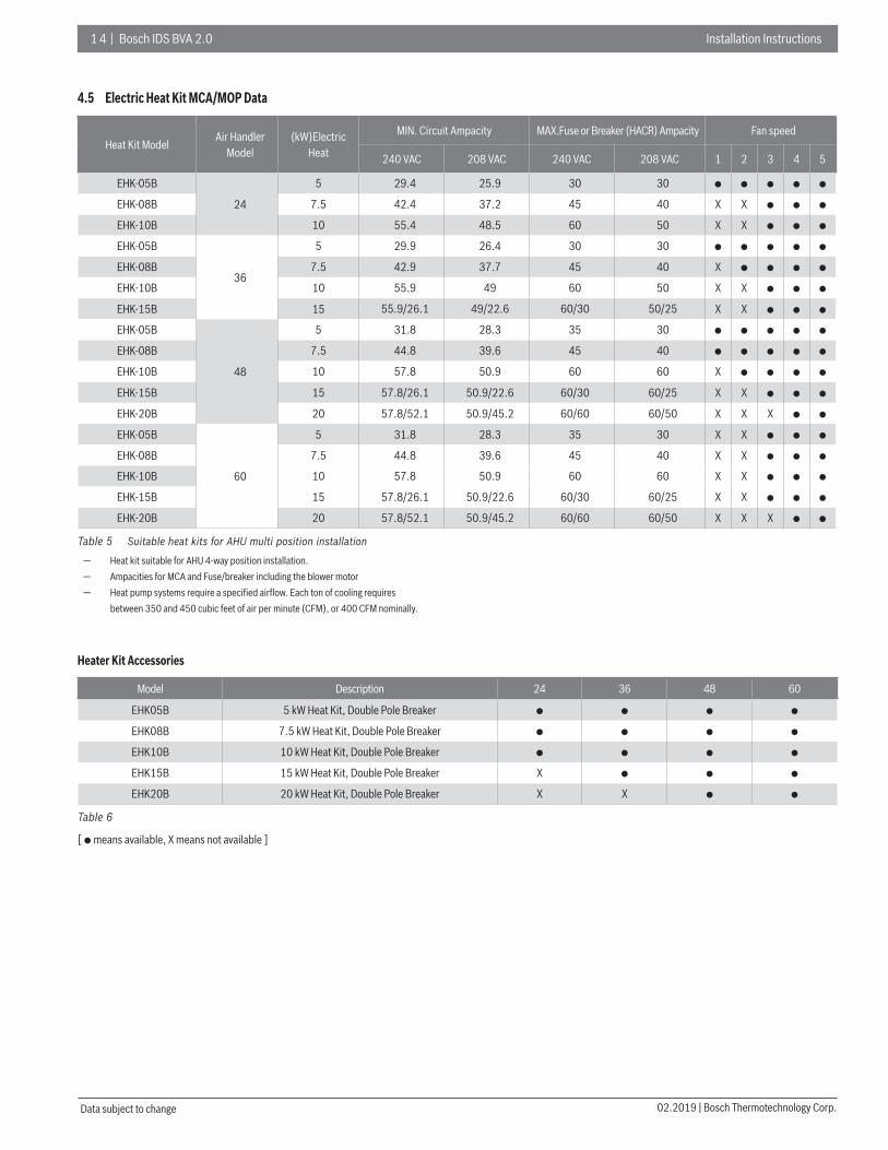
4.5 Electric Heat Kit MCA/MOP Data
Heat Kit ModelAir Handler
Model(kW)Electric
Heat
MIN. Circuit Ampacity MAX.Fuse or Breaker (HACR) Ampacity Fan speed
240 VAC 208 VAC 240 VAC 208 VAC 1 2 3 4 5
EHK-05B
24
5 29.4 25.9 30 30 ● ● ● ● ●
EHK-08B 7.5 42.4 37.2 45 40 X X ● ● ●
EHK-10B 10 55.4 48.5 60 50 X X ● ● ●
EHK-05B
36
5 29.9 26.4 30 30 ● ● ● ● ●
EHK-08B 7.5 42.9 37.7 45 40 X ● ● ● ●
EHK-10B 10 55.9 49 60 50 X X ● ● ●
EHK-15B 15 55.9/26.1 49/22.6 60/30 50/25 X X ● ● ●
EHK-05B
48
5 31.8 28.3 35 30 ● ● ● ● ●
EHK-08B 7.5 44.8 39.6 45 40 ● ● ● ● ●
EHK-10B 10 57.8 50.9 60 60 X ● ● ● ●
EHK-15B 15 57.8/26.1 50.9/22.6 60/30 60/25 X X ● ● ●
EHK-20B 20 57.8/52.1 50.9/45.2 60/60 60/50 X X X ● ●
EHK-05B
60
5 31.8 28.3 35 30 X X ● ● ●
EHK-08B 7.5 44.8 39.6 45 40 X X ● ● ●
EHK-10B 10 57.8 50.9 60 60 X X ● ● ●
EHK-15B 15 57.8/26.1 50.9/22.6 60/30 60/25 X X ● ● ●
EHK-20B 20 57.8/52.1 50.9/45.2 60/60 60/50 X X X ● ●
Table 5 Suitable heat kits for AHU multi position installation
— Heat kit suitable for AHU 4-way position installation. — Ampacities for MCA and Fuse/breaker including the blower motor — Heat pump systems require a specifi ed airfl ow. Each ton of cooling requires
between 350 and 450 cubic feet of air per minute (CFM), or 400 CFM nominally.
Heater Kit Accessories
Model Description 24 36 48 60
EHK05B 5 kW Heat Kit, Double Pole Breaker ● ● ● ●
EHK08B 7.5 kW Heat Kit, Double Pole Breaker ● ● ● ●
EHK10B 10 kW Heat Kit, Double Pole Breaker ● ● ● ●
EHK15B 15 kW Heat Kit, Double Pole Breaker X ● ● ●
EHK20B 20 kW Heat Kit, Double Pole Breaker X X ● ●
Table 6
[ ● means available, X means not available ]

Installation Instructions Bosch IDS BVA 2.0 | 15
Bosch Thermotechnology Corp. | 02.2019 Data subject to change
5 Airfl ow Performance
Airfl ow performance data is based on cooling performance with a coil and no fi lter in place. Check the performance table for appropriate unit size selection. External static pressure should stay within the minimum and maximum limits
Air Handler Model Size
Motor SpeedSCFM
External Static Pressure-Inches W.C.[kPa]0[0] 0.1[.02] 0.2[. 05] 0.3[.07] 0.4[.10] 0.5[.12] 0.6[.15] 0.7[.17] 0.8[.20]
24
Tap(5)SCFM 1181 1144 1104 1063 1021 991 961 919 902 Watts 263 274 283 289 298 304 314 323 328
Tap(4)-Default High Stage SettingSCFM 961 913 872 826 792 748 717 673 638 Watts 146 151 160 166 175 180 190 195 205
Tap(3)SCFM 852 797 760 708 674 626 589 535 500 Watts 109 114 122 127 137 142 150 155 157
Tap(2)-Default Low Stage Setting SCFM 755 711 653 615 563 505 499 413 382 Watts 81 98 94 103 108 112 119 125 133
Tap(1)SCFM 712 647 604 548 490 481 452 427 368 Watts 71 75 84 88 93 98 101 109 114
36
Tap(5)SCFM 1460 1420 1371 1329 1228 1224 1195 1093 1041 Watts 283 294 301 311 322 327 340 356 367
Tap(4)-Default High Stage SettingSCFM 1269 1213 1170 1121 1085 996 911 867 810 Watts 191 197 207 213 223 238 247 255 266
Tap(3)SCFM 1152 1093 1046 988 895 829 764 717 707 Watts 147 152 161 167 181 192 198 207 208
Tap(2)-Default Low Stage Setting SCFM 925 879 808 700 623 573 516 495 442 Watts 87 96 100 111 116 125 129 134 143
Tap(1)SCFM 889 727 456 225 / / / / /Watts 74 66 51 44 / / / / /
48
Tap(5)SCFM 2051 2006 1961 1914 1867 1819 1777 1735 1695 Watts 454 471 487 503 518 531 545 559 572
Tap(4)SCFM 1914 1875 1831 1782 1735 1691 1649 1611 1581 Watts 384 401 416 430 442 455 467 480 492
Tap(3)-Default High Stage SettingSCFM 1714 1661 1611 1560 1513 1469 1424 1380 1314 Watts 273 289 304 317 330 343 353 366 386
Tap(2)SCFM 1499 1451 1398 1340 1288 1247 1188 1058 993 Watts 198 212 224 234 243 256 271 290 303
Tap(1)-Default Low Stage Setting SCFM 1363 1307 1250 1181 1134 1062 938 875 835 Watts 151 163 175 181 193 206 224 232 243
60
Tap(5)SCFM 2029 1988 1947 1900 1858 1815 1771 1716 1671 Watts 466 482 498 514 528 541 553 565 572
Tap(4)-Default High Stage SettingSCFM 1881 1843 1800 1754 1708 1666 1626 1590 1558 Watts 391 407 423 438 449 462 474 487 498
Tap(3)SCFM 1677 1633 1586 1543 1499 1449 1409 1370 1281 Watts 281 297 311 325 338 346 358 370 386
Tap(2)-Default Low Stage Setting SCFM 1491 1439 1380 1334 1285 1246 1180 1047 988 Watts 205 217 226 238 250 259 269 292 300
Tap(1)SCFM 1348 1280 1227 1180 1130 1042 933 871 825 Watts 157 165 176 187 196 206 225 233 245
Table 7
Bold outlined areas represent airfl ow outside of the required 300-450 cfm/ton range.NOTES:1. The high stage airfl ow must be used as the rated airfl ow for the full load operation of machine. 2. The rated airfl ow of systems without electric heater kits requires between 300 and 450 cubic feet of air per
minute (CFM).3. The rated airfl ow of systems with electric heater kits requires between 350 and 450 cubic feet of air per
minute (CFM).4. The air distribution system has the greatest eff ect on airfl ow. Therefore, the contractor should use only
industry-recognized procedures.5. Duct design and construction should be carefully done. System performance can be lowered dramatically
through poor design or workmanship.6. Air supplier ducts should be located along the perimeter of the conditioned space and properly sized.
Improper location or insuffi cient air fl ow may cause drafts or noise in the ductwork.7. Installers should balance the air distribution system to ensure proper quiet airfl ow to all rooms in the
home. An air velocity meter or airfl ow hood can be used to balance and verify branch and system airfl ow (CFM).
shown in the table below in order to ensure proper operation of both cooling, heating, and electric heating operation.

1 6 | Bosch IDS BVA 2.0 Installation Instructions
02.2019 | Bosch Thermotechnology Corp.Data subject to change
5.1 Indoor Fan Motor Function
System operation and function
Two Stage Fan ControlThe IDS 2.0 IDU supports two stage fan control which requires a two stage thermostat (Y1&Y2). When there is a call for Y2, the blower motor will turn to high speed setting. When there is a call for Y1, the blower motor will turn to low speed setting. Unit will run at low speed setting when there is only G call. It will run in high speed setting when there is W/W1/W2 signal (when the electric heat kit is on).
The X13 ECM motor supports 5 speeds. Customer can select the suitable speed by adjusting the SW6-1 and SW6-2 dip switches. Refer to Airfl ow Performance Table (Table 7) for reference airfl ow. Refer to fi gure 23 for dip switches settings.
If 2 stage thermostat is not available, single stage thermostat may be used, please refer to Wiring Diagram section for wiring instructions. If Y1 and Y2 are jumped, the unit will only run in high stage fan speed.
Anti-Cold Air Fan DelayThe Anti-Cold Air Fan Delay function utilizies a sensor (T2) located on the indoor coil, which prevents the blower from turning on until the coil has reached a certain temperature. This feature prevents cold air blow during heating operation.
1. When SW6-3 dip switch is set to the "ON" position and the unit is in heating mode, the Anti-Cold Air Fan Delay function will activate based on the following entry conditions (all 3 conditions must be met):
a. Indoor Coil Temperature (T2) < 82.4℉
b. Electric heat kit is turned off
c. There is a call for Y1 from thermostat to indoor unit
2. This function will deactivate if ONE OF the following exit conditions are met OR the system has been operating in heating mode for 15 minutes.
a. T2 ≥ 89.6℉
b. Heater kit is turned on
c. The system is NOT running Heat mode
3. During the heating mode, if one of the exit conditions of Anti-Cold Air is satisfi ed, the blower motor will turn on in fi rst stage fan speed.
4. During the heating mode, if all of the entry conditions of Anti-Cold Air are met and maintained for 120s, the blower motor will change to fi rst stage speed.
Heating Fan DelayIf SW6-3 dip switch is set to the "OFF" position and the unit is in heating mode, the blower will operate with a 90 second delay with the fan speed dictated by Y1 or Y2 signal.
Passive Dehumidifi cation (Optional)IDS 2.0 IDU has a Passive Dehumidifi cation function which lowers the fan speed (fi rst stage) with a DH call from the thermostat. This function requires proper DH wiring from the indoor unit to the thermostat (with a humidistat).
If DH wire is not connected, the unit will still function normally.

Installation Instructions Bosch IDS BVA 2.0 | 17
Bosch Thermotechnology Corp. | 02.2019 Data subject to change
6 Ductwork
Field ductwork must comply with the National Fire Protection Association NFPA 90A, NFPA 90B and any applicable local ordinance(s).
WARNING: FIRE HAZARD AND CARBON MONOXIDE
Do not, under any circumstances, connect return ductwork to any other heat producing device such as fireplace insert, stove, etc. Unauthorized use of such devices may result in fire, carbon monoxide poisoning, explosion, personal injury or property damage.
Sheet metal ductwork run in unconditioned spaces must be insulated and covered with a vapor barrier. Fibrous ductwork may be used if constructed and installed in accordance with SMACNA Construction Standard on Fibrous Glass Ducts. Ductwork must comply with National Fire Protection Association as tested by U/L Standard 181 for Class I Air Ducts. Check local codes for requirements on ductwork and insulation.
Duct system must be designed within the range of external static pressure the unit is designed to operate against. It is important that the system airflow be adequate. Make sure supply and return ductwork, grills, special filters, accessories, etc. are accounted for in total resistance. See airflow performance tables in Section 5 of this manual.
Design the duct system in accordance with “ACCA” Manual “D” Design for Residential Winter and Summer Air Conditioning and Equipment Selection. Latest editions are available from: “ACCA” Air Conditioning Contractors of America, 1513 16th Street, N.W., Washington, D.C. 20036. If duct system incorporates flexible air duct, be sure pressure drop information (straight length plus all turns) shown in “ACCA” Manual “D” is accounted for in system.
Supply plenum should be attached to the 3/4” duct flanges supplied with the unit. Attach flanges around the blower outlet.
If an elbow is included in the plenum close to the unit, it must not be smaller than the dimensions of the supply duct fl ange on the unit.
The front flange on the return duct (if connected to the blower casing) must not be screwed into the area where the power wiring is located. Drills or sharp screw points can damage insulation on wires located inside unit.
Secure the supply and return ductwork to the unit flanges, using proper fasteners for the type of duct used and tape the duct-to-unit joint as required to prevent air leaks.

1 8 | Bosch IDS BVA 2.0 Installation Instructions
02.2019 | Bosch Thermotechnology Corp.Data subject to change
7 Refrigerant Connections
Keep the coil connections sealed until refrigerant connections are made. Refer to the BOVA Installation, Operation, and Maintenance Manual for details on line sizing, tubing installation, and charging information.
Coil is factory charged with Nitrogen. Evacuate the system before charging with refrigerant.
Install refrigerant lines so that they do not block service access to the front of the unit.Nitrogen should fl ow through the refrigerant lines while brazing.
Use a brazing shield to protect the cabinet’s paint and a wet rag to protect the rubber grommet and input pipe’s piston seal ring from being damaged by torch fl ames. Use a wet rag or an approved heat paste to protect the TXV sensing bulb during the brazing process. Refer to Figure 13.
After the refrigerant line connections are made, seal the gap around the connections with pressure sensitive gasket.
Figure 13
Vapor line
Liquid line
Wet rag
Use a wet rag to protect the sealing rings in the input pipe from being damaged by torch flames while brazing.
After the brazing work is fi nished, make sure to check that there is no refrigerant leakage. After checking for vapor leaks, be sure to insulate the pipe connections, refer to Figure 14.
Figure 14
Do not leave a gap
Do not leave a gap
Vapor line
Piping heat insulationmaterial
Liquid line
Air handler
7.1 Condensate Drain Connection
Consult local codes for specifi c requirements.
Refer to Figure 15 and the information below for required condensate drain trap installation.
Figure 15
CONDENSATE DRAIN TRAP
DO NOT OVERTIGHTEN DRAIN FITTING
TOWARDS DRAIN CONNECTION UNIT MUST BE SLIGHTLY INCLINED
3"3"3"
UNIT
TO APPROVED DRAIN
DO NOT OPERATE UNIT WITHOUT CONDENSATE DRAIN TRAP.
1. When making drain fi tting connections to the drain pan, use a thin layer of Tefl on paste, silicone or Tefl on tape and install by hand tightening.
2. When making drain fi tting connections to drain pan, do not overtighten. Over tightening fi ttings can split pipe connections on the drain pan.
Ensure drain lines do not block access to front of the unit. Minimum clearance of 24 inches is required for filter, coil or blower removal and service access.
Make sure unit is leveled or pitched slightly toward primary drain connection so that water will drain completely from the pan.
Do not reduce drain line size to less than connection size provided on condensate drain pan.
All horizontal drain lines must be pitched downward away from the unit at a minimum of 1/8” per foot of line to ensure proper drainage.
Do not connect condensate drain line to a closed or open sewer pipe. Run condensate to an open drain or run line to a safe outdoor area.
The drain line should be insulated where necessary to prevent sweating and damage due to condensate forming on the outside surface of the line.
Make provisions for disconnecting and cleaning of the primary drain line should it become necessary. Install a 3 inch trap in the primary drain line as close to the unit as possible. Make sure that the top of the trap is below connection to the drain pan to allow complete drainage of pan (See Figure 15).

Installation Instructions Bosch IDS BVA 2.0 | 19
Bosch Thermotechnology Corp. | 02.2019 Data subject to change
Auxiliary drain line should be run to a place where condensate will be noticeable. Homeowner should be warned that a problem exists if water should begin running from the auxiliary drain line.
Plug the unused drain connection with the plugs provided in the parts bag provided with the unit. Use a thin layer of teflon paste, silicone or teflon tape to form a water tight seal.
Test condensate drain pan and drain line after installation is complete. Pour water into drain pan, enough to fill drain trap and line. Check to ensure drain pan is draining completely, no leaks are found in drain line fittings, and water is draining from the termination of the primary drain line.
8 Air Filter (Not Factory-Installed)
Filters are not included with the unit and must be fi eld supplied.
An external fi lter or other means of fi ltration must be properly sized for a maximum of 300 feet/min. air velocity or what is recommended for the type of fi lter installed.
Filter application and placement are critical to airfl ow, which may aff ect the heating and cooling system performance. Reduced airfl ow can shorten the life of the system’s major components, such as motor, elements, heat relays, evaporator coil or compressor. Consequently, we recommend that the return air duct system have only one fi lter location. For systems without a return air fi lter grill, multiple fi lter grills can be installed at each of the return air openings.
If adding high effi ciency fi lters or electronic air fi ltration systems, it is very important that the air fl ow is not reduced. If air fl ow is reduced the overall performance and effi ciency of the unit will be reduced. It is strongly recommended that a professional installation technician is contacted to ensure such fi ltration systems are installed correctly.
Do not double fi lter the return air duct system. Do not fi lter the supply air duct system. This will change the performance of the unit and reduce airfl ow.
WARNING: FIRE HAZARD
Do not operate the system without filters. A portion of the dust suspended in the air may temporarily lodge in the duct runs and at the supply registers. Any circulated dust particles could be heated and charred by contact with the air handler elements. This residue could soil ceilings, walls, drapes, carpets and other articles in the house. Soot damage may occur with filters in place, when certain types of candles, oil lamps or standing pilots are burned.
2 0 | Bosch IDS BVA 2.0 Installation Instructions
02.2019 | Bosch Thermotechnology Corp.Data subject to change
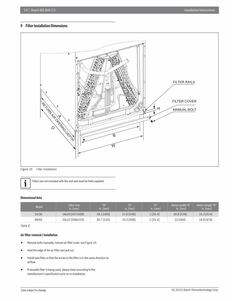
9 Filter Installation Dimensions
Figure 16
FILTER RAILS
FILTER COVER
MANUAL BOLT
RETURN AIR OPENING DEPTH
W
B
A
D
H
Filter Installation
Filters are not included with the unit and must be fi eld supplied.
Dimensional data
Model Filter SizeIn. [mm]
"W" In. [mm]
"D" In. [mm]
"H" In. [mm]
Return width "A" In. [mm]
Return length "B" In. [mm]
24/36 18x20 [457x508] 18.3 [466] 21.6 [548] 1 [25.4] 20.8 [528] 16.3 [414]
48/60 20x22 [508x559] 20.7 [526] 23.9 [608] 1 [25.4] 23 [584] 18.8 [478]
Table 8
Air fi lter removal / installation
Remove bolts manually, remove air filter cover, see Figure 16.
Hold the edge of the air filter and pull out.
Install new filter so that the arrow on the filter is in the same direction as airflow.
If reusable filter is being used, please clean according to the manufacturer's specification prior to re-installation.

Installation Instructions Bosch IDS BVA 2.0 | 21
Bosch Thermotechnology Corp. | 02.2019 Data subject to change
10 Maintenance
For continuing high performance and to minimize possible equipmentfailure, periodic maintenance must be performed on this equipment.
10.1 Cleaning Precautions
WARNING:
Any unit repairs must be performed by qualified service personnel only.
WARNING: BEFORE CLEANING AND MAINTENANCE
Always turn off your heat pump and disconnect its power supply before cleaning or maintenance.
CAUTION:
When removing filter, do not touch metal parts in the unit. The sharp metal edges can cut you.
NOTICE:
Do not use chemicals or chemically treated cloths to clean the unit .
Do not use benzene, paint thinner, polishing powder or other solvents to clean the unit.
Do not operate the system without a filter in place
10.2 Regular Maintenance
Your heat pump must be inspected regularly by a qualifi ed service technician. Your annual system inspection must include:
1. Inspect the air fi lter every ninety days or as often as needed. If blocked or obstructed, clean or replace at once.
2. Inspection and/or cleaning of the blower wheel housing and motor.
3. Inspection and cleaning of indoor and outdoor coils as required.
4. Inspection and/or cleaning of the indoor coil drain pan and drain lines, as well as auxiliary drain pan and lines.
5. Check all electrical wiring and connections. Correct as needed, referring to the wiring diagram.

2 2 | Bosch IDS BVA 2.0 Installation Instructions
02.2019 | Bosch Thermotechnology Corp.Data subject to change
11 Wiring Diagrams
WARNING: ELECTRICAL SHOCK
Disconnect all power before servicing or installing this unit. Multiple power sources may be present. Failure to do so may cause property damage, personal injury or death.
DANGER: ELECTRICAL SHOCK
This unit must be properly grounded and protected by a circuit breaker or fuse.
WARNING: ELECTRICAL SHOCK
These units must be wired and installed in accordance with all National and Local Safety Codes.
To avoid electrical shock, please ensure: — The heat pump is properly grounded — The main power plug to the heat pump has been joined with the
ground wiring (DO NOT ALTER THIS).
Do not strain the power wiring.
Dashed lines in the following thermostat wiring diagrams refer to optional wiring (wiring for Passive Dehumidifi cation Function and/OR Electric Heat). For thermostat wiring please refer to the Owner’s Manual of the thermostat.
Figure 17
Y2
W/E
C
Y
C G
TH ERM OSTAT
INDOOR UNIT OUTDOOR UNIT
G
Y2
R
O/B
H/DH
W2W1 C Y B WBDh Y1R
GRA
Y
PURP
LE
BRO
WN
BLUE
GRE
EN
RED
YELL
OW
WHI
TE
Support 3H and 2C thermostat
WHI
TE/B
LACK
BRO
WN
YELL
OW
BLUE
WHI
TE
Note: Any time the electric heat elements are active, the indoor fan will run in high stage.
Control Wiring For HP Systems
Dh wiring is optional and requires a thermostat with a humidistat. Dh functions as Passive Dehumidifi cation and will downstage the indoor fan to fi rst stage. System will operate according to normal sequence of operations if Dh wiring is absent.

Installation Instructions Bosch IDS BVA 2.0 | 23
Bosch Thermotechnology Corp. | 02.2019 Data subject to change
Figure 18
Y2
W/E
C
Y
C G
T H E R M O S T A T
INDOOR UNIT OUTDOOR UNIT
G
R
O/B
H/DH
W2W1 C Y B WBDh Y1R
Wiring for 4H and 2C thermostat
W2
GRA
Y
PURP
LE
BRO
WN
BLUE
GRE
EN
RED
YELL
OW
WHI
TE
WHI
TE/B
LACK
BRO
WN
YELL
OW
BLUE
WHI
TE
Y2
Note: Any time the electric heat elements are active, the indoor fan will run in high stage.
Control Wiring For HP Systems
Figure 19
Y2
W/E
C
Y
C G
THERMOSTAT
INDOOR UNIT OUTDOOR UNIT
G
R
O/B
H/DH
W2W1 C Y B WBDh Y1R
GRA
Y
PURP
LE
BRO
WN
BLUE
GRE
EN
RED
YELL
OW
WHI
TE
Wiring for 3H and 1C thermostat
WHI
TE/B
LACK
BRO
WN
YELL
OW
BLUE
WHI
TE
W2
Note: Because Y1 and Y2 are jumped, the indoor fan will only run in high stage.
Note: Any time the electric heat elements are active, the indoor fan will run in high stage.
Control Wiring For HP Systems

2 4 | Bosch IDS BVA 2.0 Installation Instructions
02.2019 | Bosch Thermotechnology Corp.Data subject to change
Figure 20
Wiring for 2H and 2C thermostat
Note: Any time the electric heat elements are active, the indoor fan will run in high stage.
Y2
C
Y
C G
THERMOSTAT
INDOOR UNIT OUTDOOR UNIT
G
R
O/B
H/DH
W2W1 C Y B WBDh Y1R
GRA
Y
PURP
LE
BRO
WN
BLUE
GRE
EN
RED
YELL
OW
BRO
WN
YELL
OW
BLUE
Y2
Control Wiring For HP Systems
Figure 21
Wiring for 1H and 1C thermostat
Y2
C
Y
C G
THERMOSTAT
INDOOR UNIT OUTDOOR UNIT
G
R
O/B
H/DH
W2W1 C Y B WBDh Y1R
GRA
Y
PURP
LE
BRO
WN
BLUE
GRE
EN
RED
YELL
OW
BRO
WN
YELL
OW
BLUE
Note: Because Y1 and Y2 are jumped, the indoor fan will only run in high stage.
Control Wiring For HP Systems

Installation Instructions Bosch IDS BVA 2.0 | 25
Bosch Thermotechnology Corp. | 02.2019 Data subject to change
Figure 22
Wiring for 2H and 1C thermostat
Y2
C
Y
C G
THERMOSTAT
INDOOR UNIT OUTDOOR UNIT
G
R
O/B
H/DH
W2W1 C Y B WBDh Y1R
GRA
Y
PURP
LE
BRO
WN
BLUE
GRE
EN
RED
YELL
OW
BRO
WN
YELL
OW
BLUE
W/E
WHI
TE/B
LACK
WHI
TE
WHI
TE
Note: Because Y1 and Y2 are jumped, the indoor fan will only run in high stage.
Note: W1 and W2 are jumped, so Electric Heat will only function in high stage.
Control Wiring For HP Systems
Electric wiring gauge for H/P systems
Model(Btu/h) 24 36 48 60
PowerPhase Single
Voltage/frequency 208/230VAC, 60Hz
LineGauge
Input Current Fuse Indoor unit (A) 15A 15A 15A 15A
Indoor Unit Power Line
Line Quantity 3 3 3 3
Line Diameter (AWG) 14 14 14 14
Outdoor Unit Power Line
Line Quantity 3 3 3 3
Line Diameter (AWG) 14 12 10 10
Outdoor -Indoor Signal Line
Line Quantity 4 4 4 4
Line Diameter (AWG) 18 18 18 18
Thermostat Signal Line
Line Quantity 5 5 5 5
Line Diameter (AWG) 18 18 18 18
Table 9

2 6 | Bosch IDS BVA 2.0 Installation Instructions
02.2019 | Bosch Thermotechnology Corp.Data subject to change
Figure 23
COM208V240V
WHITE/BLACK
W2
CN
35C
N33
CN
4
CN
5
DETAILED REFERENCEMANUAL INSTRUCTIONS
SPEED TAPS
WH
ITE
GR
AY
BLU
E
MEDIUM LOW
LOW
MEDIUM
MEDIUM HIGH
HIGH
BW1
Y2
GR
EE
N
RE
D
YE
LLOW
RC Y1
PU
RP
LE
BR
OW
N
CN
38
CN
39
L1-A
L1-B
CN
36
T2 OPEN
LED
4INDOOR MAIN BOARD
SW6-1,2
SW6-3
NORMAL
HEAT:FAN DELAY START
HEAT:ANTI-COLD AIR
FAN DELAY
POWER ON
ON
3
C
CN
6 G
SCHEMATIC DIAGRAM
SEE RATING PLATE FOR VOLT&HERTZ
FIELD POWER WIRING
54
32
1C
HEATER KIT PLUG
GR
OU
ND
POWER IN
6
SW
6
BLACK
BLA
CK
RED
RE
D
RED
NOTES:NOTES:1: If connected to 1-Stage thermostat jump Y1 and Y2. 1: If connected to 1-Stage thermostat jump Y1 and Y2. 2: Use copper wire (752: Use copper wire (75℃ ℃ min) only between disconnect switch and unit .min) only between disconnect switch and unit .3: Rewired in accordance with NEC and local codes.3: Rewired in accordance with NEC and local codes.4: If any of the original wire, as supplied, must be replaced use the same or 4: If any of the original wire, as supplied, must be replaced use the same or equivalent type wire. equivalent type wire. 5: Connect R to R,G to G,Y1 to Y,etc.See outdoor instruction for details.5: Connect R to R,G to G,Y1 to Y,etc.See outdoor instruction for details.6: If some signal lines of CN4 and CN5 are not used, wrap them up 6: If some signal lines of CN4 and CN5 are not used, wrap them up separately with CAP. separately with CAP.7: See airflow tables for airflow settings.7: See airflow tables for airflow settings.8: : When need to change the transformer stage, remove the lead from “240V”When need to change the transformer stage, remove the lead from “240V” terminal and then connect the lead to “208V”terminal. terminal and then connect the lead to “208V”terminal.
ON
ON
ON
ON
SW6-4
1 2
ON
CAUTION:NOT SUITABLE FOR USE ON SYSTEMS EXCEEDING 150V TO GROUND. .
24V
WH
ITE
YE
LLOW
BLU
E
PU
RP
LE
GR
EE
N
ANTI-COLD AIR FAN DELAY
TRANSFORMER
FAN
GREEN LED4 FLASHWORKING
5 T2 TEMPERATURE SENSOR FAULT/
DEHUMIDIFICATION1 /
NORMAL
BR
OW
N
W2
W1
Dh
Y1+Y2 OR WY1 OR G
1
1
2
3
2
3
4
5
*FACTORY DEFAULT
RESERVED
FAN SPEED TAPS
*
*
*
3
ON
4ON
4
ON
1 OFF1
YELLOW 1 2
1 2
1 2
1 2
ON
3
Switch ON Position:Color upper half to showswitch position is UP.
Switch OFF Position:Color upper half to showswitch position is DOWN.
ANTI-COLD AIR FAN DELAY
Indoor Unit Wiring Diagram

Installation Instructions Bosch IDS BVA 2.0 | 27
Bosch Thermotechnology Corp. | 02.2019 Data subject to change
United States and Canada
Bosch Thermotechnology Corp.65 Grove StreetWatertown, MA 02472
Tel: 866-642-3198Fax: 954-776-5529www.boschheatingandcooling.com
BTC 761701106 A / 02.2019


