6.0 REPAIRS USING ENCLOSURES (BOXES)...........................................................................................11 6.1 OVERVIEW...........................................................................................................................................11 6.2 PIPE AND PIPE FITTING ENCLOSURES...........................................................................................11 6.3 VALVE ENCLOSURES........................................................................................................................12 6.4 EXPANSION JOINT ENCLOSURES...................................................................................................12
7.0 REPAIRS TO VALVES ............................................................................................................................13 7.1 VALVE PACKING LEAKS ...................................................................................................................13 7.2 VALVE SEAT LEAKS ..........................................................................................................................14 7.3 PRESSURE SEAL BONNET LEAKS..................................................................................................14
8.0 TUBE CRIMPING.....................................................................................................................................15 8.1 OVERVIEW...........................................................................................................................................15 8.2 GENERAL REQUIREMENTS ..............................................................................................................15
9.0 DOCUMENTATION AND RECORD RETENTION ..................................................................................15 9.1 REQUIREMENTS FOR NEW LEAK REPAIR DEVICES (LRD)..........................................................15 9.2 RECORDS RETENTION ......................................................................................................................16
14.0 INSPECTION........................................................................................................................................20 14.1 GENERAL REQUIREMENTS...........................................................................................................20
Toledo Refinery
Site Technical Practices EP 5-11-3
On-Stream Leak Repairs of Piping Components
August 2007 Revision 0.0
Page 2 of 54
Maintained by E2G – Shaker Heights, OH
14.2 INSPECTION OF NEW LEAK REPAIR DEVICES (LRDS) .............................................................20 14.3 INSPECTION PRIOR TO INSTALLATION OF A LEAK REPAIR DEVICE (LRD)..........................20
15.0 INSTALLATION OF ON–STREAM LEAK SEALING DEVICES.........................................................21 15.1 OWNER RESPONSIBILITIES ..........................................................................................................21 15.2 LEAK REPAIR CONTRACTOR RESPONSIBILITIES.....................................................................21 15.3 STOP GAP REPAIRS.......................................................................................................................22 15.4 REQUIREMENTS FOR BOLTING ...................................................................................................22 15.5 SEALANT REINJECTION ................................................................................................................22
16.0 DATA SHEET INSTRUCTIONS...........................................................................................................22 16.1 GENERAL.........................................................................................................................................22 16.2 INSTRUCTIONS FOR EP 5–11–3 DS..............................................................................................22 16.3 PART I - OWNER SUPPLIED INFORMATION:...............................................................................23 16.4 PART II - LEAK REPAIR CONTRACTOR (LRC) SUPPLIED INFORMATION...............................23 16.5 PART III - DESIGN/INSTALLATION REVIEW, OWNER’S ENGINEER .........................................24 16.6 PART IV - LRD REMOVAL AND REPAIR, OWNER’S ENGINEER................................................24
1.1 This Practice covers requirements for performing on–stream repairs to leaking piping components such as flanges, pipe and pipe fittings, expansion joints and valves. In addition, the on–stream repairs for pipe flanges in this Practice can also be used for pressure vessel nozzle and girth flanges.
1.2 Any deviation to this Practice shall be in accordance with the procedure given in EP 1-1-3.
1.3 An Asterisk (*) indicates that a decision by the Owner’s Engineer or Owner is required, or that additional information is furnished by the Purchaser.
2.0 REFERENCES
The latest edition of the following standards and publications are referred to herein. STANDARDS AND PUBLICATIONS
Site Technical Practices
EP 1–1–3 Deviations to Site Technical Practices EP 5–5–2 Welding Requirements for Piping EP 5–5–3 Piping Erection and Testing EP 5–5–4 Bolting Procedures for Flanged Connections EP 5–6–2 Piping for Rotating Equipment EP 5–7–1 Hot Taps EP 5–11–3 DS On–Stream Leak Repairs of Piping Components Data Sheet EP 7–1–5 Welding Requirements for Pressure Vessels EP 10–2–1 Material Requirements for Aggressive Environmental Services EP 10–2–3 Material Hardness Requirements EP 15–1–4 Positive Materials Identification (PMI)
ASME Code
Sec. III Rules for Construction of Nuclear Power Plant Components Sec. VIII Pressure Vessels, Division 1 B16.5 Pipe Flanges and Flanged Fittings NPS ½ Through NPS 24 B31.3 Process Piping
ASTM Specifications
A193 Standard Specification for Alloy–Steel and Stainless Steel Bolting Materials for High Temperature Service or High Pressure Service and Other Special Purpose Applications
3.0 DEFINITIONS
3.1 Aggressive Environmental Service (AES) - Process services which result in material degradation such as cracking, scaling, blistering, and severe pitting and/or corrosion. Examples of such services are hydrogen service, wet hydrogen sulfide, cyanides, caustic, amine, and hydrofluoric acid. AES process fluid are defined in EP 10-2-1
Toledo Refinery
Site Technical Practices EP 5-11-3
On-Stream Leak Repairs of Piping Components
August 2007 Revision 0.0
Page 4 of 54
Maintained by E2G – Shaker Heights, OH
3.2 Category D Fluid Service - A fluid service in which all the following apply: 1) The fluid handled is nonflammable, nontoxic and not damaging to human tissues as defined in
ASME B31.3, paragraph 300.2. 2) The design gage pressure does not exceed 150 psig. 3) The design temperature is from –20°F through 366°F.
3.3 Certificates of Compliance - A document by which the material manufacturer (or Seller to the extent that the Code allows) certifies that the material represented has been produced and tested in accordance with the requirements of the basic material specification shown on the certificate. Objective evidence of compliance with the requirements of the material specification shall be maintained in the records of the material manufacturer. However, certificates of compliance shall include reports or results of tests required by the material specification or the Order.
3.4 Certified Material Test Report (CMTR) - A document, or documents, on which are recorded the results of tests, examinations, repairs, or treatments required by the Material Specification. Supplementary or special requirements, in addition to the requirements of the Material Specification, as required by the Purchase Order shall also be included on the CMTR. The specification of the material being represented including the year of issue, and the material heat number shall also be included on the CMTR. All such documents shall identify the applicable Material Specification and shall be identified to the material represented.
3.5 Inspector - A Toledo Refinery appointed engineer or inspector.
3.6 Leak Repair Contractor (LRC) - The company or business that agrees to furnish materials and personnel at a specified price and/or rate to the Owner in order to perform an on–stream leak repair.
3.7 Leak Repair Device (LRD) - A generic term used to describe a component that is utilized to seal an on–stream leak on a piece of equipment or piping. This device may be a standard clamp design offered by many manufacturers or a customized fabricated clamp, box, or other enclosure.
3.8 Mainlining - A term used to describe seepage of sealant into the process stream during the sealant injection phase of a LRD installation. Introduction of sealant into the process stream may cause problems with valves and instruments; therefore, the potential of seepage must be minimized.
3.9 Manufacturer - The recipient of a direct or indirect purchase order for materials and/or equipment. In this context, a direct order is one issued to a manufacturer by a contractor or the Owner. An indirect order is one issued to a manufacturer by a vendor (recipient of a direct order) for materials, fabricated components, or subassemblies.
3.10 On–Stream - Equipment containing any amount of a process fluid including Category D Services.
3.11 Owner - The Toledo Refinery.
3.12 Owner’s Engineer - A Toledo Refinery appointed engineer.
3.13 Repair - The work necessary to restore piping to a condition suitable for safe operation at the design conditions. If any restorative changes result in a change of design pressure and temperature, the requirements for Rerating shall also be satisfied.
3.14 Temporary Repair - Repairs made to components in order to restore sufficient integrity to continue safe operation until permanent repairs can be made and accomplished within a time frame acceptable to the Inspector or Owner’s Engineer.
Toledo Refinery
Site Technical Practices EP 5-11-3
On-Stream Leak Repairs of Piping Components
August 2007 Revision 0.0
Page 5 of 54
Maintained by E2G – Shaker Heights, OH
4.0 GENERAL REQUIREMENTS
4.1 (*)To control and eliminate leaks or prevent leaks at locally thinned areas in pressurized piping components that are in service, on–stream repair may be made by utilizing the repair techniques in this Practice. All of these techniques are considered temporary in nature. Other repair techniques not specially cited in this Practice may be used if approved by the Owner’s Engineer.
4.2 (*)During the next turnaround or other appropriate opportunities, all leak sealing and leak dissipating devices, excluding packing repairs made to valves, shall be removed and appropriate actions made to restore the original integrity of the component. Valve packing repairs shall be evaluated on a case–by–case basis to determine if re-packing or valve replacement is required. The Inspector shall insure that the leak seal or dissipating device is removed and repairs are made, and the Owner’s Engineer shall be involved in determining appropriate repair methods and procedures.
4.3 Drilling holes for the purpose of sealant injection into valve bodies, pipe fittings, or other components will be permitted only after review and approval of the Owner’s Engineer. The LRC shall prepare calculations to verify that the drilled holes will not threaten the integrity of the component and submit the calculations to the Owner’s Engineer for approval prior to drilling activity.
4.4 All hydraulic sealant injection pumps shall have a calibrated pressure gauge to indicate the hydraulic pressure required to inject the sealant. The LRC shall determine maximum sealant injection pressures for each leak to protect piping components from damage during the repair process.
5.0 REPAIRS OF FLANGE LEAKS
5.1 Overview
5.1.1 Flange clamps can be used to achieve an on–stream repair to a leaking flange. Alternatively, other procedures such as wire wrapping and flange bands can also be used to seal leaks depending on the operating conditions.
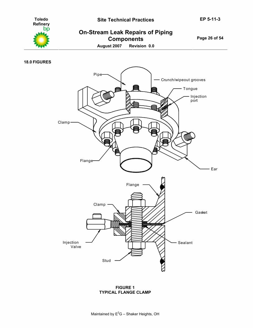
5.1.2 Flange clamps are split rings designed to encircle the flange, see Figure 1. The clamp is installed by bolting the two halves of the clamp together. The clamp then forms a sealant cavity between the flange faces and provides the means of injection of sealant through injection ports in the clamp ring.
5.1.3 The design of the clamp includes a seal on the inside of the ring. The seal is designed to make contact with the flange when the clamp halves are bolted together. The purpose of the seal is to contain the sealant and prevent extrusion during injection. The sealant can then fill the sealant cavity and seal off the leak completely.
5.1.4 There are two distinctly different designs of flange clamps: the insert clamp and the peripheral (outside diameter fitting) clamp. The size of the gap between the two flanges is the primary determining factor in selecting the type of clamp. Peripheral clamps are used where the flange gap is insufficient to accommodate an insert clamp blade or tongue.
5.1.5 The insert clamp is manufactured to fit precisely in the gap between the flanges. Some key advantages to this type of clamp are: • Little or no mechanical work is required on the flange. Flange studs change–out is not typically
required, injection holes need not be drilled into the flange, and little or no peening is required. • Being manufactured to fit, the clamp can be tolerant of flange misalignment, out–of–roundness,
or differing diameters. • Many applications permit the use of standard clamp rings held in readiness in a finished or
semi–finished state, requiring that only the insert be machined to the measured gap size.
Toledo Refinery
Site Technical Practices EP 5-11-3
On-Stream Leak Repairs of Piping Components
August 2007 Revision 0.0
Page 6 of 54
Maintained by E2G – Shaker Heights, OH
• Clamps are self–relieving and will vent should flange separation take place as a result of bolt relaxation. As the relaxation occurs, the leak will probably restart and serve as a warning that additional actions are necessary.
• The quantity of sealant is reduced. • Pressurized area between flanges is reduced. • A high degree of success has been experienced.
5.1.6 Peripheral clamps can be used as a simple ring to enclose the outside of the flanges with injection ports through the ring. The outside of the flanges can also be enclosed with packing that is compressed onto the flange periphery when the bolts on the clamp split line are tensioned. Additionally, these clamps are frequently used in conjunction with a low–viscosity compound to establish a homogeneous molding within the narrow flange gap. The major advantages of the peripheral clamp are: • The clamp can be used for narrow gap flanges where an insert clamp is impractical. • The technique requires fewer injection points when used with low viscosity compound. • Leak sealant work on site is reduced. • No drilling or peening of flange surfaces is required.
5.1.7 Peripheral clamps require careful and accurate flange measures, and subsequent marking to correct flange misalignment. Also, because there is not direct means of pressure release, it is advisable to check the ability of the joint fasteners to withstand full–line pressure over the total flange area. The maximum injection pressure should be analyzed by the LRC in relation to bolt stress to ensure that overloading does not occur.
5.1.8 High tensile strength flange bolting (A193 Grade B7 or B16) is known to be susceptible to stress corrosion cracking. The bolting in flanges in services that can contribute to stress corrosion cracking should be replaced with new bolting before injection of sealant. Similarly, bolting which has been previously encapsulated in sealant or when a corrosive service leak has recurred should be replaced with new bolting prior to re–injection of additional sealant. The replacing of the bolting shall be reviewed and approved by the Owner’s Engineer. If required, the replacing of the bolting on–stream shall be in accordance with EP 5-5-4
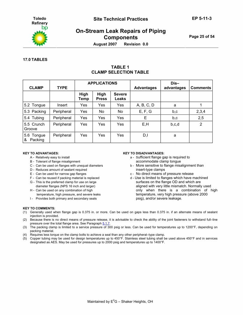
5.1.9 An overview of the attributes of the various clamps described below is given in Table 1. Numbers appearing before the name of each clamp in Table 1 refer to the paragraph numbers below.
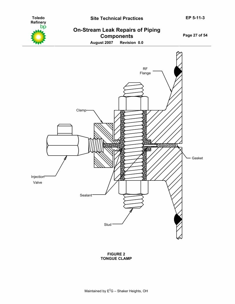
5.2 Tongue Clamp
5.2.1 A tongue clamp is an insert clamp type that is generally used for sealing leaks when the flange gap is 0.375 inches or more, see Figure 2. It can be used on gaps less than 0.375 inches, but an alternate means of sealant injection such as injection nuts or rings must be provided. These clamps have a high rate of success for sealing flange leaks on very high temperature, high pressure and high velocity leaks. They are relatively easy to install since the tongue aligns the clamp to the flange during installation.
5.2.2 The crunch teeth on the tongue are not designed for an interference fit but are designed to achieve metal to metal contact with the flange faces. The bore of the clamp ring does not contact the flange outside diameter. Therefore, this type of clamp can compensate for flange mismatch or out of roundness of the flange outside diameter. In addition, tongue clamps can be used on flanges that have unequal diameters.
5.2.3 The tongue clamp seal is created with the crunch teeth against the flange faces and extends down to the flange stud. This feature results in a reduction of the amount of sealant required to fill the cavity and seal the leak.
Toledo Refinery
Site Technical Practices EP 5-11-3
On-Stream Leak Repairs of Piping Components
August 2007 Revision 0.0
Page 7 of 54
Maintained by E2G – Shaker Heights, OH
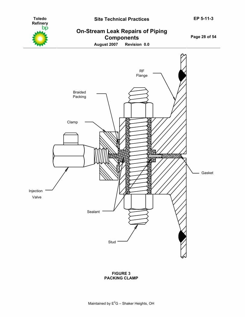
5.3 Packing Clamp
5.3.1 The packing clamp is a periphery clamp type which utilizes square braided packing installed in the inside diameter of the clamp ring, see Figure 3. The packing is compressed as the clamp halves are drawn tightly together and seals on the outside diameter of the flanges. The sealant then bridges against the packing when injected. Again the bore of the clamp ring does not contact the outside diameter of the flange.
5.3.2 The packing clamp is limited in use to a service pressure of 300 psig and less. It is not used on severe leaks because the high velocity of the leak may roll the packing out of the packing groove. The service temperature of the packing clamp is limited by the packing material. Typical packing materials are limited to approximately 1200°F to 1300°F.
5.3.3 The packing clamp is preferred on large diameter flanges (sizes NPS 16 and larger) since less bolt torque is required to achieve a seal than for any other type peripheral clamp. The packing size and extent of compression is necessary to compensate for mismatch and surface irregularities at the flange outside diameter.
5.3.4 This clamp can be reused if the packing material is replaced after each use.
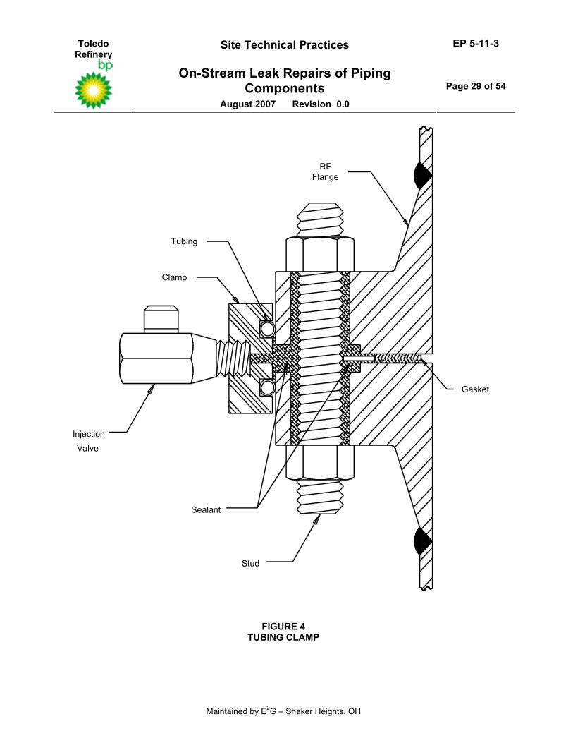
5.4 Tubing Clamp
5.4.1 The tubing clamp is a periphery type clamp where metal tubing is used rather than packing to achieve a seal, see Figure 4.
5.4.2 The clamp is normally used at pressures above 300 psig, but is also used at lower pressures when leakage is severe. The maximum service pressure is limited to approximately 2000 psig.
5.4.3 A greater clamp bolt torque is required to compress and achieve a seal than that required to compress packing. For this reason, a soft tubing is typically used for the peripheral seal.
5.4.4 (*)Copper tubing may be used as a standard for design temperatures up to a maximum of 450°F. Stainless steel tubing shall be used for design temperatures above 450°F and for all clamps installed on services which are categorized to be in AES, unless otherwise specified by the Owner’s Engineer. Tubing clamps may be used at temperatures as high as 1500°F, depending on the limits of the tubing material used.
5.4.5 All tubing shall be connected to the clamp (silver brazing, tack welding or equal) to insure that the tubing will not become dislodged while attempting to seal leaks with a high velocity.
5.4.6 As with packing, the size of tubing used depends on the size of the clamp and the amount of mismatch or surface irregularity measured by the LRC.
5.4.7 This clamp can also be reused if the tubing is removed, the clamp cleaned, and new tubing installed per paragraph 5.4.5.
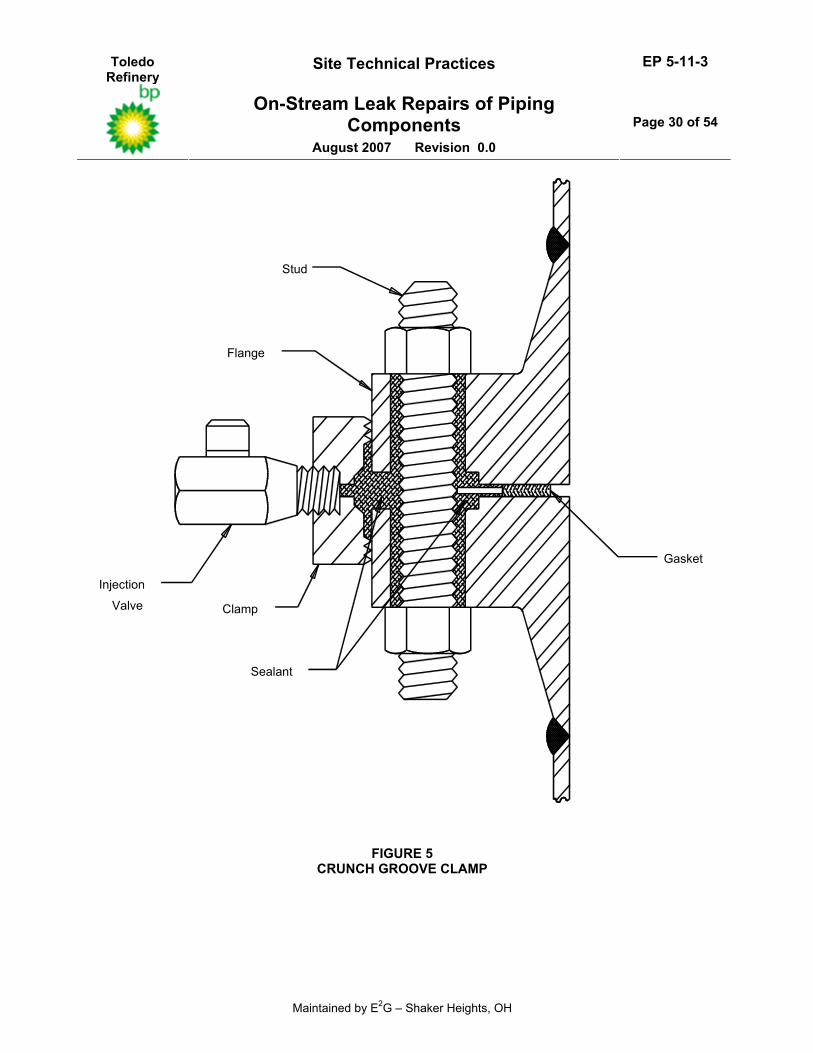
5.5 Crunch Groove Clamp
5.5.1 The crunch groove clamp is a periphery clamp type that utilizes a tooth shaped labyrinth to achieve a metal–to–metal seal on the outside diameter of the flange, see Figure 5.
5.5.2 This clamp can be used for any combination of high pressure, high temperature and severe leaks. However, its use is limited to flanges that have machined surfaces on the flange outside diameter and are aligned with very little mismatch. The crunch groove clamp is normally used only when there is a combination of high temperature, very high pressure (above 2000 psig), and/or severe leakage.
Toledo Refinery
Site Technical Practices EP 5-11-3
On-Stream Leak Repairs of Piping Components
August 2007 Revision 0.0
Page 8 of 54
Maintained by E2G – Shaker Heights, OH
5.5.3 Like the tongue clamp, the crunch teeth are 0.110 inches deep and are not designed for an interference fit. The crunch teeth should contact the flange outside diameter at the same time as the clamp ring split–lines make contact.
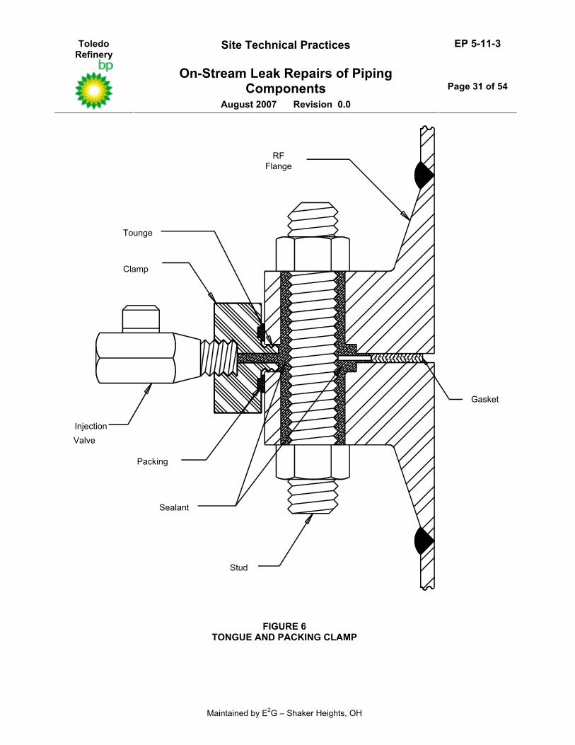
5.6 Tongue and Packing Clamp
5.6.1 The insert and periphery clamp types can be combined to achieve designs that have primary and secondary seals, see Figure 6. In the tongue and packing clamp, the tongue forms the primary seal in the flange gap and the packing is used to form a secondary seal on the flange outside diameter.
5.6.2 This clamp has similar service restrictions as those cited for the tongue clamp.
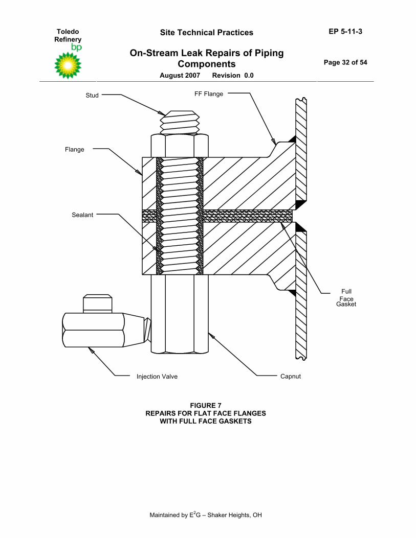
5.7 Clamps for Flat Face Flanges
5.7.1 Flat Face Flanges with full-face gaskets cannot be sealed using only a clamp at the flange outside diameter, see Figure 7. If a flange clamp were installed on this flange to seal a leak at the gasketed joint the leak path would move to a bolt hole. The resulting leak at a bolt hole could not be sealed by injection of additional sealant into the clamp because the sealant would be unable to travel from the clamp to the bolt hole because of the full face gasket.
5.7.2 To achieve a leak seal for a full-face gasket, injection nuts or rings are installed and sealant is injected into the bolt holes. During this process, if seepage of sealant is noted at the flange outside diameter, a tensioned cable or clamp can then be installed around the flange to allow bridging of the sealant.
5.8 Wire Wrapping
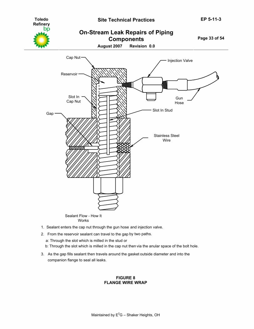
5.8.1 In the wire wrap procedure, stainless steel wire is wrapped in the flange gap until the gap is filled with wrapping wire, see Figure 8. Sealant is then injected through injection nuts that are installed prior to the wire wrap, see paragraph 5.8.3. Sealant travels through the injection nut, through the stud hole and into the flange gap area. The wire retains the sealant and allows the entire gap as well as all stud holes to be filled with sealant. This seals off the leak completely when the sealant is compressed.
5.8.2 (*)The following service and geometry limitations shall be used for the wire wrap procedure unless the LRC can demonstrate suitable experience with other criteria. This experience shall be presented to the Owner’s Engineer for approval prior to the commencement of the repair procedure. • 0.375 inch maximum gap between flanges • 650 psig service pressure • NPS 30 inch maximum flange diameters • ANSI Flanges (4 bolt minimum)
5.8.3 Prior to installation of the wire wrap, bolt tension is checked to verify uniform tension on all bolts. Then a nut is removed from one of the bolts and replaced with an injection nut. The stud may be replaced with an injection stud to provide additional sealant travel if the gap between the stud and the stud bore is so restrictive as to limit sealant travel through the nut only. The injection nut is tightened to the required bolt tension, and another nut is then replaced with an injection nut. This procedure is repeated until injection nuts have been installed (evenly distributed) on at least half of the flange bolts.
5.8.4 The use of wire wrapping to effect on–stream repair of flange leaks has been widely used for many years and is proven to be an effective repair method for flange leaks. It affords the LRC the ability to repair flange leaks immediately with materials that are readily available. It is an inexpensive repair procedure and does not require peening or drilling of the flanges in order to achieve a seal.
Toledo Refinery
Site Technical Practices EP 5-11-3
On-Stream Leak Repairs of Piping Components
August 2007 Revision 0.0
Page 9 of 54
Maintained by E2G – Shaker Heights, OH
5.9 Flange Peening
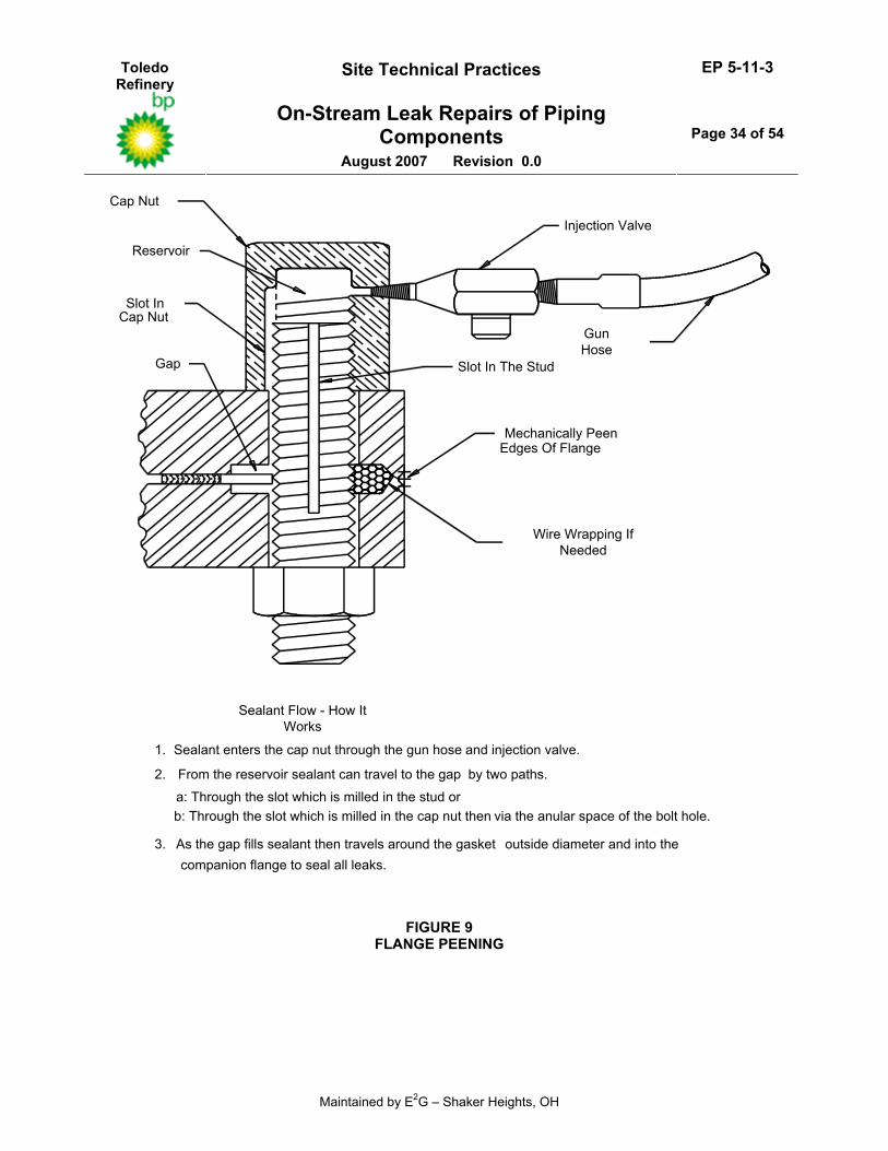
5.9.1 In the peening procedure, the inside edges of the flanges are mechanically peened to create a cavity for the sealant, see Figure 9. Sealant is then injected through injection nuts that are installed prior to the peening operation (see paragraph 5.8.3). Sealant travels through the injection nut, through the stud hole and into the flange gap area. The peening retains the sealant and allows the entire gap as well as all stud holes to be filled with sealant. This seals off the leak completely when the sealant is compressed.
5.9.2 Peening the edges of a flange to create a cavity for sealant is not recommended for most applications. This is because the flange may become distorted to the point where machinery in the field is required to affect bolt–up after the repaired joint is dismantled. Peening may also result in excessive vibration and additional stress on the component being repaired.
5.9.3 Peening is typically limited by the gap between the flange surfaces. The maximum permitted gap should be less than 0.125 inches. If a larger gap is used, an insert wire shall be used to minimize the peening required to affect a seal, see Figure 9.
5.9.4 (*)For carbon steel and low alloy materials, the minimum operating temperature of a flange that can be sealed using the peening technique shall be 120°F, unless otherwise approved by the Owner’s Engineer. This temperature limitation is set to minimize the potential for a brittle fracture during the peening process. Peening shall not be performed on low alloy materials in Hydrogen Service due to the possible loss of toughness resulting from temper embrittlement.
5.10 Flange Banding
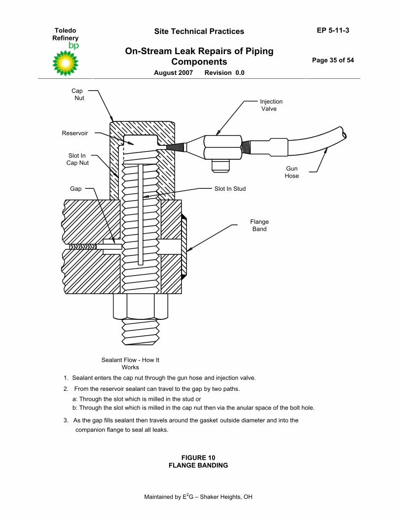
5.10.1 (*)Flange leakage can be sealed by welding a steel band around the perimeters of the flanges and then seal welding around the nuts to prevent further leakage, see Figure 10. Because of the welding involved, this technique is recommended only for limited to ASME B31.3 Category D Services. It should not be used for on–stream repairs of hydrocarbon lines unless the hot work can be safely performed and is approved by the Owner’s Engineer.
5.10.2 Size is not a limitation with this technique since the band can be as thick as necessary to contain the line pressure and any flange circumference can be banded.
5.10.3 The use of carbon steel bands above 800°F is not recommended since the strength and oxidation resistance decrease rapidly above this temperature. However, higher grade materials such as stainless steel can be used for higher temperature applications as long as they are weldable, and differential thermal expansion considerations are evaluated.
5.10.4 While the band should be designed to withstand the internal pressure from the point of view of the circumferential stresses, it is generally impractical to design the band to take the full axial hydraulic pressure loads (assuming the bolts do not exist.) Consequently, if the bolts are subject to deterioration in service due to corrosion, erosion, oxidation or stress corrosion cracking, this technique should not be used.
5.11 Causes of Flange Leakage
5.11.1 Understanding the causes of flange leakage is a major factor in evaluating effective repair techniques. Some of the most common causes of leakage are described in this Section.
Toledo Refinery
Site Technical Practices EP 5-11-3
On-Stream Leak Repairs of Piping Components
August 2007 Revision 0.0
Page 10 of 54
Maintained by E2G – Shaker Heights, OH
5.11.2 Low Bolt Tension - In most flanged joints, tension in the bolts is used to resist the internal pressure and provide adequate seating loads for the gasket. If the bolts are not adequately tensioned, leakage will result. In many cases, only some of the bolts will have inadequate tension and consequently the flange will only leak in areas close to these bolts. Leakage can often cause changes in flange temperature around the leak that can lead to further leakage by causing increased flange bending and further loosening of the bolts. Where non–metallic gaskets are used, low bolt tension can sometimes result in blowing out sections of the gasket because the loss of the gasket seating force (which accompanies bolt loosening) reduces the restraining friction force between the gasket and the flange faces.
5.11.3 High Stud Tension - Excessive stud tension can cause flange leakage by either damaging the gasket or the flange itself. An initial bolt tension equivalent to a stress of 40,000 to 50,000 psi is normally required to prevent flange leakage. Higher bolt tension can lead to excessive loading of certain types of gaskets to a point where they no longer have sufficient elasticity to prevent leakage even under minor changes of temperature or pressure. In addition, high bolt tension can also overload the flange itself and cause excessive rotation. Large flange rotations can redistribute the flange loading across the gasket width and reduce the seating area, giving a shorter leakage path and possibly crushing the outer edge of the gasket. Hot bolting tightening of already over–tensioned bolts can increase leakage by further damaging the gasket and flanges and consequently is not recommended.
5.11.4 Damage to Flange Faces and Gaskets - Defects to flange faces and gaskets such as scratches and gouges can create leakage paths and allow fluid to escape. In some cases, erosion or corrosion of the gasket and/or the flange face can occur which will eventually lead to the formation of a leakage path. For example, external steam rings have caused erosion/corrosion of solid soft iron gaskets that subsequently led to major leakage. Many steam leaks are initiated by low bolt tension, and as soon as a leakage path is formed, erosion of the flange face and gasket will occur and result in greater leakage. In the event of damage to flange faces and gaskets, hot bolt tightening is unlikely to prevent leakage and another technique should be employed. However, a careful evaluation of the possible consequences of not fully repairing a leak where erosion/corrosion could occur is required.
5.11.5 Varying Operating Conditions - Alterations in operating temperature and pressure cause changes to the gasket seating load and bolt tension. These changes can sometimes lead to flange leakage. Rapid temperature changes commonly produce flange leakage as they can significantly alter the bolt load and gasket seating load. However, very often the leakage stops when the flange and bolts reach steady state conditions. In some units operating procedures have been altered to reduce the rate of temperature changes to flanged joints and thereby solve leakage problems. Reducing temperature changes to a rate of less than 100°F/hr. should prevent most cases of leakage due to temperature transients. However, in the long term, severe cyclic temperatures will lead to leakage since the joints may be over–stressed and a loss of elasticity eventually leads to leakage. Tightening of the bolting on–stream is frequently successful in preventing flange leakage due to long term temperature cycling. Care should be taken when using other techniques to prevent leakage to ensure that any leakage that occurs as a result of an operating condition change does not go undetected.
5.11.6 Improper Flange Alignment - Improper alignment, especially lack of flange face parallelism, can cause uneven bolt loading and gasket compression, local crushing and subsequent leakage. Proper centerline alignment of flanges is also important to assure even compression of the gasket. Flange alignment criteria are cited in EP 5-5-3.
Toledo Refinery
Site Technical Practices EP 5-11-3
On-Stream Leak Repairs of Piping Components
August 2007 Revision 0.0
Page 11 of 54
Maintained by E2G – Shaker Heights, OH
5.11.7 Improper Gasket Centering - A gasket that is installed so that its centerline does not coincide with the flange centerline will be unevenly compressed with the possibility of subsequent leakage. Spiral wound and double jacketed asbestos gaskets are provided with a centering ring or gasket extension to the inside diameter of the bolt circle to facilitate gasket centering. Even so, the gasket should be centered with respect to the bolt circle. Sheet gaskets should be cut so that the outside diameter extends to the inside diameter of the bolts for centering considerations.
5.11.8 Excessive Bending Moments in Piping Systems - This can occur because of improper piping flexibility design, or by excessive application of force to attain flange alignment. Improper location of temporary or permanent restraints or supports can also cause high flange bending moments. A method which can be used to evaluate the potential for flange leakage due to an applied bending moment is given the ASME Code, Section III. In this method, a piping stress analysis is utilized to determine the bolt and flange stresses acting on the flanged joint.
5.11.9 Improper Bolting and Gasket Size or Material - Since the bolting and gasket materials are major factors in a flange joint design, improper selection can have a major impact on joint reliability. Requirements for bolting and gasket selection are covered in EP 5-2-2.
5.11.10 Improper Flange Facing - EP 5-2-2 stipulates that raised face flanges shall have a finish meeting the requirements of ASME B16.5. This finish has 30 to 55 grooves per inch, cut spirally or concentrically with a round nosed tool. In addition, a 125-250 micro inch roughness is also a requirement in EP 5-2-2 (as compared to a 125-500 roughness permitted by ASME B16.5). This surface roughness is stipulated in EP 5-2-2 because it is the roughness recommended by most spiral wound gasket manufacturers. For ring type joint flanges (RTJ), the grooves must be cut to very close tolerances and finished to 63 RMS. In older flanges, RTJ gaskets often must be lapped into the groove to ensure a tight fit and leak tightness.
6.0 REPAIRS USING ENCLOSURES (BOXES)
6.1 Overview
6.1.1 Enclosures are used to fully enclose (box) a leaking or substantially thinned component to affect a on–stream repair. When the enclosure is installed, a sealant cavity is created surrounding the leak. In general, the cavity then has to be injected with sealant to seal the leak (expansion joints are an exception).
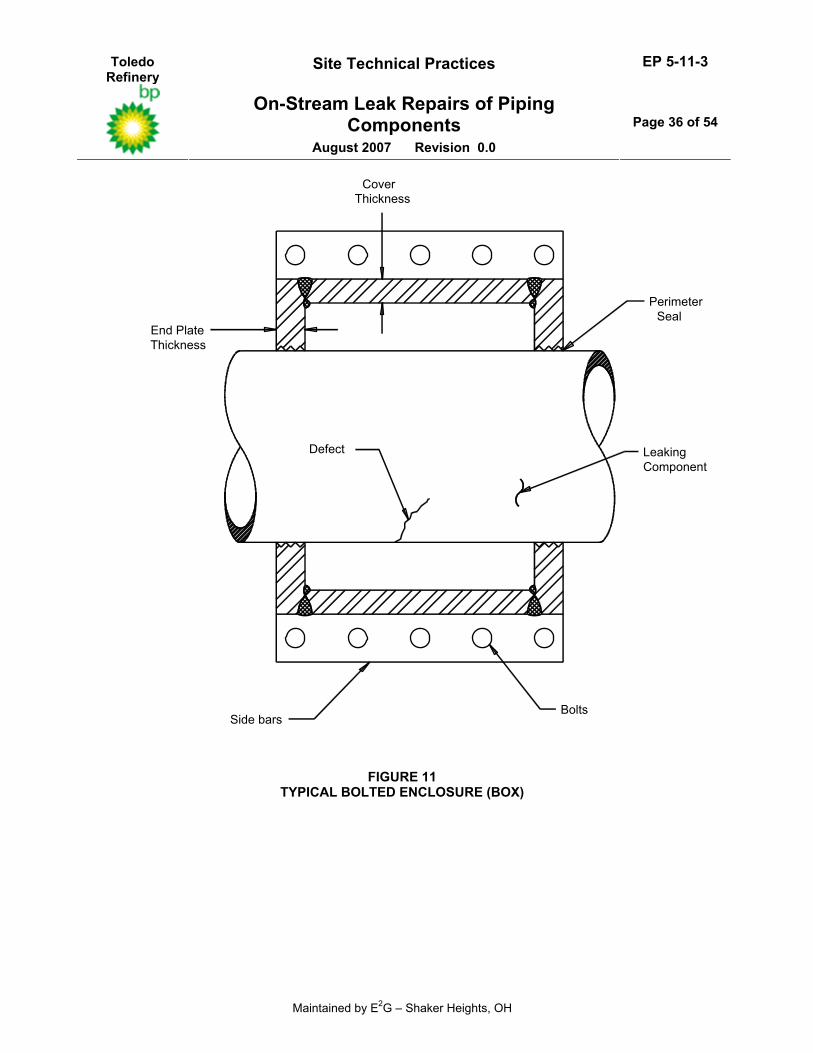
6.1.2 Enclosures are available in many forms (depending on the leaking component) as prefabricated standard stock items that can be installed on the leaking component by bolting. The end plates on an enclosure create the sealant cavity and are the feature that distinguishes enclosures from flange clamps. The nomenclature used for bolted enclosures is depicted in Figure 11.
6.1.3 (*)Enclosures can also be made by fabricating a custom box that is designed to fit around the leaking component configuration. Custom designed boxes can either be installed by bolting or welding directly to the leaking component. Installation of a box by welding directly to the leaking component is limited to ASME B31.3 Category D Services. It should not be used for on–stream repairs of hydrocarbon lines unless the hot work can be safely performed and is approved by the Owner’s Engineer.
6.2 Pipe and Pipe Fitting Enclosures
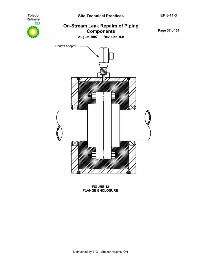
6.2.1 A full flange enclosure is shown in Figure 12. Note that with this type enclosure, a strongback is provided in the event of failure of the bolts by means of the sealant and end plates.
Toledo Refinery
Site Technical Practices EP 5-11-3
On-Stream Leak Repairs of Piping Components
August 2007 Revision 0.0
Page 12 of 54
Maintained by E2G – Shaker Heights, OH
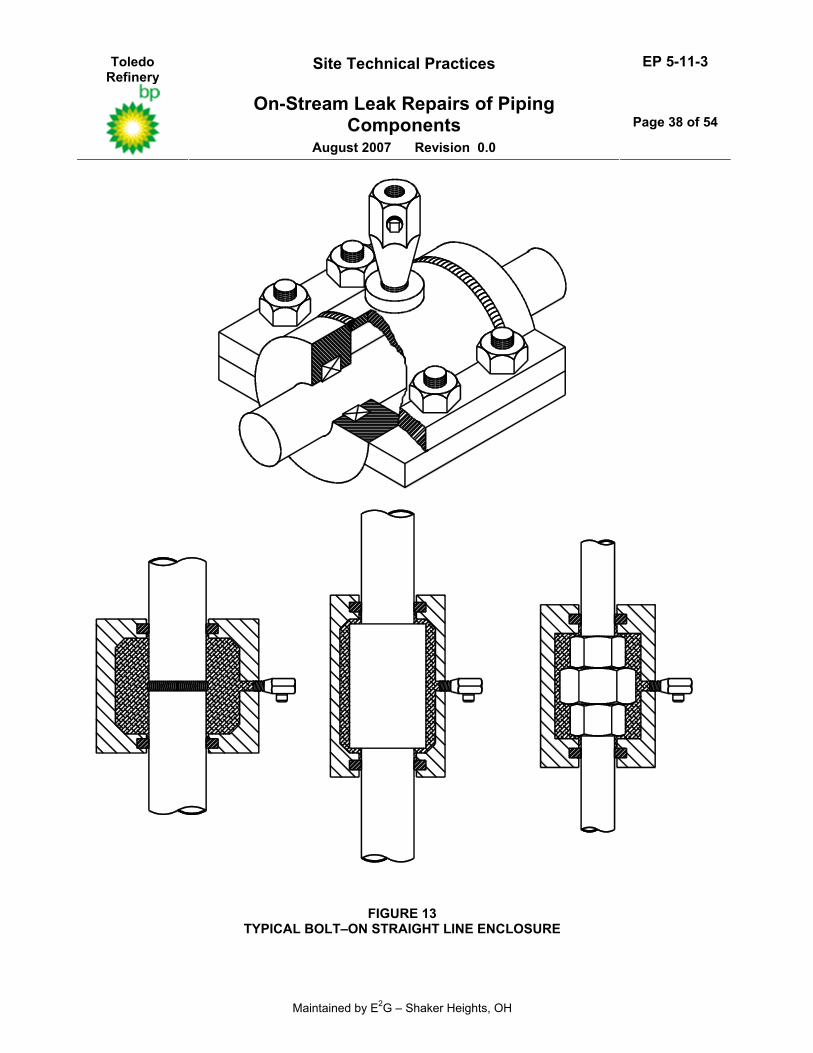
6.2.2 A typical straight line enclosure that may be used to enclose a weld joint or a leak through the wall of the pipe is shown in Figure 13. In the enclosure shown, packing is used in this enclosure to seal against the pipe. The packing that is installed in the end plates is compressed against the pipe when the enclosure halves are bolted together. The enclosure is designed for clearance at the closure point and does not make metal to metal contact with the pipe.
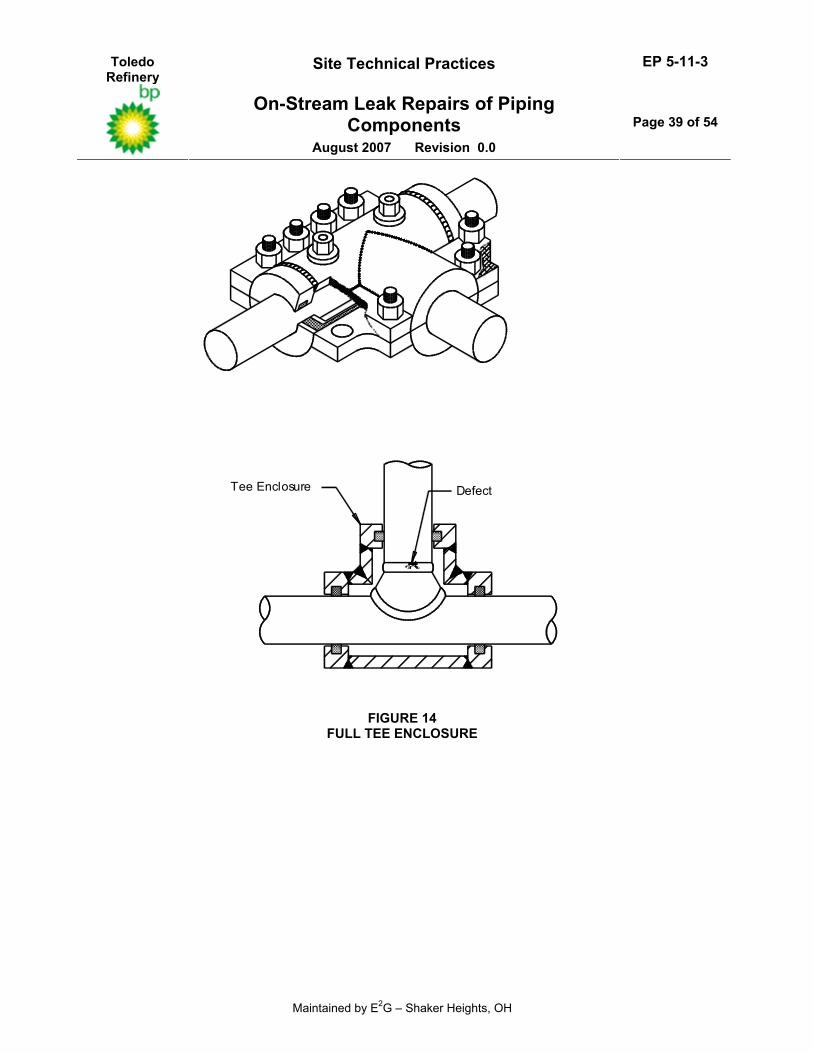
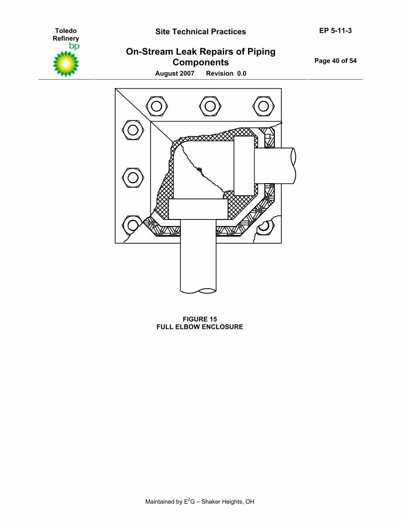
6.2.3 A full tee enclosure is shown in Figure 14. The injection ports and the bolting which holds the enclosure halves together are also shown in this figure. Enclosures are also commonly used to totally enclose 45° or 90° elbows. The one shown in Figure 15 is a single miter 90° enclosure. For enclosing 90° long radius weld ells a double miter enclosure is used.
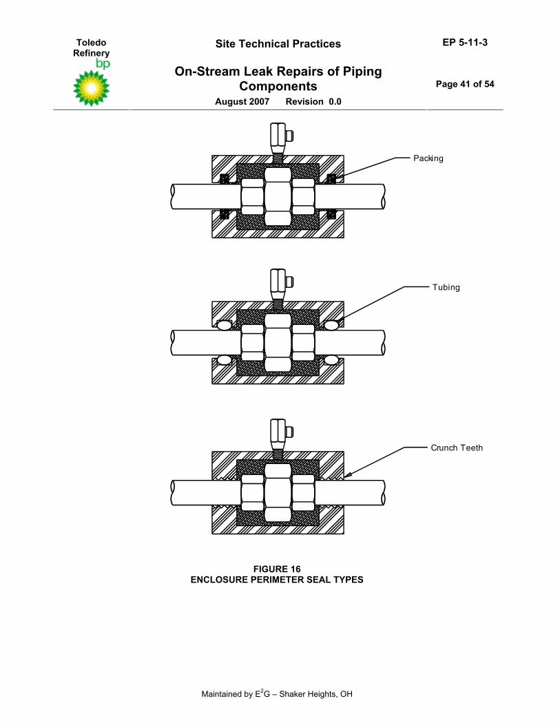
6.2.4 Packing for an enclosure seal is used below 300 psig design pressures to allow the sealant to bridge over the leak and fill the void cavity. When the service pressure is above 300 psig, tubing and crunch teeth seals are used. These three seal types are shown in Figure 16.
6.2.4.1 (*)Copper tubing may be used as a standard for design temperatures up to a maximum of 450°F. Stainless steel tubing shall be used for design temperatures above 450°F and for all clamps installed on services which are categorized to be in AES, unless otherwise specified by the Owner’s Engineer.
6.2.4.2 Crunch teeth are used to seal severe, high pressure leaks. It is important to note that crunch teeth are not designed to bite into the pipe during installation. The crunch teeth bore is made to the same dimension as the pipe diameter and no interference is intended.
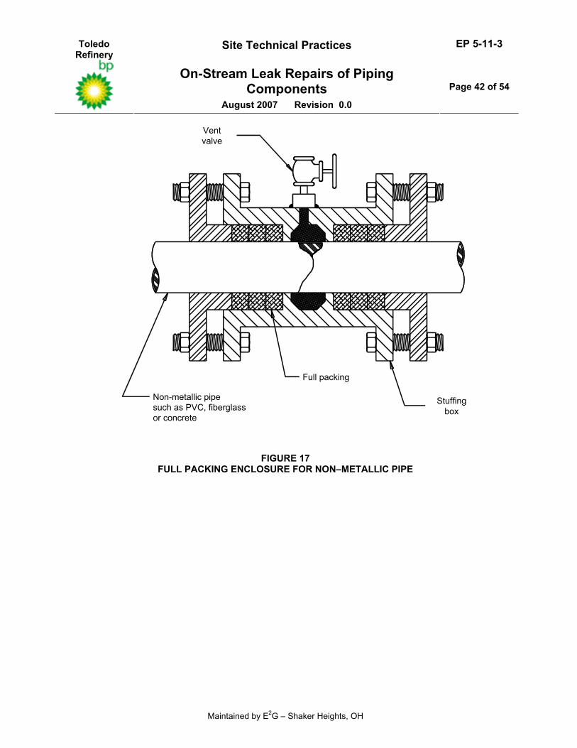
6.2.5 A full packing or packing gland type enclosure is shown in Figure 17. This type of enclosure is used to repair leaks in non–metallic pipe made from PVC, fiberglass, clay, concrete or glass. Since only the packing material is in contact with the pipe, the force against the pipe is uniformly distributed and would not cause breakage of the fragile pipe.
6.2.6 Pipe and pipe fitting enclosures can typically be reused if the tubing and packing are changed each time.
6.3 Valve Enclosures
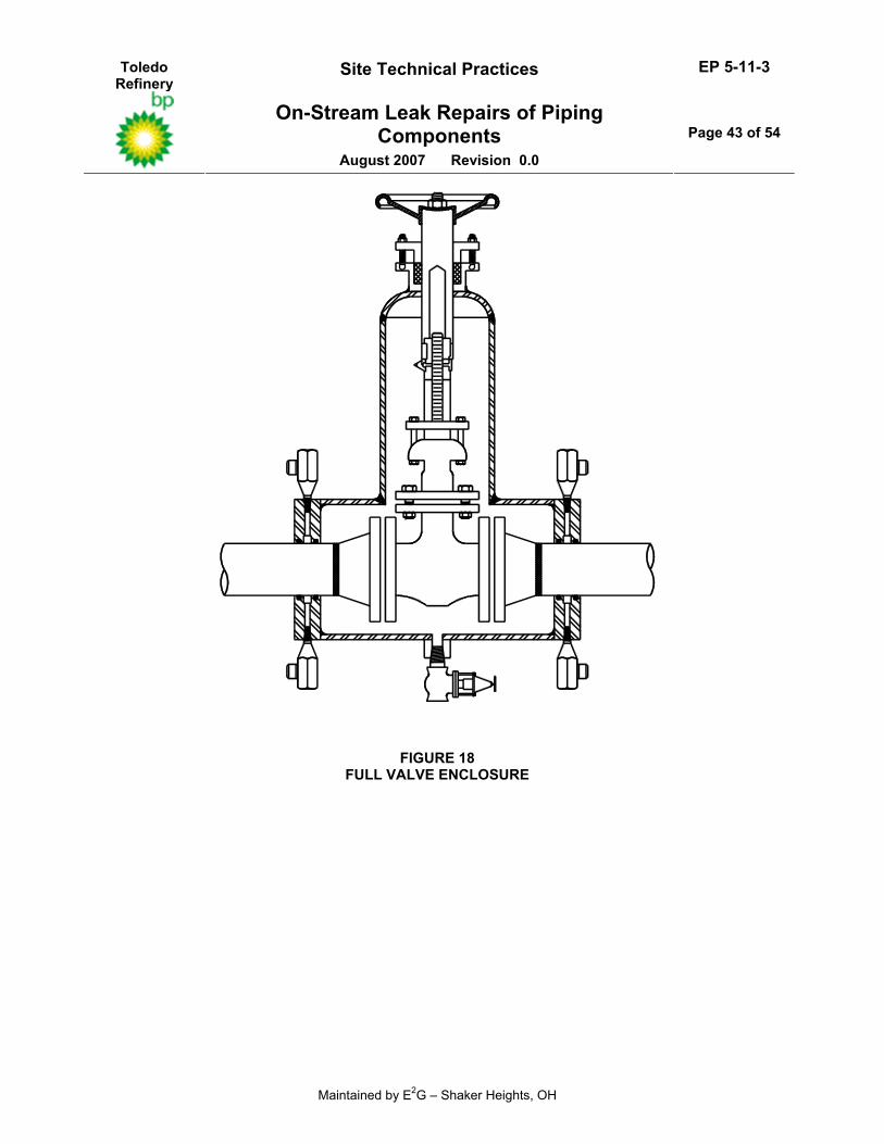
6.3.1 A perimeter seal type enclosure can be used when enclosing valves, see Figure 18. When the perimeter seal design is used, it must be designed recognizing that the void cavity in the enclosure will be pressurized with line pressure and filled with the service fluid. Therefore, materials for the enclosure must be compatible with the fluid service.
6.3.2 Considerations should also include whether the service is susceptible to freezing. Since the enclosure’s void area will fully contain the fluid in a pressure boundary outside its normal flow path, there will be a ”dead” area that could freeze and rupture during cold weather.
6.4 Expansion Joint Enclosures
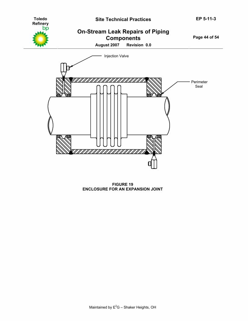
6.4.1 Expansion joint enclosures must utilize a perimeter seal type because the enclosure cavity must not be filled with sealant. If it were, sealant pressure in the cavity would collapse the metal bellows and flow through the line would be restricted.
6.4.2 An enclosure for expansion that utilizes a perimeter seal is shown in Figure 19. In this design, a double row of packing is used with a sealant groove between the two rows of packing. This type enclosure will effectively seal the leak, but any significant movement of the pipe at the closure point will break the seal and resealing requires re–injection of sealant.
Toledo Refinery
Site Technical Practices EP 5-11-3
On-Stream Leak Repairs of Piping Components
August 2007 Revision 0.0
Page 13 of 54
Maintained by E2G – Shaker Heights, OH
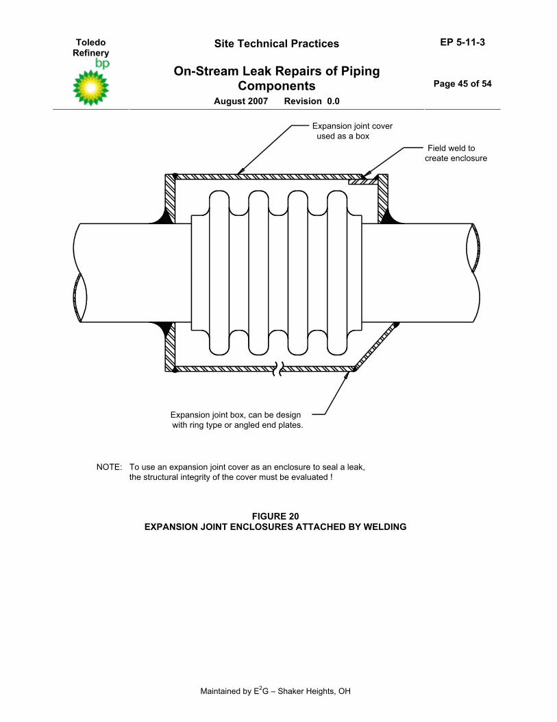
6.4.3 If welding is permitted, an enclosure or box can be prefabricated and fitted around the leaking expansion joint and the perimeter seal can be made by welding, see Figure 20. Alternatively, the expansion joint cover can be utilized as the box if it has ample strength. When this type of enclosure is used, it should be installed while the expansion joint is in the operating condition. This is because the enclosure will restrict all movement at the expansion joint. Extreme care should be exercised when removing the enclosure during a shut–down because energy stored in the piping system will be released when the enclosure is removed.
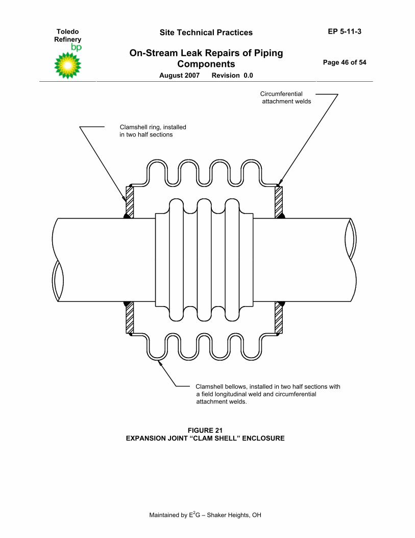
6.4.4 As an alternative to an enclosure or box with a perimeter seal, “clamshell” repairs have also been used to repair expansion joints on–stream, see Figure 21.
6.4.4.1 A typical clamshell is a formed bellows element that is cut into two or more sections for field installation. Clamshells are formed to a diameter large enough to completely enclose the leaking bellows expansion joint.
6.4.4.2 The clamshell installation requires a metal surface to which the bellows element must be attached. The attachment surface is usually a set of rings that are installed in segments around the pipe and then butt or fillet welded to the pipe surface.
6.4.4.3 The clamshell sections are installed around the leaking bellows, tack welded together, the bellows assembly is attached to the rings, and then the complete assembly is welded in place.
6.4.4.4 The clamshell is the best alternative for enclosing an expansion joint because after installation, movement of the expansion joint is still possible.
6.4.5 Expansion joints designed in accordance with EP 5-4-1 have external covers which can be seal welded in the event of a leak. Seal welding of this cover will result in restriction of expansion joint movement. Type 3 “piggy back” expansion joints per EP 5-4-1 are designed with a secondary seal bellows. In the event of a leak, this bellows is jacked into place and seal welded. The advantage of this design is that the enclosure used to seal the leak is made using an expansion joint; therefore, bellows movement is permitted after installation of the enclosure.
6.4.6 If the design of the expansion joint enclosure or box requires removal of tie rods, hinge joints or other external hardware which is used to provide support for the axial pressure thrust load, the enclosure shall be designed to fully support this load.
7.0 REPAIRS TO VALVES
7.1 Valve Packing Leaks
7.1.1 As a first attempt to eliminate valve packing leaks, adjust the packing gland as follows: re–torque gland bolts to their recommended value, add a lubricant to the packing material around the stem (for example, CLIMAX, DEMNUM, etc.) and stroke the valve five times re–torquing the gland bolts after each stroke. Be sure the lubricant is compatible with the service media and temperature.
7.1.2 Valve packing and seat leaks may be sealed on–stream using a sealant injection method similar to the one used for flanges.
7.1.3 Leaking valve packing glands shall be repacked using injected packing material rather than a sealant. The valve packing material shall not cure or otherwise solidify, and shall have compliance throughout its useful life.
Toledo Refinery
Site Technical Practices EP 5-11-3
On-Stream Leak Repairs of Piping Components
August 2007 Revision 0.0
Page 14 of 54
Maintained by E2G – Shaker Heights, OH
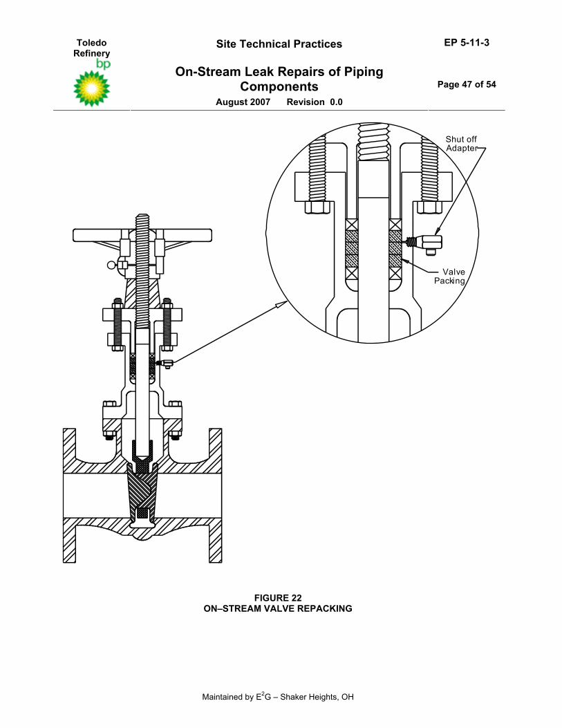
7.1.4 A valve packing leak may be sealed by injecting packing material into the existing valve stuffing box. The means for injection of the packing material is provided by drilling a small hole into the packing area. This hole is tapped and a shutoff adapter is threaded into the tapped hole. The valve stuffing box is then repacked by filling it full of packing material by the injection process, see Figure 22. The valve packing gland should be left in the fully extended position to allow for future adjustment.
7.1.5 The holes drilled for injection of the packing shall be drilled and tapped into the packing box wall exercising care not to drill into the pressurized packing until the injection valve has been threaded into the tapped hole.
7.1.6 If further usage of the injection valve is expected, the injection valve can remain on the packing box of the repacked valve. Otherwise, the injection valves shall be removed after the valve is repacked and the injection hole plugged with an appropriate drill–through safety plug.
7.1.7 The Leak Repair Contractor shall warrant that all valves will remain fully operable after repacking and that steps are taken during the repair procedure to prevent extrusion of valve packing material into the process stream.
7.2 Valve Seat Leaks
7.2.1 Valve seat leaks may also be sealed by drilling and tapping an injection port into the body of the valve. Seat leaks are internal rather than external leaks but can adversely affect plant operations. Occasionally, seat leakage may contribute to package gland leakage. The following procedures for valve seat leakage repair shall be used only to prolong valve operation until the next maintenance opportunity. At that time, the valve must either be repaired and the injection ports plugged, or replaced with a new valve.
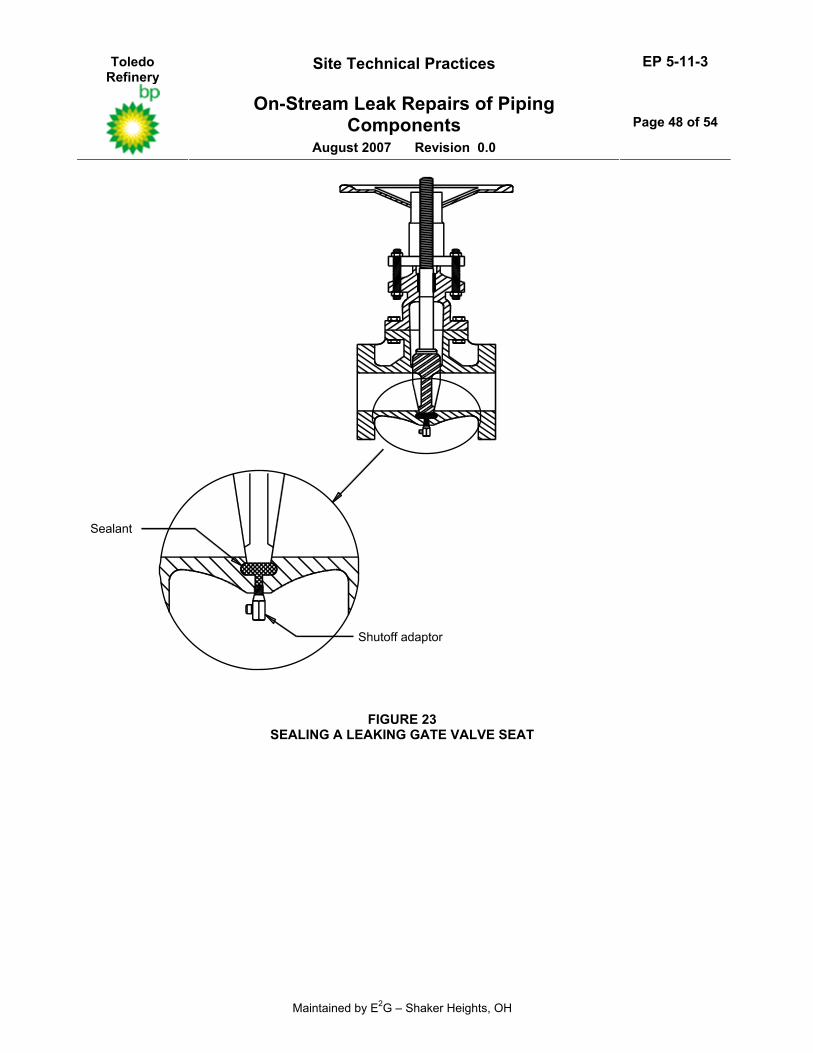
7.2.2 Gate valve seat leaks may be sealed when the leak occurs in the bottom portion of the gate. Injection ports must be installed and sealant, rather than valve packing material, is injected while the valve is in the closed position, see Figure 23.
7.2.3 (*)Ball valve seat leaks are injected with a packing material between the two seals, in the valve body, with the valve in the open position, see Figure 24. The valve is then closed to isolate the process. The drilled hole for the shutoff adapter should be in the center position. The injected material should be the same as the packing material. A sealant that will not adhere to the ball may be used with the approval of the Owner’s Engineer.
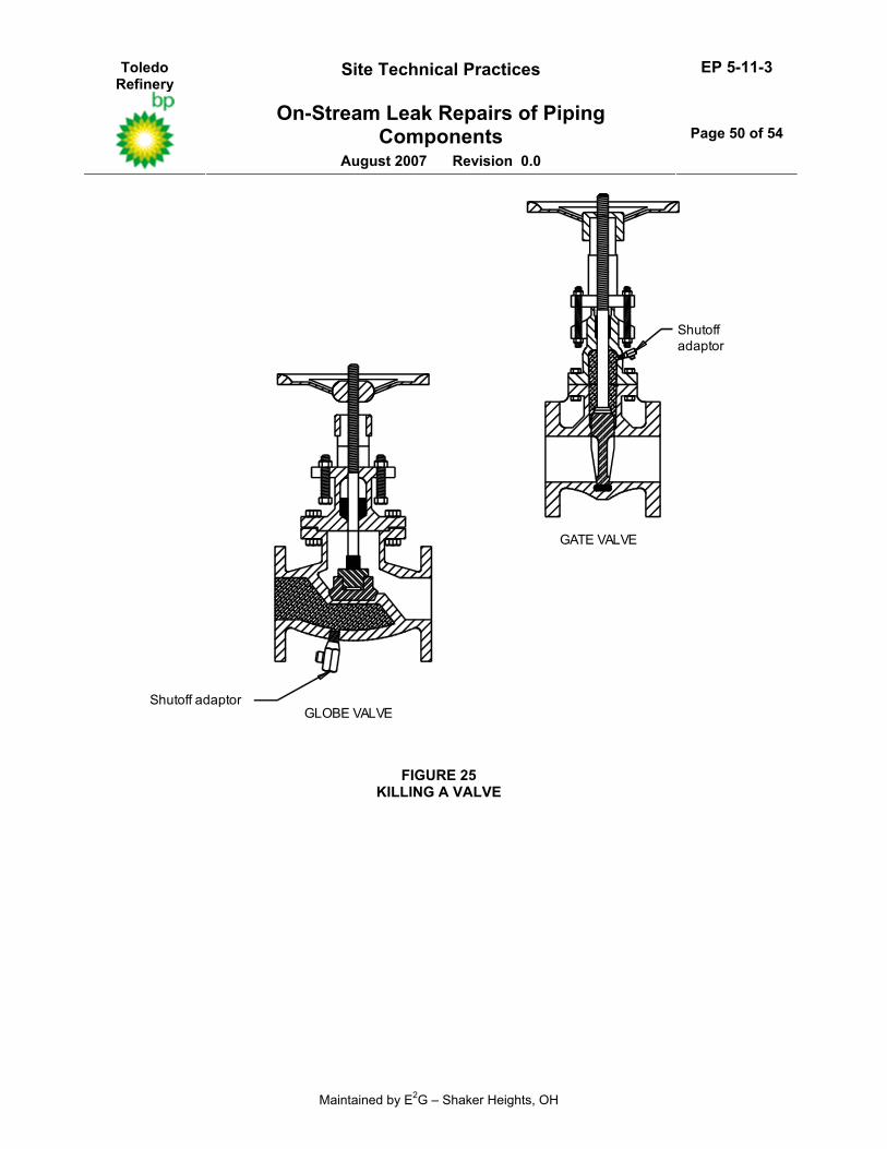
7.2.4 For globe valves, seat leaks can only be sealed by “killing” the valves or making them inoperable. This is accomplished by injecting sealant into the valve inlet to block the flow to the valve seat. Similarly, ball valves may be “killed” or rendered inoperable when sealant is injected into the valve body with the valve in the closed position. Gate valves are killed by injecting a sealant upstream into the valve bonnet area and all around the gate, see Figure 25.
7.3 Pressure Seal Bonnet Leaks
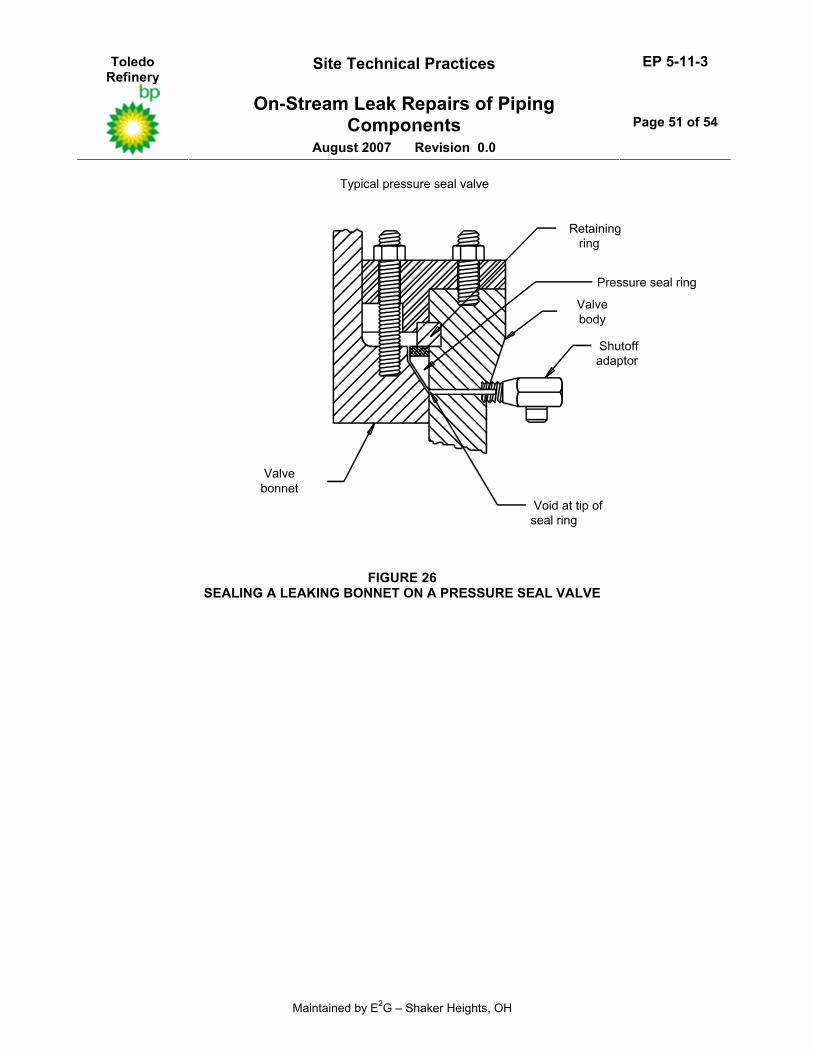
7.3.1 The bonnet seat rings on pressure seal bonnet valves can also be sealed using an injection method, see Figure 26. However, achieving a seal is difficult due to the small space available at the tip of the seal ring into which compound can be injected.
7.3.2 Exact dimensions must be provided by the valve manufacturer to determine the correct drill point for the shutoff adapter. On larger valves, more than one injection point may be required. Once the adapters are in place, a sealant compound is injected around the small gap at the tip of the seal ring.
7.3.3 Some valve designs lend themselves to the success of this technique more than others. Many designs have virtually no gap at the tip of the seal ring and an alternative cavity, such as a thread relief must be injected.
Toledo Refinery
Site Technical Practices EP 5-11-3
On-Stream Leak Repairs of Piping Components
August 2007 Revision 0.0
Page 15 of 54
Maintained by E2G – Shaker Heights, OH
7.3.4 (*)The valve should not be injected in the area of the “knock–out” segmented ring or directly below the bonnet retaining ring without a thorough engineering evaluation and the approval of the Owner’s Engineer.
8.0 TUBE CRIMPING
8.1 Overview
8.1.1 Tube crimping can be used to seal off leaking tubes in reformer fired heaters while in operation. In this method, a mechanically actuated crimp block is placed on the reformer tube inlet and outlet pigtails. The tube is then crimped to choke off flow.
8.1.2 There are two basic methods employed for tube crimping. In the first method, single crimp blocks are used on the inlet and outlet pigtails to achieve a seal. In the second method, dual crimp blocks with an intermediate injection clamp ring are used to achieve a seal. The injection clamp is utilized for injection of a sealant to insure a leak tight seal. The second method is recommended for hydrogen and steam reformer heaters.
8.2 General Requirements
8.2.1 Depending on the material of the pigtail, a minimum metal temperature must be maintained to insure that sufficient ductility exists to crimp the tube without causing cracking. For Inconel 600 pigtails, the minimum recommended temperature is 700°F. For other alloys, the minimum temperature shall be established by considering the material property and the condition of the pigtail.
8.2.2 Adequate cooling must be provided to insure that relaxation of the crimp block studs does not occur. Relaxation will result in leakage at the crimp location.
8.2.3 After the tube has been crimped, the loss of fluid flow will result in an increase in the tube metal temperature. Therefore, tube supports may have to be adjusted to accommodate the associated additional thermal expansion of the tube.
8.2.4 If the tube is being isolated because of catalyst blockage (as opposed to an external leak), the pigtail should be hot tapped after the crimping operation to bleed off any remaining pressure inside the tube. This precaution will help to minimize the risk of a fire inside the heater in the event of a tube rupture due to overheating of the tube material.
9.0 DOCUMENTATION AND RECORD RETENTION
9.1 Requirements For New Leak Repair Devices (LRD)
9.1.1 The following drawings, calculations and material data shall be supplied along with each LRD:
9.1.1.1 A cross–sectioned drawing with all dimensions required for fabrication showing the following: • design pressure and temperature • maximum sealant injection pressure to be used during installation and the volume of sealant • corrosion allowance • materials of construction • weld details • total weight (including estimated weight of sealant) and support structure design if necessary • sealing device identification number • plant identification, unit number and description of clamp location • sealant or packing material • strong-back drawing (including location with respect to clamp)
Toledo Refinery
Site Technical Practices EP 5-11-3
On-Stream Leak Repairs of Piping Components
August 2007 Revision 0.0
Page 16 of 54
Maintained by E2G – Shaker Heights, OH
• field sketch with measured critical dimensions
9.1.1.2 A completed On–Stream Leak Sealing Data Sheet. Any exceptions to the requirements of this Practice must be indicated on the data sheet.
9.1.1.3 All mechanical design calculations required to demonstrate the structural adequacy and compliance to this Practice, see section 12.0.
9.1.1.4 Welding Procedure Specifications (WPS) and Referenced Procedure Qualification Records (PQR) for all fabricated LRDs.
9.1.1.5 Certified Material Test Reports or Certificates of Compliance.
9.1.1.6 Welding inspection records.
9.1.2 One copy of all drawings, calculations and material data shall be submitted and delivered to the Owner along with the LRD.
9.1.3 (*)All comments and unresolved issues cited by the Owner’s Engineer, if any, shall be resolved by the Leak Repair Contractor
9.2 Records Retention
9.2.1 All documentation including the information in paragraph 9.1.1 shall be submitted to the Owner’s Engineer for review and approval. After approval is obtained from the Owner’s Engineer, see paragraph 9.1.3, all documentation shall become part of the permanent equipment records until that time when the LRD is removed from service, and suitable repairs are performed to restore the full integrity of the component.
9.2.2 The LRC shall retain all documentation outlined in paragraph 9.1.1 for a minimum of five years. Copies of these records shall be made available to the Owner on request.
10.0 SAFETY
10.1 Owner responsibilities
10.1.1 All work associated with sealing on–stream leaks shall be performed in accordance with the local refinery Safety Practices and Procedures Manual, and the additional requirements of this Practice.
10.1.2 All work associated with sealing on–stream leaks shall be performed in accordance with the local plant Safety Practices and Procedures Manual, and the additional requirements of this Practice.
10.1.3 For leak sealing involving welding and/or cutting, precautions should be taken for proper grounding during electric welding and for the cutting of pipelines with cathodic protection systems, if the system cannot be disengaged.
10.2.1 The LRC shall be fully responsible for the safety of his employees and shall provide them with appropriate protective clothing, goggles, face shields, hard hats, safety shoes and gloves. The LRC shall furnish additional safety equipment if the nature or condition of the work requires it.
10.2.2 The LRC shall be responsible for ensuring a safe working environment for his employees. Any unsafe conditions shall be immediately brought to the attention of the Owner’s Engineer, and all leak sealing work suspended while the unsafe conditions exist.
10.2.3 The LRC shall obtain the necessary permits from Owner prior to inspecting the leaking component, and prior to the actual installation of the LRD.
Toledo Refinery
Site Technical Practices EP 5-11-3
On-Stream Leak Repairs of Piping Components
August 2007 Revision 0.0
Page 17 of 54
Maintained by E2G – Shaker Heights, OH
10.2.4 The LRC shall describe to the Owner all possible modes of failure of equipment or devices during installation or pumping of sealant, and discuss contingency plans for the safe evacuation of personnel and the containment of unsafe conditions.
11.0 MATERIALS
11.1 Metallic Materials
11.1.1 All materials used for pressure containing parts (including bolting) shall be in accordance with the ASME Code Section VIII, Division 1. Unless otherwise specified by the Owner’s Engineer, CMTR are required for all materials except bolting.
11.1.2 (*)Unless otherwise specified by the Owner’s Engineer, the material of the leak-sealing device shall be made from the same material (based on ASME Code P–number) as that of the leaking component.
11.1.3 Bolting materials shall be in accordance with EP 5-2-2.
11.1.4 Copper and its alloys, (e.g., brass) and aluminum are not permitted in the pressure containing or load bearing parts of any device. However, copper tubing may be used for leak sealing clamps up to a temperature of 450°F for services that are not categorized as an AES.
11.2 Sealants and Packing Materials
11.2.1 (*)Sealants and packing materials shall be selected by the LRC and submitted to the Owner’s Engineer for approval.
11.2.2 (*)Sealants and injectable valve packing materials shall be asbestos free and Material Safety Data Sheets must be submitted to the Owner’s Engineer prior to use.
11.2.3 Sealants and valve packing materials shall not contain corrosive materials that would result in accelerated corrosion of piping and pressure vessel materials.
11.2.4 The possibility of stress corrosion occurring in piping and pressure vessel components is enhanced by using sealants that contain high levels of chlorine, fluorine, sulfur and heavy metals (arsenic, bismuth, lead, tin and zinc). Therefore, the LRC shall provide documentation indicating that the sealants and valve packing materials meet the following standards (Note: Laboratory tests to determine leachable rather than total quantities are not acceptable.). The test results should be based on an analysis by an independent laboratory: • Total Chloride 150 ppm maximum • Total Fluoride 75 ppm maximum • Total Sulfur 150 ppm maximum • Total Arsenic 50 ppm maximum • Total Bismuth 50 ppm maximum • Total Lead 50 ppm maximum • Total Tin 50 ppm maximum • Total Zinc 50 ppm maximum
11.2.5 Below 450°F, rubber based sealant materials may be used. Above this temperature, thermosetting sealants shall be used.
Toledo Refinery
Site Technical Practices EP 5-11-3
On-Stream Leak Repairs of Piping Components
August 2007 Revision 0.0
Page 18 of 54
Maintained by E2G – Shaker Heights, OH
12.0 DESIGN
12.1 General Requirements
12.1.1 All LRDs and enclosures shall be designed in accordance with the ASME B&PV Code, Section VIII, Division 1 (Code). Any configurations not specifically covered by the Code shall be designed using good engineering practices (see paragraph U–2 of the Code).
12.1.1.1 For design of clamp type LRDs, the design calculations shall include the applicable attributes of the design procedures and details outlined in Appendix 24 of the Code.
12.1.1.2 For welded box type enclosures, the design calculations shall include the applicable attributes of the design procedures and details outlined in paragraph UG–34, Appendix 9 and Appendix 13 of the Code.
12.1.1.3 As an alternative to design calculations, the maximum allowable working pressure of an LRD can be established by a proof test. The proof test shall be in accordance with paragraph UG 101 of the ASME Code, Section VIII, Division 1.
12.1.2 The calculations for all proposed designs shall be explicitly detailed and the source of formula and procedures shall clearly be identified. All possible modes of failure of the material and welds shall be checked and shown to be acceptable.
12.1.3 All design calculations shall be signed by the design engineer representing the LRC.
12.1.4 (*)For custom LRDs, the design calculations shall be submitted to the Owner’s Engineer for review and approval prior to the initialization of fabrication. For standard LRDs or stock items, design calculations shall be submitted when requested by the Owner’s Engineer.
12.1.5 (*)The design conditions and corrosion allowance for the LRD shall be specified by the Owner’s Engineer on the On–Stream Leak Sealing Data Sheet.
12.1.5.1 For clamps and bands around flanges, the clamp or band shall be designed for the maximum permissible flange pressure rating or the maximum sealant injection pressure, whichever is greater. For other LRDs, the design pressure shall be the same as the leaking component, or the maximum sealant injection pressure, whichever is greater.
12.1.5.2 The design temperature shall be equal to the design temperature of the leaking component.
12.1.5.3 (*)A minimum corrosion allowance of 1/8 inch shall be used unless otherwise specified on the data sheet.
12.1.6 If slotted bolts are used to facilitate injection of sealant, the slot shall not decrease the stud strength by more than 10%, and all design calculations shall reflect this decrease. The decrease in strength may be computed based on the reduction in bolt area, or may be established by testing.
12.1.7 (*)In an effort to prevent or minimize the introduction of sealant into the process stream (mainlining), the amount of sealant needed shall be calculated and indicated on the drawing. When feasible the leak in the component shall be covered or sealed before the LRD is installed to prevent seepage of sealant into the process stream, see paragraph 15.3. The amount of sealant in excess of required calculated volume shall not be injected without prior approval by the Owner’s Engineer.
12.1.8 (*)The estimated total weight of the LRD, full of sealant, shall be shown on the drawing. The Owner’s Engineer shall determine that the device can be supported by the leaking component; otherwise, suitable supports shall be designed and installed by the LRC.
Toledo Refinery
Site Technical Practices EP 5-11-3
On-Stream Leak Repairs of Piping Components
August 2007 Revision 0.0
Page 19 of 54
Maintained by E2G – Shaker Heights, OH
12.1.9 The maximum sealant injection pressures shall be determined by calculation or based on testing to assure that damage to piping valves, fittings and bolts will not occur during the repair process. In addition, the maximum sealant injection pressure that can be used without effecting the bolt stress shall be calculated on shown the design drawings, see Section 9.1.
12.1.10 The injection nuts used in all on–stream repairs shall be designed to have equal or greater strength than the hex nut that they replace.
12.2 Requirements For Strongbacks
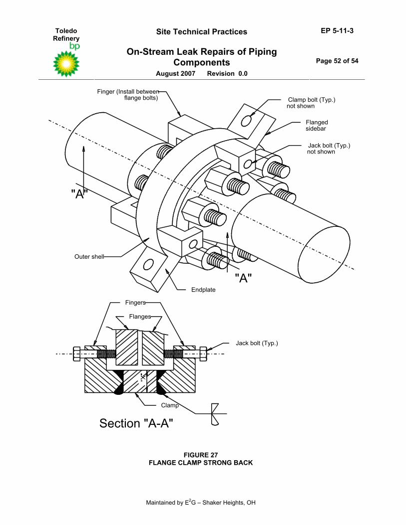
12.2.1 The design of all leak sealing or dissipating devices shall include provisions to support the axial thrust force due to pressure if the component being repaired is (or may become) insufficient to support this force. If the integrity of the component cannot be verified, the LRC shall include in the design package an adequate strongback system that includes provisions to support the unbalanced hydraulic force in the event of a component failure.
12.2.2 The strongback system (screws, crunch teeth, pipe clamp, welded enclosure, etc.) shall be shown to be adequate for the unbalanced hydraulic load. Such devices shall be designed to minimum stresses imposed on piping components. The effect of clamping (crushing) forces on the component also shall be considered. A strongback design is shown in Figure 27.
12.2.3 Strongbacks shall be included on all LRD designs that are to be installed on equipment which is categorized to be in AES, see EP 10-2-1.
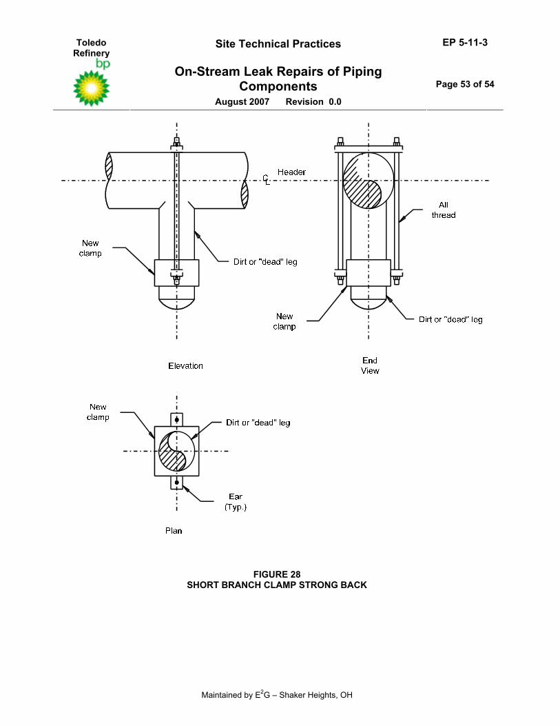
12.2.4 All LRDs that traverse unequal diameters or that are applied to piping components that do not lie in the same straight line (such as elbows) shall be designed to restrain the resulting unbalanced hydraulic loads. Details for a strongback used on a short branch connection are shown in Figure 28. The design of all strongbacks for LRDs closing on different diameters shall assume a sealant cavity pressure no less than 1000 psig or actual design service pressure whichever is larger.
12.3 Requirements For Wire Wrap Designs
12.3.1 (*)Unless otherwise specified by the Owner’s Engineer, stainless steel wire shall be used to seal flange leaks. If less than six turns of wire are used, a backup strap or cable is required to insure blow–out integrity.
12.3.2 The hoop stress developed in the wire shall be calculated and shown to be strong enough to hold the required service pressure. The allowable stress for wire shall be taken as the minimum of one–quarter of the specified minimum tensile strength at ambient and design temperature.
13.0 FABRICATION
13.1 General Requirements
13.1.1 All fabrication shall be in accordance with the ASME Code Section VIII, Division 1 and the additional requirements of this Practice.
13.1.2 LRDs shall be fabricated and welded only in Owner approved fabrication shops; subcontracting to non–approved shops is not permitted.
13.2 Welding
13.2.1 All welding shall be in accordance with EP 5-5-2 or EP 7-1-5, as applicable.
13.2.2 All strength welds shall, preferably, be full penetration welds. If fillet welds are used, their strength shall be calculated for all modes of failure. If fillet welds are used, a joint efficiency no greater than specified in Table UW–12 shall be used. Seal welds may be fillet welds.
Toledo Refinery
Site Technical Practices EP 5-11-3
On-Stream Leak Repairs of Piping Components
August 2007 Revision 0.0
Page 20 of 54
Maintained by E2G – Shaker Heights, OH
13.2.3 All flange to body welds on fabricated LRDs shall be made using a full penetration double sided groove joint.
13.2.4 All double welded groove and corner joints shall be backgouged to a clean metal surface and inspected before completion of the second side of the weld, see paragraph 14.2.2.
13.2.5 Additional requirements for attachment welds that are used to connect the LRD to the leaking component while the component is on–stream are covered in EP 5-7-1. In general, the same requirements for welding to on–stream equipment should be in accordance with those used for hot taps.
13.3 Heat Treatment
13.3.1 (*)Carbon and low alloy steel LRDs shall be post–weld head treated (PWHT) when required by the ASME Code, the AES criteria in EP 10-2-1, or when specified by the Owner’s Engineer.
13.3.2 PWHT shall be in accordance with EP 7-1-5 or EP 5-5-2, as applicable.
13.3.3 (*)PWHT for LRDs installed by welding on low–alloy materials will be stipulated by the Owner’s Engineer. Generally, a butter layer is recommended on low–alloy materials prior to installation of the LRD. The LRD can then be welded to the butter layer without subsequent PWHT.
14.0 INSPECTION
14.1 General Requirements
14.1.1 Magnetic particle examination (MT) and acceptance criteria shall be per the ASME Code, Section VIII, Division 1, Appendix 6.
14.1.2 Liquid penetrant examination (PT) and acceptance criteria shall be per the ASME Code, Section VIII, Division 1, Appendix 8.
14.2 Inspection Of New Leak Repair Devices (LRDs)
14.2.1 All pressure containing welds on LRDs shall be inspected using the MT or PT examination method.
14.2.2 The backgouged clean metal surface of all double sided and corner welds shall be inspected using the MT or PT examination method before completion of the second side of the weld.
14.2.3 Material hardness requirements for components categorized to be in AES are stipulated in EP 10-2-3
14.2.4 Positive Material Identification (PMI) shall be in accordance with EP 15–4–1.
14.2.5 Inspection requirements for welds which are used to attach the LRD to the leaking component shall be as follows:
14.2.5.1 For metal temperatures less than or equal 300°F - Visually inspect the root pass and perform magnetic particle (dry powder technique) or liquid penetrant examination of the final pass.
14.2.5.2 For metal temperatures greater than 300°F - visually inspect each weld pass.
14.3 Inspection Prior To Installation Of A Leak Repair Device (LRD)
14.3.1 For bolted LRDs, visual inspection of the surface area that will be covered by the device is required. The surface that will be used to create the seal with the LRD shall be free of cracks, excessive pitting, rust, scale or insulation residue.
14.3.2 For LRDs that are attached to the leaking component by welding, all inspection requirements stipulated for hot taps shall be utilized including the minimum thickness requirements, see EP 5-7-1.
Toledo Refinery
Site Technical Practices EP 5-11-3
On-Stream Leak Repairs of Piping Components
August 2007 Revision 0.0
Page 21 of 54
Maintained by E2G – Shaker Heights, OH
14.3.3 If a crimp clamp is to be used for an LRD or strongback on a piping system, the thickness in the area where the clamp is installed shall be determined to insure structural integrity during the crimping process. The following thickness limitations shall be followed unless calculations or experience are submitted by the LRC to support alternative values.
• For NPS 2 inches and smaller - 0.10 inches • For NPS 3 inches and larger - 0.15 inches
15.0 INSTALLATION OF ON–STREAM LEAK SEALING DEVICES
15.1 Owner responsibilities
15.1.1 (*)The Owner’s Engineer shall complete all necessary parts of the On–Stream Leak Sealing Data Sheet, see paragraph 16.1.
15.1.2 (*)The Owner’s Engineer shall provide all necessary information to the LRC to enable him to obtain all necessary permitting, and to insure that all work is performed in accordance with the local refinery Safety Practices and Procedures Manual, see Section 10.0.
15.1.3 (*)The Owner’s Engineer shall provide all necessary information to the LRC to enable him to obtain all necessary permitting, and to insure that all work is performed in accordance with the local plant Safety Practices and Procedures Manual, see Section 10.0.
15.1.4 (*)The Owner’s Engineer and the LRC shall agree upon the divisions of responsibilities for enforcement of the safety requirements (stipulated in Section 10), and for reviewing safe work procedures before the installation of an LRD.
15.1.5 The Inspector shall witness all on–site pre–installation inspections for LRDs.
15.2 Leak Repair Contractor Responsibilities
15.2.1 The LRC shall be responsible for the actual installation of the LRD in accordance with the requirements of this Practice. The Leak Repair Contractor shall complete Part III of the On–Stream Leak Sealing Data Sheet.
15.2.2 (*)When requested by the Owner’s Engineer, the LRC shall submit for review written job procedures detailing each sEP in the planned leak sealing process. The written procedures shall include a copy of the LRD drawing and design calculations, a complete On–Stream Leak Sealing Data Sheet per EP 5-11-3DS, a description of all tools to be used in the installation process, and bolting tightening procedures.
15.2.3 All technicians provided by the LRC shall be trained, competent and experienced in performing on–stream leak repairs, and must be able to perform all work in a safe manner consistent with the Owner’s safe working practices. The Owner may reject any technician who fails to meet quality standards for safety and work performance.
15.2.4 The LRC shall submit all details of his training program requirements that are used to qualify personnel to perform on–stream leak repairs. These training program requirements shall include, as a minimum, the required OSHA training on chemical hazards consistent with the type of work and hazardous chemical exposure that the LRC personnel may be subject to while performing work in the Owner’s Facility.
15.2.5 (*)When requested by the Owner’s Engineer, the LRC shall submit all training conducted for each of his technicians working at the Owner’s site. The training records shall show the technicians name, date, length of training and a description of the subject matter covered during the training session.
Toledo Refinery
Site Technical Practices EP 5-11-3
On-Stream Leak Repairs of Piping Components
August 2007 Revision 0.0
Page 22 of 54
Maintained by E2G – Shaker Heights, OH
15.2.6 The LRC engineering facilities including design, shop manufacturing, technical and safety support and supervision shall be available during the installation of an LRD to provide technical support in the event of installation problems.
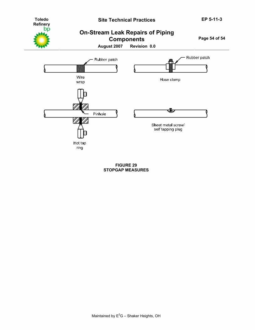
15.3 Stop Gap Repairs
15.3.1 Procedures involving enclosures may require that the LRC perform a stopgap repair before measuring the leaking component. The purpose of the stopgap repair is to diffuse the leak making it less dangerous to work on. In addition, the stopgap repair will help prevent mainlining during the injection process.
15.3.2 Some typical stopgap repair methods are shown in Figure 29.
15.3.3 The stopgap repair is performed prior to measuring so that the dimensions of the stopgap hardware can be included in the data sent to the LRC. This will insure that the LRD chosen will fit and enclose the stopgap repair as well as the leaking component.
15.4 Requirements For Bolting
15.4.1 All bolt tightening procedures used to install LRD shall be in accordance with EP 5-5-4.
15.4.2 The actual bolting procedures used by the LRC shall be submitted for review and approval to the Owner’s Engineer prior to the installation of an LRD that utilizes a bolted connection.
15.5 Sealant Reinjection
15.5.1 All LRDs that require periodic or frequent reinjection of sealant to reseal a recurring leak are cause for concern and indicates that the original installation may have been performed incorrectly. Loss of sealant it typically attributed to loosening of LRD bolting or leakage through LRD perimeter seals.
15.5.2 (*)Reinjection of a sealant into an existing LRD is strictly prohibited without prior approval from the Owner’s Engineer. In general, three reinjections will be permitted on any recurring leak unless the cause is clearly attributable to severe vibration, water hammer or cyclic operation. If the clamp requires more than three reinjections or dynamic service conditions prevail, an engineering review of the initial LRD installation shall be performed to determine the adequacy of the design. Based on this review, the LRD may need to be replaced.
15.5.3 All reinjections into existing installed LRD shall be documented on the appropriate On–Stream Leak Sealing Data Sheet, see EP 5-11-3DS).
16.0 DATA SHEET INSTRUCTIONS
16.1 General An On–Stream Leak Sealing Data Sheet, see EP 5-11-3DS shall be filled out for all on–stream leak repairs.
16.2 Instructions For EP 5–11–3 DS
16.2.1 (*)Part I of the On–Stream Leak Sealing Data Sheet shall be filled out by the Owner’s Engineer responsible for the repair work. Upon completion of Part I, the data sheet shall be given to the LRC who shall complete Part II.
16.2.2 After completion of Parts I and II of the On–Stream Leak Sealing Data Sheet and prior to the installation of the LRD, Part III of the Data Sheet shall be completed.
16.2.3 Part IV of the On–Stream Leak Sealing Data Sheet shall be completed if the LRD is reinjected with sealant, and when the LRD is removed.
Toledo Refinery
Site Technical Practices EP 5-11-3
On-Stream Leak Repairs of Piping Components
August 2007 Revision 0.0
Page 23 of 54
Maintained by E2G – Shaker Heights, OH
16.2.4 All special requirements shall be included on the On–Stream Leak Sealing Data Sheet in the Special Notes Section. In addition, a sketch of the component showing the location of the leak should be supplied.
16.3 Part I - Owner Supplied Information:
16.3.1 Specify the name of Facility, Unit Name, and Zone Number, if applicable.
16.3.2 Specify the name of the Owner’s Engineer who is responsible for the on–stream leak repair. This person will also be the refinery contact for the LRC.
16.3.3 Specify the name of the leaking component including the line or equipment identification number, its size and location in relation to major equipment.
16.3.4 Specify the type of leak.
16.3.5 Specify if the component is currently leaking.
16.3.6 Specify if the leak has caused any damage to the component.
16.3.7 Specify information regarding the leaking fluid including its constituents (give approximate percentages if possible), whether it is categorized as AES (see EP 10-2-1), design and operating conditions, and toxic hazard/protective equipment requirements.
16.3.8 Specify if mainlining (leakage of sealant into the process stream) is a potential problem.
16.3.9 Specify all pertinent information regarding the leaking component, including the presence of refractory lining, if any, whether the component is to be insulated following repairs and whether a strongback is required.
16.3.10 Specify any special material requirements due to the fluid service, see EP 10-2-3.
16.4 Part II - Leak Repair Contractor (LRC) Supplied Information
16.4.1 Specify the name of the company, the name of the sales representative, the blanket contract number and purchase order number.
16.4.2 Specify a brief description of the type of LRD and proposed method of repair.
16.4.3 Specify the LRD assigned serial number.
16.4.4 Specify if all required documentation is provided, see paragraph 9.1.
16.4.5 Specify materials of construction of the LRD.
16.4.6 Specify if the LRD is to be void injected with sealant (or packing for valves), or if perimeter seals are used.
16.4.7 Specify the volume of sealant required for the repair.
16.4.8 Specify the sealant type and properties.
16.4.9 Specify all steps taken to prevent mainlining.
16.4.10 Specify the calculated total weight of the repair device and sealant.
16.4.11 Specify whether the LRD is supported by the leaking component, or whether additional external supports are required.
16.4.12 Specify if the leaking component will be drilled and tapped. If so, specify what size hole and how many times.
16.4.13 Specify the total unbalanced hydraulic force (pressure thrust load) and its direction.
Toledo Refinery
Site Technical Practices EP 5-11-3
On-Stream Leak Repairs of Piping Components
August 2007 Revision 0.0
Page 24 of 54
Maintained by E2G – Shaker Heights, OH
16.4.14 Specify whether strongbacks are required, see paragraph 12.2.
16.5 Part III - Design/Installation Review, Owner’s Engineer
16.5.1 Specify whether the LRD design has been reviewed and approved for installation.
16.5.2 Specify whether a structural integrity check has been performed and documented by the LRC.
16.5.3 Specify whether a site safety review has been performed (escape routes identified, fire extinguishers are available if welding is required, etc.)
16.5.4 Specify whether all pertinent safety items have been discussed with the LRC.
16.5.5 Specify whether safety permits have been issued.
16.5.6 Specify personal protection requirements for clamp installation technicians.
16.5.7 Specify whether a weatherproof tag has been installed on the LRD for identification purposes.
16.5.8 Specify any items that occur during installation of the LRD that may result in inadequate performance.
16.5.9 Specify thickness readings of the component in the vicinity of the leak through a sketch with inspection points labeled and a thickness table.
16.6 Part IV - LRD Removal And Repair, Owner’s Engineer
16.6.1 Specify whether reinjection of the LRD has been performed.
16.6.2 Specify the date of the LRD removal.
16.6.3 Specify (briefly) the repair instituted to the pressure boundary and structural integrity to the component.
Toledo Refinery
Site Technical Practices EP 5-11-3
On-Stream Leak Repairs of Piping Components
August 2007 Revision 0.0
Page 25 of 54
Maintained by E2G – Shaker Heights, OH
17.0 TABLES
TABLE 1 CLAMP SELECTION TABLE
CLAMP
TYPE APPLICATIONS
Advantages Dis–
advantages
Comments High
Temp High Press
Severe Leaks
5.2 Tongue Insert Yes Yes Yes A, B, C, D a 1 5.3 Packing Peripheral Yes No No E, F, G b,c 2,3,4 5.4 Tubing Peripheral Yes Yes Yes E b,c 2,5 5.5 Crunch Groove
Peripheral Yes Yes Yes E,H b,c,d 2
5.6 Tongue & Packing
Peripheral Yes Yes Yes D,I a
KEY TO ADVANTAGES: KEY TO DISADVANTAGES:
A - Relatively easy to install a - Sufficient flange gap is required to B - Tolerant of flange misalignment accommodate clamp tongue C - Can be used on flanges with unequal diameters b - More sensitive to flange misalignment than D - Reduces amount of sealant required insert-type clamps E - Can be used for narrow gap flanges c - No direct means of pressure release F - Can be reused if packing material is replaced d - Use is limited to flanges which have machined G - This is the preferred clamp for use on large surfaces on the flange OD and which are diameter flanges (NPS 16 inch and larger) aligned with very little mismatch. Normally used H - Can be used on any combination of high only when there is a combination of high temperature, high pressure, and severe leaks temperature, very high pressure (above 2000 I - Provides both primary and secondary seals psig), and/or severe leakage.
KEY TO COMMENTS: (1) Generally used when flange gap is 0.375 in. or more. Can be used on gaps less than 0.375 in. if an alternate means of sealant
injection is provided. (2) Because there is no direct means of pressure release, it is advisable to check the ability of the joint fasteners to withstand full–line
pressure over the total flange area. See Paragraph 5.1.7. (3) The packing clamp is limited to a service pressure of 300 psig or less. Can be used for temperatures up to 1200°F, depending on
packing material. (4) Requires less torque on the clamp bolts to achieve a seal than any other peripheral–type clamp. (5) Copper tubing may be used for design temperatures up to 450°F. Stainless steel tubing shall be used above 450°F and in services
designated as AES. May be used for pressures up to 2000 psig and temperatures up to 1400°F.
Toledo Refinery
Site Technical Practices EP 5-11-3
On-Stream Leak Repairs of Piping Components
August 2007 Revision 0.0
Page 26 of 54
Maintained by E2G – Shaker Heights, OH
18.0 FIGURES
Gasket
InjectionValve
Clamp
Sealant
Stud
Flange
Crunch/wipeout grooves
Flange
Clamp
Ear
Injectionport
Pipe
Tongue
FIGURE 1 TYPICAL FLANGE CLAMP
Toledo Refinery
Site Technical Practices EP 5-11-3
On-Stream Leak Repairs of Piping Components
August 2007 Revision 0.0
Page 27 of 54
Maintained by E2G – Shaker Heights, OH
Clamp
RF Flange
InjectionValve
Sealant
Stud
Gasket
FIGURE 2 TONGUE CLAMP
Toledo Refinery
Site Technical Practices EP 5-11-3
On-Stream Leak Repairs of Piping Components
August 2007 Revision 0.0
Page 28 of 54
Maintained by E2G – Shaker Heights, OH
Clamp
RF Flange
Sealant
Stud
Braided Packing
Injection
Valve
Gasket
FIGURE 3 PACKING CLAMP
Toledo Refinery
Site Technical Practices EP 5-11-3
On-Stream Leak Repairs of Piping Components
August 2007 Revision 0.0
Page 29 of 54
Maintained by E2G – Shaker Heights, OH
Clamp
Tubing
RF Flange
Sealant
Stud
InjectionValve
Gasket
FIGURE 4 TUBING CLAMP
Toledo Refinery
Site Technical Practices EP 5-11-3
On-Stream Leak Repairs of Piping Components
August 2007 Revision 0.0
Page 30 of 54
Maintained by E2G – Shaker Heights, OH
Injection
Valve
Flange
Clamp
Sealant
Stud
Gasket
FIGURE 5 CRUNCH GROOVE CLAMP
Toledo Refinery
Site Technical Practices EP 5-11-3
On-Stream Leak Repairs of Piping Components
August 2007 Revision 0.0
Page 31 of 54
Maintained by E2G – Shaker Heights, OH
Clamp
Stud
InjectionValve
Packing
Tounge
Sealant
RF Flange
Gasket
FIGURE 6 TONGUE AND PACKING CLAMP
Toledo Refinery
Site Technical Practices EP 5-11-3
On-Stream Leak Repairs of Piping Components
August 2007 Revision 0.0
Page 32 of 54
Maintained by E2G – Shaker Heights, OH
Injection Valve Capnut
Full Face
Gasket
FF Flange
Sealant
Flange
Stud
FIGURE 7 REPAIRS FOR FLAT FACE FLANGES
WITH FULL FACE GASKETS
Toledo Refinery
Site Technical Practices EP 5-11-3
On-Stream Leak Repairs of Piping Components
August 2007 Revision 0.0
Page 33 of 54
Maintained by E2G – Shaker Heights, OH
Cap NutInjection Valve
Gun Hose
Reservoir
Slot InCap Nut
Stainless Steel Wire
Slot In StudGap
companion flange to seal all leaks. outside diameter and into theAs the gap fills sealant then travels around the gasket
via the anular space of the bolt hole.b: Through the slot which is milled in the cap nut thena: Through the slot which is milled in the stud or
by two paths.From the reservoir sealant can travel to the gap
and injection valve.Sealant enters the cap nut through the gun hose
3.
2.
1.
Sealant Flow - How It Works
FIGURE 8 FLANGE WIRE WRAP
Toledo Refinery
Site Technical Practices EP 5-11-3
On-Stream Leak Repairs of Piping Components
August 2007 Revision 0.0
Page 34 of 54
Maintained by E2G – Shaker Heights, OH
Cap Nut
Wire Wrapping If Needed
Mechanically Peen Edges Of Flange
Slot In The Stud
Injection Valve
Gun Hose
Gap
Slot In Cap Nut
Reservoir
companion flange to seal all leaks. outside diameter and into theAs the gap fills sealant then travels around the gasket
via the anular space of the bolt hole.b: Through the slot which is milled in the cap nut thena: Through the slot which is milled in the stud or
by two paths.From the reservoir sealant can travel to the gap
and injection valve.Sealant enters the cap nut through the gun hose
3.
2.
1.
Sealant Flow - How It Works
FIGURE 9 FLANGE PEENING
Toledo Refinery
Site Technical Practices EP 5-11-3
On-Stream Leak Repairs of Piping Components
August 2007 Revision 0.0
Page 35 of 54
Maintained by E2G – Shaker Heights, OH
Flange Band
Gun Hose
InjectionValve
Slot In Stud
Reservoir
Slot InCap Nut
Gap
CapNut
companion flange to seal all leaks. outside diameter and into theAs the gap fills sealant then travels around the gasket
via the anular space of the bolt hole.b: Through the slot which is milled in the cap nut thena: Through the slot which is milled in the stud or
by two paths.From the reservoir sealant can travel to the gap
and injection valve.Sealant enters the cap nut through the gun hose
3.
2.
1.
Sealant Flow - How It Works
FIGURE 10 FLANGE BANDING
Toledo Refinery
Site Technical Practices EP 5-11-3
On-Stream Leak Repairs of Piping Components
August 2007 Revision 0.0
Page 36 of 54
Maintained by E2G – Shaker Heights, OH
Defect LeakingComponent
BoltsSide bars
End PlateThickness
PerimeterSeal
Cover Thickness
FIGURE 11 TYPICAL BOLTED ENCLOSURE (BOX)
Toledo Refinery
Site Technical Practices EP 5-11-3
On-Stream Leak Repairs of Piping Components
August 2007 Revision 0.0
Page 37 of 54
Maintained by E2G – Shaker Heights, OH
Shutoff adaptor
FIGURE 12 FLANGE ENCLOSURE
Toledo Refinery
Site Technical Practices EP 5-11-3
On-Stream Leak Repairs of Piping Components
August 2007 Revision 0.0
Page 38 of 54
Maintained by E2G – Shaker Heights, OH
FIGURE 13 TYPICAL BOLT–ON STRAIGHT LINE ENCLOSURE
Toledo Refinery
Site Technical Practices EP 5-11-3
On-Stream Leak Repairs of Piping Components
August 2007 Revision 0.0
Page 39 of 54
Maintained by E2G – Shaker Heights, OH
Tee Enclosure Defect
FIGURE 14 FULL TEE ENCLOSURE
Toledo Refinery
Site Technical Practices EP 5-11-3
On-Stream Leak Repairs of Piping Components
August 2007 Revision 0.0
Page 40 of 54
Maintained by E2G – Shaker Heights, OH
FIGURE 15 FULL ELBOW ENCLOSURE
Toledo Refinery
Site Technical Practices EP 5-11-3
On-Stream Leak Repairs of Piping Components
August 2007 Revision 0.0
Page 41 of 54
Maintained by E2G – Shaker Heights, OH
Packing
Tubing
Crunch Teeth
FIGURE 16 ENCLOSURE PERIMETER SEAL TYPES
Toledo Refinery
Site Technical Practices EP 5-11-3
On-Stream Leak Repairs of Piping Components
August 2007 Revision 0.0
Page 42 of 54
Maintained by E2G – Shaker Heights, OH
Vent valve
Non-metallic pipesuch as PVC, fiberglassor concrete
Full packing
Stuffing box
FIGURE 17 FULL PACKING ENCLOSURE FOR NON–METALLIC PIPE
Toledo Refinery
Site Technical Practices EP 5-11-3
On-Stream Leak Repairs of Piping Components
August 2007 Revision 0.0
Page 43 of 54
Maintained by E2G – Shaker Heights, OH
FIGURE 18 FULL VALVE ENCLOSURE
Toledo Refinery
Site Technical Practices EP 5-11-3
On-Stream Leak Repairs of Piping Components
August 2007 Revision 0.0
Page 44 of 54
Maintained by E2G – Shaker Heights, OH
Injection Valve
PerimeterSeal
FIGURE 19 ENCLOSURE FOR AN EXPANSION JOINT
Toledo Refinery
Site Technical Practices EP 5-11-3
On-Stream Leak Repairs of Piping Components
August 2007 Revision 0.0
Page 45 of 54
Maintained by E2G – Shaker Heights, OH
Expansion joint coverused as a box
Field weld tocreate enclosure
Expansion joint box, can be designwith ring type or angled end plates.
NOTE: To use an expansion joint cover as an enclosure to seal a leak,the structural integrity of the cover must be evaluated !
FIGURE 20 EXPANSION JOINT ENCLOSURES ATTACHED BY WELDING
Toledo Refinery
Site Technical Practices EP 5-11-3
On-Stream Leak Repairs of Piping Components
August 2007 Revision 0.0
Page 46 of 54
Maintained by E2G – Shaker Heights, OH
Circumferentialattachment welds
Clamshell ring, installedin two half sections
Clamshell bellows, installed in two half sections witha field longitudinal weld and circumferential attachment welds.
FIGURE 21 EXPANSION JOINT “CLAM SHELL” ENCLOSURE
Toledo Refinery
Site Technical Practices EP 5-11-3
On-Stream Leak Repairs of Piping Components
August 2007 Revision 0.0
Page 47 of 54
Maintained by E2G – Shaker Heights, OH
r
Shut offAdapter
PackingValve
FIGURE 22 ON–STREAM VALVE REPACKING
Toledo Refinery
Site Technical Practices EP 5-11-3
On-Stream Leak Repairs of Piping Components
August 2007 Revision 0.0
Page 48 of 54
Maintained by E2G – Shaker Heights, OH
Sealant
Shutoff adaptor
FIGURE 23 SEALING A LEAKING GATE VALVE SEAT
Toledo Refinery
Site Technical Practices EP 5-11-3
On-Stream Leak Repairs of Piping Components
August 2007 Revision 0.0
Page 49 of 54
Maintained by E2G – Shaker Heights, OH
Center joint
Valve body
Stem
Valve seat
(Open position)
Shutoffadaptor
Ball
Seal
Packingmaterial
FIGURE 24 SEALING A LEAKING BALL VALVE SEAT
Toledo Refinery
Site Technical Practices EP 5-11-3
On-Stream Leak Repairs of Piping Components
August 2007 Revision 0.0
Page 50 of 54
Maintained by E2G – Shaker Heights, OH
Shutoffadaptor
GATE VALVE
GLOBE VALVEShutoff adaptor
FIGURE 25 KILLING A VALVE
Toledo Refinery
Site Technical Practices EP 5-11-3
On-Stream Leak Repairs of Piping Components
August 2007 Revision 0.0
Page 51 of 54
Maintained by E2G – Shaker Heights, OH
Valve bonnet
Shutoffadaptor
Void at tip ofseal ring
Valve body
Pressure seal ring
Retainingring
Typical pressure seal valve
FIGURE 26 SEALING A LEAKING BONNET ON A PRESSURE SEAL VALVE