Pal et al. Vol. 21, No. 8 /August 2004 /J. Opt. Soc. Am. A 1503
Bragg gratings written in Sn–Er–Ge-codopedsilica fiber: investigation of photosensitivity,
thermal stability, and sensing potential
Suchandan Pal
School of Engineering and Mathematical Sciences, City University, London EC1V 0HB, UK, and Central ElectronicsEngineering Research Institute, Pilani, Rajasthan 333 031, India
Tong Sun and Kenneth T. V. Grattan
School of Engineering and Mathematical Sciences, City University, London EC1V 0HB, UK
Scott A. Wade, Stephen F. Collins, and Gregory W. Baxter
Optical Technology Research Laboratory, Victoria University, P.O. Box 14428, Melbourne, Victoria 8001, Australia
Bernard Dussardier and Gerard Monnom
Laboratoire de Physique de la Matiere Condensee, Universite de Nice–Sophia Antipolis, 06 108 Nice Cedex 2,France
Received February 4, 2004; revised manuscript received March 30, 2004; accepted March 31, 2004
1. INTRODUCTIONThe numerous potential applications of UV-induced fiberBragg gratings (FBGs) in fiber optic sensing andtelecommunications1–3 have generated a significant inter-est in this field in recent years. However, two majorfactors—the photosensitivity of the fiber in which thegrating is written and the thermal stability of thegrating—are of prime importance in terms of choosing themost appropriate fiber to use and of the long-term func-tionality of the grating over a wide range of temperatures.B–Ge-codoped fiber has been reported to give a muchhigher level of photosensitivity4 when compared withother fibers, and the technique of hydrogen loading5 canfurther enhance this property of the fiber, but the grat-ings written in these fibers, with or without pretreatmentor posttreatment, are reported to have a much poorerhigh-temperature stability.6–9 Alternatively, reports ofwork on enhanced photosensitivity in Sn-doped germano-silicate fiber10 and Sn–silicate fiber,11–13 have been pub-lished that show improved thermal stability of the grat-ings. Unlike B codoping, Sn codoping does not introducesignificant loss at the telecommunications window of 1.55mm.10–13 In addition, Sn codoping increases the me-chanical strength of the fiber,14 which is very useful both
in telecommunications and sensing applications, with theadded advantage of enhancing the dynamic range of mea-surement of both strain and pressure.
In this work the photosensitivity of Sn–Er-codoped ger-manosilicate fiber and the thermal stability of the FBGswritten into the fiber are reported; the photosensitivity ofthe fiber was analyzed by observing the initial growth ofthe gratings. The thermal stability of the FBGs wasmodeled, on the basis of the power law proposed by Er-dogan et al.15 with an alternative approach that uses amaster aging curve.15,16 This approach explains well theobserved rapid thermal decay of gratings, which was seento be followed by a very slow decay rate for any particulartemperature considered. In the investigation of the ther-mal decay of the gratings, a blueshift observed in theBragg wavelength8,17–19 also can be modeled by using amodified power law. At temperatures higher than ambi-ent, the decay of the UV-induced refractive-index modula-tion (Dnmod) degrades the reflectivity of the grating andat the same time affects the effective refractive index(neff) of the fiber, which is responsible for the shift of theBragg wavelength. However, in this work different de-cay rates of Dnmod and Dneff were observed in terms of thereflectivity decay and the shift of the Bragg wavelength at
2004 Optical Society of America
1504 J. Opt. Soc. Am. A/Vol. 21, No. 8 /August 2004 Pal et al.
various temperatures. These decay rates are related tothe complex phenomenon of the thermal decay of the UV-induced gratings, which has also been confirmed by obser-vation of the visibility factor during the growth of a grat-ing. This was done for various gratings, and the valuesof the visibility factor were also estimated before and af-ter isothermal annealing at various selected tempera-tures. Both Sn41 and Er31 doping have been introducedin the specially fabricated fiber to enhance its propertiesby exploiting amplified spontaneous emission (ASE),which arises from the rare-earth doping in the fiber and,at the same time, the high-temperature sustainability ofthe FBGs written in the fiber that are to be used for sev-eral high-temperature-sensing applications.20
2. EXPERIMENTAL DETAILS AND RESULTSA. Fabrication of Fiber Bragg Gratings and thePhotosensitivity of the Special FiberThe special Er-doped, Sn–germanosilicate fiber (core/cladding diameter 5/125 mm, NA 0.2, cutoff wavelength1400 nm) was designed and fabricated at the Universityof Nice, Nice, France, by using the modified-chemical-vapor-deposition technique. Sn, Er, and Al (1.1 mol/l,0.025 mol/l, and 0.083 mol/l in the solution, respectively)were introduced to achieve both high-temperaturesustainability10–13,20 and a suitable fluorescence spectrumfrom the fiber that would cover the sensing range of theBragg wavelength of the FBG written into it. Al was in-troduced to confine the Er31 ions within the fiber core, toimprove the pumping efficiency of the fiber (to generateASE) as well as to avoid any clustering effects that mayoccur.21
Initially, a type I grating was written in the speciallyfabricated Sn–Er–Ge-codoped, photosensitive fiber by UVlight from a KrF excimer laser (Braggstar-500, TuilaserAG) at 248 nm with a pulse duration of 10 ns and by em-ploying the phase mask technique (phase mask period1061 nm, dimensions 10 mm 3 5 mm; zero order 2.2%;Bragg Photonics Inc., Quebec, Canada). One cylindricalplanoconvex lens (focal length 20 cm) was used to con-verge the laser beam along the fiber length, and the phasemask was placed just in front of the fiber to form a lightinterference pattern with the 11st order and 21st orderof the diffracted light. The grating reflectivity reached;99% within 6 min of exposure time with a laser energyof 12 mJ at 200 Hz and a pulse fluence of ;180 mJ/cm2,but it took a further 5 min to reach the highest achievablepeak reflectivity of 99.6%, with a comparatively slowgrowth rate. A redshift of the Bragg wavelength wasalso observed with the UV exposure during the growth ofthe grating, where the on-line measurement of the grat-ing spectrum was made by using an HP-86140A (AgilentTechnologies, Palo Alto, Calif.) optical spectrum analyzer.The consistency of this result was observed by fabricatinga number of gratings under the same conditions.
With a reasonable assumption that the gratings wereall uniform (sample tests confirmed this), the amplitudeof the refractive-index modulation (Dnmod) was estimatedby using the following equation,1,2
Dnmod 5 @l/pLn~V !#tanh21~R !1/2, (1)
where l is the operating wavelength for a grating lengthL of reflectivity R with an overlap function of the fibern(V) 5 $1 2 @1/2.405(lcutoff /l)#2%. The correspondingestimated value of Dnmod was ;3.3 3 1024 for a gratinglength of ;6.5 mm. Following the UV exposure duringthe grating fabrication, the Bragg wavelength shift wasobserved to be ;0.82 nm toward the longer wavelengthside, which corresponds to an increase in the effective re-fractive index of the fiber core (Dneff) of ;7.7 3 1024, thishaving been determined with the equation
Dneff 5 ~Dlb!/2L, (2)
where Dlb is the Bragg wavelength shift during the fab-rication process of the grating and L is the grating period,i.e., half of the phase mask period. Figure 1 shows thevariation of the amplitude of the refractive-index modula-tion (Dnmod) and the effective refractive index (neff) withthe UV exposure time during the growth of the grating.The evolution of the grating reflectivity and the corre-sponding Bragg wavelength as a function of UV exposuretime are shown as an inset in Fig. 1.
To investigate the process of photosensitivity in the ex-periment (whether it is based on a single-photon or mul-tiphoton process),11,12,22 gratings were fabricated with dif-ferent levels of laser fluence and a measurement of thegrowth of the gratings was carried out. If the initialgrowth of the refractive-index modulation (Dnmod) is as-sumed to be proportional to the UV exposure time t with alaser fluence of Ip , then this can be expressed as
Dnmod 5 ~Ip!gt, (3)
and the growth rate can be represented as
G 5 d/dt~Dnmod! 5 ~Ip!g, (4)
where the numerical coefficient g, through which the pro-cess of photosensitivity is estimated, can be determinedfrom the slope of the growth-rate-versus-laser-fluencegraph as a logarithmic plot. This is shown in Fig. 2 forthis experiment. The slope of the graph was evaluated inthis case to be 0.97 (60.05), giving evidence that the pho-tosensitivity of the fiber for its initial growth at the laser
Fig. 1. Variation of the amplitude of refractive-index modula-tion and the effective refractive index with the UV exposure timefor a laser fluence of ;180 mJ/cm2/pulse. The inset shows theevolution of the grating reflectivity and the Bragg wavelengthshift during the growth of the FBG.
Pal et al. Vol. 21, No. 8 /August 2004 /J. Opt. Soc. Am. A 1505
fluence used (at a wavelength of 248 nm) is dominated bya single-photon process, although there are some reportsin the literature that the total growth of the photorefrac-tivity may arise from not only a single-photon but from amultiphoton process.12,22
B. Analysis of the Thermal Stability of the GratingsFor an analysis of thermal stability, a series of nearlyidentical gratings of reflectivity ;90% was fabricated inthe same Sn–Er–Ge-codoped fiber. Grating reflectivitieswere controlled by stabilizing the energy, pulse frequency,and the exposure time of the excimer laser. The esti-mated values of Dnmod and Dneff [by use of Eqs. (1) and(2)] were ;1.8 3 1024 and ;4.5 3 1024, respectively.No saturation was required in this work because the re-flectivities were measured in this study by consideringonly the minimum of the transmission spectrum at theBragg wavelength, not the spectral width, which is di-rectly related to Dnmod for strong gratings.16
The thermal degradation of the FBGs with time wasmonitored separately at temperatures of 100, 300, 500,700, 800, and 900 °C by placing the individual gratingsvery carefully (so that there was no excess strain on thegrating) in a well-calibrated CARBOLITE tube oven(Type MTF 12/38/400). Temperatures were kept con-stant for each measurement over a period of '8 h, afterwhich the gratings were returned slowly to room tem-perature to measure their decay in reflectivity and the ir-reversible blueshift of Bragg wavelength. The real-timereflectivities of the gratings were measured from thetransmission spectra observed on the optical spectrumanalyzer. At each temperature, a fast decay of the grat-ing followed by a very slow decay was observed. Thethermal decay was modeled in terms of the normalizedintegrated-coupling coefficient (NICC, h) because theintegrated-coupling coefficient (ICC) is directly propor-tional to the peak reflectivity. The peak reflectivity of thegrating at any time can be calculated by
R 5 ~1 2 Tmin!, (5)
Fig. 2. Dependence of the initial grating growth rate on the la-ser pulse fluence. The solid line is the linear regression with aslope of 0.97.
where Tmin is the transmission minimum of the grating atthe Bragg wavelength (lb). The value of ICC can be cal-culated as
ICC 5 tanh21~R1/2!, (6)
which can be used subsequently for the evaluation ofNICC (h) as
h 5 @tanh21~Rt,T1/2 !/tanh21~R0,RT
1/2 !#, (7)
where Rt,T and R0,RT are the reflectivities after an an-nealing time t at a temperature T and the initial reflec-tivity at room temperature (;23 °C), respectively.
1. Decay in Refractive-Index Modulation (Dnmod) Basedon the Power LawUsing the experimental data obtained, we modeled thethermal decay characteristics according to the power-lawfunction proposed by Erdogan et al.15 This can be ex-pressed as
h 5 1/@1 1 A~t/t1!a#, (8)
where t, A, and a are the decay time in minutes, thepower-law factor, and the power-law decay coefficient, re-spectively. To keep the dimensions consistent, a time,t1 5 1 min, was introduced. Both A and a are dimen-sionless in this form but they are temperature-dependent.It was found that the model fits the experimental datareasonably well, except for a few data at 900 °C, whichlikely arise from the uncertainties in the measurementfor very low values of reflectivities with the oscillatorypattern of the reference power spectrum. Figure 3 showsthe thermal decay characteristics along with a graph fit-ted to the model (solid curves). The set of values of A anda was calculated from the experimental points for eachtemperature according to Eq. (8). Following that, A anda were plotted against temperature to evaluate the tem-perature dependence of these parameters, this beingshown in Figs. 4 and 5. The variation of a with tempera-ture was assumed to be linear, passing through zero onthe temperature axis (K), and the temperature depen-dence of this parameter can be expressed as
Fig. 3. Isothermal decay of the FBGs written in an Sn–Er–Ge-codoped fiber with time in terms of the NICC at various tempera-tures.
1506 J. Opt. Soc. Am. A/Vol. 21, No. 8 /August 2004 Pal et al.
a 5 T/TR , (9)
where T is the temperature in Kelvin, and from the slopeof the linear fit the value of TR 5 5563 K can be esti-mated. Figure 5 shows a plot of A with temperature on alinear scale; where the value of A was evaluated by expo-nential growth fitting, the nature of which can be writtenas
A 5 A0 exp~aT ! (10)
with A0 5 1.54 3 1023 and a 5 6.19 3 1023 K21. Thevalues of TR , A, and a in this work are slightly differentfrom the brief results reported by Brambilla et al.13 forSn–silicate fiber. The variation of the composition of thefiber and the dopants (specifically, selecting Er and Ge, inaddition to Sn) and the concentrations of the dopantswithin the core of the photosensitive fibers used are mostlikely to have caused these differences in the values ofthese parameters.
Fig. 4. Linear fit for the power-law decay coefficient a.
Fig. 5. Exponential fit for the power-law factor A.
2. Decay in Refractive-Index Modulation (Dnmod) Basedon the Master Aging CurveThe success in the use of the power law to represent thedecay of the gratings depends on the a-versus-T andA-versus-T relationships being expressed by Eqs. (9) and(10). These may, however, not always be correct, as a de-viation of the regression may be observed from the experi-mental data for a, particularly at lower temperatures.This is due mainly to the large uncertainty in the value ofICC due to the measurement errors in Tmin for the verysmall grating decay at lower temperatures. Thus in thiswork, attempts were made to fit the data from the accel-erated aging experiments at 100, 300, 500, 700, 800, and900 °C to obtain a ‘‘master curve’’ by using the aging curveapproach8,13,15,16,23 to predict the operational lifetime ofthe grating. In this approach, it is assumed that thegrating inscription causes a broad distribution of the ac-tivation energy of thermodynamically unstable traps, andthe aging of any grating at any time t and temperature Tcan be described by an aging parameter8,13,15,16,23 Ed (thedemarcation energy) by
Ed 5 kBT ln~nt !, (11)
where kB is Boltzmann’s constant and n is a frequencyterm that can be obtained from the sets of data obtainedat various temperatures (say, 100, 300, 500, 700, 800, and900 °C) fitted together through an iterative process. Thecorrect shape of the master curve can also be deducedfrom the power-law expression8,15,23 and is described bythe equation
h~Ed! 5 1/$1 1 exp@~Ed 2 DE !/kBTR#%, (12)
where the total number of the trapped carriers at time twas assumed to be proportional to the experimentally de-termined values of h. Figure 6 illustrates the master ag-ing curve for the grating with the same (earlier) experi-mental data. For this plot, the optimum value of n usedwas 1.54 3 1013 Hz for the best fit to a single mastercurve. After the establishment of the master agingcurve, the degradation of the grating for any combinationof time and temperature can be projected, as discussedbelow.
Fig. 6. NICC as a function of demarcation energy Ed for thegrating. The frequency term (n) used for this plot is 1.543 1013 Hz.
Pal et al. Vol. 21, No. 8 /August 2004 /J. Opt. Soc. Am. A 1507
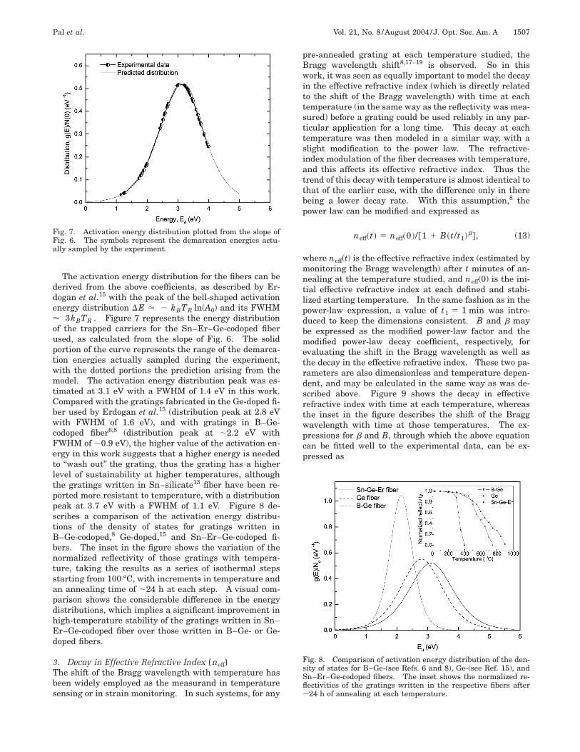
The activation energy distribution for the fibers can bederived from the above coefficients, as described by Er-dogan et al.15 with the peak of the bell-shaped activationenergy distribution DE ' 2 kBTR ln(A0) and its FWHM' 3kBTR . Figure 7 represents the energy distributionof the trapped carriers for the Sn–Er–Ge-codoped fiberused, as calculated from the slope of Fig. 6. The solidportion of the curve represents the range of the demarca-tion energies actually sampled during the experiment,with the dotted portions the prediction arising from themodel. The activation energy distribution peak was es-timated at 3.1 eV with a FWHM of 1.4 eV in this work.Compared with the gratings fabricated in the Ge-doped fi-ber used by Erdogan et al.15 (distribution peak at 2.8 eVwith FWHM of 1.6 eV), and with gratings in B–Ge-codoped fiber6,8 (distribution peak at ;2.2 eV withFWHM of ;0.9 eV), the higher value of the activation en-ergy in this work suggests that a higher energy is neededto ‘‘wash out’’ the grating, thus the grating has a higherlevel of sustainability at higher temperatures, althoughthe gratings written in Sn–silicate13 fiber have been re-ported more resistant to temperature, with a distributionpeak at 3.7 eV with a FWHM of 1.1 eV. Figure 8 de-scribes a comparison of the activation energy distribu-tions of the density of states for gratings written inB–Ge-codoped,8 Ge-doped,15 and Sn–Er–Ge-codoped fi-bers. The inset in the figure shows the variation of thenormalized reflectivity of those gratings with tempera-ture, taking the results as a series of isothermal stepsstarting from 100 °C, with increments in temperature andan annealing time of ;24 h at each step. A visual com-parison shows the considerable difference in the energydistributions, which implies a significant improvement inhigh-temperature stability of the gratings written in Sn–Er–Ge-codoped fiber over those written in B–Ge- or Ge-doped fibers.
3. Decay in Effective Refractive Index (neff)The shift of the Bragg wavelength with temperature hasbeen widely employed as the measurand in temperaturesensing or in strain monitoring. In such systems, for any
Fig. 7. Activation energy distribution plotted from the slope ofFig. 6. The symbols represent the demarcation energies actu-ally sampled by the experiment.
pre-annealed grating at each temperature studied, theBragg wavelength shift8,17–19 is observed. So in thiswork, it was seen as equally important to model the decayin the effective refractive index (which is directly relatedto the shift of the Bragg wavelength) with time at eachtemperature (in the same way as the reflectivity was mea-sured) before a grating could be used reliably in any par-ticular application for a long time. This decay at eachtemperature was then modeled in a similar way, with aslight modification to the power law. The refractive-index modulation of the fiber decreases with temperature,and this affects its effective refractive index. Thus thetrend of this decay with temperature is almost identical tothat of the earlier case, with the difference only in therebeing a lower decay rate. With this assumption,8 thepower law can be modified and expressed as
neff~t ! 5 neff~0 !/@1 1 B~t/t1!b#, (13)
where neff(t) is the effective refractive index (estimated bymonitoring the Bragg wavelength) after t minutes of an-nealing at the temperature studied, and neff(0) is the ini-tial effective refractive index at each defined and stabi-lized starting temperature. In the same fashion as in thepower-law expression, a value of t1 5 1 min was intro-duced to keep the dimensions consistent. B and b maybe expressed as the modified power-law factor and themodified power-law decay coefficient, respectively, forevaluating the shift in the Bragg wavelength as well asthe decay in the effective refractive index. These two pa-rameters are also dimensionless and temperature depen-dent, and may be calculated in the same way as was de-scribed above. Figure 9 shows the decay in effectiverefractive index with time at each temperature, whereasthe inset in the figure describes the shift of the Braggwavelength with time at those temperatures. The ex-pressions for b and B, through which the above equationcan be fitted well to the experimental data, can be ex-pressed as
Fig. 8. Comparison of activation energy distribution of the den-sity of states for B–Ge-(see Refs. 6 and 8), Ge-(see Ref. 15), andSn–Er–Ge-codoped fibers. The inset shows the normalized re-flectivities of the gratings written in the respective fibers after;24 h of annealing at each temperature.
1508 J. Opt. Soc. Am. A/Vol. 21, No. 8 /August 2004 Pal et al.
b 5 T/Tl with Tl 5 5943 K, (14)
B 5 B0 exp~bT !, B0 5 5.20 3 1026,
b 5 2.66 3 1023 K21. (15)
In Fig. 9 the modified power-law model is seen to fit wellto the experimental points showing the decay in the effec-tive refractive index, which results in the shift in theBragg wavelength. Thus the predicted shift in the Braggwavelength of the grating after any time, at some lowertemperature, may be simulated with the above values ofthe parameters evaluated.
From the parameters evaluated, and by using thepower law, the modified power law, and the master agingcurve approach, the lifetime of the grating can be esti-mated in terms of the decay in the reflectivity and theshift in the Bragg wavelength. Figure 10 describes thepredicted decay in reflectivity and the shift in the Braggwavelength for a pre-annealed grating written in a Sn–Er–Ge-codoped fiber at 500 °C for a period of ;10 yr.The results show that the NICC reaches a value of 0.66
Fig. 9. Thermal degradation of the FBGs with time in terms ofthe effective refractive index at various temperatures. The insetshows the corresponding blueshift in the Bragg wavelengths.
Fig. 10. Thermal response and thermal sensitivity of the grat-ings written in an Sn–Er–Ge-codoped fiber after proper anneal-ing of the sample.
with a shift of the Bragg wavelength of 0.18 nm after onlyone day when the grating remains at a temperature of500 °C, which is almost half of the total decay that wouldoccur at that temperature over a predicted period of 10 yr.A negligible difference in the decay paths has been ob-served from the figure when the power law and the mas-ter aging curve are compared. This is mainly due to theconsideration of the pre-annealed grating in this case, sothat there is no truncation of the initial distribution of theactivation energy.16
C. High-Temperature-Sensing PotentialOne of the most important physical parameters for manyindividual applications, temperature, can be measuredfrom a calibration of the shift of the Bragg wavelength ofthe grating. Sn doping in the fiber enhances the thermalstability10–13 of the grating, resulting in a wider range ofmeasurement of temperature and establishing the primereason for choosing a fiber with this element as one of thedopants of the core during fabrication. Temperature-induced reversible and irreversible changes in the Braggwavelengths8,24 of the gratings were observed when thethermal decay of the gratings was analyzed. For sensingpurposes, to enable a reproducible sensor probe to be de-veloped, the irreversible changes of the Bragg wavelengthshould be eliminated to achieve repeatable measurementdata by a well-defined process of annealing that stabilizesthe gratings and allows only reversible changes in theBragg wavelengths, thus resulting in a high level of re-peatability over useful ranges of measurement for sensorapplications.
In this work, a grating was annealed properly at 850 °Cfor ;10 h before being used for temperature measure-ment up to 800 °C (from room temperature in incrementsof 20 °C) by monitoring the reflection spectrum of thegrating, by use of only the temperature-induced revers-ible changes in the Bragg wavelength. A settling time of15 min was allowed at each temperature to ensure a ther-mal equilibrium between the grating and the oven beforerecording data for several cycles of both ascending andthe descending temperatures. The measured data forthe ascending and the descending temperature cycles, interms of the Bragg wavelength change with temperature,were observed to be quite consistent over a number of re-peated measurements, with a wavelength uncertainty of60.01 nm (the peak–dip resolution of the optical spec-trum analyzer used). The variation of the Bragg wave-length with temperature was found to be slightly nonlin-ear, and the temperature-dependent thermal sensitivityvalues of the grating were estimated to be 10.6 pm/°C and16.8 pm/°C at room temperature (;23 °C) and 800 °C, re-spectively. The thermal response of the grating, alongwith its temperature sensitivity, is plotted in Fig. 11.
This specially fabricated fiber has the added advantageof yielding fluorescence generated by the ASE caused bythe rare-earth (Er31) doping. This has been shown to bevery useful in the design of special fiber amplifier andfluorescence-based temperature sensing devices.25,26 Si-multaneous measurement of strain and temperature overa wide range of temperature can also be achieved, basedon the temperature dependence of the fluorescence peakpower ratio of the ASE in rare-earth-doped fiber and the
Pal et al. Vol. 21, No. 8 /August 2004 /J. Opt. Soc. Am. A 1509
dual functionality of the FBG.20,26 Figure 12 shows theASE spectra obtained from this fiber, of length 10 cm,with a grating written in one end, where the fluorescence-peak-power-ratio approach may be applied for wave-lengths of 1535 and 1552 nm.
3. DISCUSSIONAlthough the thermal stability of the Bragg gratings writ-ten into Sn–Er-doped, germanosilicate fiber has beenanalyzed in this paper, both in terms of the NICC and theshift in the Bragg wavelength, both of which are directlyrelated to the refractive-index modulation and the effec-tive refractive index of the fiber, accurate prediction ofgrating stability remains difficult because of the highlycomplex phenomena associated with the grating decay, asdiscussed below.
Although the possibility of multiple peaks developingin the energy distribution has been suggested by observa-
Fig. 11. Fluorescence spectra obtained at various temperaturesfrom ;10-cm long Sn–Er–Ge-codoped fiber. The dip in the spec-tra indicates the grating written into the fiber.
Fig. 12. Prediction of thermal decay of the grating at 500 °C ac-cording to the power law and master aging curve, along with theblueshift of the Bragg wavelength of the grating.
tion of a slight nonsmooth thermal decay in the gratingreflectivity (see the inset of Fig. 8), only one peak hasbeen considered in this work, to simplify the analysis ofthe complexity in the energy distribution arising from thepresence of various dopants in the fiber (i.e., Ge, Sn, andEr) at different concentrations. An energy distributionwith multiple peaks has also been reported by Rathjeet al.27 for gratings written in a H-loaded fiber. In fact,an energy distribution showing multiple peaks may be re-alized in this work by considering lower-temperature (be-low 700 °C) and higher-temperature (above 700 °C) iso-thermal tests separately to evaluate the decay coefficientsin two different thermal states, and combining the respec-tive energy distributions.
Second, the temperature-induced reversible changes inthe grating reflectivity,8,24 where very accurate measure-ment is required, has not been considered in this work be-cause of the limited uncertainty in the measurement ofthe reference power level during reflectivity monitoring ofthe grating. The oscillatory pattern of the referencepower level was possibly caused by the mismatch of therefractive index between the Sn–Er–Ge-codoped fiberused and the fibers in the connectors to the light sourceand the detector, as well as by the interference betweenthe core and cladding modes that occurs in the fiber sec-tion within the splice intersections27 for the measurementof the reflectivity. The above-mentioned effect will causelittle further degradation of the gratings, consideration ofwhich has not been included here, although it has beendiscussed previously for gratings in B–Ge-codoped fiberby some of the authors.8
The third limitation is caused by the step–stress agingeffect,8,28 which results in slightly different values of theattempted frequency n for the master aging curve, indi-cating the hidden parallel degradation, which may beruled out by use of demarcation mapping,28 although fullassurance of the reliability of the accelerated testing can-not be given because of the highly complex nature of thegrating decay mechanism.
Finally, although the temperature-induced reversibleand irreversible changes in the Bragg wavelength shiftwere observed for any pre-annealed grating (although, forthe chemical composition gratings,29 the irreversiblechanges in the Bragg wavelength have not been observedas the grating passed through the first stage of annealingduring the high-temperature treatment that occurred atthe time of its formation), only the irreversible changeshave been considered in this study of the decay of the ef-fective refractive index with temperature by taking theBragg wavelength at the beginning of the experiment(time t 5 01) as the reference. To separate the irrevers-ible from the reversible shift of the Bragg wavelength, theBragg wavelength at room temperature (say, 23 °C) wasmeasured initially as lRT before annealing. If the Braggwavelengths after annealing at any temperature and atthe room temperature to which the grating returned werelFinal and lReturn , respectively, then (lFinal 2 lReturn) canbe considered the reversible shift whereas (lRT2 lReturn) is the irreversible shift of the Bragg wave-length. In fact, this type of analysis has also been con-sidered in the calculation of the decay in the effective re-fractive index (Dneff) of the fiber to evaluate the fringe
1510 J. Opt. Soc. Am. A/Vol. 21, No. 8 /August 2004 Pal et al.
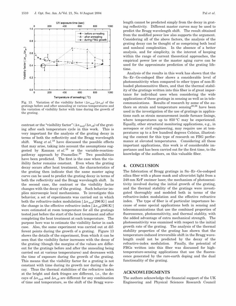
contrast or the ‘‘visibility factor’’ (Dnmod /Dneff) of the grat-ing after each temperature cycle in this work. This isvery important for the analysis of the grating decay interms of both the reflectivity and the Bragg wavelengthshift. Wang et al.18 have discussed the possible effectsthat may arise, taking into account the assumptions sug-gested by Kannan et al.16 or the variable-reaction-pathway approach by Poumellec.30 Two possibilitieshave been predicted. The first is the case when the vis-ibility factor remains constant. Even when the gratingdecay occurs after heat treatment, the characteristics ofthe grating then indicate that the same master agingcurve can be used to predict the grating decay in terms ofboth the reflectivity and the Bragg wavelength shift. Inthe second case, the contrast or the visibility factorchanges with the decay of the grating. Such behavior im-plies microscopic local mechanisms. To investigate thisbehavior, a set of experiments was carried out in whichboth the refractive-index modulation @Dnmod(296 K)# andthe change in the effective refractive index @Dneff(296 K)#were estimated at room temperature for all the gratingstested just before the start of the heat treatment and aftercompleting the heat treatment at each temperature. Thepurpose here was to estimate the visibility factor in eachcase. Also, the same experiment was carried out at dif-ferent points during the growth of a grating. Figure 13shows the details of the experiment, from which it can beseen that the visibility factor increases with the decay ofthe grating (though the margins of the values are differ-ent for the gratings before and after the annealing beingcarried out at various temperatures) and decreases withthe time of exposure during the growth of the grating.This means that the visibility factor for a grating is notconstant with time during its growth nor during the de-cay. Thus the thermal stabilities of the refractive indexat the bright and dark fringes are different, i.e., the de-cays of Dnmod and Dneff are different for any combinationof time and temperature, so the shift of the Bragg wave-
Fig. 13. Variation of the visibility factor (Dnmod /Dneff) of thegratings before and after annealing at various temperatures andthe variation of visibility factor with time during the growth ofthe grating.
length cannot be predicted simply from the decay in grat-ing reflectivity. Different master curves may be used topredict the Bragg wavelength shift. The result obtainedfrom the modified power law also supports the argument.Considering all of the above factors, the analysis of thegrating decay can be thought of as comprising both localand nonlocal complexities. In the absence of a betteranalysis, and for simplicity, in the interest of keepingwithin the range of current theoretical approaches, theempirical power law or the master aging curve can beused for the approximate prediction of the grating life-time.
Analysis of the results in this work has shown that theSn–Er–Ge-codoped fiber shows a considerable level ofphotosensitivity when compared to other types of non-H-loaded photosensitive fibers, and that the thermal stabil-ity of the gratings written into this fiber is of great impor-tance for individual uses when considering the wideapplications of these gratings in sensing as well as in tele-communications. Results of research by some of the au-thors on strain and temperature sensing20,26 have beenused in the investigation of the use of gratings in applica-tions such as strain measurement inside furnace linings,where temperatures up to 850 °C may be experienced.Equally, other structural monitoring applications, e.g., inaerospace or civil engineering, may require use at tem-peratures up to a few hundred degrees Celsius, illustrat-ing the context for this type of research on FBG perfor-mance at elevated temperatures. Considering all theseimportant applications, this work is of considerable im-portance and has been carried out for the first time, to theknowledge of the authors, on this valuable fiber.
4. CONCLUSIONThe fabrication of Bragg gratings in Sn–Er–Ge-codopedsilica fiber with a phase mask and ultraviolet light from a248-nm KrF excimer laser, the mechanism of photosensi-tivity involved during the initial growth of the grating,and the thermal stability of the gratings were investi-gated thoroughly and modeled both in terms of therefractive-index modulation and the effective refractiveindex. The type of fiber is of particular importance be-cause of some special applications both in sensing andtelecommunications that use the combined properties offluorescence, photosensitivity, and thermal stablity, withthe added advantage of extra mechanical strength. Thephotosensitivity was examined with respect to the initialgrowth rate of the grating. The analysis of the thermalstability properties of the grating has shown that thetemperature-induced irreversible shift in the Bragg wave-length could not be predicted by the decay of therefractive-index modulation. Finally, the potential ofFBGs written into this fiber was discussed for high-temperature-sensing applications that use the fluores-cence generated by the rare-earth doping and the dualfunctionality of the grating.
ACKNOWLEDGMENTSThe authors acknowledge the financial support of the UKEngineering and Physical Sciences Research Council
Pal et al. Vol. 21, No. 8 /August 2004 /J. Opt. Soc. Am. A 1511
(EPSRC) through various schemes and support from theAustralian Research Council (ARC). S. Pal is thankful tothe Commonwealth Scholarship Commission in the UKfor providing a Commonwealth Scholarship and to theCentral Electronics Engineering Research Institute(CEERI), Pilani, India, for the study-leave abroad.
S. Pal, the corresponding author, can be reached bye-mail at [email protected].
REFERENCES1. A. Othonos and K. Kalli, Fiber Bragg Gratings: Funda-
mentals and Applications in Telecommunications and Sens-ing (Artech House, Boston, Mass., 1999).
2. R. Kashyap, Fiber Bragg Gratings, Optics and PhotonicsSeries (Academic, San Diego, Calif., 1999).
3. K. T. V. Grattan and B. T. Meggitt, eds., Optical Fiber Sen-sor Technology, Vol. 2 (Chapman and Hall, London, 1998).
4. D. L. Williams, B. J. Ainslie, J. R. Armitage, R. Kasyap, andR. Campbell, ‘‘Enhanced UV-photosensitivity in boroncodoped germanosilicate fibers,’’ Electron. Lett. 29, 45–47(1993).
5. P. J. Lemaire, R. M. Atkins, V. Mizrahi, and W. A. Reed,‘‘High pressure H2 loading as a technique for achieving ul-trahigh UV photosensitivity and thermal sensitivity inGeO2-doped optical fibers,’’ Electron. Lett. 29, 1191–1193(1993).
6. S. R. Baker, H. N. Rourke, V. Baker, and D. Goodchild,‘‘Thermal decay of fibre Bragg gratings written in boronand germanium codoped silica fiber,’’ J. Lightwave Technol.15, 1470–1477 (1997).
7. L. Dong and W. F. Liu, ‘‘Thermal decay of fiber Bragg grat-ings of positive and negative index changes formed at 193nm in a boron co-doped germanosilicate fiber,’’ Appl. Opt.36, 8222–8226 (1997).
8. S. Pal, J. Mandal, T. Sun, and K. T. V. Grattan, ‘‘Analysis ofthermal decay and prediction of operational lifetime for atype I boron-germanium codoped fiber Bragg grating,’’ Appl.Opt. 42, 2188–2197 (2003).
9. I. Riant and B. Poumellec, ‘‘Thermal decay of gratings writ-ten in hydrogen-loaded germanosilicate fibers,’’ Electron.Lett. 34, 1603–1604 (1998).
10. L. Dong, J. L. Cruz, L. Reekie, M. G. Xu, and D. N. Payne,‘‘Enhanced photosensitivity in tin-codoped germanosilicateoptical fibers,’’ IEEE Photon. Technol. Lett. 7, 1048–1050(1995).
11. G. Brambilla, V. Pruneri, and L. Reekie, ‘‘Photorefractiveindex gratings in SnO2 :SiO2 optical fibers,’’ Appl. Phys.Lett. 76, 807–809 (2000).
12. G. Brambilla and V. Pruneri, ‘‘Enhanced photorefractivityin tin-doped silica optical fibers (Review),’’ IEEE J. Sel. Top.Quantum Electron. 7, 403–408 (2001).
13. G. Brambilla and H. Rutt, ‘‘Fiber Bragg gratings with en-hanced thermal stability,’’ Appl. Phys. Lett. 80, 3259–3261(2002).
14. K. Imamura, T. Nakai, Y. Sudo, and Y. Imada, ‘‘High reli-ability tin-codoped germanosilicate fibre Bragg gratingsfab-ricated by direct writing method,’’ Electron. Lett. 34, 1772–1773 (1998).
15. T. Erdogan, V. Mizrahi, P. J. Lemaire, and D. Monoroe, ‘‘De-cay of ultraviolet-induced fiber Bragg gratings,’’ J. Appl.Phys. 76, 73–80 (1994).
16. S. Kannan, J. Z. Y. Guo, and P. J. Lemaire, ‘‘Thermal sta-bility analysis of UV-induced fiber Bragg gratings,’’ J.Lightwave Technol. 15, 1478–1483 (1997).
17. K. E. Chisholm, K. Sugden, and I. Bennion, ‘‘Effects of ther-mal annealing on Bragg fibre gratings in boron/germaniumco-doped fibre,’’ J. Phys. D 31, 61–64 (1998).
18. Q. Wang, A. Hidayat, P. Niay, and M. Douay, ‘‘Influence ofblanket postexposure on the thermal stability of the spec-tral characteristics of gratings written in a telecommunica-tion fiber using light at 193 nm,’’ J. Lightwave Technol. 18,1078–1083 (2000).
19. T. Sun, S. Pal, J. Mandal, and K. T. V. Grattan, ‘‘FibreBragg grating fabrication using fluoride excimer laser forsensing and communication applications,’’ Central LaserFacility Annual Report 2001/2002 (Central Laser Facility,Rutherford Appleton Laboratory, Oxfordshire, UK, 2002),pp. 147–149.
20. S. Pal, T. Sun, K. T. V. Grattan, S. A. Wade, S. F. Collins, G.W. Baxter, B. Dussardier, and G. Monnom, ‘‘Bragg gratingperformance in Er–Sn-doped germanosilicate fiber for si-multaneous measurement of wide range temperature (to500 °C) and strain,’’ Rev. Sci. Instrum. 74, 4858–4862(2003).
21. M. J. F. Digonnet, Rare-Earth-Doped Fiber Lasers and Am-plifiers (Marcel Dekker, New York, 1993).
22. J. Albert, B. Malo, K. O. Hill, F. Bilodeau, D. C. Jackson,and S. Theriault, ‘‘Comparison of one-photon and two-photon effects in the photosensitivity of germanium-dopedsilica optical fibers exposed to intense ArF excimer laserpulses,’’ Appl. Phys. Lett. 67, 3529–3531 (1995).
23. D. Razafimahatratra, P. Niay, M. Douay, B. Poumellec, andI. Riant, ‘‘Comparison of isochronal and isothermal decaysof Bragg gratings written through continuous-wave expo-sure of an unloaded germanosilicate fiber,’’ Appl. Opt. 39,1924–1933 (2000).
24. A. Hidayat, Q. Wang, P. Niay, M. Douay, B. Poumellec, andI. Riant, ‘‘Temperature-induced reversible changes in thespectral characteristics of fiber Bragg gratings,’’ Appl. Opt.40, 2632–2641 (2002).
25. Y. Imai and T. Hokazono, ‘‘Fluorescence-based temperaturesensing using erbium-doped optical fibers with 1.48 mmpumping,’’ Opt. Rev. 4, 117–120 (1997).
26. S. A. Wade, D. I. Forsyth, Q. Guofu, and K. T. V. Grattan,‘‘Fiber optic sensor for dual measurement of temperatureand strain using a combined fluorescent lifetime decay andfiber Bragg grating technique,’’ Rev. Sci. Instrum. 72, 3186–3190 (2001).
27. J. Rathje, M. Kristensen, and J. E. Pedersen, ‘‘Continuousanneal method for characterizing the thermal stability ofultraviolet Bragg gratings,’’ J. Appl. Phys. 88, 1050–1055(2000).
28. M. J. LuValle, L. R. Copeland, S. Kannan, J. B. Judkins,and P. J. Lemaire, ‘‘A strategy for extrapolation in acceler-ated testing,’’ Bell Labs Tech. J., July–September 1998,pp. 139–147.
29. M. Fokine, ‘‘Formation of thermally stable chemical compo-sition gratings in optical fibers,’’ J. Opt. Soc. Am. B 19,1759–1765 (2002).
30. B. Poumellec, ‘‘Links between writing and erasure (or sta-bility) of Bragg gratings in disordered media,’’ J. Non-Cryst.Solids 239, 108–115 (1998).