22
G-SERIES EXCAVATORS 75G / 85G THE GAP BRIDGE

G-SERIES
EXCAVATORS
75G / 85G
THE GAPBRIDGE


RELIABLE PERFORMANCE
+
MIDSIZEMIGHT.

FIT IN MORE PRODUCTIVITY.
Neither too big nor too small, these right-size excavators are the perfect solution for a wide variety
of tasks. Their reduced-tail-swing configurations provide extra flexibility, enabling them to maneuver
nimbly and work efficiently in and around congested conditions. What’s more, the 85G comes equipped
with an independent-swing boom that enables work close to curbs, parallel to structures, or alongside
traffic. Their spacious, comfortable cabs feature easy-to-navigate enhanced LCD monitors that let
operators easily dial-in a wealth of machine info and functionality. See how the 75G and 85G can be
a perfect fit for your equipment fleet for years to come.
4
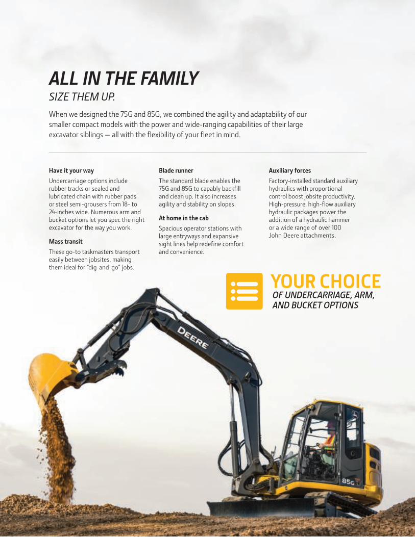
ALL IN THE FAMILYSIZE THEM UP.
When we designed the 75G and 85G, we combined the agility and adaptability of our
smaller compact models with the power and wide-ranging capabilities of their large
excavator siblings — all with the flexibility of your fleet in mind.
Have it your way
Undercarriage options include rubber tracks or sealed and lubricated chain with rubber pads or steel semi-grousers from 18- to 24-inches wide. Numerous arm and bucket options let you spec the right excavator for the way you work.
Mass transit
These go-to taskmasters transport easily between jobsites, making them ideal for “dig-and-go” jobs.
Blade runner
The standard blade enables the 75G and 85G to capably backfill and clean up. It also increases agility and stability on slopes.
At home in the cab
Spacious operator stations with large entryways and expansive sight lines help redefine comfort and convenience.
Auxiliary forces
Factory-installed standard auxiliary hydraulics with proportional control boost jobsite productivity. High-pressure, high-flow auxiliary hydraulic packages power the addition of a hydraulic hammer or a wide range of over 100 John Deere attachments.
YOUR CHOICE OF UNDERCARRIAGE, ARM,
AND BUCKET OPTIONS

STANDOUT FEATURE
6
YOU HAVE WORK TO DO REMOVE OBSTACLES WITHOUT MOVING THEM.
Equipped with the same proven load-sensing open-center hydraulic system as our other
excavators, the pinpoint metering of the 75G and 85G delivers smooth-as-silk control.
Together with their reduced-tail-swing configurations, they provide the finesse and footwork
to keep jobsite obstacles from becoming barriers. Two power modes, plus an available
control-pattern selector, easily adapt to changing job demands and operator preferences.
SMOOTH OPERATORS
FORM AND
FUNCTION.

Tighten up
Why let obstacles dictate the way you work? The 85G’s independent-swing boom lets you get in tight and even dig parallel to structures.
When the rubber meets the road
Optional rubber track pads or heavy-duty rubber belts let these excavators set up and work on paved surfaces and even cross curbs without doing damage.
Precision matters
For work that requires extra finesse, short-throw low-effort controls, exceptional metering, and smooth multifunction operation give the precision you need.
Shift into gear
Two-speed propel with AutoShift helps speed machine moves and maximize maneuverability.
Modes of operation
Engine performance and hydraulic flow are optimally balanced for predictable operation. Two productivity modes allow you to choose the digging style that fits the job. Power delivers a balance of speed and fuel economy for normal operation. Economy reduces top speed and helps save fuel.
8
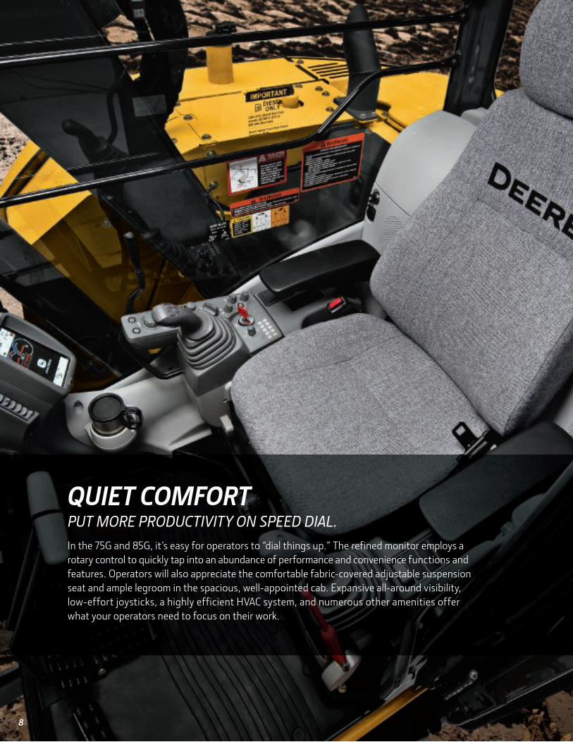
QUIET COMFORT PUT MORE PRODUCTIVITY ON SPEED DIAL.
In the 75G and 85G, it’s easy for operators to “dial things up.” The refined monitor employs a
rotary control to quickly tap into an abundance of performance and convenience functions and
features. Operators will also appreciate the comfortable fabric-covered adjustable suspension
seat and ample legroom in the spacious, well-appointed cab. Expansive all-around visibility,
low-effort joysticks, a highly efficient HVAC system, and numerous other amenities offer
what your operators need to focus on their work.

See clearly now
Wide expanse of front and side glass, narrow front cab posts, large tinted overhead hatch, and numerous mirrors enable all-around visibility.
Take control
Standard lockable control-pattern selector valve allows operators to switch from backhoe- to SAE-style controls with just a twist of the wrist.
At your fingertips
Ergonomically correct short-throw joysticks provide smooth, predictable fingertip control with less movement or effort.
Whatever the weather
Automatic, high-velocity bi-level climate-control system with automotive-style adjustable louvers helps keep the glass clear and the cab comfortable.
In the know
Multi-language LCD monitor and rotary dial provide intuitive access to a wealth of information and functions. Just turn and tap to select work mode, access operating info, check maintenance intervals, source diagnostic codes, adjust cab temperature, and tune the radio.
Keep it down
Spacious cab is noticeably quiet. Silicone-filled mounts effectively isolate noise and vibration.
Light things up
Standard boom/frame lights illuminate the way, to extend your day beyond daylight hours.
Have a seat
We’ve got your back with sculpted mechanical-suspension multi-position mid- and high-back seats.
AUTO BI-LEVELCLIMATE-CONTROL
SYSTEM

10
PROVEN PERFORMERS TAKE IT ON.
Just like you, our 75G and 85G Excavators don’t quit. These
dependable workers deliver rugged reliability, with job-proven
digging structures and hydraulic, electrical, and undercarriage
components. Highly efficient cooling systems keep things running
cool, even in high altitudes or harsh environments. Other durability-
enhancing “extras” include tungsten-carbide-coated wear surfaces
and oil-impregnated bushings. When you know how they’re built,
you’ll see how tough they are.
Stress management
A John Deere feature, three welded bulkheads within the boom resist torsional stress.
Rugged reinforcement
Rigid, reinforced D-channel side frames resist impacts, maximizing cab and component protection.
Coat of arms
Tungsten-carbide coating creates an extremely wear-resistant surface to protect the all-important bucket-to-arm joint.
Tough enough
Box-section track frames, thick-plate single-sheet mainframe, and large swing bearing deliver rock-solid durability. Strong shields deflect material and impacts, protecting the blade cylinder and propel motors.
Fan appeal
Viscous fan continuously adjusts speed as necessary for effective cooling. Helps reduce noise and fuel consumption, too.
Wrap it up
Wear-resistant hoses are routed, secured, and guarded for exceptional durability. Cordura® covering and wire wrapping adds an extra degree of protection to exposed hoses. O-ring face-seal couplers virtually eliminate leaks.
Underneath it all
Large idlers, rollers, and strutted links in the sealed and lubricated undercarriage deliver reliable performance. Optional heavy- duty rubber track pads provide the long-term durability of a steel undercarriage, yet are easy on hard surfaces such as asphalt or concrete.
DURABLED-CHANNELSIDE FRAMES
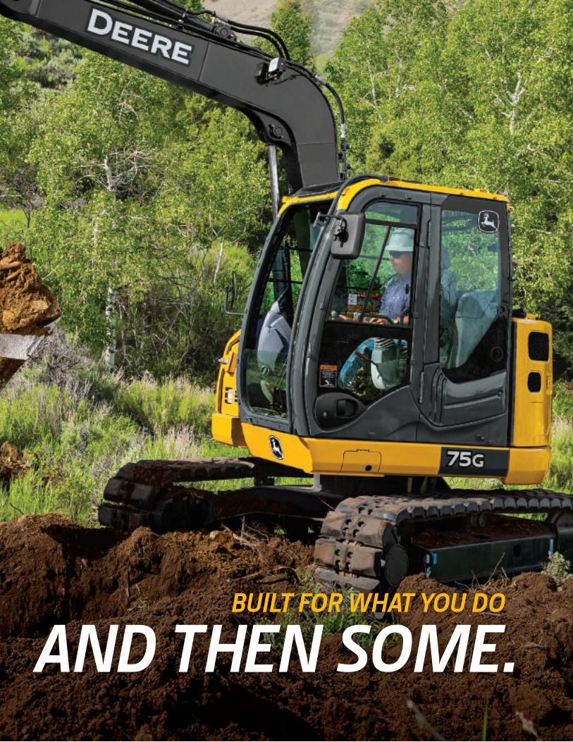
BUILT FOR WHAT YOU DO AND THEN SOME.

12
CUT MAINTENANCE TIMEAND OPERATING COSTS, TOO.
Go for a spin
Vertical spin-on fuel filter and water separator are conveniently located in the right rear compartment for quick, convenient ground-level service access.
It’s all right there
Large hinged doors enable easy access to service items. Left rear compartment houses the battery, engine air filter, fresh-air cab filter, and side-by-side coolers.
Service simplified
Sight gauges and see-through reservoirs allow hydraulic, coolant, and window-washer fluid-level checks at a glance. Lube banks, filters, and service points are grouped for added convenience.
Extended intervals
Large fuel tank and 500- and 5,000-hour engine and hydraulic oil-service intervals decrease downtime for routine maintenance. Oil-impregnated bushings enhance durability and extend grease intervals to 500 hours for the arm-and-boom joint and 100 hours for the bucket joint.

Reliable engine technology
The EPA Final Tier 4 (FT4)/EU Stage IV technology in these excavators is simple, fuel efficient, fully integrated, and fully supported. It employs field-proven cooled exhaust gas recirculation (EGR) for reducing NOX, and a diesel particulate filter (DPF) and diesel oxidation catalyst (DOC) to reduce particulate matter (PM). DPF cleaning happens automatically without impacting machine productivity. Minimum service interval is 3,000 hours and can be done by your John Deere dealer.

14
Engine 75GManufacturer and Model Yanmar 4TNV98CNon-Road Emission Standard EPA Final Tier 4/EU Stage IVNet Power (ISO 9249) 42.4 kW (56.9 hp) at 2,000 rpmCylinders 4Displacement 3.3 L (202 cu. in.)Aspiration NaturalOff-Level Capacity 70% (35 deg.)CoolingVariable-speed fan; viscous clutchPowertrain2-speed propel with automatic shiftMaximum Travel Speed
Low 3.1 km/h (1.9 mph)
High 5.0 km/h (3.1 mph)Drawbar Pull 6650 kgf (14,661 lb.)HydraulicsOpen center, load sensingMain Pumps 3 variable-displacement axial-piston pumps
Maximum Pump Flow 2 x 72 + 56 L/m (2 x 19 + 15 gpm)Pilot Pump 1 gear
Maximum Rated Flow 20 L/m (5.3 gpm)System Relief Pressure 3900 kPa (566 psi)
System Operating PressureImplement Circuits 26 000 kPa (3,771 psi)Travel Circuits 31 400 kPa (4,554 psi)Swing Circuits 25 200 kPa (3,655 psi)
Controls Pilot levers, short stroke, low effort; hydraulic pilot controls with shutoff leverCylindersHeat-treated, chrome-plated, polished cylinder rods; hardened steel (replaceable bushings) pivot pins
Bore Rod Diameter Stroke
Boom (1) 115 mm (4.5 in.) 65 mm (2.6 in.) 885 mm (34.8 in.)Arm (1) 95 mm (3.7 in.) 60 mm (2.4 in.) 900 mm (35.4 in.)Bucket (1) 85 mm (3.3 in.) 55 mm (2.2 in.) 730 mm (28.7 in.)ElectricalBatteries 2 x 12 voltBattery Capacity 2 x 450 CCAAlternator Rating 50 ampWork Lights 2 halogen: 1 mounted on boom and 1 mounted on frameUndercarriageRollers (each side)
Carrier 1Track 5
Shoes (each side) 40Track
Adjustment HydraulicChain Sealed and lubricated
Swing MechanismSwing Speed 10.5 rpmSwing Torque 16 600 Nm (12,244 lb.-ft.)
SPECIFICATIONS

Operating Dimensions
Arm Length 2.12 m (6 ft. 11 in.)Arm Digging Force (ISO) 30.7 kN (6,902 lb.)Bucket Digging Force (ISO) 46.6 kN (10,476 lb.)
A Maximum Reach 6.92 m (22 ft. 8 in.)A| Maximum Reach at Ground Level 6.76 m (22 ft. 2 in.)B Maximum Digging Depth 4.61 m (15 ft. 1 in.)B| Maximum Digging Depth at 2.44-m (8 ft.) Flat Bottom 4.32 m (14 ft. 2 in.)C Maximum Cutting Height 7.61 m (25 ft. 0 in.)D Maximum Dumping Height 5.51 m (18 ft. 1 in.)E Minimum Swing Radius 2.17 m (7 ft. 1 in.)F Maximum Vertical Wall 4.22 m (13 ft. 10 in.)G Tail Swing Radius 1.29 m (4 ft. 3 in.)
Ground Pressure 75G
450-mm (18 in.) Rubber Crawler Pads 39 kPa (5.6 psi)450-mm (18 in.) Continuous Rubber Belt 39 kPa (5.6 psi)450-mm (18 in.) Triple Semi-Grouser Shoes 38 kPa (5.4 psi)600-mm (24 in.) Triple Semi-Grouser Shoes 27 kPa (3.9 psi)Serviceability
Refill Capacities
Fuel Tank 135 L (35.7 gal.)Cooling System 9.7 L (2.6 gal.)Engine Oil with Filter 12.3 L (3.2 gal.)Hydraulic Tank 56 L (15 gal.)Hydraulic System 103 L (27 gal.)Propel Gearbox (each) 1.2 L (1.3 qt.)
Operating Weights
With 0.31-m3 (0.41 cu. yd. ), 762-mm (30 in.), 313-kg (691 lb.) Bucket; 2.12-m (6 ft. 11 in.) Arm; 1305-kg (2,877 lb.) Counterweight; 2470-mm (8 ft. 1 in.) Blade; Full Fuel Tank; and 75-kg (165 lb.) Operator
450-mm (18 in.) Rubber Crawler Pads 8143 kg (17,952 lb.)450-mm (18 in.) Triple Semi-Grouser Shoes 7882 kg (17,377 lb.)600-mm (24 in.) Triple Semi-Grouser Shoes 8265 kg (18,221 lb.)450-mm (18 in.) Continuous Rubber Belt 7898 kg (17,412 lb.)
Optional Components
Undercarriage (with the following)450-mm (18 in.) Rubber Crawler Pads 2903 kg (6,400 lb.)450-mm (18 in.) Continuous Rubber Belt 2867 kg (6,321 lb.)450-mm (18 in.) Triple Semi-Grouser Shoes 2851 kg (6,285 lb.)600-mm (24 in.) Triple Semi-Grouser Shoes 3025 kg (6,669 lb.)
1-Piece Boom (with arm cylinder) 497 kg (1,096 lb.)2.12-m (6 ft. 11 in.) Arm with Bucket Cylinder and Linkage 276 kg (608 lb.)Boom Lift Cylinders (2), Total Weight 178 kg (392 lb.)Counterweight, Standard 1305 kg (2,877 lb.)
CE
NT
ER
LIN
E O
F S
WIN
G
E
D
C
F
G
GROUND LINE
A'
A
B'
B
SPECIFICATIONS

75G
16
Machine Dimensions 75GArm Length 2.12 m (6 ft. 11 in.)
A Overall Length 6.37 m (20 ft. 11 in.)B Overall Height 2.69 m (8 ft. 10 in.)C Undercarriage Width
With 450-mm (18 in.) Shoes 2.32 m (7 ft. 7 in.)With 600-mm (24 in.) Shoes 2.47 m (8 ft. 1 in.)
D Rear-End Length/Swing Radius 1.29 m (4 ft. 3 in.)E Distance Between Idler/Sprocket Centerline 2.29 m (7 ft. 6 in.)F Undercarriage Length 2.92 m (9 ft. 7 in.)G Counterweight Clearance 0.73 m (29 in.)H Cab Height 2.69 m (8 ft. 10 in.)I Ground Clearance 360 mm (14 in.)J Upperstructure Width 2.32 m (7 ft. 7 in.)K Gauge Width 1.87 m (6 ft. 2 in.)L Blade Lift Height 360 mm (14 in.)
Blade Height 480 mm (19 in.)Blade WidthWith 450-mm (18 in.) Shoes 2320 mm (7 ft. 7 in.)With 600-mm (24 in.) Shoes 2470 mm (8 ft. 1 in.)
M Blade Cut Below Grade 300 mm (12 in.)N Blade Lift Angle 27 deg.O Track Width
With 450-mm (18 in.) Shoes 0.45 m (18 in.)With 600-mm (24 in.) Shoes 0.60 m (24 in.)
J
H
O
I
K
C
B
D
G
EF
A
L
M
N
Lift CapacitiesBoldface type indicates hydraulically limited capacities; lightface type indicates stability-limited capacities, in kg (lb.). Ratings are at bucket lift hook, using standard counterweight, situated on firm, level, uniform supporting surface. Total load includes weight of cables, hook, etc. Figures do not exceed 87% of hydraulic capacity
or 75% of weight needed to tip machine. All lift capacities are based on ISO 10567.HORIZONTAL DISTANCE FROM CENTERLINE OF ROTATION
1.5 m (5 ft.) 3.0 m (10 ft.) 4.5 m (15 ft.)LOAD POINT HEIGHT Over Front Over Side Over Front Over Side Over Front Over SideWith 3.72-m (12 ft. 8 in.) boom, 2.12-m (6 ft. 11 in.) arm, 0.28-m3 (0.37 cu. yd.) bucket, 450-mm (18 in.) rubber pads, and 2320-mm (7 ft. 9 in.) blade
4.5 m (15 ft.) 1475 (3,252)
1475 (3,252)
3.0 m (10 ft.) 1834 (4,043)
1834 (4,043)
1613 (3,557)
1613 (3,557)
1.5 m (5 ft.) 2864 (6,313)
2797 (6,167)
1958 (4,317)
1541 (3,397)
Ground Line 3508 (7,734)
2629 (5,797)
2248 (4,956)
1472 (3,246)
–1.5 m (–5 ft.) 3544 (7,813)
3544 (7,813)
3514 (7,746)
2594 (5,718)
2252 (4,964)
1451 (3,199)
–3.0 m (–10 ft.) 5020 (11,068)
5020 (11,068)
2742 (6,044)
2663 (5,870)

75G
Lift Capacities (continued) 75GBoldface type indicates hydraulically limited capacities; lightface type indicates stability-limited capacities, in kg (lb.). Ratings are at bucket lift hook, using standard counterweight, situated on firm, level, uniform supporting surface. Total load includes weight of cables, hook, etc. Figures do not exceed 87% of hydraulic capacity or 75% of weight needed to tip machine. All lift capacities are based on ISO 10567.
HORIZONTAL DISTANCE FROM CENTERLINE OF ROTATION1.5 m (5 ft.) 3.0 m (10 ft.) 4.5 m (15 ft.)
LOAD POINT HEIGHT Over Front Over Side Over Front Over Side Over Front Over SideWith 3.72-m (12 ft. 8 in.) boom, 2.12-m (6 ft. 11 in.) arm, 0.28-m3 (0.37 cu. yd.) bucket, 600-mm (24 in.) shoes, and 2470-mm (8 ft. 1 in.) blade
4.5 m (15 ft.) 1475 (3,252)
1475 (3,252)
3.0 m (10 ft.) 1834 (4,043)
1834 (4,043)
1613 (3,557)
1613 (3,557)
1.5 m (5 ft.) 2864 (6,313)
2841 (6,263)
1958 (4,317)
1566 (3,452)
Ground Line 3508 (7,734)
2673 (5,893)
2248 (4,956)
1497 (3,301)
–1.5 m (–5 ft.) 3544 (7,813)
3544 (7,813)
3514 (7,746)
2637 (5,814)
2252 (4,964)
1476 (3,254)
–3.0 m (–10 ft.) 5020 (11,068)
5020 (11,068)
2742 (6,044)
2707 (5,967)
BucketsA full line of buckets is offered to meet a wide variety of applications. Replaceable cutting edges are available through John Deere Parts. Optional side cutters add 150 mm (6 in.) to bucket widths.
Type Bucket Bucket Width Bucket Capacity Bucket WeightBucket Dig Force (ISO)
Arm Dig Force (ISO) 2.12 m (6 ft. 11 in.) Bucket Tip Radius
Number of Teeth
mm in. m3 cu. yd. kg lb. kN lb. kN lb. mm in.Heavy Duty 610 24 0.24 0.31 268 591 44 9,892 29 6,524 883 34.76 5
762 30 0.31 0.41 313 691 44 9,892 29 6,524 883 34.76 6 914 36 0.39 0.51 358 790 44 9,892 29 6,524 883 34.76 7
Ditching 1219 48 0.49 0.64 330 727 64 14,344 33 7,473 907 35.69 0Bucket Selection Guide*
1.0(1.25)
0.6(0.75)
2,000 2,200 2,600 3,200lb./cu. yd.
kg/m3
BU
CK
ET
SIZ
E m
(cu
. yd
.)3
1,600 3,400
0.2(0.25)
0.4(0.50)
0.8(1.00)
1.2(1.50)
1,200 1,400 1,800 2,400 2,800 3,000 3,600
Wet
Pea
t
Top
soil
Co
al
Cal
iche
Shal
e
Dry
San
d
Dry
Cla
y
Lim
esto
ne
Wet
Ear
th
Wet
Cla
y, G
rani
te
Mo
ist
Sand
Wet
San
d
Wet
San
d, G
rave
l
1300
Contact your John Deere dealer for optimum bucket and attachment selections. These recommendations are for general conditions and average use. Does not include
optional equipment such as thumbs or couplers. Larger buckets may be possible when using light materials, for flat and level operations, less compacted materials,
and volume loading applications such as mass-excavation applications in ideal conditions. Smaller buckets are recommended for adverse conditions such as off-level
applications, rocks, and uneven surfaces. Bucket capacity indicated is SAE heaped.
*
700 800 900 1000 1100 1200 20001400 1500 1600 1700 1800 1900 2100
Deere 2.12-m (6 ft. 11 in.) Arm

18
Engine 85GManufacturer and Model Yanmar 4TNV98C-WHBWNon-Road Emission Standard EPA Final Tier 4/EU Stage IVNet Power (ISO 9249) 42.4 kW (56.9 hp) at 2,000 rpmCylinders 4Displacement 3.3 L (202 cu. in.)Aspiration NaturalOff-Level Capacity 70% (35 deg.)CoolingVariable-speed fan; viscous clutchPowertrain2-speed propel with automatic shiftMaximum Travel Speed
Low 3.1 km/h (1.9 mph)
High 5.0 km/h (3.1 mph)Drawbar Pull 6650 kgf (14,661 lb.)HydraulicsOpen center, load sensingMain Pumps 3 variable-displacement axial-piston pumps
Maximum Pump Flow 2 x 72 + 56 L/m (2 x 19 + 15 gpm)Pilot Pump 1 gear
Maximum Rated Flow 20 L/m (5.3 gpm)System Relief Pressure 3900 kPa (566 psi)
System Operating PressureImplement Circuits 26 000 kPa (3,771 psi)Travel Circuits 31 400 kPa (4,554 psi)Swing Circuits 25 000 kPa (3,626 psi)
Controls Pilot levers, short stroke, low effort; hydraulic pilot controls with shutoff leverCylindersHeat-treated, chrome-plated, polished cylinder rods; hardened steel (replaceable bushings) pivot pins
Bore Rod Diameter Stroke
Boom (1) 115 mm (4.5 in.) 65 mm (2.6 in.) 885 mm (34.8 in.)Arm (1) 95 mm (3.7 in.) 60 mm (2.4 in.) 900 mm (35.4 in.)Bucket (1) 85 mm (3.3 in.) 55 mm (2.2 in.) 730 mm (28.7 in.)ElectricalBatteries 2 x 12 voltBattery Capacity 2 x 450 CCAAlternator Rating 50 ampWork Lights 2 halogen: 1 mounted on boom and 1 mounted on frameUndercarriageRollers (each side)
Carrier 1Track 5
Shoes (each side) 40Track
Adjustment HydraulicChain Sealed and lubricated
Swing MechanismSwing Speed 10.5 rpmSwing Torque 16 600 Nm (12,244 lb.-ft.)Boom Swing
Left 60 deg.Right 60 deg.
SPECIFICATIONS

Ground Pressure 85G
450-mm (18 in.) Rubber Crawler Pads 41.5 kPa (6.0 psi)450-mm (18 in.) Continuous Rubber Belt 41.4 kPa (6.0 psi)450-mm (18 in.) Triple Semi-Grouser Shoes 41.3 kPa (6.0 psi)600-mm (24 in.) Triple Semi-Grouser Shoes 31.7 kPa (4.6 psi)Serviceability
Refill Capacities
Fuel Tank 120 L (31.7 gal.)Cooling System 9.7 L (2.6 gal.)Engine Oil with Filter 12.3 L (3.2 gal.)Hydraulic Tank 56 L (15 gal.)Hydraulic System 103 L (27 gal.)Propel Gearbox (each) 1.2 L (1.3 qt.)
Operating Weights
With 0.31-m3 (0.41 cu. yd. ), 762-mm (30 in.), 313-kg (691 lb.) Bucket; 2.12-m (6 ft. 11 in.) Arm; 1408-kg (3,104 lb.) Counterweight; Full Fuel Tank; and 75-kg (165 lb.) Operator
2220-mm (7 ft. 3 in.) Blade and 450-mm (18 in.) Rubber Crawler Pads
8729 kg (19,244 lb.)
2220-mm (7 ft. 3 in.) Blade and 450-mm (18 in.) Triple Semi-Grouser Shoes
8677 kg (19,130 lb.)
2470-mm (8 ft. 1 in.) blade and 600-mm (24 in.) Triple Semi-Grouser Shoes
8874 kg (19,564 lb.)
2220-mm (7 ft. 3 in.) Blade and 450-mm (18 in.) Continuous Rubber Belt
8701 kg (19,182 lb.)
Optional Components
Undercarriage (with the following)450-mm (18 in.) Rubber Crawler Pads 2871 kg (6,329 lb.)450-mm (18 in.) Continuous Rubber Belt 2843 kg (6,268 lb.)450-mm (18 in.) Triple Semi-Grouser Shoes 2819 kg (6,215 lb.)600-mm (24 in.) Triple Semi-Grouser Shoes 2970 kg (6,548 lb.)
1-Piece Boom (with arm cylinder) 491 kg (1,082 lb.)2.12-m (6 ft. 11 in.) Arm with Bucket Cylinder and Linkage 275 kg (606 lb.)Boom Lift Cylinder 89 kg (196 lb.)0.49-m3 (0.64 cu. yd.), 1219-mm (48 in.) Ditching Bucket 330 kg (728 lb.)Counterweight (standard) 1408 kg (3,104 lb.)
Operating Dimensions
Arm Length 2.12 m (6 ft. 11 in.)Arm Digging Force (ISO) 30.7 kN (6,902 lb.)Bucket Digging Force (ISO) 46.6 kN (10,476 lb.)
A Maximum Reach 7.70 m (25 ft. 3 in.)A| Maximum Reach at Ground Level 7.55 m (24 ft. 9 in.)B Maximum Digging Depth 4.51 m (14 ft. 10 in.)B| Maximum Digging Depth at 2.44-m (8 ft.) Flat Bottom 4.20 m (13 ft. 9 in.)C Maximum Cutting Height 7.14 m (23 ft. 5 in.)D Maximum Dumping Height 5.08 m (16 ft. 8 in.)E Minimum Swing Radius 2.89 m (9 ft. 6 in.)F Maximum Vertical Wall 4.05 m (13 ft. 3 in.)G Tail Swing Radius 1.49 m (4 ft. 11 in.)
CE
NT
ER
LIN
E O
F S
WIN
GE
D
C
F
G
GROUND LINE
A'
A
B'
B
SPECIFICATIONSNS

85G
20
Machine Dimensions 85GArm Length 2.12 m (6 ft. 11 in.)
A Overall Length 6.82 m (22 ft. 5 in.)B Overall Height with 450-mm (18 in.) Rubber
Crawler Pads2.61 m (8 ft. 7 in.)
C Undercarriage WidthWith 450-mm (18 in.) Shoes 2.20 m (7 ft. 3 in.)With 600-mm (24 in.) Shoes 2.35 m (7 ft. 9 in.)
D Rear-End Length/Swing Radius 1.49 m (4 ft. 11 in.)E Distance Between Idler/Sprocket Centerline 2.29 m (7 ft. 6 in.)F Undercarriage Length 2.92 m (9 ft. 7 in.)G Counterweight Clearance 0.72 m (28 in.)H Cab Height 2.53 m (8 ft. 4 in.)I Ground Clearance 360 mm (14 in.)J Upperstructure Width 2.32 m (7 ft. 7 in.)K Gauge Width 1.75 m (5 ft. 9 in.)L Blade Lift Height 340 mm (13 in.)
Blade Height 460 mm (18 in.)Blade WidthWith 450-mm (18 in.) Shoes 2200 mm (7 ft. 3 in.) With 600-mm (24 in.) Shoes 2350 mm (7 ft. 9 in.)
M Blade Cut Below Grade 320 mm (13 in.)N Blade Lift Angle 26 deg.O Track Width
With 450-mm (18 in.) Shoes 0.45 m (18 in.)With 600-mm (24 in.) Shoes 0.60 m (24 in.)
Lift CapacitiesBoldface type indicates hydraulically limited capacities; lightface type indicates stability-limited capacities, in kg (lb.). Ratings are at bucket lift hook, using standard counterweight, situated on firm, level, uniform supporting surface. Total load includes weight of cables, hook, etc. Figures do not exceed 87% of hydraulic capacity
or 75% of weight needed to tip machine. All lift capacities are based on ISO 10567.HORIZONTAL DISTANCE FROM CENTERLINE OF ROTATION
1.5 m (5 ft.) 3.0 m (10 ft.) 4.5 m (15 ft.) 6.0 m (20 ft.)LOAD POINT HEIGHT Over Front Over Side Over Front Over Side Over Front Over Side Over Front Over SideWith 3.67-m (12 ft. 2 in.) boom, 2.12-m (6 ft. 11 in.) arm, 0.28-m3 (0.37 cu. yd.) bucket, 450-mm (18 in.) rubber pads, and 2200-mm (7 ft. 3 in.) blade
4.5 m (15 ft.) 1735 (3,825)
1656 (3,651)
3.0 m (10 ft.) 2044 (4,506)
1597 (3,521)
1809 (3,988)
1022 (2,253)
1.5 m (5 ft.) 2619 (5,773)
1488 (3,280)
1968 (4,339)
986 (2,174)
Ground Line 2577 (5,682)
2445 (5,391)
2992 (6,597)
1403 (3,092)
2069 (4,561)
952 (2,098)
–1.5 m (–5 ft.) 2683 (5,914)
2683 (5,914)
4770 (10,516)
2448 (5,397)
2868 (6,322)
1377 (3,036)
–3.0 m (–10 ft.) 3130 (7,012)
3130 (5,560)
With 3.67-m (12 ft. 2 in.) boom, 2.12-m (6 ft. 11 in.) arm, 0.28-m3 (0.37 cu. yd.) bucket, 600-mm (24 in.) shoes, and 2470-mm (8 ft. 1 in.) blade4.5 m (15 ft.) 1735
(3,825)1679
(3,702)3.0 m (10 ft.) 2044
(4,506)1620
(3,572)1809
(3,988)1038
(2,289)1.5 m (5 ft.) 2619
(5,773)1511
(3,332)1968
(4,339)1002
(2,210)Ground Line 2577
(5,682)2485
(5,479)2992
(6,597)1426
(3,143)2069
(4,561)968
(2,134)–1.5 m (–5 ft.) 2683
(5,914)2683
(5,914)4770
(10,516)2488
(5,485)2868
(6,322)1400
(3,087)–3.0 m (–10 ft.) 3130
(7,012)3130
(5,647)
J
H
O
I
K
C
B
D
G
EF
A
L
M
N

85G
Lift Capacities (continued) 85GBoldface type indicates hydraulically limited capacities; lightface type indicates stability-limited capacities, in kg (lb.). Ratings are at bucket lift hook, using standard counterweight, situated on firm, level, uniform supporting surface. Total load includes weight of cables, hook, etc. Figures do not exceed 87% of hydraulic capacity or 75% of weight needed to tip machine. All lift capacities are based on ISO 10567.
HORIZONTAL DISTANCE FROM CENTERLINE OF ROTATION1.5 m (5 ft.) 3.0 m (10 ft.) 4.5 m (15 ft.) 6.0 m (20 ft.)
LOAD POINT HEIGHT Over Front Over Side Over Front Over Side Over Front Over Side Over Front Over SideWith 3.67-m (12 ft. 2 in.) boom, 2.12-m (6 ft. 11 in.) arm, less bucket, 450-mm (18 in.) continuous rubber belt, and 2200-mm (7 ft. 3 in.) blade
4.5 m (15 ft.) 1728 (3,810)
1579 (3,480)
3.0 m (10 ft.) 2050 (4,520)
1520 (3,350)
1805 (3,980)
971 (2,140)
1.5 m (5 ft.) 2626 (5,790)
1411 (3,110)
1969 (4,340)
934 (2,060)
Ground Line 2595 (5,720)
2309 (5,090)
2994 (6,600)
1329 (2,930)
2068 (4,560)
903 (1,990)
–1.5 m (–5 ft.) 2708 (5,970)
2708 (5,970)
4758 (10,490)
2309 (5,090)
2862 (6,310)
1306 (2,880)
–3.0 m (–10 ft.) 3139 (6,920)
2386 (5,260)
BucketsA full line of buckets is offered to meet a wide variety of applications. Replaceable cutting edges are available through John Deere Parts. Optional side cutters add 150 mm (6 in.) to bucket widths.
Type Bucket Bucket Width Bucket Capacity Bucket WeightBucket Dig Force (ISO)
Arm Dig Force (ISO) 2.12 m (6 ft. 11 in.) Bucket Tip Radius
Number of Teeth
mm in. m3 cu. yd. kg lb. kN lb. kN lb. mm in.Heavy Duty 610 24 0.31 0.40 287 633 54 12,061 32 7,162 1087 42.80 5
762 30 0.41 0.53 333 735 54 12,061 32 7,162 1087 42.80 6 914 36 0.50 0.66 380 837 54 12,061 32 7,162 1087 42.80 7
Ditching 1219 48 0.49 0.64 330 727 64 14,344 33 7,473 907 35.69 0Bucket Selection Guide*
1.0(1.25)
0.6(0.75)
2,000 2,200 2,600 3,200lb./cu. yd.
kg/m3
BU
CK
ET
SIZ
E m
(cu
. yd
.)3
1,600 3,400
0.2(0.25)
0.4(0.50)
0.8(1.00)
1.2(1.50)
1,200 1,400 1,800 2,400 2,800 3,000 3,600
Wet
Pea
t
Top
soil
Co
al
Cal
iche
Shal
e
Dry
San
d
Dry
Cla
y
Lim
esto
ne
Wet
Ear
th
Wet
Cla
y, G
rani
te
Mo
ist
Sand
Wet
San
d
Wet
San
d, G
rave
l
1300
Contact your John Deere dealer for optimum bucket and attachment selections. These recommendations are for general conditions and average use. Does not include
optional equipment such as thumbs or couplers. Larger buckets may be possible when using light materials, for flat and level operations, less compacted materials,
and volume loading applications such as mass-excavation applications in ideal conditions. Smaller buckets are recommended for adverse conditions such as off-level
applications, rocks, and uneven surfaces. Bucket capacity indicated is SAE heaped.
*
700 800 900 1000 1100 1200 20001400 1500 1600 1700 1800 1900 2100
Deere 2.12-m (6 ft. 11 in.) Arm

Net engine power is with standard equipment including air cleaner, exhaust system, alternator, and cooling fan at test conditions specified per ISO 9249.No derating is required up to 3050-m (10,000 ft.) altitude. Specifications and design subject to change without notice. Wherever applicable, specifications are
in accordance with SAE standards. Except where otherwise noted, these specifications are based on units with standard equipment; 0.31-m3 (0.41 cu. yd.),762-mm (30 in.), 313-kg (691 lb.) buckets; 450-mm (18 in.) rubber crawler pad shoes; 2.12-m (6 ft. 11 in.) arms; full fuel tanks; and 75-kg (165 lb.) operators;
a 75G unit with 1305-kg (2,877 lb.) counterweight; and an 85G unit with 1408-kg (3,104 lb.) counterweight.
Key: l Standard s Optional or special See your John Deere dealer for further information.
Additional equipment
JohnDeere.com
08-08-19
75G 85G Engine
l l Auto-idle system
l l Batteries (2 – 12 volt)
l l Coolant recovery tank
l l Single-element air filter
l l Electronic engine control
l l Enclosed fan guard (conforms to SAE J1308)
l l Engine coolant to –37 deg. C (–34 deg. F)
l l Fuel filter with water separator
l l Full-flow oil filter
l l Radiator and oil cooler with dust- protective net
l l Glow-plug start aid
l l 500-hour engine oil-change interval
l l 70% (35 deg.) off-level capacity
l l Isolation mounted
Hydraulic System
l l Reduced-drift valve for boom down, arm in
l l Auxiliary hydraulic valve section
l l Spring-applied, hydraulically released automatic swing brake
l l Auxiliary hydraulic-flow adjustments
through monitor
l l 5,000-hour hydraulic oil-change interval
l l Auxiliary hydraulics
l l Control pattern-change valve
s s Hydraulic filter restriction indicator kit
s s Load-lowering control device
s s Single-pedal propel control
Undercarriage
l l Planetary drive with axial piston motors
l l Propel motor shields
l l Spring-applied, hydraulically released automatic propel brake
l l 2-speed propel with automatic shift
l l Upper carrier roller (1)
l l Sealed and lubricated track chain
l l Undercarriage with blade
s s Triple semi-grouser shoes, 450 mm (18 in.)
s s Triple semi-grouser shoes, 600 mm (24 in.)
75G 85G Undercarriage (continued)
s s Rubber crawler pads, 450 mm (18 in.)
s s Rubber belt, continuous, 450 mm (18 in.)
Upperstructure
l Counterweight, 1305 kg (2,877 lb.)
l Counterweight, 1408 kg (3,104 lb.)
l l Right- and left-hand mirrors
l l Vandal locks with ignition key: Cab door / Engine hood / Fuel cap / Service doors
l l Remote-mounted fuel filters
Front Attachments
l l Centralized lubrication system
l l Dirt seals on all bucket pins
l l Oil-impregnated bushings
l l Reinforced resin thrust plates
l l Tungsten carbide thermal coating on arm-to-bucket joint
l l Arm, 2.12 m (6 ft. 11 in.)
s s Attachment quick-couplers
s s Buckets: Ditching / Heavy duty / Heavy-duty high capacity / Side cutters and teeth
Operator’s Station
l l Meets ISO 12117-2 for ROPS
l l Adjustable independent control positions (seat-to-pedals)
l l AM/FM radio
l l Auto climate control/air conditioner with heater and pressurizer
l l Built-in operator’s manual storage compartment and manual
l l Cell-phone power outlet, 12 volt, 60 watt, 5 amp
l l Coat hook
l l Deluxe cloth suspension seat with adjustable armrests
l l Floor mat
l l Front windshield wiper with inter- mittent speeds
l l Gauges (illuminated): Engine coolant / Fuel
l l Horn, electric
l l Hour meter, electric
l l Hydraulic shutoff lever, all controls
75G 85G Operator’s Station (continued)
l l Hydraulic warm-up control
l l Interior light
l l Large cup holder
l l Machine Information Center (MIC)
l l Mode selectors (illuminated): Power modes (2) / Travel modes (2 with automatic shift) / Work mode (1)
l l Multifunction, color LCD monitor with: Diagnostic capability / Multiple-language capabilities / Maintenance tracking / Clock / System monitoring with alarm features: Auto-idle indicator, engine air cleaner restriction indicator light, engine check, engine coolant temperature indicator light with audible alarm, engine oil pressure indicator light with audible
alarm, low-alternator-charge indicator light, low-fuel indicator light, fault-code alert indicator, fuel-rate display, wiper- mode indicator, work-lights-on indicator, and work-mode indicator
l l Motion alarm with cancel switch (conforms to SAE J994)
l l Auxiliary hydraulic control switches in right console lever
l l SAE 2-lever control pattern
l l Seat belt, 51 mm (2 in.), retractable
l l Tinted glass
l Transparent tinted overhead hatch
l Transparent tinted overhead window
l l Hot/cold beverage compartment
s s Seat belt, 76 mm (3 in.), non-retractable
s s Protection screens for cab front, rear, and side
s Window vandal-protection covers
Electrical
l l 50-amp alternator
l l Blade-type multi-fused circuits
l l Positive-terminal battery covers
Lights
l l Work lights: Halogen / 1 mounted on boom / 1 mounted on frame


