Connecting TCAD To Tapeout A Journal for Circuit Simulation and SPICE Modeling Engineers INSIDE New Philips MOS20 LDMOS Model in SmartSpice .......................................................... 3 Stress Effect Model in BSIM3v3 Model ..................... 5 New SmartLib Library of Models .............................. 7 Calendar of Events ...................................................... 9 Hints, Tips, and Solutions ......................................... 10 BSIM4 Model Verilog-A Implementation BSIM4 Model The Verilog -A hardware description g g language opens many areas to SPICE users in the field of compact models, allowing manufacturers and universities to study or custom- ize the existing models. Berkeley BSIM4 model is developed to explicitly address many issues in modeling sub-0.13 microns CMOS technologies and RF high-speed CMOS circuit simulation. Due to its forefront use, BSIM4 was a good candidate for Verilog-A porting. Continued on page 2 ... Volume 14, Number 1, January 2004 The link with the Verilog-A module is done with MODULE = mosfet parameter assignment. The devices are instanciated in the netlist, for example : YVLGm1 node1 node2 0 0 MOSN W=5U L=1.3U The parameters set on this line become instance parameters. Additional model features like drain/source inversion, N/P MOS type, GMIN convergence improvement and bulk diodes have been implemented. Bulk diodes model can be selected through the model parameter DIOMOD shown in Figure 2. SPICE simulator GMIN option has also been added as a model parameter to improve the convergence properties. The GMIN conductance is taken into account in bulk- drain and bulk-source currents. module mosfet(drain, gate, source, bulk); inout drain, gate, source, bulk; ... parameter MOBMOD=0; // Mobility model selector parameter RDSMOD=0; // Bias-dependent S/D resistance model selector parameter IGCMOD=0; // Gate-to-channel tunneling current model selector parameter IGBMOD=0; // Gate-to-substrate tunneling current model selector parameter CAPMOD=2; // Capacitance model selector parameter RGATEMOD=2;// Gate resistance model selector parameter RBODYMOD=0;// Substrate resistance network model selector parameter DIOMOD=1; // Source/drain junction diode IV model selctor parameter TEMPMOD=0; // Temperature mode selector parameter GEOMOD=0; // Geometry-dependent parasitics model selector parameter RGEOMOD=0; // S/D diffusion resistance and contact model selector parameter PERMOD=1; // Source/Drain perimeter model selector Figure 1. The Silvaco Verilog-A porting is based on the BSIM4 version 3.0 released on May, 9th 2003. The version 2.6.0.R of SmartSpice Verilog-A interface has been used. Verilog-A Porting Silvaco BSIM4 Verilog-A implementation includes all the major physical effects and associated parameters of the original Berkeley version 4.3.0: short/narrow channel effects on threshold voltage, non-uniform doping effects, mobility reduction due to vertical field. All the equations and related parameters have been implemented in a Verilog-A module. The result is a 4,400 lines Verilog-A module. As in Berkeley code, physical effects model selectors are accessible in the Verilog-A module with the parameters shown in Figure 1. These model parameters are accessible in the SmartSpice netlist in the Verilog-A module model card: .MODEL MOSN VLG MODULE = mosfet TYPE = 1 TNOM = 27 + MOBMOD = 0 + RDSMOD = 0 + IGCMOD = 0 + IGBMOD = 0 ...
Transcript
January 2004 Page 1 The Simulation Standard
Connecting TCAD To Tapeout A Journal for Circuit Simulation and SPICE Modeling Engineers
INSIDE
New Philips MOS20 LDMOS Model in SmartSpice.......................................................... 3Stress Effect Model in BSIM3v3 Model ..................... 5New SmartLib Library of Models .............................. 7Calendar of Events...................................................... 9Hints, Tips, and Solutions .........................................10
BSIM4 Model Verilog-A Implementation
BSIM4 ModelThe Verilog-A hardware description The Verilog-A hardware description The Veriloglanguage opens many areas to SPICE users in the fi eld of compact models, allowing manufacturers and universities to study or custom-ize the existing models.
Berkeley BSIM4 model is developed to explicitly address many issues in modeling sub-0.13 microns CMOS technologies and RF high-speed CMOS circuit simulation. Due to its forefront use, BSIM4 was a good candidate for Verilog-A porting.
Continued on page 2 ...
Volume 14, Number 1, January 2004
The link with the Verilog-A module is done with MODULE = mosfet parameter assignment. The devices are instanciated in the netlist, for example :
YVLGm1 node1 node2 0 0 MOSN W=5U L=1.3U
The parameters set on this line become instance parameters.
Additional model features like drain/source inversion, N/P MOS type, GMIN convergence improvement and bulk diodes have been implemented. Bulk diodes model can be selected through the model parameter DIOMOD shown in Figure 2.
SPICE simulator GMIN option has also been added as a model parameter to improve the convergence properties. The GMIN conductance is taken into account in bulk-drain and bulk-source currents.
module mosfet(drain, gate, source, bulk);
inout drain, gate, source, bulk;
...
parameter MOBMOD=0; // Mobility model selector
parameter RDSMOD=0; // Bias-dependent S/D resistance model selector
parameter IGCMOD=0; // Gate-to-channel tunneling current model selector
parameter IGBMOD=0; // Gate-to-substrate tunneling current model selector
parameter CAPMOD=2; // Capacitance model selector
parameter RGATEMOD=2;// Gate resistance model selector
parameter RBODYMOD=0;// Substrate resistance network model selector
parameter DIOMOD=1; // Source/drain junction diode IV model selctor
parameter TEMPMOD=0; // Temperature mode selector
parameter GEOMOD=0; // Geometry-dependent parasitics model selector
parameter RGEOMOD=0; // S/D diffusion resistance and contact model selector
parameter PERMOD=1; // Source/Drain perimeter model selector
Figure 1.
The Silvaco Verilog-A porting is based on the BSIM4 version 3.0 released on May, 9th 2003. The version 2.6.0.R of SmartSpice Verilog-A interface has been used.
Verilog-A PortingSilvaco BSIM4 Verilog-A implementation includes all the major physical effects and associated parameters of the original Berkeley version 4.3.0: short/narrow channel effects on threshold voltage, non-uniform doping effects, mobility reduction due to vertical fi eld. All the equations and related parameters have been implemented in a Verilog-A module. The result is a 4,400 lines Verilog-A module.
As in Berkeley code, physical effects model selectors are accessible in the Verilog-A module with the parameters shown in Figure 1.
These model parameters are accessible in the SmartSpice netlist in the Verilog-A module model card:
The Simulation Standard Page 2 January 2004 January 2004 Page 3 The Simulation Standard
Bulk diode currents contribution is added with <+ operator :
I(drainb, drainp) <+ TYPE * cbd;
N/P MOS type is accounted for with TYPE model parameter.
Model ConvergenceLimitation functionalities have been enabled to help the model to converge with large circuits simulation. max-delta is a voltage nature attribute which has been added recently in the SmartSpice Verilog-A interface. This new feature allows to limit the per-iteration voltage change and is disabled by default.
For using voltage limitation, one must set in Verilog-A fi le:
‘defi ne VOLTAGE_MAXDELTA <value>
‘include “discipline.h”
<value> is the greatest voltage change allowed between 2 consecutive Newton-Raphson iterations. The preprocessor directive ‘defi ne VOLTAGE_MAXDELTA <value> is a shortcut: it overrides the maxdelta default voltage nature attri-bute and must be set before including discipline.h fi le.
BSIM4 SmartSpice internal model has been successfully replaced by the Verilog-A model in the simulation of a 72-devices two-bit MOSFET adder, as shown in the output display Figure 3.
The results fi t the simulation with SmartSpice internal model level=14. In AC analysis, the model has been vali-dated using an operational amplifi er benchmark fi le supplied by Berkeley University team.
Figure 3. Verilog-A BSIM4.3.0 model based two-bit MOSFET adder.
Figure 4. AC analysis of an operational amplifi er with BSIM4 Verilog-A model.
ConclusionBerkeley BSIM4.3.0 model has been successfully imple-mented in Verilog-A HDL at SILVACO. The voltage limitation feature recently implemented in Verilog-A in-terface improves convergence signifi cantly when simu-lating large circuits, with an acceptable simulation time. The Verilog-A model is freely available on SILVACO website (http://www.silvaco.com).
The Simulation Standard Page 2 January 2004 January 2004 Page 3 The Simulation Standard
Introduction
Philips MOS20 was released in January 2004. Its purpose is to provide a high-voltage compact model to describe both operation of the channel region and drift region under the thin gate oxide. It can be used as a replacement for the macro-model composed of MOS9 and MOS30 to describe Lateral or Vertical Double-diffused MOS (LDMOS or VDMOS) or Extended-Drain MOS devices (EPMOS).
A Compact Model to Replace Two Macro-Models
Before MOS20 was released, simulating LDMOS devices re-quired the use of macro-models. To do this, SmartSpice provided the following models: MOS9, MOS30 and MOS40.
One was used to achieve channel region simulation (MOS9) and another was required to account for the drift region (MOS30 or MOS40). Both were assembled at the netlist level, for example in a subcircuit.
MOS20 accounts for both regions, and above all inter-nally computes the voltage at the transition between channel and drift regions. This improvement is very im-portant with regard to convergence. It does not require any external node to link two models together, and this particular voltage is available to model equations since it is internally computed.
The only case when associating MOS20 and MOS40 is still necessary is when very high voltages devices are simulated. In this case, a macro model will help account-ing for the drift region under the thick fi eld oxide.
MOS20 Takes Advantages of all Philips ModelsThe model is based on all the best achievements in compact models. Model core has been derived from the SOI-LDMOS model from University of Southampton.
MOS20 equations are based on surface potentials. With this technique, it provides an accurate description of all operating regimes. Only one equation is computed for all regimes, ensuring that no discontinuity appears, and no smoothing function is used. The equations implemented are based on MOS11 equations. Surface potentials are calculated using an approximation of Poisson equation, in order to get explicit expression of surface potential with regard to node voltages.
This way, MOS20 benefi ts from all the improvements and experience acquired with those models.
New Philips MOS20 LDMOS Model in SmartSpice
Figure 1. Macro-model using MOS9 and MOS30.
Figure 2. The region under the thin gate oxide of LDMOS device (n-channel).
In addition to these core equations, MOS20 also accounts for :
• Mobility reduction
• Velocity saturation
• Drain-Induced Barrier Lowering (DIBL)
• Static feedback
• Channel length modulation
• Weak avalanche current
The Simulation Standard Page 4 January 2004 January 2004 Page 5 The Simulation Standard
Silvaco ImplementationMOS20 implementation in SmartSpice takes advantages of both Philips’ original equations, and SmartSpice com-mon MOSFET features such as :
• Transient Noise analysis using Philips detailed Transient Noise analysis using Philips detailed Tnoise model
• RF analyses with SmartSpiceRF
• Speed improvements : VZERO and BYPASS options, parallel architectures
• Convergence control and user-friendly hints
• Out-of-bound guards, both for parameters and internal values
• Extrinsic elements : bulk diodes, Source/Drain resistances
All these features allow the user to make the most of MOS20 model.
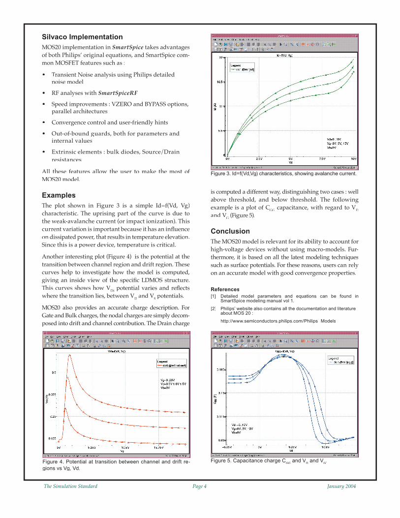
ExamplesThe plot shown in Figure 3 is a simple Id=f(Vd, Vg) characteristic. The uprising part of the curve is due to the weak-avalanche current (or impact ionization). This current variation is important because it has an infl uence on dissipated power, that results in temperature elevation. Since this is a power device, temperature is critical.
Another interesting plot (Figure 4) is the potential at the transition between channel region and drift region. These curves help to investigate how the model is computed, giving an inside view of the specifi c LDMOS structure. This curves shows how VDi potential varies and refl ects where the transition lies, between VD and VS potentials.
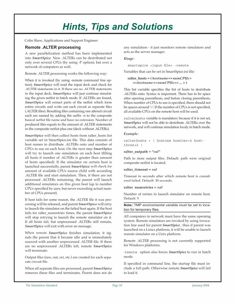
MOS20 also provides an accurate charge description. For Gate and Bulk charges, the nodal charges are simply decom-posed into drift and channel contribution. The Drain charge
is computed a different way, distinguishing two cases : well above threshold, and below threshold. The following example is a plot of CGG capacitance, with regard to VDand VGand VGand V (Figure 5).
ConclusionThe MOS20 model is relevant for its ability to account for high-voltage devices without using macro-models. Fur-thermore, it is based on all the latest modeling techniques such as surface potentials. For these reasons, users can rely on an accurate model with good convergence properties.
References[1] Detailed model parameters and equations can be found in
SmartSpice modeling manual vol 1.
[2] Philips’ website also contains all the documentation and literature about MOS 20 :
G.Figure 4. Potential at transition between channel and drift re-
gions vs Vg, Vd.
The Simulation Standard Page 4 January 2004 January 2004 Page 5 The Simulation Standard
Stress Effect Model in BSIM3v3 Model
Stress effect models are now implemented in major models such as BSIM4 or HiSIM. The need for evermore accurate models with a strong relation to technology is accute. Since BSIM3v3 is still a widely-used model and has not been totally replaced by its successor, an improvement was made to the model in SmartSpice to fulfi ll customers need for stress effect equations.
BackgroundThe stress effect became important for simulation because of more and more shrinking processes. The smaller devices now require effi cient isolation techniques. One of them is Shallow Trench Isolation (STI), mainly used with strain channel materials.
Shallow Trench Isolation is used to replace LOCOS, as shown on the schematic in Figure 1.
This particular process induces a mechanical stress on the device structure. Because of this behavior, device performance is related to the dimension of the active area, as well as the location of the device.
It has been shown that :
• Stress has an infl uence on mobility• Saturation velocity is also modifi ed• Dopant diffusion during processing is modifi ed, lead-
ing to different doping profi les. This implies a threshold voltage shift as well as changes in second-order effect such as Drain-Induced Barrier Lowering (DIBL) and body effect
Berkeley University considered that the effect of stress is due to two main mechanisms: mobility variation in-duced by changes in the band structure, and infl uence on threshold voltage because of different doping profi les as explained above.
Both of these mechanisms have the same dependence on 1/L1/L1/ OD (invert of the Length of Oxide Defi nition), but show a different trend with regard to width and length of the device.
ImplementationWhen the effect is enabled, the following model elements are modifi ed :
The approach used is to tune model parameters values to ac-count for the Stress Effect : it is a phenomenological model.
The Stress Effect was initially developed by Berkeley University in the BSIM4 model. It was improved with new equations along the offi cial releases of the model. Silvaco implementation (both in BSIM3v3 and BSIM4) provides all of these implementations, using a dedicated selector: STIMOD.
In SmartSpice, the user can select among four equations sets:SmartSpice, the user can select among four equations sets:SmartSpice
• STIMOD = 0 : No stress effect• STIMOD = 1: Berkeley model, -version• STIMOD = 2: TSMC model for irregular devices• STIMOD = 3: Berkeley model for multi-fi nger devices
Enabling the Stress Effect model does not imply a longer sim-ulation time, since expressions do not depend on voltages. It is computed only once before running the simulation.
Berkeley β-version model (STIMOD=1)Since the implementation was greatly changed between BSIM4v3.0-β and BSIM4v3.0, Silvaco chose to keep both implementations. The mobility U0(T)and VSAT(T) carrier velocity are computed using the following equations:
Figure 1. Process cross-section showing showing stress regions.
The Simulation Standard Page 6 January 2004 January 2004 Page 7 The Simulation Standard
Berkeley Model for Multi-Finger Devices
This model is the one released by Berkeley in the fi nal BSIM4v3.0 version. Parameters are used to compute the intermediate length LOD (Length of Oxide Defi nition).
Then equations shown in Figure 4 are used.
ConclusionThe Stress Effect model was fi rst tested and improved in the BSIM4 model. Now that it is fully validated, it is also available in BSIM3v3 with the same selectable implementations. This will open new opportunities to customers that still use BSIM3v3 as standard.
TSMC Model for Irregular Devices (STIMOD=2)This model is suitable when there is only one fi nger. Parameters are used to describe square elements of the oxide layer geometry (Figure 2).
The equations used to compute the stress effect are the same as the ones when STIMOD=3, but with different intermediate geometry defi nitions:
Figure 2. Layout dimensions for stress calculation STIMOD=2. Figure 3. Berkley model diagram.
Figure 4. Parameter value modifi cation due to stress effects.
The Simulation Standard Page 6 January 2004 January 2004 Page 7 The Simulation Standard
OverviewIn all previous versions of SmartSpice the model code (BSIM, diode etc.) was included in the one executable (SmartSpice ). This means any updates to the model code would take a while to reach the customer because of the full SPICE functionality checks required before releasing a new SmartSpice version. We have therefore separated the SmartSpice core from the modeling code to eliminate this delay and dependency. Now the new model release time has been reduced by having a separate library that the customer can download from the web and include into the SmartSpice program through the use of these described new functions. All previous SmartSpice func-tionality is maintained as before. This new confi guration is only of interest to customer who wish to explore model changes in more depth.
The -slinstall OptionThe “-slinstall” option moves libraries from a download directory to the installation directory.
Example 1smartspice -slinstall mydir 0.2.0.R
where mydir is the directory of the libraries that have to be installed, and 0.2.0.R is the version number of the SmartLib library it belongs to.
This command will inspect the fi les that lay in the mydir directory. SmartSpice moves each fi le to the installation directory if it can be used as a library, and there is no fi le with the same name. This insures that the fi le installed will work correctly, and that an installed fi le cannot be lost while adding a new one.
To use this option, you must have the rights to modify the installation. Ask to your system Administrator if you are allowed such rights.
How to Use the -slinstall Option
Example 1The situation: I’ve downloaded the Solaris library libSGP_1_0_5_R.so.tar which is in a PUB directory from my home.
At this point, you need to untar the fi le. Move it to the PUB directory:
cd ~/PUB tar -xvf libSGP_1_0_5_R.so.tar
Now you must have the libSGP_1_0_5_R.so in the directory:
smartspice -slinstall . 1.0.0.R
SmartSpice indicates that libSGP_1_0_5_R.so.tar cannot be loaded so it won’t be installed. It also indicates that libSGP_1_0_5_R.so has been copied, and that the installa-tion has been successful.
Example 2The situation: I’ve downloaded the full set of Windows
libraries for SmartSpice 1.1.0.R, and they are in the C:\tmp folder.
Use a Zip de-compactor to get the dll fi les. If you can de-lete the zip fi les it will make the following simpler.
In the Start Menu click on Run. When the window ap-pears, type the following command:
smartspice -slinstall c:\tmp 1.1.0.R
A window opens and indicates that the folder has been created, and that each dll is being copied in the installa-tion folder.
The -sllist OptionThe list option lets you have a look at the installed libraries for a given SmartLib version.
Example 1
smartspice -sllist 0.2.0.R
where 0.2.0.R is the version number of the SmartLib you want to inspect.
This command indicates the interface version number of each fi le in the installation directory, if it is a compatible library, and if the lib can be used or even loaded. It also can be used to confi rm if the installation procedure succeeded.
The -slremove OptionThe remove option removes the older version of the SmartLib .
Example 1smartspice -slremove 0.2.0.R
where 0.2.0.R is the SmartLib you want to erase.
To use this option, you must have the rights to modify the installation. Ask to your system Administrator if you are allowed such rights.
Warning : Once a SmartLib has been removed it cannot be used again.
The -slsmartlibconf OptionThis option updates the confi guration fi le, so that SmartSpice will use the newer libraries.
Example 1smartspice -slsmartlibconf 0.2.0.R
where 0.2.0.R is the version number of the SmartLib you want to use.
SmartSpice inspects the fi les in the SmartLib installation directory. It chooses the valid fi les with the higher version number to update the confi guration fi le.
New SmartLIb Library of Models
The Simulation Standard Page 8 January 2004 January 2004 Page 9 The Simulation Standard
How to Use the -slsmartlibconf Option
Example 1I’ve just installed my Solaris library libSGP_1_0_5_R.so, and I want SmartSpice to use this library.
Just type:
smartspice -slsmartlibconf 1.0.0.R
and insure you have a .SmartSpice.conf fi le in your home directory:
mv ~/.SmartSpice.conf SmartSpice.conf.old
Example 2I’ve just downloaded and installed the full set of libraries from SmartLib 1.1.0.R. How do I make SmartSpice use it?
In the Start Menu click Run, and then type:
smartspice -slsmartlibconf 1.1.0.R
How to Install a Downloaded Library• Create a download directory in your home directory:
cd $HOME mkdir download
• Using your web browser, go to the Silvaco Resource Centre Web site and download the library into the folder you have just created.
• Prepare the library to be installed:
cd $HOME/download tar -xvf *.tar
• Install the library: cd $HOME smartspice -slinstall download 1.0.0.R
• Verify that the library has been installed and is in the list: smartspice -sllist 1.0.0.R
• Make the Library Active: smartspice -slsmartlibconf 1.0.0.R
Table 1. SmartLib Models and Corresponding Shared libraries.
Typegroup Technology Internal name Info Level Lib namenpn BJT BJT Bipolar Junction Transistor 1, 2 libSGPpnp VBIC VBIC Bipolar Junction Transistor 5 libVBIClpnp HICUM HICUM Bipolar Junction Transistor 6 libHICUM PBJT Mextram BJT (Philips) 503 libMEXTRAM MODELLA Philips TPL500 Bipolar Transistor 500 linMODELLA HBT Hetero-Junction Bipolar Transistor 20 libHBTnmos SOI BSIM31SOI Berkeley SOI MOSFET model version 1 (level 25) 25 libBSIM3SOIv1pmos BSIM3SOI2DD Berkeley SOI MOSFET model version 2 (level 27) 27 libBSIM3SOIv2_DDntft BSIM3SOI2FD Berkeley SOI MOSFET model version 2 (level 26) 26 libBSIM3SOIv2_FDptft BSIM3SOI2PD Berkeley SOI MOSFET model version 2 (level 29) 29 libBSIM3SOIv2_PD BSIM3SOI3 Berkeley SOI MOSFET model version 3 (level 33) 33 libBSIM3SOIv3 UFS University of Florida SOI Model (level 21) 21 libUFS LETISOI CEA/LETI SOI MOSFET model 32 libLETISOI
TFT TFT MOS fi eld-effect transistor 15 libLeroux PTFT PolySi TFT model 16 libBerkeleyTFT MOS15 MOS15 TFT Model 35 libRPIaSi MOS16 RPI Poly-Si TFT Model 36 libRPIpolySi
MOSFET MOS123 MOS fi eld-effect transistor 1, 2, 3 libMOSlevel123 BSIM1 Berkeley Short Channel IGFET Model 4, 13 libBSIM1 BSIM3 Berkeley Short Channel IGFET Model ) 81 libBSIM3 Version-3 (level 81)
Berkeley Short Channel IGFET Model )Version-3 (level 81)Berkeley Short Channel IGFET Model )
BSIM3v3 Berkeley Short Channel IGFET Model 8, 49, 53 libBSIM3v3 Version-3 (level 8, 49, 53)
Berkeley Short Channel IGFET Model Version-3 (level 8, 49, 53)Berkeley Short Channel IGFET Model
BSIM3M Modifi ed Berkeley Short Channel 7, 10, 47 libBSIM3v3 IGFET Model Version 3 (level 7,10,47)
Modifi ed Berkeley Short Channel IGFET Model Version 3 (level 7,10,47)Modifi ed Berkeley Short Channel
January12 DesignCon - Santa Clara, CA3 DesignCon - Santa Clara, CA4 DesignCon - Santa Clara, CA5 DesignCon - Santa Clara, CA678910111213141516 DATE - Paris, France17 DATE - Paris, France18 DATE - Paris, France19 DATE - Paris, France20 DATE - Paris, France212223242526272829
February B u l l e t i n B o a r d
PolarFab Delivers Silvaco Process Design Kits for PBC4
BiCMOS/DMOS Process
PolarFab, a U.S.-based pure-play semiconductor foundry, and Silvaco announced the availability of process design kits (PDKs) for PolarFab’s premier process for power manage-ment applications. The PDK sup-ports a complete analog and mixed-signal design fl ow with Silvaco circuit simulation and custom IC CAD tools. This process design kit includes parameterized cells for all of the fi fty active and passive compo-nents. Silvaco was able to complete a comprehensive PDK in a fraction of the time it takes to develop PDKs for other design tool fl ows.”
See Silvaco at EDSFair2004 in Yokohama Japan
Electronic Design and Solution Fair 2004 EDSFair assembles specialized information on advanced device technologies, such as EDA, ASICs, FPGA/PLDs IP re-usage, embedded software and design services. Also featured are the latest trends and targets for further development of electronics technologies
The Simulation Standard, circulation 18,000 Vol. 14, No. 1, January 2004 is copyrighted by Silvaco International. If you, or someone you know wants a subscription to this free publication, please call (408) 567-1000 (USA), (44) (1483) 401-800 (UK), (81)(45) 820-3000 (Japan), or your nearest Silvaco distributor.
If you would like more information or to register for one of our our workshops, please check our web site at http://www.silvaco.com
The Simulation Standard Page 10 January 2004 January 2004 Page 11 The Simulation Standard
Remote .ALTER processingA new parallelization method has been implemented into SmartSpice. Now .ALTERs can be destributed not only over several CPUs (by using -P option), but over a network of computers as well.
Remote .ALTER processing works the following way:
When it is invoked (by using -remote command line op-tion), SmartSpice will read the input deck and check for .ALTER statements in it. If there are no .ALTER statements in the input deck, SmartSpice will just continue simulat-ing the given netlist in batch mode. If .ALTERs are found, SmartSpice will extract parts of the netlist which form entire circuits and write out each circuit as separate fi les (.ALTER fi les). Resulting fi les containing one altered circuit each are named by adding the suffi x -n to the composite basical netlist fi le name and have no extension. Number of produced fi les equals to the amount of .ALTER statements in the composite netlist plus one (deck without .ALTERs).
SmartSpice will then collect hosts from ralter_hosts list variable set in SmartSpice.ini fi le. This data consists of host names to distribute .ALTERs onto and number of CPUs to use on each host. On the next step SmartSpice will try to launch one simulation on each host (fi lling all hosts if number of .ALTERs is greater than amount of hosts specifi ed). If the simulator on certain host is launched successfully, parent SmartSpice will check for amount of available CPUs source child with according .ALTER fi le and start simulation. Then, if there are not processed .ALTERs remaining, the parent will launch additional simulators on this given host (up to number CPUs specifi ed by user, but never exceeding actual num-ber of CPUs present).
If host fails for some reason, the .ALTER fi le it was pro-cessing will be released, and parent SmartSpice will retry to launch the simulator on the failed host again. If the host fails for ralter_numretries times, the parent SmartSpice will stop retrying to launch the remote simulator on it. If all hosts fail, but unprocessed .ALTERs still remain, SmartSpice will exit with error an message.
When remote SmartSpice fi nishes simulation, it sig-nals the parent that it became idle and is immediately sourced with another unprocessed .ALTER fi le. If there are no unprocessed .ALTERs left, remote SmartSpice will terminate.
Output fi les (raw, out, err, etc.) are created for each sepa-rate circuit fi le.
When all separate fi les are processed, parent SmartSpice removes these fi les and terminates. Parent does not do
any simulation - it just monitors remote simulators and acts as the server manager.
Usage :
smartspice <input-fi le> -remote
Variables that can be set in SmartSpice.ini fi le:
This list variable specifi es the list of hosts to destribute .ALTERs onto. Syntax is important. There has to be space after opening parenthesis, and before closing parenthesis. When number of CPUs to use is specifi ed, there should not be spaces around ‘=’. If the number of CPUs is not specifi ed, all available CPUs on the remote host will be used.
ralter_hosts variable is mandatory because if it is not set, SmartSpice will not be able to destribute .ALTERs over the network, and will continue simulation localy in batch mode.
Example :
ralter_hosts = ( hostone hosttwo=4 host-three=2 )
ralter_outpath = “val”
Path to store output fi les. Default: path were original composite netlist is located.
ralter_timeout = val
Timeout in seconds after which remote host is consid-ered failed. Default: 30 seconds.
ralter_numretries = val
Number of retries to launch simulator on remote host. Default: 5
Note: TMP environmental variable must be set to loca-tion for temporary fi les.
All computers in network must have the same operatng system. Remote simulators are invoked by using invoca-tion line used for parent SmartSpice , thus if parent was launched on a Linux platform, it will be unable to launch remote simulator on a Unix platform.
Remote .ALTER processing is not currently supported for Windows platforms.
-remote option also forces SmartSpice to run in batch mode.
If specifi ed in command line, the startup fi le must in-clude a full path. Otherwise remote SmartSpice will fail to load it.
Hints, Tips and SolutionsColin Shaw, Applications and Support Engineer
The Simulation Standard Page 10 January 2004 January 2004 Page 11 The Simulation Standard
Call for QuestionsIf you have hints, tips, solutions or questions to contribute,
please contact our Applications and Support Department Phone: (408) 567-1000 Fax: (408) 496-6080
Hints, Tips and Solutions ArchiveCheck our our Web Page to see more details of this example
plus an archive of previous Hints, Tips, and Solutions
www.silvaco.com
.OVERSHOOT Statement Improved
.OVERSHOOT statement has been improved. In previous versions of SmartSpice this statement allowed the user to check all nodes on every timepoint during the simulation, and report nodes with voltages exceeding limits specifi ed by vmin and vmax. Report contained node names along with time points whenever a violation occurs.
Now .OVERSHOOT functionality has been enhanced making it more powerfull and more convinient to use. It is now possible to specify not only voltage thresholds, but also minimum spike duration to detect, and nodes list that have to be excluded from checking.
Output format has also changed. Previous report con-tained node names and timepoints when a spike oc-cured, and was sorted by timepoints. Now report is sort-ed by nodes. If spike occured on any certain node, fi rst there’s a line stating that v(x) > x) > x vmax or v(x) < x) < x vmin and then is followed by listing of spikes detected. This list contains spike start time, spike end time, spike duration and peak voltage (maximum voltage in case of >vmax spike or minimum voltage in <vmin spike case).
It is now possible to specify more than one statement for single analysis. But like in previous versions, the only analysis supported is TRAN.
Syntax
.OVERSHOOT fi lename=”val” <vmin=val> <vmax=val> <duration=val>
fi lename: The name of the fi le where overshoot informa-tion is saved. This fi le contains comment lines that identify the circuit name and type, the type and date of the simula-tion, specifi ed params and report on detected spikes.
vmin=val, vmax=val: These value specify voltage limits. At least one of them has to be present.
duration=val: Specifi es minimum duration of spike to detect. If omitted, SmartSpice will detect spikes of any duration.
excludenodes: List of nodes to exclude from checking. Wildcards can be used. If not specifi ed, SmartSpice will check all nodes.
Example :
.OVERSHOOT fi lename=”o.ost” vmin=-0.2 vmax=0.9
duration=1p + excludenodes=”0 va* x3.*”
New RNOISE Parameter for ResistorA new optional device parameter, specifi ed resistance value for noise analysis (which can be different from DC/TRAN or AC analysis resistance values) was added for linear resistor specifi cation:
RNOISE|NOISE=val: Resistance for noise simulation. Default is AC or R value.
Example :
R 3 7 R=0.001 AC=1e10 RNOISE=0.001
In this example resistor R5, connected between nodes 3 and 7, for DC and Transient Analysis has a resis-tance value R=0.001 Ohm, Noise Analysis resistance is Rnoise=0.001Ohm, and AC analysis resistance is AC=1e10 Ohm.
Multiple nested .DC, .AC, .TRAN sweepNow, SmartSpice allows the user to use the multiple nested parametric sweep for .DC, .AC, .TRAN analyses.
The multiple nested parametric sweep works the follow-ing way:
At fi rst SmartSpice saves the current amounts and makes the start initialization of the all sweep variables.
After that, SmartSpice performs the specifi ed analysis, changing settings for the fi rst sweep variable. When the loop of the fi rst sweep variable is fi nished SmartSpice makes the start initialization for the fi rst sweep variable, and next step for the second sweep variable. SmartSpice repeat the above mentioned actions until the loop of the second sweep variable will not be fi nished.
The multiple sweep uses nested loops like:
for (, ,)
for (, ,)
for(, ,)
Finally, SmartSpice restores the amounts of sweep vari-ables.
The multiple nested parametric sweep is an extension for the standard sweep ideology. Sweep blocks have the same syntax and must be started with keyword “SWEEP”.