SURF RAKE® INSTRUCTION & PARTS MANUAL MODEL 600HD _____________ MACHINE SERIAL NUMBER CATALOG 600HD 1006 H. Barber & Sons, Inc. 15 Raytkwich Dr. Naugatuck, CT 06770 USA TEL: 203.729.9000 FAX: 203 729.4000 WEBSITE: www.hbarber.com
Transcript
SURF RAKE®
INSTRUCTION & PARTSMANUAL
MODEL 600HD
_____________MACHINE SERIAL NUMBER
CATALOG 600HD 1006
H. Barber & Sons, Inc. 15 Raytkwich Dr. Naugatuck, CT 06770 USA TEL: 203.729.9000 FAX: 203 729.4000 WEBSITE: www.hbarber.com
IMPORTANT SAFETY INFORMATIONFOR SURF RAKE® OWNERS, OPERATOR EMPLOYERS
AND OPERATORS
1. Do not allow individuals to operate the Surf Rake® without first receiving personalized trainingand ensuring that they have read this manual.
2. Before each operation of the Surf Rake®, make a careful visual inspection of the machine. Donot operate if you observe damaged or missing parts, missing guards, excessive wear orunusual noise or vibration during startup.
3. Never allow a bystander to approach the operating Surf Rake®, whether or not it is movingforward. Stop the Surf Rake® unless that individual is qualified and is present for the specificpurpose of assisting in the operation, maintenance or repair of the Surf Rake®.
4. Never allow a bystander to approach the operating Surf Rake® and stand under or near thehopper while it is being raised or lowered.
5. Do not attempt to clear large obstacles from the path of the Surf Rake® by pushing them withthe Tractor or the Surf Rake®. Stop the Surf Rake®, turn it off and manually remove obstacles.Seek assistance if you cannot do so alone.
6. Never attempt to clear a jam by placing hands or any part of the body into or near the machinerywhich has not been completely shut down. A jammed conveyor component can immediatelyjump into motion and cause serious injury to hands or other body parts in immediate contact withthe components if the system is under hydraulic pressure.
7. Stand clear of the Surf Rake® when it is being set down on its foot stands or jack stand, toprevent injury.
8. Follow OSHA regulations regarding hydraulic fluid, fire safety, guarding and if applicable, lock-out/tag/out procedures.
9. Before conducting any repair or maintenance on the Surf Rake®, insure that the hydraulic pumpis OFF, not just in neutral, and examine the machine carefully to assure that:
(a) No hydraulic hoses remain pressurized.(b) No parts of the machine are suspended without being mechanically blocked or
supported.(c) All sources of power have been locked in the OFF position and tagged.
10. Never allow one person to operate the controls of the Surf Rake® while another has any part oftheir body in or near a pinch point or machinery element from which a guard has been removed.
11. Stand clear of hydraulic hoses and fittings while the Surf Rake® is in operation. A sudden fittingor hose failure can inflict serious injury.
12. Do not operate the Surf Rake® on a steep incline, extremely irregular surface or unstablesurface. The tractor and/or the Surf Rake® can capsize and cause serious injury or death to theoperator or nearby persons.
13. Never modify any part of the Surf Rake® without prior approval, in writing, from themanufacturer.
14. Never replace any components of the Surf Rake® with one which is not manufactured by H.Barber & Sons, Inc., or listed in this manual as a proper replacement part.
TABLE OF CONTENTSSURF RAKE® MODEL 600HD
Page
SECTION 1 – SURF RAKE® SYSTEMS AND COMPONENTS ............................... 1-1
SECTION 2 - ATTACHING TO TOWING VEHICLE ............................... 2-1
SECTION 3 - OPERATING THE SURF RAKE® ............................... 3-1
When Ordering Parts, state the:1. Model and serial number of your Surf Rake®.2. Part number, description and page number.3. Shipping and billing address.4. Method by which shipment is to be made.5. Full name of consignee.6. Catalog number of this parts book.
600HD 1006
1
BARBER SURF RAKE® MODEL 600HD
SECTION 1 - SURF RAKE® COMPONENTSThis instruction manual describes the different systems and components thatmake up the Surf Rake®. This manual includes a maintenance, lubrication andparts ordering section. It is important that anyone operating the Surf Rake®should read and understand this manual prior to operating the machine. Allsafety procedures must be observed. Step-by-step instructions are also includedto facilitate installation. The following section describes the different systems andfeatures of the Surf Rake®.
MECHANICAL COMPONENTS
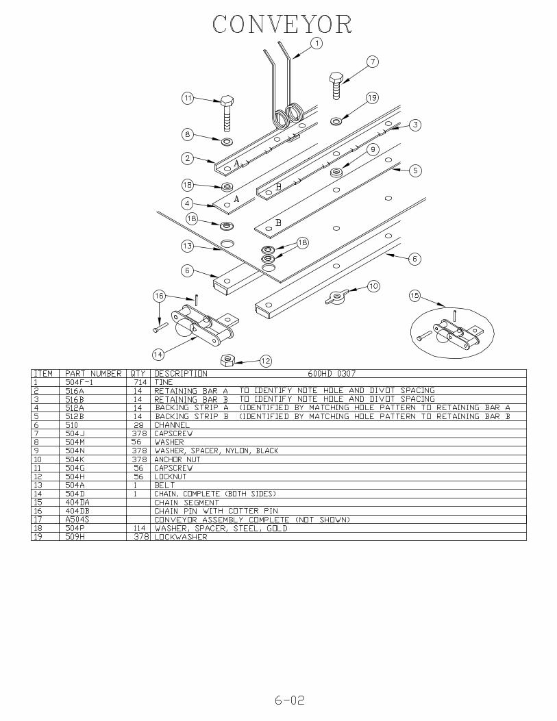
CONVEYOR The conveyor belt rakes the material off of the beach, separatesthe debris from the sand, elevates the debris up the conveyor and deposits thedebris into the hopper. The speed of the conveyor is adjustable. Proper belttension is essential for long life of the conveyor belt chains and the conveyor beltdrive components which include rollers, sprockets and bearings. If the conveyoris loose, it will cause the Surf Rake® to pick up less material and will hasten thewear of the Surf Rake’s® components.
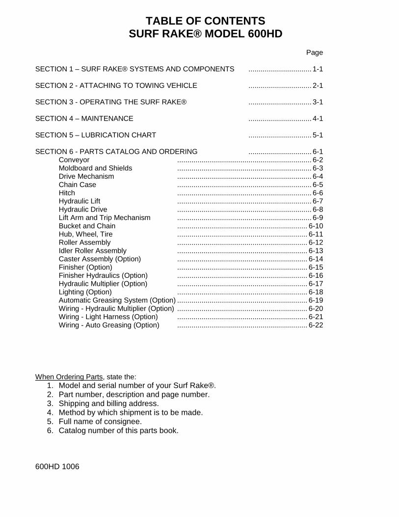
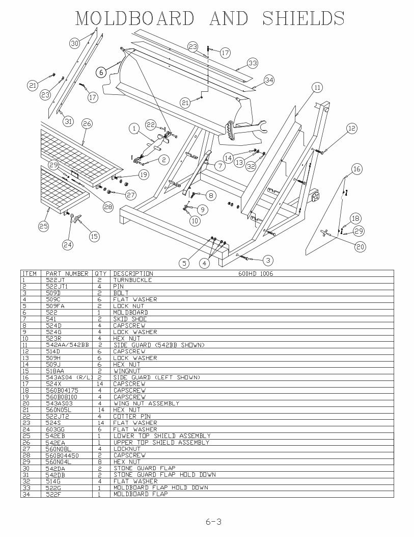
MOLDBOARD The moldboard is located behind the reservoir and in front of theconveyor. It allows debris in the path of the Surf Rake® to pass under it and into theadjacent area between the moldboard and conveyor belt where the conveyorseparates the sand and lifts the debris using the back/hidden side of the moldboard.The proper height adjustment of the moldboard is important for picking up themaximum amount of debris per pass.
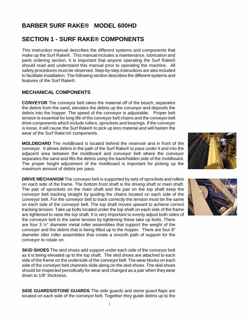
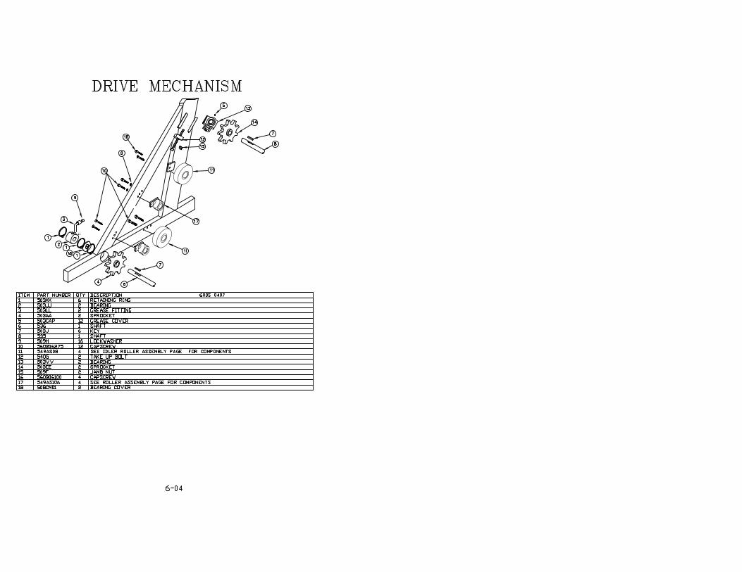
DRIVE MECHANISM The conveyor belt is supported by sets of sprockets and rollerson each side of the frame. The bottom front shaft is the driving shaft or main shaft.The pair of sprockets on the main shaft and the pair on the top shaft keep theconveyor belt tracking straight by guiding the chains located on each side of theconveyor belt. For the conveyor belt to track correctly the tension must be the sameon each side of the conveyor belt. The top shaft moves upward to achieve correcttracking tension. Take up bolts located under the top shaft on each side of the frameare tightened to raise the top shaft. It is very important to evenly adjust both sides ofthe conveyor belt to the same tension by tightening these take up bolts. Thereare four 3 ½” diameter metal roller assemblies that support the weight of theconveyor and the debris that is being lifted up to the hopper. There are four 8”diameter idler roller assemblies that create a smooth path of support for theconveyor to rotate on.
SKID SHOES The skid shoes add support under each side of the conveyor beltas it is being elevated up to the top shaft. The skid shoes are attached to eachside of the frame on the underside of the conveyor belt. The wear blocks on eachside of the conveyor belt channels slide along on the skid shoes. The skid shoesshould be inspected periodically for wear and changed as a pair when they weardown to 1/8” thickness.
SIDE GUARDS/STONE GUARDS The side guards and stone guard flaps arelocated on each side of the conveyor belt. Together they guide debris up to the
2
top of the conveyor belt and into the bucket. They keep debris away from theconveyor belt chain and drive sprockets. The side guards are fastened to theside frame with three bolts. The stone guard flaps are fastened to the sideguards with bolts which are loosened to adjust the flaps down toward the belt asthe flaps wear.
TOPSHIELD The top shield acts as a guide that prevents light weight objectsfrom being blown out the side of the moving Surf Rake®. The top shield is also asafety device that prevents incidental contact with the moving conveyor beltassembly. It is fastened to the side guard with four bolts and is taken off to adjustthe stone guard flaps.
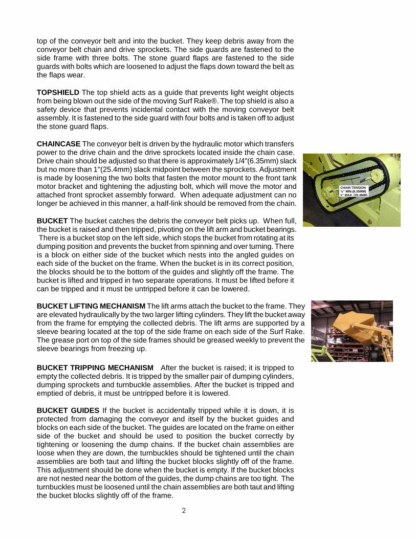
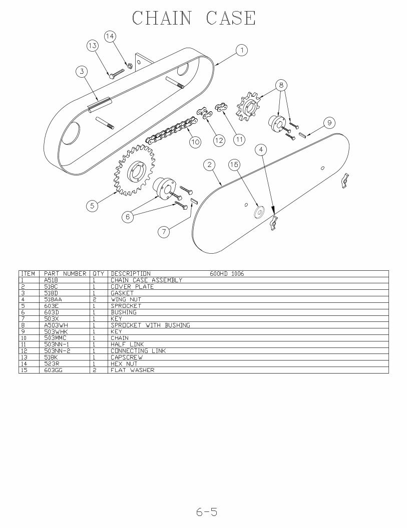
CHAINCASE The conveyor belt is driven by the hydraulic motor which transferspower to the drive chain and the drive sprockets located inside the chain case.Drive chain should be adjusted so that there is approximately 1/4"(6.35mm) slackbut no more than 1"(25.4mm) slack midpoint between the sprockets. Adjustmentis made by loosening the two bolts that fasten the motor mount to the front tankmotor bracket and tightening the adjusting bolt, which will move the motor andattached front sprocket assembly forward. When adequate adjustment can nolonger be achieved in this manner, a half-link should be removed from the chain.
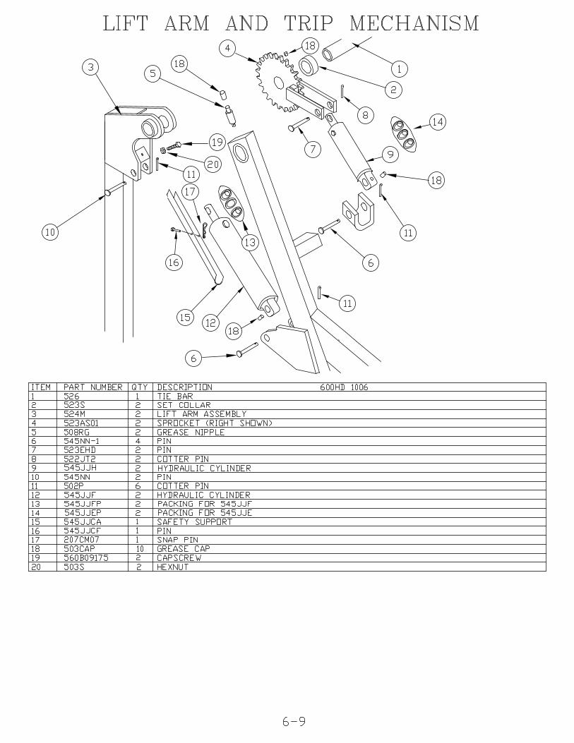
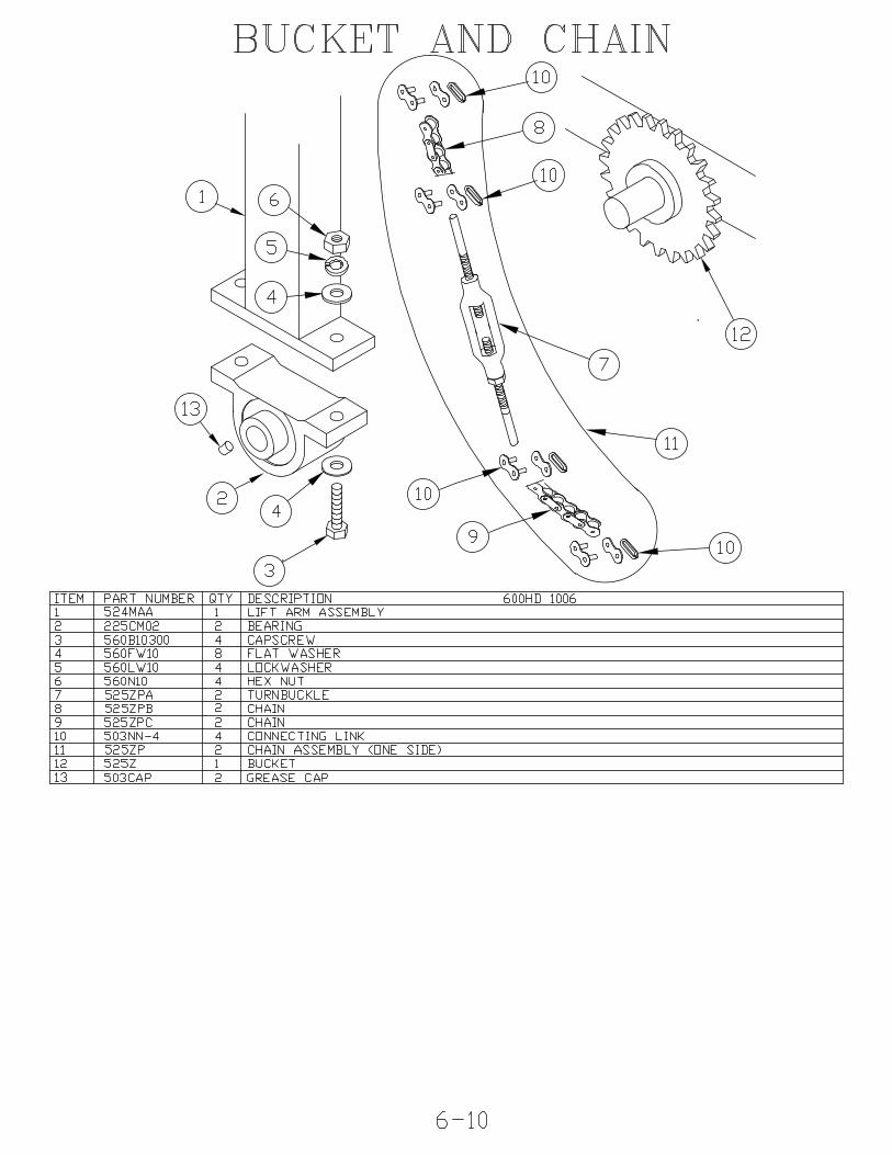
BUCKET The bucket catches the debris the conveyor belt picks up. When full,the bucket is raised and then tripped, pivoting on the lift arm and bucket bearings. There is a bucket stop on the left side, which stops the bucket from rotating at itsdumping position and prevents the bucket from spinning and over turning. Thereis a block on either side of the bucket which nests into the angled guides oneach side of the bucket on the frame. When the bucket is in its correct position,the blocks should be to the bottom of the guides and slightly off the frame. Thebucket is lifted and tripped in two separate operations. It must be lifted before itcan be tripped and it must be untripped before it can be lowered.
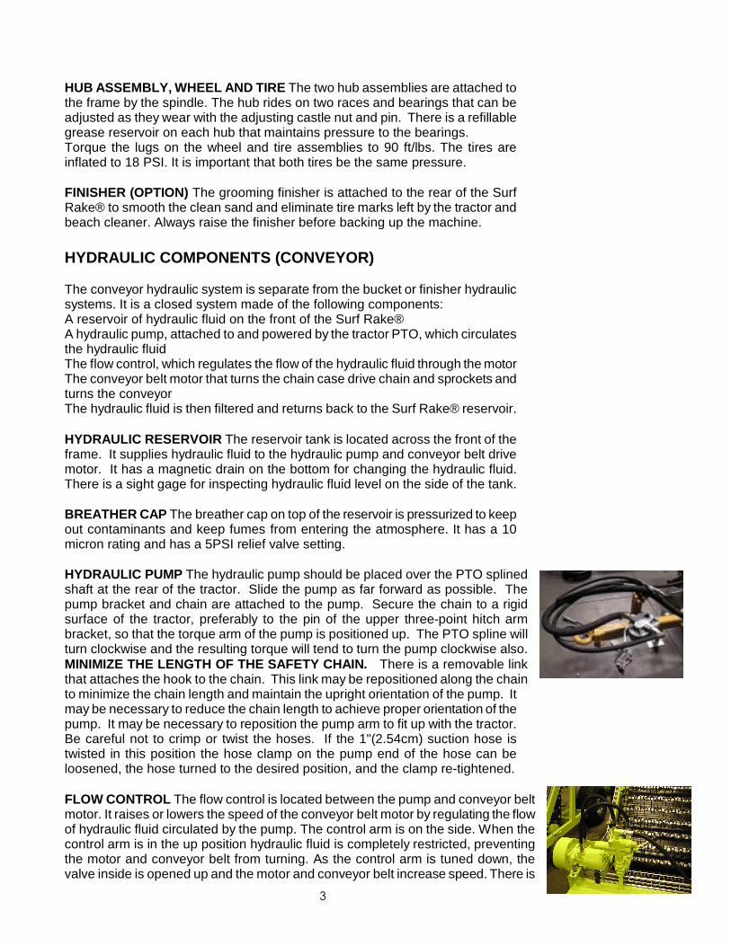
BUCKET LIFTING MECHANISM The lift arms attach the bucket to the frame. Theyare elevated hydraulically by the two larger lifting cylinders. They lift the bucket awayfrom the frame for emptying the collected debris. The lift arms are supported by asleeve bearing located at the top of the side frame on each side of the Surf Rake.The grease port on top of the side frames should be greased weekly to prevent thesleeve bearings from freezing up.
BUCKET TRIPPING MECHANISM After the bucket is raised; it is tripped toempty the collected debris. It is tripped by the smaller pair of dumping cylinders,dumping sprockets and turnbuckle assemblies. After the bucket is tripped andemptied of debris, it must be untripped before it is lowered.
BUCKET GUIDES If the bucket is accidentally tripped while it is down, it isprotected from damaging the conveyor and itself by the bucket guides andblocks on each side of the bucket. The guides are located on the frame on eitherside of the bucket and should be used to position the bucket correctly bytightening or loosening the dump chains. If the bucket chain assemblies areloose when they are down, the turnbuckles should be tightened until the chainassemblies are both taut and lifting the bucket blocks slightly off of the frame.This adjustment should be done when the bucket is empty. If the bucket blocksare not nested near the bottom of the guides, the dump chains are too tight. Theturnbuckles must be loosened until the chain assemblies are both taut and liftingthe bucket blocks slightly off of the frame.
CHAIN TENSION¼” MIN.(6.35MM)1” MAX. (25.4MM)
3
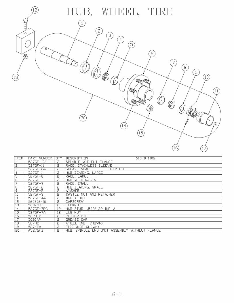
HUB ASSEMBLY, WHEEL AND TIRE The two hub assemblies are attached tothe frame by the spindle. The hub rides on two races and bearings that can beadjusted as they wear with the adjusting castle nut and pin. There is a refillablegrease reservoir on each hub that maintains pressure to the bearings.Torque the lugs on the wheel and tire assemblies to 90 ft/lbs. The tires areinflated to 18 PSI. It is important that both tires be the same pressure.
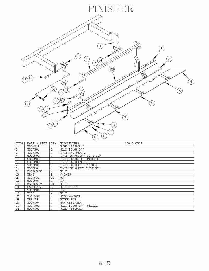
FINISHER (OPTION) The grooming finisher is attached to the rear of the SurfRake® to smooth the clean sand and eliminate tire marks left by the tractor andbeach cleaner. Always raise the finisher before backing up the machine.
HYDRAULIC COMPONENTS (CONVEYOR)
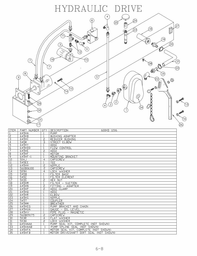
The conveyor hydraulic system is separate from the bucket or finisher hydraulicsystems. It is a closed system made of the following components:A reservoir of hydraulic fluid on the front of the Surf Rake®A hydraulic pump, attached to and powered by the tractor PTO, which circulatesthe hydraulic fluidThe flow control, which regulates the flow of the hydraulic fluid through the motorThe conveyor belt motor that turns the chain case drive chain and sprockets andturns the conveyorThe hydraulic fluid is then filtered and returns back to the Surf Rake® reservoir.
HYDRAULIC RESERVOIR The reservoir tank is located across the front of theframe. It supplies hydraulic fluid to the hydraulic pump and conveyor belt drivemotor. It has a magnetic drain on the bottom for changing the hydraulic fluid.There is a sight gage for inspecting hydraulic fluid level on the side of the tank.
BREATHER CAP The breather cap on top of the reservoir is pressurized to keepout contaminants and keep fumes from entering the atmosphere. It has a 10micron rating and has a 5PSI relief valve setting.
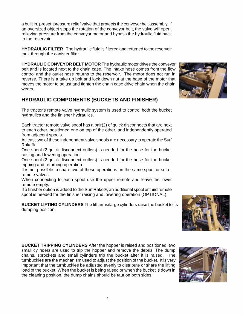
HYDRAULIC PUMP The hydraulic pump should be placed over the PTO splinedshaft at the rear of the tractor. Slide the pump as far forward as possible. Thepump bracket and chain are attached to the pump. Secure the chain to a rigidsurface of the tractor, preferably to the pin of the upper three-point hitch armbracket, so that the torque arm of the pump is positioned up. The PTO spline willturn clockwise and the resulting torque will tend to turn the pump clockwise also.MINIMIZE THE LENGTH OF THE SAFETY CHAIN. There is a removable linkthat attaches the hook to the chain. This link may be repositioned along the chainto minimize the chain length and maintain the upright orientation of the pump. Itmay be necessary to reduce the chain length to achieve proper orientation of thepump. It may be necessary to reposition the pump arm to fit up with the tractor.Be careful not to crimp or twist the hoses. If the 1"(2.54cm) suction hose istwisted in this position the hose clamp on the pump end of the hose can beloosened, the hose turned to the desired position, and the clamp re-tightened.
FLOW CONTROL The flow control is located between the pump and conveyor beltmotor. It raises or lowers the speed of the conveyor belt motor by regulating the flowof hydraulic fluid circulated by the pump. The control arm is on the side. When thecontrol arm is in the up position hydraulic fluid is completely restricted, preventingthe motor and conveyor belt from turning. As the control arm is tuned down, thevalve inside is opened up and the motor and conveyor belt increase speed. There is
4
a built in, preset, pressure relief valve that protects the conveyor belt assembly. Ifan oversized object stops the rotation of the conveyor belt, the valve will open,relieving pressure from the conveyor motor and bypass the hydraulic fluid backto the reservoir.
HYDRAULIC FILTER The hydraulic fluid is filtered and returned to the reservoirtank through the canister filter.
HYDRAULIC CONVEYOR BELT MOTOR The hydraulic motor drives the conveyorbelt and is located next to the chain case. The intake hose comes from the flowcontrol and the outlet hose returns to the reservoir. The motor does not run inreverse. There is a take up bolt and lock down nut at the base of the motor thatmoves the motor to adjust and tighten the chain case drive chain when the chainwears.
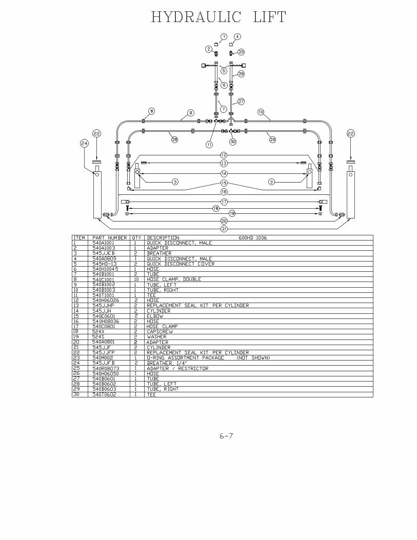
HYDRAULIC COMPONENTS (BUCKETS AND FINISHER)
The tractor’s remote valve hydraulic system is used to control both the buckethydraulics and the finisher hydraulics.
Each tractor remote valve spool has a pair(2) of quick disconnects that are nextto each other, positioned one on top of the other, and independently operatedfrom adjacent spools.At least two of these independent valve spools are necessary to operate the SurfRake®.One spool (2 quick disconnect outlets) is needed for the hose for the bucketraising and lowering operation.One spool (2 quick disconnect outlets) is needed for the hose for the buckettripping and returning operationIt is not possible to share two of these operations on the same spool or set ofremote valves.When connecting to each spool use the upper remote and leave the lowerremote empty.If a finisher option is added to the Surf Rake®, an additional spool or third remotespool is needed for the finisher raising and lowering operation (OPTIONAL).
BUCKET LIFTING CYLINDERS The lift arms/large cylinders raise the bucket to itsdumping position.
BUCKET TRIPPING CYLINDERS After the hopper is raised and positioned, twosmall cylinders are used to trip the hopper and remove the debris. The dumpchains, sprockets and small cylinders trip the bucket after it is raised. Theturnbuckles are the mechanism used to adjust the position of the bucket. It is veryimportant that the turnbuckles be adjusted evenly to distribute or share the liftingload of the bucket. When the bucket is being raised or when the bucket is down inthe cleaning position, the dump chains should be taut on both sides.
5
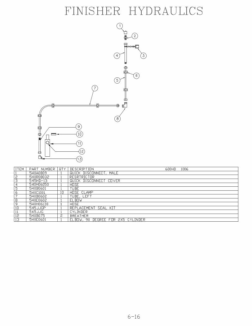
FINISHER CYLINDER (OPTION) The finisher cylinder is operated hydraulicallythrough a hose connected to one of the tractor’s quick disconnecting remotevalves. The finisher cylinder lowers the finisher onto the beach to create a smoothpathway behind the Surf Rake®. The finisher cylinder raises the finisher fortransporting to and from either a debris dump site or dumpster and for transportingthe Surf Rake® to a storage site.
ELECTRONIC COMPONENTS (OPTIONS)
Electrical diagrams for all component options are located at the end of thismanual.
POWER CABLE The towing tractor supplies the Surf Rake® and all its electroniccomponents with power through the seven conductor power cable. The cable runsfrom the tractor to the junction box on the Surf Rake®. Wiring diagrams are locatedat the back of this manual – refer to the table of contents.
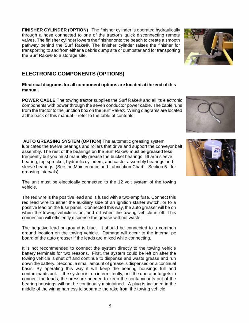
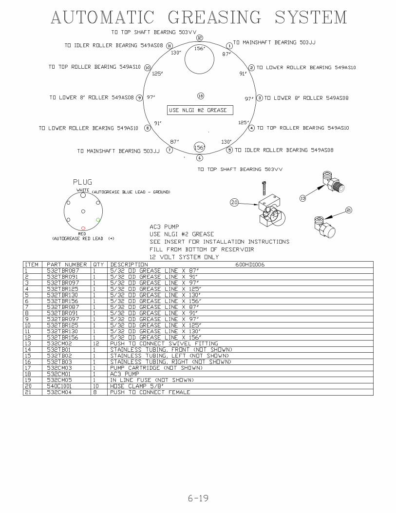
AUTO GREASING SYSTEM (OPTION) The automatic greasing systemlubricates the twelve bearings and rollers that drive and support the conveyor beltassembly. The rest of the bearings on the Surf Rake® must be greased lessfrequently but you must manually grease the bucket bearings, lift arm sleevebearing, top sprocket, hydraulic cylinders, and caster assembly bearings andsleeve bearings. (See the Maintenance and Lubrication Chart – Section 5 - forgreasing intervals)
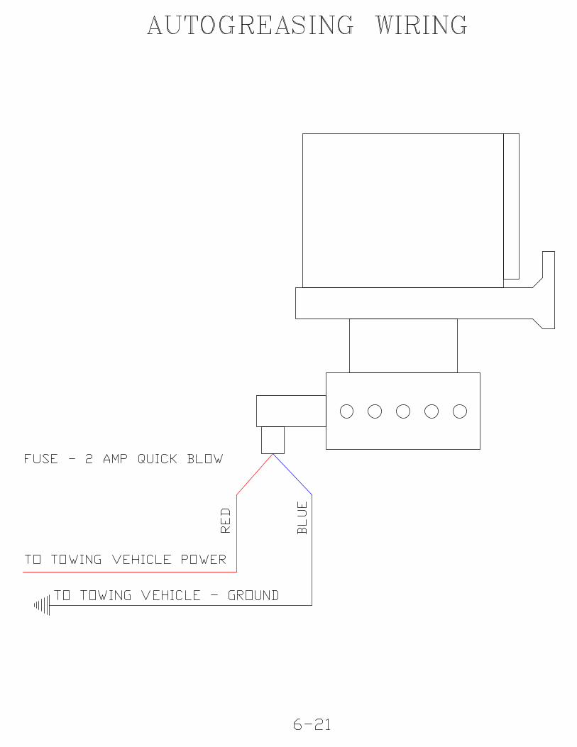
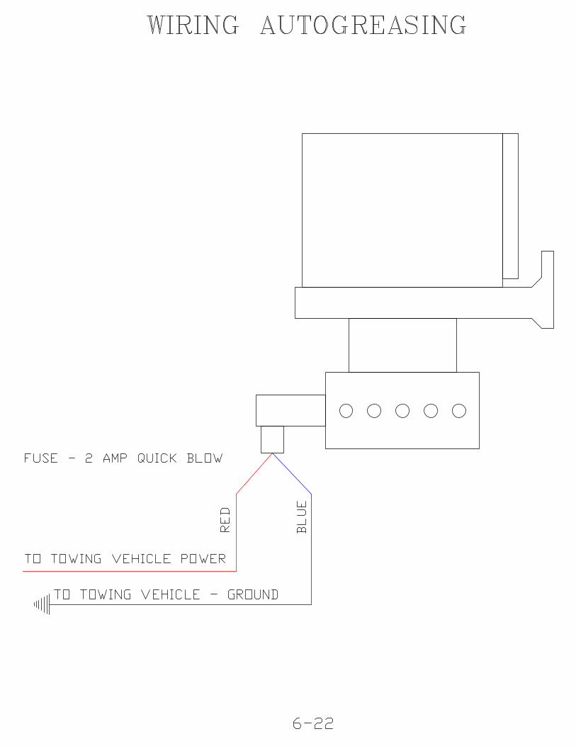
The unit must be electrically connected to the 12 volt system of the towingvehicle.
The red wire is the positive lead and is fused with a two-amp fuse. Connect thisred lead wire to either the auxiliary side of an ignition starter switch, or to apositive lead on the fuse panel. Connected this way, the auto greaser will be onwhen the towing vehicle is on, and off when the towing vehicle is off. Thisconnection will efficiently dispense the grease without waste.
The negative lead or ground is blue. It should be connected to a commonground location on the towing vehicle. Damage will occur to the internal pcboard of the auto greaser if the leads are mixed while connecting.
It is not recommended to connect the system directly to the towing vehiclebattery terminals for two reasons. First, the system could be left on after thetowing vehicle is shut off and continue to dispense and waste grease and rundown the battery. Second, a small amount of grease is dispensed on a continualbasis. By operating this way it will keep the bearing housings full andcontaminants out. If the system is run intermittently, or if the operator forgets toconnect the leads, the pressure needed to keep the contaminants out of thebearing housings will not be continually maintained. A plug is included in themiddle of the wiring harness to separate the rake from the towing vehicle.
6
There is a button and corresponding green light on the bottom of the motorhousing under the reservoir assembly that, when pressed, will start/override theinternal, preset timer. This will start the motor, which will rotate the paddle andcam and dispense grease into the injectors and through the grease lines. Thepaddle/motor assembly will turn one revolution and stop when this overridebutton is used. This procedure can be repeated by repressing the button. It isuseful for determining that the unit is hooked up correctly or to fill a new injectoror grease line with grease.
Inside the reservoir, the paddle/cam drive is preset to turn at one revolution every11 minutes. The reservoir is pre filled and tested with NLGI #2 grease. Thepaddle presses the grease down to the injector intake area. The cam opens theindividual injectors allowing grease to enter. There is an indicator wiper on thepaddle which wipes the side of the reservoir as it rotates around the inside of thereservoir, indicating that the unit is functioning.
The injectors dispense .040 cc per revolution of the paddle in the reservoir.
The Reservoir is filled through a grease zerk fitting on the side of the unit. As thegrease is filling the reservoir, it is recommended that you turn the unit on so thepaddle will keep the grease level as it rises inside.
If the paddle in the reservoir does not turn:
1. Check the Fuse. Replace, if necessary with a 2 amp quick blow fuse.
2. Check for correct wiring and wiring continuity. The red wire is the powerlead and the blue wire is the ground lead. If polarity is reversed, the electronictiming board inside may be damaged.
3. Press the reset button on the bottom of the reservoir; check the adjacentlight to see if the paddle in the reservoir is turning.
Make sure the reservoir is not overfilled with grease. There are minimum andmaximum lines on the label on the reservoir. Check the condition of thegrease. If the grease has been sitting during the off season or any longperiod of time, the oil may have separated, solidifying the medium and makingit too heavy for the system to pump. If this is the case, remove the solidifiedgrease and clean out the reservoir with a light weight mineral oil. Do not useany commercial cleaners to purge any part of the auto greasing system asthey will damage “o”rings and other rubber or plastic components.
When washing near the auto greaser reservoir, do not allow water to splashor spray up into the breather tube which is molded on the side of the reservoir.
Check all lines for kinks or bends. Check to insure that all grease lines areattached.
It is recommended that the injectors be replaced after four years of use.
7
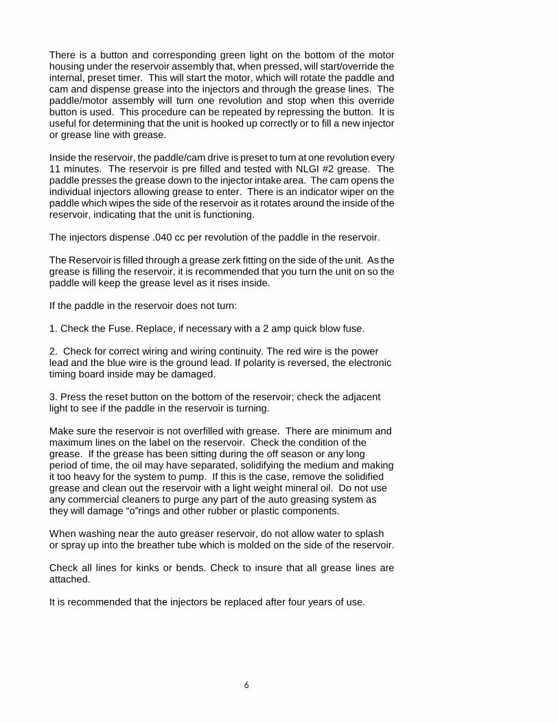
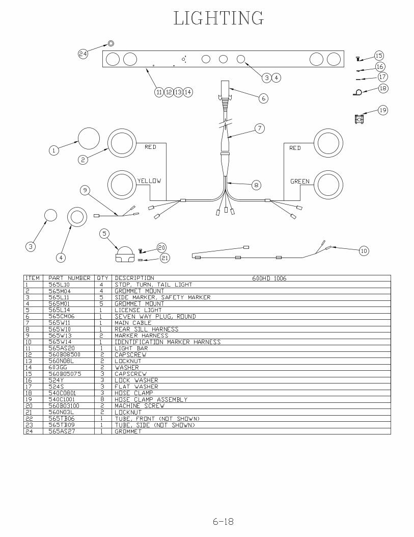
LIGHTING (OPTION) The lighting circuit is comprised of a two piece moldedelectrical harness that connects the brake lights, taillights, directional lights, markerlights, safety lights and running lights of the Surf Rake®’s light bar to the towingvehicle’s lighting system. The Electrical plug is a 7-pin configuration. Wiringdiagrams are at the end of Section 6.
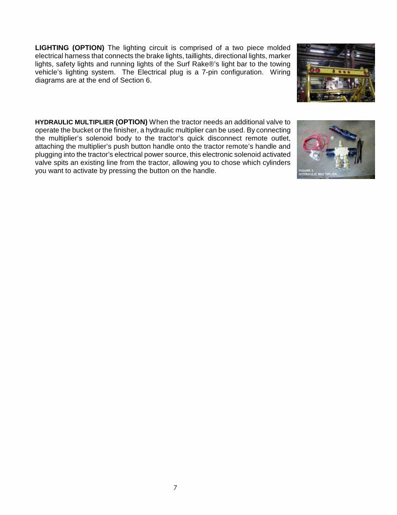
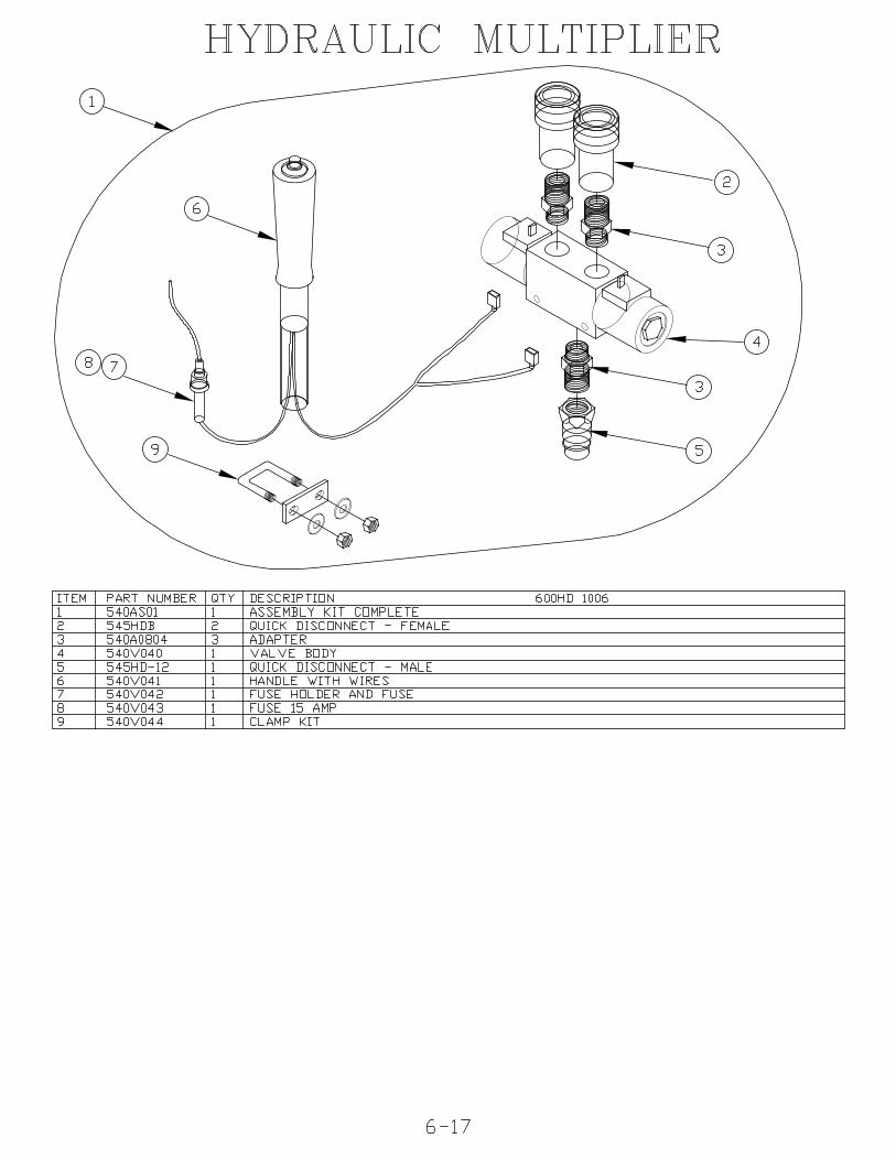
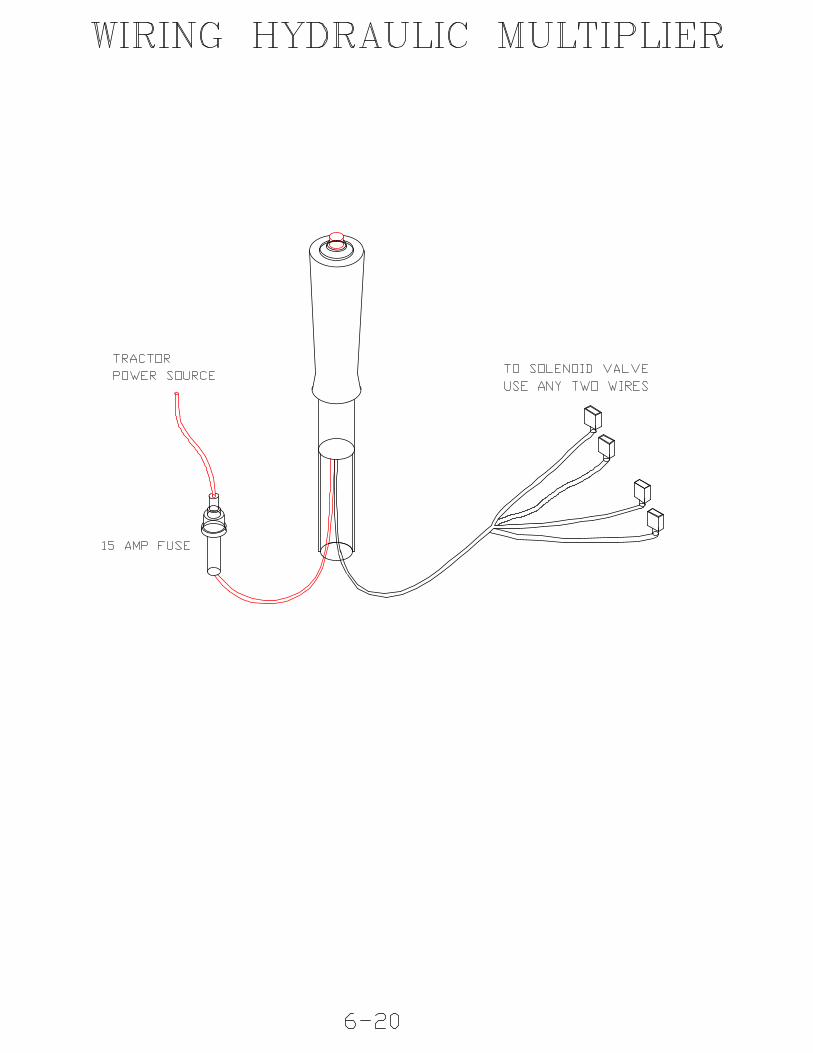
HYDRAULIC MULTIPLIER (OPTION) When the tractor needs an additional valve tooperate the bucket or the finisher, a hydraulic multiplier can be used. By connectingthe multiplier’s solenoid body to the tractor’s quick disconnect remote outlet,attaching the multiplier’s push button handle onto the tractor remote’s handle andplugging into the tractor’s electrical power source, this electronic solenoid activatedvalve spits an existing line from the tractor, allowing you to chose which cylindersyou want to activate by pressing the button on the handle.
1
BARBER SURF RAKE® MODEL 600HD
SECTION 2 - ATTACHING TO TOWING VEHICLEThis instruction manual describes the different systems and components thatmake up the Surf Rake®. This manual includes a maintenance, lubrication andparts ordering section. It is important that anyone operating the Surf Rake®should read and understands this manual prior to operating. All safetyprocedures must be observed. Step-by-step instructions are also included tofacilitate installation. The following section describes the different, systems andfeatures of the Surf Rake®.
ATTACH
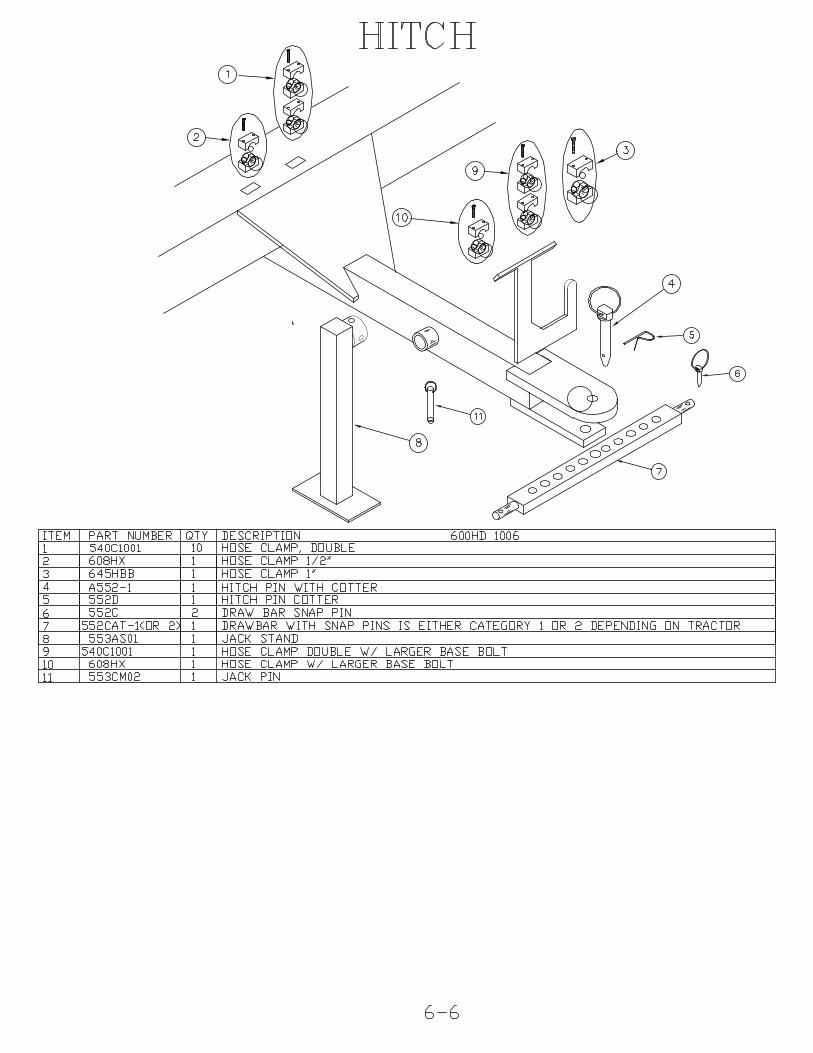
DRAWBAR Install the supplied draw bar onto the tractor's lower 3-point hitch arms,securing it on each end with the supplied hitch bar snap pins.
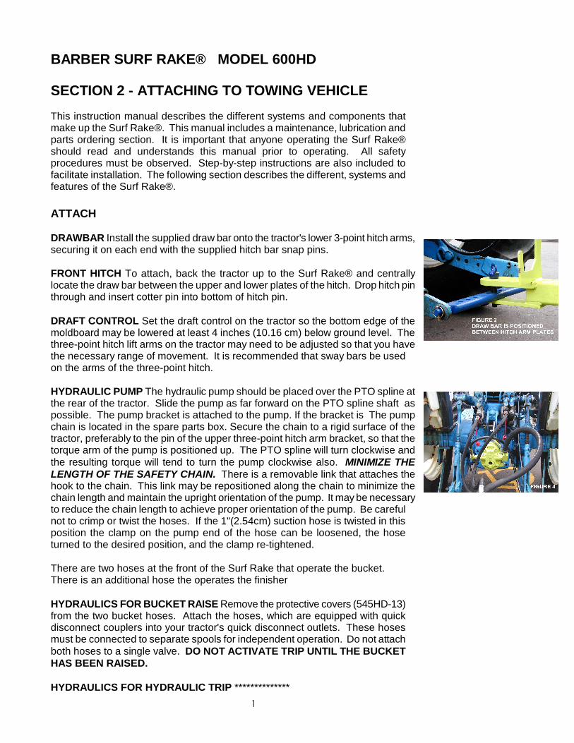
FRONT HITCH To attach, back the tractor up to the Surf Rake® and centrallylocate the draw bar between the upper and lower plates of the hitch. Drop hitch pinthrough and insert cotter pin into bottom of hitch pin.
DRAFT CONTROL Set the draft control on the tractor so the bottom edge of themoldboard may be lowered at least 4 inches (10.16 cm) below ground level. Thethree-point hitch lift arms on the tractor may need to be adjusted so that you havethe necessary range of movement. It is recommended that sway bars be usedon the arms of the three-point hitch.
HYDRAULIC PUMP The hydraulic pump should be placed over the PTO spline atthe rear of the tractor. Slide the pump as far forward on the PTO spline shaft aspossible. The pump bracket is attached to the pump. If the bracket is The pumpchain is located in the spare parts box. Secure the chain to a rigid surface of thetractor, preferably to the pin of the upper three-point hitch arm bracket, so that thetorque arm of the pump is positioned up. The PTO spline will turn clockwise andthe resulting torque will tend to turn the pump clockwise also. MINIMIZE THELENGTH OF THE SAFETY CHAIN. There is a removable link that attaches thehook to the chain. This link may be repositioned along the chain to minimize thechain length and maintain the upright orientation of the pump. It may be necessaryto reduce the chain length to achieve proper orientation of the pump. Be carefulnot to crimp or twist the hoses. If the 1"(2.54cm) suction hose is twisted in thisposition the clamp on the pump end of the hose can be loosened, the hoseturned to the desired position, and the clamp re-tightened.
There are two hoses at the front of the Surf Rake that operate the bucket.There is an additional hose the operates the finisher
HYDRAULICS FOR BUCKET RAISE Remove the protective covers (545HD-13)from the two bucket hoses. Attach the hoses, which are equipped with quickdisconnect couplers into your tractor's quick disconnect outlets. These hosesmust be connected to separate spools for independent operation. Do not attachboth hoses to a single valve. DO NOT ACTIVATE TRIP UNTIL THE BUCKETHAS BEEN RAISED.
HYDRAULICS FOR HYDRAULIC TRIP **************
2
HYDRAULICS FOR FINISHER The conveyor belt is driven by the hydraulicmotor which transfers power to the drive chain and the drive sprockets locatedinside the chain case. Drive chain should be adjusted so that there isapproximately 1/4"(6.35mm) slack but no more than 1"(25.4mm) slack midpointbetween the sprockets. Adjustment is made by loosening the two bolts thatfasten the motor mount to the front tank motor bracket and tightening theadjusting bolt, which will move the motor and attached front sprocket assemblyforward. When adequate adjustment can no longer be achieved in this manner,a half-link should be removed from the chain.
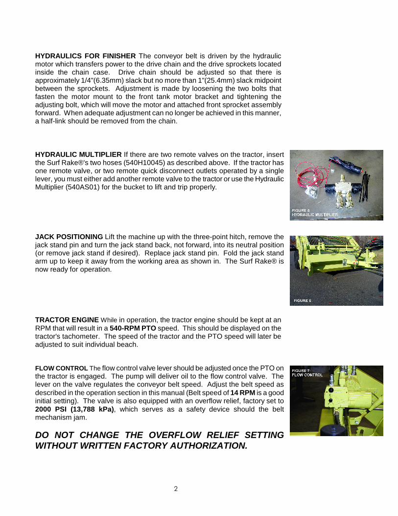
HYDRAULIC MULTIPLIER If there are two remote valves on the tractor, insertthe Surf Rake®'s two hoses (540H10045) as described above. If the tractor hasone remote valve, or two remote quick disconnect outlets operated by a singlelever, you must either add another remote valve to the tractor or use the HydraulicMultiplier (540AS01) for the bucket to lift and trip properly.
JACK POSITIONING Lift the machine up with the three-point hitch, remove thejack stand pin and turn the jack stand back, not forward, into its neutral position(or remove jack stand if desired). Replace jack stand pin. Fold the jack standarm up to keep it away from the working area as shown in. The Surf Rake® isnow ready for operation.
TRACTOR ENGINE While in operation, the tractor engine should be kept at anRPM that will result in a 540-RPM PTO speed. This should be displayed on thetractor's tachometer. The speed of the tractor and the PTO speed will later beadjusted to suit individual beach.
FLOW CONTROL The flow control valve lever should be adjusted once the PTO onthe tractor is engaged. The pump will deliver oil to the flow control valve. Thelever on the valve regulates the conveyor belt speed. Adjust the belt speed asdescribed in the operation section in this manual (Belt speed of 14 RPM is a goodinitial setting). The valve is also equipped with an overflow relief, factory set to2000 PSI (13,788 kPa), which serves as a safety device should the beltmechanism jam.
DO NOT CHANGE THE OVERFLOW RELIEF SETTINGWITHOUT WRITTEN FACTORY AUTHORIZATION.
BARBER SURF RAKE® MODEL 600HD
SECTION 3 – OPERATING THE SURF RAKE®
OPERATION
Do not allow individuals to operate the Surf Rake® withoutfirst receiving personalized training and ensuring that theyhave read this manual.
Before each operation of the Surf Rake®, make a careful visualinspection of the machine. Do not operate if you observedamaged or missing parts, missing guards, excessive wear orunusual noise or vibration during startup.
Stand clear of hydraulic hoses and fittings while the Surf Rake®is in operation. A sudden fitting or hose failure can inflictserious injury.
To prevent the tractor and/or Surf Rake® from capsizing andcausing serious injury or death, do not operate the Surf Rake® ona steep incline or unstable surface.
Do not allow a bystander to approach the Surf Rake® unlessthat individual is qualified and is present to assist in theoperation or repair of the machine. Never allow one person tooperate the controls of the Surf Rake® while another has anypart of their body in or near a pinch point.
Under no circumstances should a bystander stand under or nearthe hopper while it is being raised or lowered.
To prevent injury, do not attempt to clear large obstacles bypushing them with the tractor or Surf Rake®.
Never attempt to clear a jam by placing hands or any part of thebody into or near the machinery that has not been completelyshut down. A jammed conveyor component can immediatelyjump into motion and cause serious injury to hands or other bodyparts in immediate contact with the components if the system isunder hydraulic pressure.
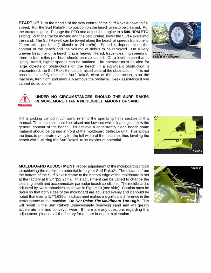
START UP Turn the handle of the flow control of the Surf Rake® down to fullspeed. Pull the Surf Rake® into position on the beach area to be cleaned. Putthe tractor in gear. Engage the PTO and adjust the engine to a 540-RPM PTOsetting. With the tractor moving and the belt turning, lower the Surf Rake® intothe sand. The Surf Rake® can be towed along the beach at speeds from one tofifteen miles per hour (1.6km/hr to 24 km/hr). Speed is dependent on thecontour of the beach and the volume of debris to be removed. On a veryuneven beach or on a beach that is heavily littered, travel-cleaning speeds ofthree to four miles per hour should be maintained. On a level beach that islightly littered, higher speeds can be attained. The operator must be alert forlarge objects or obstructions on the beach. If a significant obstruction isencountered, the Surf Rake® must be raised clear of the obstruction. If it is notpossible to safely raise the Surf Rake® clear of the obstruction, stop themachine, turn it off, and manually remove the obstacle. Seek assistance if youcannot do so alone.
UNDER NO CIRCUMSTANCES SHOULD THE SURF RAKE®REMOVE MORE THAN A NEGLIGIBLE AMOUNT OF SAND.
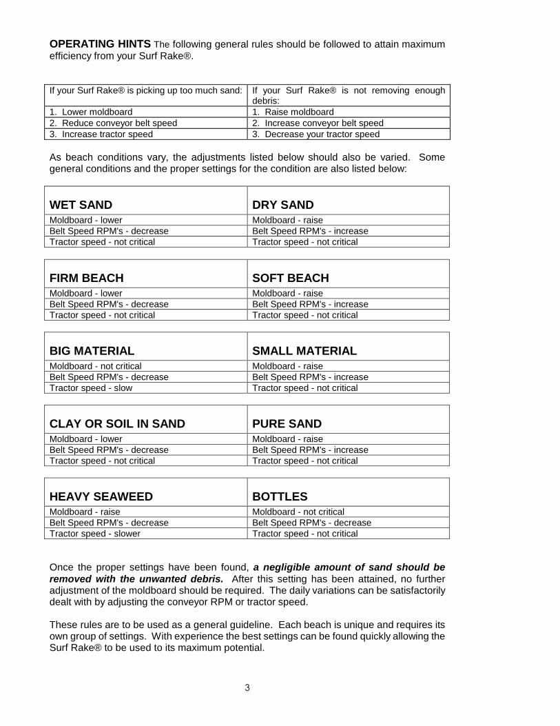
If it is picking up too much sand refer to the operating hints section of thismanual. The machine should be raised and lowered while cleaning to follow thegeneral contour of the beach. To achieve a consistently clean beach somematerial should be carried in front of the moldboard deflector unit. This allowsthe tines to penetrate evenly for the full width of the machine, thus leveling thebeach while utilizing the Surf Rake® to its maximum potential.
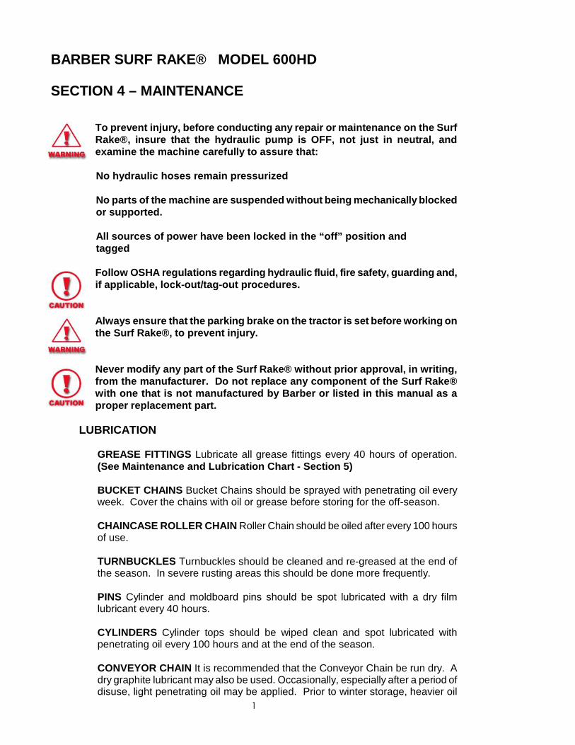
MOLDBOARD ADJUSTMENT Proper adjustment of the moldboard is criticalto achieving the maximum potential from your Surf Rake®. The distance fromthe bottom of the Surf Rake® frame to the bottom edge of the moldboard is setat the factory at 8 3/4"(22.2cm). This adjustment can be varied to change thecleaning depth and accommodate particular beach conditions. The moldboard isadjusted by two turnbuckles as shown in Figure 10 (one side). Caution must betaken so that both sides of the moldboard are adjusted evenly and it should benoted that even a 1/4"(.635cm) adjustment makes a significant difference in theperformance of the machine. Do Not Raise The Moldboard Too High. Thiswill result in the Surf Rake® unnecessarily removing sand and will greatlyaccelerate tine and conveyor wear. If there are any questions regarding thisadjustment, please call the factory for a more in-depth explanation.
3
OPERATING HINTS The following general rules should be followed to attain maximumefficiency from your Surf Rake®.
If your Surf Rake® is picking up too much sand: If your Surf Rake® is not removing enoughdebris:
1. Lower moldboard 1. Raise moldboard2. Reduce conveyor belt speed 2. Increase conveyor belt speed3. Increase tractor speed 3. Decrease your tractor speed
As beach conditions vary, the adjustments listed below should also be varied. Somegeneral conditions and the proper settings for the condition are also listed below:
WET SAND DRY SANDMoldboard - lower Moldboard - raiseBelt Speed RPM's - decrease Belt Speed RPM's - increaseTractor speed - not critical Tractor speed - not critical
FIRM BEACH SOFT BEACHMoldboard - lower Moldboard - raiseBelt Speed RPM's - decrease Belt Speed RPM's - increaseTractor speed - not critical Tractor speed - not critical
BIG MATERIAL SMALL MATERIALMoldboard - not critical Moldboard - raiseBelt Speed RPM's - decrease Belt Speed RPM's - increaseTractor speed - slow Tractor speed - not critical
CLAY OR SOIL IN SAND PURE SANDMoldboard - lower Moldboard - raiseBelt Speed RPM's - decrease Belt Speed RPM's - increaseTractor speed - not critical Tractor speed - not critical
HEAVY SEAWEED BOTTLESMoldboard - raise Moldboard - not criticalBelt Speed RPM's - decrease Belt Speed RPM's - decreaseTractor speed - slower Tractor speed - not critical
Once the proper settings have been found, a negligible amount of sand should beremoved with the unwanted debris. After this setting has been attained, no furtheradjustment of the moldboard should be required. The daily variations can be satisfactorilydealt with by adjusting the conveyor RPM or tractor speed.
These rules are to be used as a general guideline. Each beach is unique and requires itsown group of settings. With experience the best settings can be found quickly allowing theSurf Rake® to be used to its maximum potential.
1
BARBER SURF RAKE® MODEL 600HD
SECTION 4 – MAINTENANCE
To prevent injury, before conducting any repair or maintenance on the SurfRake®, insure that the hydraulic pump is OFF, not just in neutral, andexamine the machine carefully to assure that:
No hydraulic hoses remain pressurized
No parts of the machine are suspended without being mechanically blocked or supported.
All sources of power have been locked in the “off” position and tagged
Always ensure that the parking brake on the tractor is set before working onthe Surf Rake®, to prevent injury.
Never modify any part of the Surf Rake® without prior approval, in writing,from the manufacturer. Do not replace any component of the Surf Rake®with one that is not manufactured by Barber or listed in this manual as aproper replacement part.
LUBRICATION
GREASE FITTINGS Lubricate all grease fittings every 40 hours of operation.(See Maintenance and Lubrication Chart - Section 5)
BUCKET CHAINS Bucket Chains should be sprayed with penetrating oil everyweek. Cover the chains with oil or grease before storing for the off-season.
CHAINCASE ROLLER CHAIN Roller Chain should be oiled after every 100 hoursof use.
TURNBUCKLES Turnbuckles should be cleaned and re-greased at the end ofthe season. In severe rusting areas this should be done more frequently.
PINS Cylinder and moldboard pins should be spot lubricated with a dry filmlubricant every 40 hours.
CYLINDERS Cylinder tops should be wiped clean and spot lubricated withpenetrating oil every 100 hours and at the end of the season.
CONVEYOR CHAIN It is recommended that the Conveyor Chain be run dry. Adry graphite lubricant may also be used. Occasionally, especially after a period ofdisuse, light penetrating oil may be applied. Prior to winter storage, heavier oil
2
may be applied to avoid rusting.
BARBER SURF RAKE® MAINTENANCE ADJUSTMENTS
DAILY ADJUSTMENT CHECK There are four basic component checks for properadjustment to insure that your Surf Rake® is operating to the efficiency for which itwas designed. The four adjustments work together and should be checked eachtime the machine is used.
TIRE PRESSURE
It is important for the proper operation of the Surf Rake® to have the two rear tiresinflated to the same pressure.
To Adjust Tire Pressure: Inflate tires to 18 PSI.
When the tires are not inflated the same the tire with the lower pressure will in turnlower that side of the Surf Rake® and cause the tines on that side to be lower. Theresult is the conveyor belt will clean unevenly, possibly picking up sand on the lowerside or not cleaning deep enough on the higher side.
BUCKET / LIFTARM CHAIN ASSEMBLIES
It is important for the proper operation of the Surf Rake® to have the bucket/lift armchains on each side of the Surf Rake® under the same tension, and not loose, sothey will share the load when lifting and tripping the hopper.
To Adjust Bucket Chains: When the bucket is sitting on the frame, thechain/turnbuckle assemblies should not be loose. Tighten up loosechain/turnbuckle assemblies so that both sides have the same tension and thebucket support blocks are just off or barely touching the frame.
When one chain assembly is loose while raising the bucket, all the weight andpressure of lifting the bucket is shifted to the tighter chain assembly. Thiscauses the tighter chain assembly to stretch more than it would if both chainassemblies were the same tension. This causes premature wear to the linksand the chains and can cause sudden failure to one or both of the chainassemblies. If both chains become loose, the bucket will not fully return tothe forward/bottom position and will bottom out farther back on the fame thanit should. This will allow a gap between the bucket and the path of the debrisbeing picked up that allows the debris to drop down in front of the bucketwhen the machine is operating.
CONVEYOR BELT TENSION
It is important for the proper operation of the Surf Rake® to have both sides of theconveyor belt with the same tension.
To Adjust the Conveyor Belt: Open the side guard doors on both sides of the Surf
3
Rake®. Pull the conveyor belt back and forth midway between the upper 8” idlerroller wheel and lower 8” idler roller wheel to check for amount of play. If there ismore than 1 ½” of play, tighten the adjusting bolt. This will raise the upper shaft andtighten the conveyor assembly. Repeat this procedure on the other side of theconveyor assembly. Take some time and go back and forth to each side of themachine, checking that both sides are the same tension. Once both sides are thesame tension, retighten the jam nuts on the take up bolts and refasten thedoors/guards.
When the conveyor belt assembly is loose on one side the belt it will naturally sagon that side and cause the tines to drag on that side. The result is premature wearto the tines, an uneven cleaning and possible picking up of sand.
MOLDBOARD HEIGHT
It is important for the proper operation of the Surf Rake® to have both sides of themoldboard adjusted identically to the same height. The moldboard is initially setevenly. For most applications, this factory setting works well. If the factory setting ischanged, be advised that a small amount of adjustment has dramatic results. Donot move more than ¼” at a time without testing the new setting in the sand for aperiod of time. Use the guides at the sides of the moldboard to align both sidesidentically.
To Adjust: Loosen the turnbuckle locking arms on the sides to be moved. Use theguides at each side of the moldboard to level the moldboard to the desired height.Be sure that the guides are set at the same mark or location on each side.Retighten the turnbuckle locking arm/s.
The moldboard levels the beach so the tines can penetrate and clean the sand to aconstant depth. If the moldboard is too high on one side the tines will be forced toodeep into the sand. This will result in sand being removed along with the debris. Atno time should the Barber Surf Rake® pick up sand.
CONVEYOR BELT DRIVE MECHANISM INSPECTION, ADJUSTMENT
MAINSHAFT
Main Shaft Sprockets
Make a visual inspection of the sprockets for wear. If the sprocket toothis worn down half of its original width, it should be replaced. There is noadjustment to be made on the sprockets.
Main Shaft Bearings
Try and lift the main shaft either with a pry bar or by hand. If there is play ormovement an adjustment can be made to tighten the bearing.
4
To Adjust The Main Shaft Bearings:
Unscrew machine screw on side of main shaft bearing and remove retaining ringstop. Turn retaining ring clockwise until there is little or no play. Reinsert the stopand screw. Do not over tighten. The drive chain and drive sprocket must beremoved to adjust the bearing on the chain case side. If adjusting does not removethe play from the bearing, it must be replaced.
To Remove The Main Shaft Bearings:
Remove the Top shield, Side Guards, and Conveyor belt assemblies.Remove the chain case cover.Loosen the motor jam nut and take up bolt.Loosen the motor mount bolts and slide back the motor to loosen the drive chain.Remove drive chain.Remove large drive sprocket.Loosen the setscrews on the cast iron conveyor belt sprocket that is farthestaway from the chain case - the left side.Clean the paint off of the inner/left side of the main shaft and move the left sidecast iron conveyor belt sprocket toward the center of the main shaft.Remove the left/outer-retaining ring, which holds the cartridge bearing in itssleeve.Pull the main shaft away from the chain case so that the left bearing slides out ofits sleeve and can be taken off of the shaft.Remove the right inner retaining ring and push the cartridge bearing out of itssleeve.If the cartridge bearing is locked into place a bearing puller can be purchased tohelp remove the bearing.
TOPSHAFT
Top Shaft Sprockets
Make a visual inspection of the sprockets for wear. If the sprocket tooth is worndown half of its original thickness, it should be replaced. There is no adjustment tobe made on the sprockets
Top Shaft Bearings
The top shaft bearings are take-up bearings. Clean off any debris or excess greaseand visually inspect for wear or damage. Use a pry bar to check for wear pushingon the bar to inspect for movement. If there is no movement, clean and grease. Ifthe bearing or sprockets are visibly damaged or have movement they must bereplaced.
5
To Remove the Top Shaft
Raise the bucket and secure it with the safety support. (545JJCA)
Remove the top shield. Loosen up the six 1/2" wing nuts (518AA) that secure thetop shield to the side shields. The top shield is hinged. Flip up the lower section ofthe top shield so it rests on the upper section of the top shield. Remove the topshield assembly by lifting it off the side shields.
Remove side shields.
The side shields are slotted so that they can be lifted off the frame once the boltsthat attach them to the frame are loosened (four bolts) or removed (two bolts).There are three 3/8” bolts on each side, which secure each guard. The top setof bolts has no hidden nuts and loosens with either a 9/16” socket or box wrench. They can be completely removed from the frame.
The middle set of bolts has nuts, which are accessible and hidden on the insideof the frame. They should be partially loosened with a 9/16” socket and box endwrench. Loosen three or four turns but do not remove from the frame.
One of the bottom bolts/nut is accessible behind the chain case and must beloosened three or four turns with an open end wrench. The other bottom boltcan be loosened three or four turns with a 9/16” socket and box end wrench.Raise the bottom end of the side guard first, and then lift the guard off of thebolts.
Remove the two ½” wing nuts that secure the chain case cover to the chain case.Remove the chain case cover. Position the connecting link midway between thelarge and small drive sprockets. Remove the connecting link and the drive chain.The tractor can be uncoupled from the Surf Rake® at this point.
There is an overlap at the ends of the conveyor belt rubber belting. The overlap isunder one of the rows of springs. The belt must be disconnected at this overlappedrow. To find the overlap, look inside of the belt while turning it. The channel on theinside of the belt will partially hide the ends of the rubber belting but the end of thebelting will be visible. When it is found, the overlapped row should be positionedone row up from the rear bottom sprockets.
Loosen the jam nuts on the take up bolts (1 1/8" open ended wrench), which arelocated behind the small/upper side door shields on both sides of the machine.
The top shaft is a sliding/take up shaft. It is used for tensioning and looseningthe conveyor belt. By loosening the take up bolts the top shaft will lower and theconveyor belt will loosen. Loosen the take up bolts until the conveyor belt stopslowering (1 1/8” socket with one 12” and one 6” extension). Loosen both sidescompletely.
6
The conveyor belt must be clamped to prevent it from rolling off/down when allfasteners and chains from the overlapped row are removed. Clamp each sideusing a c-clamp type vice grip or similar clamps. Position the clamps through thechain and fasten the clamps to the arms that hold the skid shoes.
Remove the row of tines that covers the overlap by removing the 3/8” bolts/nutsthat secure the channels-backing strips-retaining bars. (9/16” socket with 6”extension & 9/16” box wrench).
Remove the cotter pin and connecting pin from the chains. If the chains areworn out and being replaced they can be torched apart.
There are 28 rows on the belt. Count 14 rows or half way from where the belt issplit. A lifting chain should be hooked at or near this midpoint location on eachside of the conveyor belt. This will allow the least height necessary to lift theconveyor belt off of the machine.
When the lifting chain is fastened/hooked to the conveyor belt chain, and enoughtension is on the lifting chain to prevent the conveyor belt from moving, removethe clamps that prevent the conveyor belt from rolling off/down.
Lift the conveyor belt up/off of the machine being careful of the cylinders at thetop of the machine and of the hydraulics at the front of the machine.
The conveyor belt can also be pulled off from the rear of the machine.
Once the belt is off, the top shaft lifts up the guides and off the frame. It iseasiest to have two people lift it off. It must be lifted off straight and even.
It is important to make a note of the bearing location on the top shaft to insurecorrect placement or the new bearings. Measure the distance from the edges ofthe bearings to the ends of the shaft and to the edge of the sprockets. Thebetter centered the sprockets are the smoother the belt will run. The bearingscan only go on one way. The collars must be face to the outside.
It is possible to rotate the top shaft to allow the unused side of the sprocket teethto be in contact with the conveyor belt chain, prolonging the life of the top shaft.
Loosen the setscrews on the bearings and pull the bearings off the top shaft. Itusually takes a bearing puller to remove the bearings. Mark a centering hole onthe shaft to keep the bearing puller straight. Clean, file or sand anyimperfections that will prevent the bearing replacement.
Put the new bearings on the top shaft. Do not tighten the bearings onto the shaftyet. Do not grease the bearings yet. Replace the top shaft assembly into thetake-up guides of the frame. This is a short two-man step. Each person shouldbe on the ends of the shaft. The first person should position one bearing into thetake up guides and just start it down the guides. The second person should usea large screwdriver to help him position the second bearing into the take up
7
guides. When both sides are in the guides, let the top shaft assembly drop allthe way down the guides. A rubber hammer will help to get the shaft down theguides. Center the shaft/sprockets so they are even on both sides. Tightendown the setscrews when the top shaft is centered.
Grease the bearings until grease is visible at the seals. Wipe off any excessgrease. Any excess grease will immediately have sand adhering to it creating asituation where abrasion will occur.
Replace the belt using the belt removal sequence in reverse.
3 ½” ROLLERS and 8” IDLER ROLLERS INSPECTION AND ADJUSTMENT
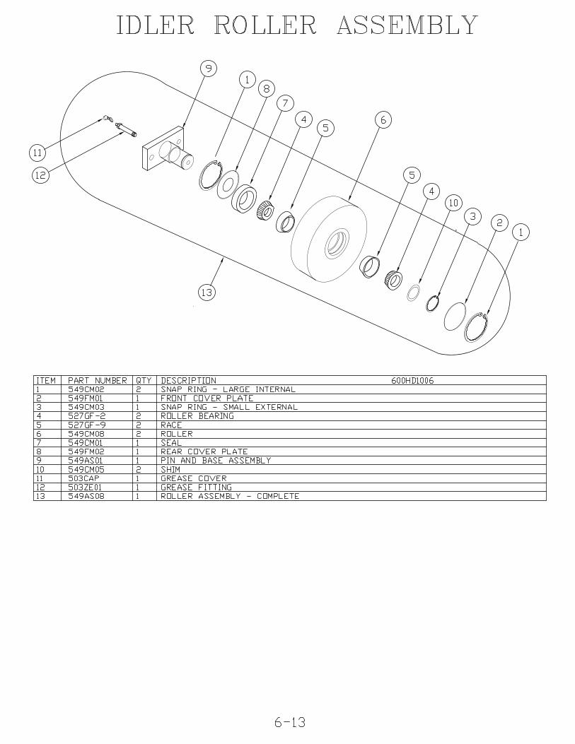
There are four 3 ½” steel rollers and four 8” poly rollers that support and guide theconveyor belt on the 600HD. The small rollers are used to support the conveyorchains. Two of the large rollers support and guide the conveyor belt over the frontof the bucket and the other two large rollers turn the belt at the bottom of themachine directing the belt toward the front main shaft and providing a surface offour rows of tines that clean the sand. The internal components are the same for allrollers. Look for any wear on the outside diameter/working surface of the roller. Onthe metal rollers there will be grooves from the contact with the conveyor chains. Ifthere are flats on the metal roller it must be replaced. To check for wear, loosen theconveyor belt by backing off the adjusting bolts located on each side under the topshaft take up bearings. Take the weight off of the roller you are inspecting. Checkfor any wobbling or play. If there is play the bearings are worn but can be adjusted.
To Adjust The Idler Rollers:
Shims are used to compensate for wear. Remove the bearing from the machine.Remove the external retaining ring and cover from the roller. Clean the greaseaway from the pin and retaining ring. Remove the retaining ring off of the pin. Addshim(s) as necessary, replace retaining ring and recheck for play. Repeat until theroller is tight on the pin. The rollers ride on tapered roller bearings. The bearingswill wear out prematurely if not adjusted for wear.
CHAIN CASE SPROCKETS AND CHAIN
The drive chain sprockets and chain will wear with use and need to be adjustedperiodically. Remove chain case cover and check chain tightness. There should be½” play in the chain, midway between the sprockets. Check the condition of theteeth of the sprockets. If they are worn down to half their original thickness, theyshould be replaced. The chain should be replaced if the sprockets are replaced.
8
To Adjust the Chain Case Drive Chain: Loosen the take up bolt and nut awayfrom the motor base plate. Slightly loosen the two motor mount bolts to allow themotor to slide. Tighten the take up bolt until there is ½” play in the drive chain.Retighten the motor mount bolts and the take up nut. Recheck the chain for correcttension. Only use dry film lubricant on the chain. Do not use grease or oil that willattract sand and shorten the life of the components.
SKID SHOES
There are two skid shoes located underneath the conveyor belt on each side and onthe inside of the side frame. There are wear blocks on each end of the conveyorbelt channels that ride on the skid shoes. The skid shoes prevent the belt fromsagging while elevating picked up debris on its way to the hopper. The skid shoesare made of an abrasion resistant material and must be replaced when they weardown to a thickness of 1/8”. Inspections should be made every month to monitorthe wear.
To Remove the Skid Shoes: Open the side door/guard. Tighten the conveyor beltfully to take the weight off of the skid shoes. Do this on each side of the machine.Loosen and remove the two ½” bolts that hold each skid shoe to the side framearms. Note the way that the angles/brackets of the skid shoes are situated inrelation to the side frame arms. Pry the skid shoes out toward the center of themachine. Replace with new skid shoes and fasteners. The skid shoes should sitdown flush on the side frame arms that they fasten to. A clamp may be needed tohold the skid shoes down when refastening to insure that they are flat on the arms.Slightly loosen the conveyor belt until there is one-inch play midway between thelarge 8” rollers.
HYDRAULIC COMPONENTS
Cylinders
The large and small cylinders are of similar design. They are single actingcylinders. Hydraulic pressure from the towing vehicle raises the cylinders and theweight of the bucket and gravity lowers them. Check for hydraulic leaks. There areseal kits to repair leaking cylinders. A WD-40 type penetrate can be used to preventthe seals from drying out when the machine sits for the off-season and also tolubricate the rods when first operating a machine after it has sat for a period of time.Clean the breathers to improve airflow in and out of the cylinders.
To Replace the Cylinder Seals: Power wash or clean the cylinder before removingit from the machine. Remove hose from cylinder. Remove breather from cylinder.Place the base of the cylinder in a vice and position the cylinder horizontally. Use abar through the piston rod hole to pull out the piston and piston rod assembly.Small cylinder – Have someone compress the retaining ring at the top of thecylinder while you pull the gland and rod assembly out of the cylinder. If theretaining ring is rusted it is advisable to use penetrating oil to clean up the ring andadjoining area. The retaining ring ends must touch in order to disassemble. Pullout as straight as possible.
9
Large Cylinder - Unscrew the top with a spanner wrench. Remove the rod/pistonassembly. Never try to slide the gland over the end of the piston rod. To cleangland, remove nut on bottom of piston rod and disassemble form that side.
Before removing seals, wipers, and o-rings, take note of their orientation in thepiston and gland. When replacing felt wipers, make sure they have been saturatedin oil. Coat all surfaces in oil before reassembly.
WHEELS SPINDLES AND AXLES
To check for play in the spindle/hubs, elevate the wheels off of the ground andcheck for play or looseness on the spindles. It is easier to determine if adjustmentis necessary when the tire/wheel is off the hub. If there is excessive play thebearing and races should be inspected for damage.
To Adjust Wheel Hubs: Remove the buddy hub/grease reservoir from the end ofthe hub. Clean away the grease. Remove the cotter pin. Tighten the castle nutassembly until the play is gone. Reinsert the cotter pin and grease reservoir. Thereis a blue collar on the grease reservoir that extends out when grease is added. Addgrease to the reservoir until the blue collar extends out. Check for tightness of thewheel cone nuts. They should be tightened to 95 ft/lbs. Wheels should be inflatedto 18 PSI.
TINE REPLACEMENTReplace tines as they break. Your machine can clean effectively with 20 or 30 tinesmissing; however, it is advisable to replace them soon after they break. When atine is broken, the work it would normally do picking up material is transferred to theadjacent tines. This will overwork them and, in turn, shorten their life. Neveroperate your machine with more than 50 broken tines.
The most convenient location for removing and replacing tines on the conveyor beltis at the back of the machine with the bucket raised and secured with the safetysupport. Never work on the machine without the safety support in place.
Tools recommended: Safety Support is REQUIRED! Impact gun or ratchet, 6"socket extension and 9/16" socket (6 point), large flat blade screwdriver, 9/16"combination wrench, drive torque wrench.
Position the belt. Rotate the conveyor belt slowly and stop it when the row on whichyou are going to replace the tines is at the top, back of the machine and parallel tothe ground.
Loosen conveyor bolts (SIX REVOLUTIONS MAXIMUM). Bolts on both sides ofany tine must be loosened in order to remove and replace the tine. The center boltsare secured by wing nuts that will fall to the inside of the belt if the bolts areloosened more than 6 turns. Marking the side of the 9/16" socket with a brightcolored line will allow you to count the revolutions while loosening a bolt. If a tine is
10
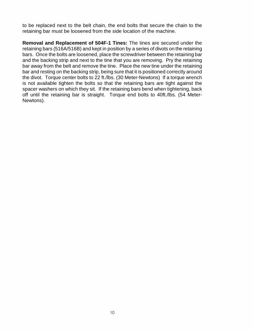
to be replaced next to the belt chain, the end bolts that secure the chain to theretaining bar must be loosened from the side location of the machine.
Removal and Replacement of 504F-1 Tines: The tines are secured under theretaining bars (516A/516B) and kept in position by a series of divots on the retainingbars. Once the bolts are loosened, place the screwdriver between the retaining barand the backing strip and next to the tine that you are removing. Pry the retainingbar away from the belt and remove the tine. Place the new tine under the retainingbar and resting on the backing strip, being sure that it is positioned correctly aroundthe divot. Torque center bolts to 22 ft./lbs. (30 Meter-Newtons) If a torque wrenchis not available tighten the bolts so that the retaining bars are tight against thespacer washers on which they sit. If the retaining bars bend when tightening, backoff until the retaining bar is straight. Torque end bolts to 40ft./lbs. (54 Meter-Newtons).
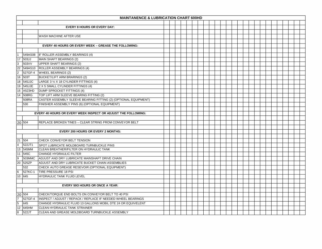
WASH MACHINE AFTER USE
1 549AS08 8" ROLLER ASSEMBLY BEARINGS (4)17 503JJ MAIN SHAFT BEARINGS (2)3 503VV UPPER SHAFT BEARINGS (2)22 549AS10 ROLLER ASSEMBLY BEARINGS (4)2 527GF-4 WHEEL BEARINGS (2)16 503T BUCKET/LIFT ARM BRARINGS (2)18 545JJC LARGE 3 ½ X 18 CYLINDER FITTINGS (4)19 545JJE 2 X 5 SMALL CYLINDER FITTINGS (4)15 A523HD DUMP SPROCKET FITTINGS (4)14 508RG TOP LIFT ARM SLEEVE BEARING FITTING (2)
20 504 REPLACE BROKEN TINES – CLEAR STRING FROM CONVEYOR BELT
21 504 CHECK CONVEYOR BELT TENSION4 522JT1 SPOT LUBRICATE MOLDBOARD TURNBUCKLE PINS13 545MM CLEAN BREATHER/FILTER ON HYDRAULIC TANK11 545C CHANGE HYDRAULIC FILTER9 503MMC ADJUST AND DRY LUBRICATE MAINSHAFT DRIVE CHAIN20 525ZP ADJUST AND DRY LUBRICATE BUCKET CHAIN ASSEMBLIES
532 CHECK AUTO GREASE RESEVOIR (OPTIONAL EQUIPMENT)6 527KC-1 TIRE PRESSURE 18 PSI10 645 HYDRAULIC TANK FLUID LEVEL
20 504 CHECK/TORQUE END BOLTS ON CONVEYOR BELT TO 40 PSI7 527GF-4 INSPECT / ADJUST / REPACK / REPLACE IF NEEDED WHEEL BEARINGS5 645 CHANGE HYDRAULIC FLUID 13 GALLONS MOBIL DTE 24 OR EQUIVELENT12 645HM CLEAN HYDRAULIC TANK STRAINER8 522JT CLEAN AND GREASE MOLDBOARD TURNBUCKLE ASSEMBLY
MAINTANENCE & LUBRICATION CHART 600HD
EVERY 50O HOURS OR ONCE A YEAR:
EVERY 8 HOURS OR EVERY DAY:
EVERY 40 HOURS OR EVERY WEEK – GREASE THE FOLLOWING:
EVERY 40 HOURS OR EVERY WEEK INSPECT OR ADJUST THE FOLLOWING:
EVERY 200 HOURS OR EVERY 2 MONTHS:
9
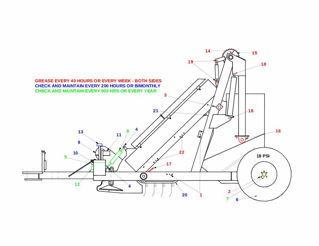
GREASE EVERY 40 HOURS OR EVERY WEEK - BOTH SIDES
CHECK AND MAINTAIN EVERY 500 HRS OR EVERY YEARCHECK AND MAINTAIN EVERY 200 HOURS OR BIMONTHLY
13
18
811
3
21
4
19
14 15
18
16
510
12
18 PSI
4
17
22
12067
2
BARBER SURF RAKE®MODEL 600HD
SECTION 6 - PARTS CATALOG AND ORDERING
When Ordering Parts, please have the following information available.
1. Model and serial number of your SURF RAKE®.2. Part number, description and page number.3. Shipping and billing address.4. Method by which shipment is to be made.5. Full name of consignee.6. Catalog number of this parts book.