12
Operation Manual BOTTLE TOP BOTTLE TOP DISPENSER DISPENSER BOTTLE TOP DISPENSER

OperationManual
BOTTLE TOPBOTTLE TOPDISPENSERDISPENSERBOTTLE TOPDISPENSER

Page No.TABLE OF CONTENTS
Safety Instructions
Functions and Limitations of Use 2
Chemical Compatibility Table 3
Setting up the Dispenser 10
Operating Exclusions
3
Maintenance / Cleaning 14
Dis-assembling and assembling the dispenser for cleaning and servicing
Autoclaving
14
Troubleshooting 19
First Steps 10
Dispensing 11
Error Limits 12
17
3
Storage Conditions
Priming 11
User Calibration Procedure 13
Intended Use Of The Instrument 1
1

This instrument may sometimes be used with hazardous materials, operations and equipments.
It is beyond the scope of this manual to address all of the potential risks associated with its use
in such applications. It is the responsibility of the user of this instrument to consult and establish
appropriate safety and health practice and determine the applicability of regulatory limitations
prior to use.
Please read the following carefully!
Every user must read and understand this operating manual before operation.
Follow general instructions for hazard prevention and safety instructions e.g. wear protective
clothing, eye protection and gloves.
Observe all specifications provided by reagent manufacturers.
When dispensing inflammable media, make sure to avoid the built up of static charge,
e.g. do not dispense into plastic vessels do not wipe instruments with a dry cloth.
Use the instrument only for dispensing liquids, with strict regard to the defined limitations of
use and operating limitations. Observe operating exclusions. (see page 2)
If in doubt, contact the manufacturer or supplier.
Always use the instrument in such a way that neither the user nor any other person is
endangered. When dispensing, the discharge tube must always point away from you or
any other person. Avoid splashes. Only dispense into suitable vessels.
Never press down the piston when the discharge tube closure is attached.
Never remove the discharge tube while the dispensing cylinder is filled.
Reagents can accumulate in the cap of the discharge tube. Thus, it should be cleaned
regularly.
Never carry the mounted instrument by the cylinder sleeve or the valve block. Breakage or
loosening of the cylinder may also lead to personal injury from chemicals.
Never use force on the instrument. Use smooth gentle movements to operate the piston
upwards and downwards. Use only original manufacturer's accessories and spare parts.
Do not attempt to make any technical alterations. Do not dismantle the instrument any
further than is described in the operating manual.
1).
2).
3).
4).
5).
6).
7).
8).
9).
10).
11).
12).
Safety Instructions
The bottle top dispenser is designed for dispensing liquids directly from the reservoir bottle.
The instrument is calibrated according to the requirements of the DIN EN ISO 8655 – 5.
When the instrument is correctly used, the dispensed liquid comes into contact with only the
following chemically resistant materials:
PTFE, FEP and Borosilicate glass.
Functions and Limitations of Use
Limitations of use :
This instrument is designed for dispensing liquids, observing the following physical limits:
Use temperature from +15°C to +40°C (from 59°F to 104°F) of instrument and reagent
Vapor pressure up to max. 600 mbar. Aspirate slowly above 300 mbar, in order to prevent
the liquid from boiling.
2Kinematic viscosity 500 mm
2(dynamic viscosity [mPas] = kinematic viscosity [mm /s] x density [g/cm³])
Density: up to 2.2 g/cm³
Operating Limitations :
Liquids, which form deposits may make the piston difficult to move or may cause jamming (e.g.,
crystallizing solutions or concentrated alkaline solutions). If the piston becomes difficult to move,
the instrument should be cleaned immediately. (see page 14)
When dispensing inflammable media, make sure to avoid buildup of static charge, e.g.
do not dispense into plastic vessels, do not wipe instrument with a dry cloth.
The Dispenser is designed for general laboratory applications and complies with the relevant
standards, e.g. DIN EN ISO 8655. Compatibility of the instrument for a specific application
(e.g. trace material analysis, food sector etc.) must be checked by the user. Approvals for
specific applications, e.g. for production and administration of food, pharmaceuticals and
cosmetics are not available.
2
The Bottle Top Dispenser is a general purpose laboratory instrument intended for use in
laboratories for dispensing reagents and chemicals which are compatible with the
instrument. (see page 4)
Always check the instrument for visual damage before use.
If there is a sign of a potential malfunction (e.g. piston difficult to move, sticking valve or
leakage). immediately stop dispensing. Consult the 'Troubleshooting' section of this manual
and contact the manufacturer if needed. (see page 19)
Intended Use Of The Instrument
1
13).
14).

Store the instrument and accessories only in clean conditions in a cool and dry place. Storage
temperature: from – 20°C to +50°C (from – 4°F to 122°F)
Storage Conditions
Operating Exclusions
Never use with:
Liquids attacking FEP, PFA and PTFE (e.g. dissolved sodium azide*)
Liquids attacking borosilicate glass (e.g. hydrofluoric acid)
Hydrochloric acid > 40% and nitric acid >70% | Tetrahydrofuran | Trifluoroacetic acid
Explosive liquids (e.g. carbon disulfide)
Suspensions (e.g. of charcoal) as solid particles may clog or damage the instrument
Liquids attacking PP (cap)**
* Dissolved sodium azide permitted up to a concentration of max. 0.1%.
** Liquids attacking PP (cap)
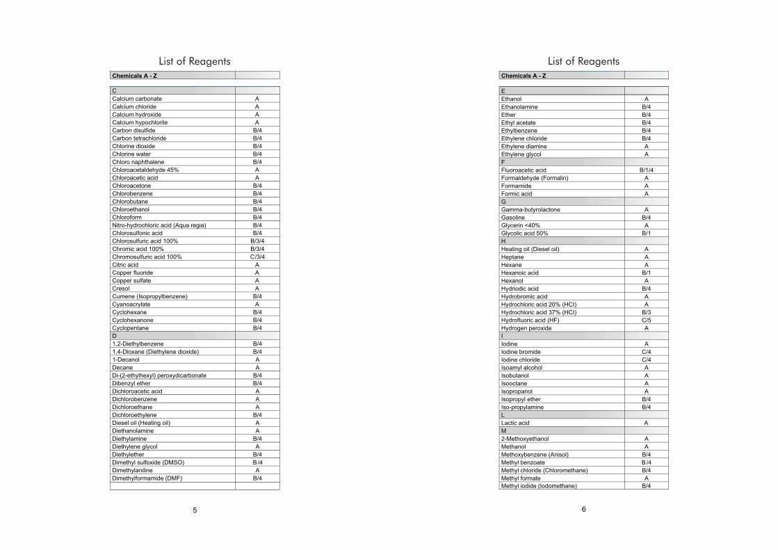
Chemicals from A to Z
The following list includes most frequently used chemicals. It provides useful information for the
safe and adequate use of the Dispenser. However, safety precautions and recommendations in
operating instructions must be followed carefully.
Code explanations
A = Good resistance B = Acceptable with limitations C = Not recommended
1 = Possible crystallisation - blockage or possible coating peeling
(do not let dry plunger/barrel together).
2 = Swell of plunger protection layer, possible peeling.
3 = Acid vapours (better resistance with lower concentration).
Do not leave instrument on bottle.
4 = Risk of damage, softening or discoloration of external parts through vapours.
Do not leave instrument on bottle.
5 = Chemical degradation of glass parts (plunger/barrel).
43
List of Reagents
Chemical Compatibility Table
65
List of Reagents List of Reagents

87
List of Reagents List of Reagents
(Fig. 1)
(Fig. 2)
(Fig. 3)
(Fig. 5)
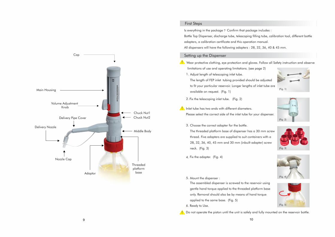
Cap
Delivery Nozzle
Delivery Pipe Cover
Chuck Nut1
Main Housing
Threaded platform
base
Volume Adjustment Knob
Middle Body
Chuck Nut2
Nozzle Cap
Adaptor
109
Wear protective clothing, eye protection and gloves. Follow all Safety instruction and observe
limitations of use and operating limitations. (see page 2)
1.
3.
4.
Adjust length of telescoping inlet tube.
The length of FEP inlet tubing provided should be adjusted
to fit your particular reservoir. Longer lengths of inlet tube are
available on request. (Fig. 1)
Do not operate the piston until the unit is safely and fully mounted on the reservoir bottle.
6.
First Steps
Is everything in the package ? Confirm that package includes :
Bottle Top Dispenser, discharge tube, telescoping filling tube, calibration tool, different bottle
adapters, a calibration certificate and this operation manual.
All dispensers will have the following adapters : 28, 32, 36, 40 & 45 mm.
Ready to Use.
5.
Fix the adapter. (Fig. 4)
2. Fix the telescoping inlet tube. (Fig. 2)
The assembled dispenser is screwed to the reservoir using
gentle hand torque applied to the threaded platform base
only. Removal should also be by means of hand torque
applied to the same base. (Fig. 5)
Mount the dispenser :
Choose the correct adapter for the bottle.
The threaded platform base of dispenser has a 30 mm screw
thread. Five adapters are supplied to suit containers with a
28, 32, 36, 40, 45 mm and 30 mm (inbuilt adapter) screw
neck. (Fig. 3)
Setting up the Dispenser
Inlet tube has two ends with different diameters.
Please select the correct side of the inlet tube for your dispenser.
(Fig. 4)

Locked UnlockedPosition1 Position2
Priming
Dispensing
Place a receiving vessel under the Dispenser's delivery nozzle. (Fig.7)
Remove the Nozzle Cap. (Fig.9)
Prime the unit with a few gentle up and down strokes, taking the piston right down to it's
lowest stop position and lifting it up. (Fig.8)
Repeat until a steady bubble free flow is visible in the barrel.
Hold the discharge tube orifice on the inner wall of a suitable
receiving vessel. (Fig. 7)
Gently lift the piston until the upper stop and then
depress piston slowly and steadily with minimal force
until the lower stop. (Fig. 8)
Wipe off the discharge tube against the inner wall of the
receiving vessel.
Reattach cap to discharge tube. (Fig. 9)
Error Limits related to the nominal capacity (= maximum volume) indicated on the instrument,
are obtained when instrument and distilled water are equilibrated at ambient temperature
(20°C/68°F). Testing takes place according to DIN EN ISO 8655-6 with a completely assembled
instrument and with uniform and smooth dispensing.
Error Limits
(Fig. 7)
(Fig. 8)
(Fig. 9)
1211
Volume Adjustment Knob (Fig. 6)
It is simple and easy to operate. There are two
positions of the knob as shown in Fig. 6 A :
- Position 1 : Locked Position
- Position 2 : Unlocked Position
Turn the Knob from Position 1 to Position 2 by
rotating it ANTICLOCKWISE as shown in Fig. 6 B1.
The slider is now loose and can be moved up
and down.
Set your desired volume by aligning the pointer
with the scale.
To lock the set volume, turn the Knob from
Position 2 to Position 1 by rotating it CLOCKWISE
as shown in Fig. 6 B2 .
Pointer
Slider
VolumeAdjustment
Knob
Setting the Volume : Follow these simple steps :
Lock to Unlock Position(Anti Clockwise)
Fig. 6 B2
Fig. 6 B1
Unlock to Lock Position(Clockwise)
Fig. 6 A
Fig. 6
0.25-2.5 ml 0.05 ml 0.0050.20.0150.6
0.5-5 ml 0.1 ml 0.0050.10.0250.5
1-10 ml 0.2 ml 0.0100.10.0500.5
2.5-30 ml 0.5 ml 0.0300.10.1500.5
5-60 ml 1.0 ml 0.0600.10.3000.5
10-100 ml 2.0 ml 0.1000.10.5000.5
Specifications
Vol.Range
IncrementCV
±% ± ml
Accuracy
± ml±%
0.0050.20.0150.6
0.0100.20.0300.6
0.0200.20.0600.6
0.0600.20.1800.6
0.1200.20.3600.6
0.2000.20.6000.6
(ISO 8655 )Specifications
Accuracy
± ml±% ±% ± ml
CV
Always wear protective gloves when touching the instrument or the bottle, especially when
using dangerous liquids. When mounted to a reagent bottle, always carry the instrument as
shown in the figure (5).
Never press down the piston when the cap is on. Avoid splashing the reagent.
The reagent can drip out from the discharge tube and cap. (Fig. 9)
Never press the piston without keeping the receiving vessel in place.

14
Maintenance / Cleaning
1. Procedure to dis-assemble the piston:
Pull the cap outwards to expose the Calibration Nut.
(Fig. 13)
The Dispenser should be cleaned in the following situations :
Immediatley when the piston is difficult
to move.
Before changing the reagent.
Prior to long term storage.
Prior to dismantling the instrument.
All maintenance should be carried out wearing suitable eye protection and protective
clothing. If in doubt, consult your safety officer.
Make sure that the Dispenser is completely empty.
Place the instrument into an empty sink together with its reservoir.
Unscrew the threaded platform base from the reservoir and lift the dispenser's intake
tube carefully out of the reservoir, whilst tapping it against the reservoir's aperture to
shake off any droplets from the intake tube.
Hold the dispense nozzle over the aperture of the reservoir and apply gentle piston
strokes in order to return any contents into the reservoir.
Empty the instrument completely and flush thoroughly with distilled water.
If the piston barrel is still not completely clean, you need to dis-assemble the dispenser.
1.
2.
3.
4.
5.
6.
Prior to autoclaving.
Prior to changing the valve.
Regularly when using liquids which form
deposits (e.g. crystallizing liquids).
Regularly when liquids accumulate in the cap.
Refer Dis-assembling procedure given below.
(Fig. 13)
Dispenser has been laboratory calibrated at its nominal volume. However, due to changes in
environmental conditions and the viscosity of the media which you dispense, we recommend
gravimetric testing every 3-12 months. Gravimetric volume testing according to DIN EN ISO 8655-6
(for measurement conditions, see 'Error Limits', page 13) is performed as follows:
Re-Calibrate :
Set the Dispenser to the nominal volume or any other
volume which is most commonly used by you. (Fig. 10)
Follow the common rules for calibration used in statistical
quality control (ISO 8655/2). Set the volume and
dispense five full volumes of distilled water at 20°C on
Electronic Balance to establish the actual mean volume of
liquid dispensed. If the gravitational average result varies
from the volume displayed, you should re-calibrate the
Dispenser.
1.
2.
Using the calibration tool, turn the
calibration nut clockwise to reduce the
volume and anticlockwise to increase
the volume. Repeat this procedure
till the desired volume is achieved on the
electronic balance. (Fig. 12)
3.
For re-calibration pull the cap
outwards to expose the Calibration nut. (Fig. 11)
User Calibration Procedure
(Fig. 10)
(Fig. 11)
(Fig. 12)
Dis-assembling and assembling the dispenser for cleaning and servicing

After unscrewing pull out the shaft. (Fig. 15)
Unscrew the Calibration Nut with the
help of calibration tool to dis-assemble
the Piston and shaft out of the main
housing. (Fig. 14)
Rinse the piston and shaft with deionized water. (Fig. 16)
Clean the cylinder with a bottle-brush. If necessary
carefully remove deposits at the edge of the glass
cylinder. (Fig. 17)
Then flush all the parts of the instrument with deionized
water. (Fig. 18)
Insert the piston completely into the cylinder and then
reassemble the instrument using the calibration tool
by screwing back the piston. (Fig. 19)
(Fig. 15)
(Fig. 16)
(Fig. 17)
(Fig. 18)
(Fig. 19)
16
Snap back the cap to complete the assembly.
3. Procedure to dis-assemble the DELIVERY PIPE
and VALVE MANIFOLD.
Remove the delivery pipe cover by•
pulling it upwards from the slot. (Fig.24)
Unscrew and remove the delivery pipe. (Fig.25)•
Unscrew the chuck Nut. (Fig.26)•
2. Procedure to dis-assemble the BARREL
Unscrew the Calibration using the•
special tool provided with the
instrument. (Fig.14)
Remove the Barrel Cap.(Fig.13)•
Lift the upper housing to expose the•
Barrel and cover. (Fig20)
Unscrew Chuck Nut 1 and remove Barrel cover. (Fig. 21)•
Glass Barrel in now exposed.•
Gently pull the barrel upwards to •
detach it from the Valve Manifold. (Fig.22)
Barrel has been dis-assembled for cleaning. (Fig.23)•
(Fig. 14)
(Fig. 20)
(Fig. 21)
(Fig. 22)
Glass Barrel
(Fig. 23)
Delivery Pipe Cover
(Fig. 24)
Delivery Pipe
(Fig. 25)
Chuck Nut 2
(Fig. 26)
• Remove Chuck Nut 2 and pull out the
valve manifold. (Fig.27)
(Fig. 27)Valve Manifold.
15
After unscrewing pull out the shaft. • (Fig. 15)

18
Autoclaving
Dis-assembling for Autoclaving :
This instrument is autoclavable at 121° C ) (250° F) 1 bar absolute (15 psi)
with a holding time of at least 15 minutes.
After unscrewing pull out the shaft. (Fig. 30)
Unscrew the Calibration Nut with the
help of calibration tool to dis-assemble
the Piston and shaft out of the main
housing. (Fig. 29)
This is the piston-shaft sub-assembly.
(Fig. 31)
Note : Only the piston needs to be removed for autoclaving the instrument.
Pull the cap outwards to expose the Calibration Nut.
(Fig. 28)
Re-assembling after Autoclaving :
0Autoclave the two sub-assemblies at 121 C and
15 psi pressure for 10-15 mins. (Fig. 32)
Dispenser is now ready for use.
No Re-calibation is required after autoclaving.
However, a quick calibration check is recommended.
(Fig. 35)
Insert the piston completely into the cylinder and then
reassemble the instrument use in the calibration tool
by screwing back the piston. (Fig. 33)
Snap back the cap to complete the assembly.
(Fig. 34)
(Fig. 35)
(Fig. 34)
(Fig. 33)
(Fig. 32)
17

Troubleshooting
Piston Difficultto move
Formation of crystals, dirty Stop dispensing immediately.Loosen piston with circularmotion, but do not disassemble.Follow all cleaning instructions.(see page 14 )
Dispensing notpossible
Blocked Dispensenozzle
Discharge valve stuck
Disassemble the dispensenozzle and flush throughwith distilled water. Clean Unit by immersing valveassembly in distilled water.(see page 14)
Air bubbles appearin the Instrument
Reagent with high vaporpressure has been drawnin too quickly
The instrument has notbeen primed
Filling tube is loose or damaged
Slowly draw in reagent.
Liquid reservoir is empty
the tube at the upper end and thenre-connect it or replace filling tube.
Too fast filling action Fill and dispense slowly.
Leaking Piston Clean Piston. (see page 14)If problem persist replacepiston.
Leaking discharge valve Clean by flushing throughlywith distilled water.(see page 14)
Prime the instrument.(see page 11)
Push the filling tube on firmly.if necessary cut off approx. 1 cm of
Refill reservoir and prime unit.
Wrong Dispenser Volume
Instrument not calibrated Follow steps of user calibration.(see page 13)
Barrel does not fill with liquid
Inlet tube not fittedfirmly
Connect inlet tube correctly.(see page 10, Fig. 2)
Filling Not Possible Volume adjustment toMinimum setting
Set to required volume.(see page 11)
Trouble Possible Cause Solution
19


