1 | Page B.Tech. Degree in ELECTRICAL AND ELECTRONICS ENGINEERING SYLLABUS FOR CREDIT BASED CURRICULUM (With effect from 2017-2018 onwards) DEPARTMENT OF ELECTRICAL AND ELECTRONICS ENGINEERING NATIONAL INSTITUTE OF TECHNOLOGY PUDUCHERRY KARAIKAL – 609 609
Transcript
1 | P a g e
B.Tech. Degree in
ELECTRICAL AND ELECTRONICS ENGINEERING
SYLLABUS FOR CREDIT BASED CURRICULUM (With effect from 2017-2018 onwards)
DEPARTMENT OF ELECTRICAL AND ELECTRONICS
ENGINEERING
NATIONAL INSTITUTE OF TECHNOLOGY PUDUCHERRY KARAIKAL – 609 609
2 | P a g e
2 YEAR - SEMESTER III
S.No Code Course of Study L T P C
1. MA207 Transforms and Probability Theory 3 0 0 3
2. EE201 Circuit Theory 3 1 0 4
3. EE203 Electromagnetic Theory 3 0 0 3
4. EE205 Electrical Machines I 3 1 0 4
5. EE207 Signals and Systems 3 1 0 4
6. EE209 Digital Logic Circuits 3 0 0 3
7. EE211 Electrical Machines Lab I 0 0 3 2
8. EE213 Circuits and Digital Electronics Lab 0 0 3 2
3. EE204 Transmission and Distribution of Electrical Energy 3 0 0 3
4. EE206 Analog Electronics Circuits 3 1 0 4
5. EE208 Control Systems 3 1 0 4
6. EE210 Microprocessor and Microcontroller 3 0 0 3
7. EE212 Electrical Machines Lab II 0 0 3 2
8. EE214 Analog Electronics Circuits Lab 0 0 3 2
Total Credits 25
3rd YEAR – V SEMESTER
Sl.No Code Course of Study L T P C
1. EE301 Power System Analysis 3 1 1 4
2. EE303 Measurement and Instrumentation 3 0 0 3
3. Departmental Elective 1 3 0 0 3
4. Departmental Elective 2 3 0 0 3
5. Global Elective 1 3 0 0 3
6. EE305 Control and Instrumentation Lab 0 0 3 2
7. EE307 Microprocessor and Microcontroller Lab
0 0 3 2
Total Credits 20
3 | P a g e
3rd YEAR – VI SEMESTER
Sl. No Code Course of Study L T P C
1. HM302 Professional Ethics and Human Values
2 0 0 2
2. EE302 Power Electronics 3 0 0 3
3. Departmental Elective 3 3 0 0 3
4. Departmental Elective 4 3 0 0 3
5. Global Elective 2 3 0 0 3
6. EE304 Power Electronics Lab 0 0 3 2
7. EE306 Power System Simulation Lab 0 0 3 2
Total Credits 18
4th YEAR – VII SEMESTER
S.No Code Course of Study L T P C
1. HM401 Industrial Economics and Management
3 0 0 3
2. Global Elective 3 3 0 0 3
3. Departmental Elective 5 3 0 0 3
4. Departmental Elective 6 3 0 0 3
5. Departmental Elective 7 3 0 0 3
6. EE403 Project Phase I 0 0 - 2
Total Credits 17
4th YEAR – VIII SEMESTER
S.No Code Course of Study L T P C
1. Departmental Elective 8 3 0 0 3
2. Departmental Elective 9 3 0 0 3
3. Departmental Elective 10 3 0 0 3
4. Departmental Elective 11 3 0 0 3
5. EE402 Project Phase II 3 0 - 4
Total 16
4 | P a g e
DEPARTMENTAL ELECTIVES SUBJECTS
ELECTIVES OFFERED AT V SEMESTER (2/4)
S.No Code Course of Study L C
1. EE501 Electrical Machine Design 3 3
2. EE503 Power Plant Engineering 3 3
3. EE505 Modern Control Theory 3 3
4. EE507 High Voltage Engineering 3 3
ELECTIVES OFFERED AT VI SEMESTER (2/4)
S.No Code Course of Study L C
1. EE502 Power system operation and Control 3 3
2. EE504 Digital Logic Design using VHDL 3 3
3. EE506 Digital Control Systems 3 3
4. EE508 Special Machines 3 3
ELECTIVES OFFERED AT VII SEMESTER(3/5)
S.No Code Course of Study L C
1. EE509 Solid State drives 3 3
2. EE511 Power system Protection and Switchgear 3 3
3. EE513 Intelligent Techniques 3 3
4. EE515 Biomedical Instrumentation 3 3
5. EE517 Utilization of Electrical Engineering 3 3
ELECTIVES OFFERED AT VIII SEMESTER(4/6)
S.No Code Course of Study L C
1. EE510 Power System Restructuring 3 3
2. EE512 Flexible AC Transmission Systems 3 3
3. EE514 Static Relays 3 3
4. EE516 Power Quality 3 3
5. EE518 EHVAC and HVDC Transmission System 3 3
6. EE520 Virtual Instrument Design 3 3
5 | P a g e
GLOBAL ELECTIVES OFFERED BY EEE DEPARTMENT TO OTHER DEPARTMENT
S.No Code Course of Study L C
1. EE1001 Industrial Electronics 3 3
2. EE1002 Soft Computing Techniques 3 3
3. EE1003 Power Generation Systems 3 3
4. EE1004 Electrical and Electronics Measurement 3 3
5. EE1005 Medical instrumentation 3 3
6. EE1006 Applied Electrical and Electronics Engineering 3 3
6 | P a g e
DETAILED SYLLABUS
7 | P a g e
I Year
EE101 BASICS OF ELECTRICAL AND ELECTRONICS ENGINEERING COURSE OBJECTIVES To enable the students to gain knowledge about the fundamentals of Electrical and Electronics engineering. UNIT I: Definition of Voltage, Current, Power & Energy, circuit parameters, Ohm’s law, Kirchoff’s law. Series and Parallel DC circuits. Concepts of AC Circuits- rms value, average value, form and peak factors. Simple RL, RC and RLC series and parallel circuits Concept of real and reactive power – Power factor. Introduction to three phase systems - types of connections, relationship between line and phase values. UNIT II: Definition of mmf, flux and reluctance, leakage flux, fringing, magnetic materials and B-H relationship. Faraday’s laws of electromagnetic induction. Basic Working principle and construction of electrical Machines. Introduction to electrical measuring instruments. UNIT III: Types of wiring-staircase & corridor wiring, wiring accessories. Basic safety measures at home and industry- earthing. Electrical tariff, energy audit and importance of energy saving. Simple layout of generation-various energy resources, transmission & distribution of power. The Laws of Illumination-Electric lamps. UNIT IV: Semiconductor: Energy band diagram, Intrinsic and Extrinsic semiconductors, PN junction diodes and Zener diodes - characteristics. Transistors: PNP and NPN transistors - theory of operation - Transistor configurations -characteristics - comparison. Special semiconductor devices: FET - SCR - LED - V I characteristics - applications. UNIT V: Digital Fundamentals: Number systems - Boolean Theorems - DeMorgan's Theorem - Logic gates -Implementation of Boolean Expression using Gates. Integrated Circuits: IC fabrication - Monolithic Technique, Introduction to Operational Amplifier. TEXT BOOKS
1. Muthusubramanian.R, Salivahanan.S, Muraleedharan.K.A, "Basic Electrical, Electronics and Computer Engineering", Tata McGraw - Hill, 1999.
2. Smarajit Ghosh, “ Fundamentals of Electrical and Electronics Engineering”, PHI, 2nd Edition,
2010. REFERENCE BOOKS
8 | P a g e
1. Thomas L. Floyd "Electronic devices", Addison Wesley Longman (Singapore) Pvt. Ltd., 2. 5th Edition. 3. Kothari D P and Nagrath I J, Basic Electrical Engineering , Tata McGraw Hill,1991. 4. Mehta V K ,Principles of Electronics S Chand & Co,1980. 5. Mithal G K, Electronic Devices and Circuits, Khanna Publications, 1997. 6. Kalsi H S, "Electronics Instrumentation", ISTE publication, 1995. 7. Huges, “Electrical and Electronics Technology”, Pearson, 10th Edition, 2011.
COURSE OUTCOMES Students will be able to
1. Understand the basics of electric circuits. 2. Understand the basics of electromagnetic laws. 3. Understand the basic working principle of DC and AC machines. 4. Understand the concepts of power generation, energy saving, illumination, electric lamps,
protective devices for safety. 5. Understand the basic operation and characteristics of electron devices.
Understand the fundamentals of digital electronics and integrated circuits.
9 | P a g e
SEMESTER III
10 | P a g e
MA207 TRANSFORMS AND PROBABILITY COURSE OBJECTIVES To enable the students to gain knowledge about transforms, partial differential equations and probability.
Unit I: Fourier series: Expansion of a function in Fourier series for a given range - Half range sine and cosine expansions. UnitII: Fourier Transforms: Complex form of Fourier series- Fourier sine and cosine transformations - simple illustrations. Finite Fourier sine and Cosine transforms. Unit III: Partial Differential Equations: Solutions of Wave equation, Heat equation and Laplace’s
equation by the method of separation of variables and their use in problems of vibrating string, one dimensional unsteady heat flow and two dimensional steady state heat flow. Unit IV: Two-dimensional steady state heat flow equation. Heat equation, Wave equation - Fourier series solution. Unit V: Definitions of Probability - Notion of sample space - Events - Basics of Combinatorial Analysis
- Posing Probability problems mathematically – Examples, Conditional Probability - Baye's Rule - Random variable - Probability mass function, Density function, Distribution Function - Bernoulli Trials - Binomial Distribution - Poisson Approximation - Poisson Distribution - Normal Distribution - Moment Generating Function.
Text Book
1. Erwyn Kreyszig, “Advanced Engineering Mathematics”, John Wiley and Sons, 10th Edition, 2011.
2. Gupta.S.C and Kapoor.V.K, “Fundamentals of Mathematical Statistics”, Sultan Chand, 2000. 3. W. FELLER, An Introduction to Probability Theory and its Applications, Vol. 1, Wiley Eastern,
New Delhi.
Reference Book
1. Grewal.B.S, “Higher Engineering Mathematics”, Khanna Publications, 42nd Edition, 2013. 2. K. S. TRIVEDI, Probability and Statistics with Reliability and Queueing and Computer Science
Applications, Prentice Hall of India, 1988.
11 | P a g e
3. O. ALLEN, Introduction to Probability, Statistics and Queueing Theory with Computer Science Applications, Academic Press, 2006 reprint.
COURSE OUTCOMES Students will be able to
1. Understand the Fourier series, Fourier transform. 2. Understand the partial differential equations and their solution. 3. Understand the probability theory.
12 | P a g e
EE201 CIRCUIT THEORY
COURSE OBJECTIVES The objective of this course is
To provide basic knowledge of AC and DC circuits To familiarize the concepts and terminologies of series & parallel resonance circuits and tuned
circuits among the students To motivate the students for analyzing three phase 3 wire, three phase 4 wire circuits and the
concept of power measurement. To impart knowledge on finding the transient response of series and parallel AC and DC
circuits. Unit I: Independent and dependent voltage and current sources – R, L, C components – self and mutual inductances - Series and Parallel connection – mesh, node and loop analysis – network theorems – source transformation- star-delta transformation. Unit II: Introduction to AC circuits – active and reactive power- phasor analysis –Network Theorems–
Resonance in series and parallel circuits. Unit III: - Time response of RL, RC and RLC circuits for step input - coefficient of coupling - dot convention- analysis of coupled circuits. Unit IV: Three phase systems – symmetrical components – measurement of power in three phase systems -Three - phase star and delta circuits with balanced and unbalanced loads - power measurements-power factor calculations.
Unit V: Characterization of two port networks in terms of Z,Y,H and T parameters – networks equivalents – relations between network parameters –transfer function of terminated two port networks. TEXT BOOKS
1. Hayt.W.H and Kemmerly.J.E, “Engineering Circuit Analysis”, Tata McGraw Hill, New York, 7th Edition, 2007.
2. Joseph. A. Edminister, “Electric Circuits - Schaum's outline series”, Tata McGraw Hill International, 5th Edition, 2003.
REFERENCE BOOK 1. Charles K. Alexander and Matthew N. O. Sadiku, “Fundamentals of Electric Circuits”,
13 | P a g e
Tata McGraw Hill Companies, 5th Edition, 2013. COURSE OUTCOMES Students will be able to
1. Understand the basic laws, mesh current, nodal voltage, voltage and current division, source transformation and star/delta transformation methods for solving circuit problems.
2. Understand the basic network theorems used for solving networks with both DC and AC inputs. 3. Understand the concepts and terminologies behind series & parallel resonance circuits and
tuned circuits. 4. Understand the analysis of three phase 3 wire and 4 wire circuits with star and delta
connected loads and the concept of power and power factor measurement in three phase circuits.
5. Understand the transient response of series and parallel RL, RC and RLC circuits using Laplace transforms for both DC & AC inputs.
14 | P a g e
E203 ELECTROMAGNETIC THEORY
COURSE OBJECTIVES The objective of this course is to Understand the basic concepts of electric and magnetic fields. Understand the concept of conductors, dielectrics, inductance and capacitance Gain knowledge on the nature of magnetic materials. Understand the concept of static and time varying fields. Unit I: Sources and effects of electromagnetic fields – Vector fields – Different co-ordinate systems –
Vector calculus – Gradient, Divergence and Curl – Divergence theorem – Stoke’s theorem. Unit II: Coulomb’s Law – electric field intensity – Field due to point and continuous charges – Gauss’s law and its applications – electrical potential – Electric field and equipotential plots – electric field in free space, conductors, dielectric – dielectric polarization. Electric field in multiple dielectrics – boundary conditions, Poisson’s and Laplace’s equations –Capacitance – Energy density – Dielectric
strength – Applications. Unit III: Lorentz Law of force, magnetic field intensity – Biot – Savart Law – Ampere’s Law – Magnetic field due to straight conductors, circular loop, infinite sheet of current – Magnetic flux density (B) – B in free space, conductor, magnetic materials. Magnetization - Magnetic field in multiple media – Boundary conditions – Scalar and vector potential – Magnetic force – Torque – Inductance – Energy
density – Magnetic circuits – Applications. Unit IV: Faraday’s law, induced emf – transformer and motional EMF, Maxwell’s equations (differential and integral forms)- Displacement current – Applications - Relation between field theory and circuit theory. Unit V: Generation – electromagnetic wave equations – Wave parameters; velocity, intrinsic impedance, propagation constant – Waves in free space, lossy and lossless dielectrics, conductors –
skin depth, Poynting Theorem-Reflection and Refraction.
TEXT BOOKS 1. Matthew. N.O. Sadiku, “Elements of Electromagnetics”, Fourth Edition, Oxford
University Press, Fifth Edition 2010. 2. Ashutosh Pramanik, “Electromagnetism – theory and application,” Prentice Hall of India
15 | P a g e
Private Ltd., New Delhi, 2nd edition, 2008. 3. K.A.Gangadhar, "Field theory", Khanna publishers, New Delhi,15th edition,2004.
REFERENCE BOOKS
1. William H.Hayt and John A Buck “Engineering Electromagnetics”, 7th Edition, Tata McGraw Hill Publishing Company Limited, New Delhi, 2006.
2. Edminister.J.A, Schaum’s Outlines “Theory and problems of Electromagnetics”, Tata Mc Graw Hill, 2nd Edition, Special Indian Edition 2006.
3. Guru and Hiziroghu “Electromagnetic field theory fundamentals”, Thomson Asia Pvt. Limited, 2010.
4. John D Kraus, Daniel A Fleisch “Electromagenetics with Applications”, Tata McGraw Hill 5th Edition, 2010.
COURSE OUTCOMES
1. An ability to apply knowledge of mathematics, science, and engineering. 2. An ability to identify, formulate, and solve engineering problems
16 | P a g e
EE205 ELECTRICAL MACHINES I COURSE OBJECTIVES The objective of this course is
To familiarize the constructional details, the principle of operation, prediction of performance, the methods of testing the transformers and three phase transformer connections.
To introduce the principles of electromechanical energy conversion in singly and multiply excited systems.
To study the working principles of electrical machines using the concepts of electromechanical energy conversion principles and derive expressions for generated voltage and torque developed in all Electrical Machines.
To study the working principles of DC machines as Generator and Motor, types, determination of their no-load/load characteristics, starting and methods of speed control of motors.
To estimate the various losses taking place in D.C. machines and to study the different testing methods.
Unit I: Basic magnetic circuit analysis - BH curve – BH loop - hysteresis and eddy current loss – iterative method of solving. Faradays law of Electromagnetic induction – Principle of Energy conversion- singly and doubly Excited magnetic field systems. Unit II: DC Generator – construction - lap and wave windings, classification, principle of operation, types – EMF equation – Characteristics - commutation - Armature reaction, Equivalent circuit, Parallel operation of Generators.
Unit III: DC motor – principle of operation, types – Torque equation – Electrical and Mechanical characteristics – starting – speed control – Various testing – Braking, Parallel operation of motors. - Losses in DC machines, Efficiency - Starting, speed control and braking of DC motors – Permanent magnet motors. Unit IV: Transformers – Construction, working principle, EMF equation, performance of transformer on
no load and loaded condition-Phasor diagrams- Equivalent circuit – efficiency, Losses, Voltage regulation -Tests on Transformer- parallel operation of transformer. Unit V: Auto-transformer-Three phase transformer – types of connections – Open Delta Connection-
17 | P a g e
Scott connections. Three-phase to single phase conversion. all day efficiency, Instrument Transformers – Current Transformer, Potential Transformer. Tap-changing and voltage control. TEXT BOOKS
1. Nagrath.I.J and Kothari.D.P, “Electrical Machines”, Tata McGraw Hill Education Private Limited, New Delhi, 4th Edition, 2010.
2. Sawhney.A.K, “ A course in Electrical machines Design”, Dhanpat Rai and Sons , New Delhi, 5th Edition, 1990.
REFERENCE BOOKS 1. Theraja B.L., Theraja A.K., “ A Textbook of Electrical Technology: Volume 2 AC and DC
Machines: AC and DC Machines - Vol. 2”, S. Chand, 23rd Edition, 2006. 2. Cotton.H, “Electrical Technology”, CBS Publishers, 7th Edition, 2005.
COURSE OUTCOMES
1. Students will know the constructional details ,working principle, control and applications of DC Machines
2. Students will know the constructional details and working principle of transformers. 3. Students will acquire the ability to :
i. Design and conduct experiments, as well as to identify, formulate and solve machine related problems.
ii. Analyze the performance of the DC Machines under various operating conditions using their various characteristics.
iii. Evaluate the performance of Transformers using phasor diagrams and equivalent circuits.
iv. Discuss electric and magnetic field interactions in electromechanical devices and machines
18 | P a g e
EE207 SIGNALS AND SYSTEMS COURSE OBJECTIVES The objective of this course is to introduce the concepts and techniques associated with the
understanding of signals and systems and to familiarize with techniques suitable for analyzing and synthesizing both continuous-time and discrete time systems which provides foundation for more advanced subjects like signal processing, system theory, control and robotics. Unit I: Introduction to signals and systems: Introduction to signals, classification of signals, basic continuous- time and discrete- time signals, step and impulse functions, transformation of independent variable. Introduction to systems, properties of systems, classification of systems, mathematical model for systems, normal form of system equations, initial conditions – Laplace transform – system transfer
function. Unit II: Impulse response of a physical system, introduction to convolution, system impulse response and convolution integral, numerical convolution. Sampling theorem, Z-transform, convergence of Z-transform, properties of Z-transform, inversion of Z-transform , evaluation of system frequency response, applications of Z-transform – bilinear transformation. Unit III: Representation of signals in terms of elementary signals, condition for orthogonality,
representation of signals by elementary sinusoids, Fourier series representation, power spectrum, Fourier Transform, system function, energy spectrum. Calculation of simple transforms, Discrete Fourier Transform (DFT), properties of Discrete Fourier Transform. Unit IV: Statistical Signal Analysis: Classification of random signals, auto correlation function, properties of auto correlation function, measurement of auto correlation function, application of
autocorrelation functions, cross correlation functions, properties of cross correlation functions, sum of random processes. Unit V: Spectral density, relation of spectral density to autocorrelation function. Auto correlation function of system output, cross- correlation between input and output, white noise, generation of pseudo-random binary noise, analysis of linear systems in time domain using white noise, mean and
mean square value of system output, analysis in the frequency domain.
19 | P a g e
TEXT BOOKS 1. Gabel.R.A and Robert.R.A, “Signals and Linear Systems”, 3rd Edition, John Wiley and
Sons, New York, 2009. 2. Oppenheim, Wilsky and Nawab, “Signals and Systems”, 2nd Edition, Prentice Hall, New
Delhi, 1997. 3. Chen.C.T, “Systems and Signal Analysis”, Oxford University Press, India, 3rd Edition,
2004, ISBN 100195156617.
REFERENCE BOOKS 1. Cooper.G.R and McGillem.C.D, “Probabilistic Methods of Signals and System
Analysis”, 3rd Edition, Oxford University Press, Cambridge, 2007. 2. Chesmond, Wilson and Lepla, “Advanced Control System Technology”, ISBN-
8176490326, Viva Books, India, 1998. 3. Ziemer R.E, Tranter W.H and Fannin D.R, “Signals and Systems”, 4th Edition,
Pearson Education Asia, Singapore, 1998. COURSE OUTCOMES On completion of this course the student will be able to: 1. Determine the mathematical representations of systems and analyse systems in order to calculate, estimate and classify their impulse, step, frequency response and evaluate their stability. 2. Determine the properties of continuous time domain signals using Laplace transform and discrete time signals using Z-transform and their transformation to treat a class of signals broader than what the Fourier transform can handle. 3. Classify and analyse the random/noise signals.
20 | P a g e
EE209 DIGITAL LOGIC CIRCUITS
COURSE OBJECTIVES The objective of this subject is to study Various number systems and to simplify the mathematical Expressions using Boolean Functions – simple problems. Implementation of combinational circuits Design of various synchronous and asynchronous circuits. Digital simulation techniques for development of application oriented logic circuit. Unit I: Review of Number systems - Complements - Subtraction using complements - Binary codes - Theorems of boolean algebra - Canonical forms - Logic gates, Simplification of Boolean functions-K
maps. Digital logic families: TTL, ECL, MOS-Comparison between the families. Unit II: Combinational Logic circuits-adders, subtractors - Multiplexers and demultiplexers - Code converters, comparators. Unit III: Sequential Logic-Flip flops - SR, JK, D and T flip flops - Level triggering and edge triggering - Excitation tables - Counters - Asynchronous and synchronous counters - Shift registers - Ring
counters. Unit IV: Design of Synchronous sequential circuits: Model Selection – State transition diagram –State synthesis table – Design equations and circuit diagram – State reduction technique. UNIT V : Asynchronous sequential circuits – Analysis – Problems with asynchronous sequential circuits – Design of Asynchronous sequential circuits-State transition diagram, Primitive table, State reduction, state assignment and design equations. PLA,PAL, Introduction to FPGA.
TEXT BOOKS
1. Morris Mano,M .'Digital logic and computer design', Prentice Hall of India, Ist Edition, 2008.
2. Donald D. Givone, “Digital Principles and Design”, Tata McGraw Hill, 2002. 3. Tocci R.J.,Neal S. Widmer, 'Digital Systems: Principles and Applications', Pearson
1. Floyd and Jain, “Digital Fundamentals”, Pearson Education, 10th Edition 2013, 2007. 2. Donald P. Leach , Albert Paul Malvino, Goutam Sha, “Digital Principles and
Applications”, Tata McGraw Hill, 6th Edition, 2007.
22 | P a g e
EE211 ELECTRICAL MACHINES I LAB
LIST OF EXPERIMENTS 1. Open circuit and load characteristics of DC shunt generator
2. Load characteristics of DC compound generator 3. Load test on DC shunt motor 4. Speed control of DC shunt motors 5. Swinburne's test 6. Open circuit and short circuit test on single phase transformer 7. Separation of no load losses in a single phase transformer
8. Sumpner's test 9. Load test on single phase transformer 10. Polarity test on transformer 11. Parallel operation of transformer
EE213 CIRCUITS AND DIGITAL ELECTRONICS LAB
LIST OF EXPERIMENTS 1. Verification of Circuit theorems 2. Study of flip flops 3. Study of encoders and decoders 4. Binary counter 5. Decade counter with decoder/driver and seven segment LED display 6. Ring counter 7. Design of sequential logic circuit 8. Design of combinational logic circuits 9. Electronic gain using bi-directional shift registers
23 | P a g e
SEMESTER IV
24 | P a g e
MA208 NUMERICAL METHODS FOR ELECTRICAL ENGINEERING COURSE OBJECTIVES To enable the students to gain knowledge about numerical methods. Unit I: Solution of linear system - Gaussian elimination and Gauss-Jordan methods – LU-
decomposition methods - Crout's method - Jacobi and Gauss-Seidel iterative methods sufficient conditions for convergence. Unit II: Numerical solution of algebraic and transcendental equations by Bisection method, Regula-Falsi method, Newton - Raphson’s method, muller method- Order of convergence.
Unit III: Curve fitting by the method of least squares. Fitting of Straight line, Second and higher order linear and nonlinear fit, exponential fit, etc…,. Weighted least squares approximation, linear Weighted least squares approximation, Non-linear weighted least squares approximation. Unit IV: Lagrange interpolation, Forward, backward and central differences, Newton’s forward and
backward interpolation formulae, Stirling and Bessel’s interpolation formulae, Newton’s divided difference formulae, Numerical differentiation at the tabulated points with forward backward and central differences. Unit V: Numerical Integration with Trapezoidal rule, Simpson’s 1/3 rule, Simpson’s 3/8 rule. Numerical solution of order ordinary differential equations with Taylor series method, Euler’s method,
modified Euler’s method, Runge-Kutta method of 4th orders for solving first order.
Text Books 1. Erwyn Kreyszig, “Advanced Engineering Mathematics”, John Wiley and Sons, 8th Edition,
2010. 2. Jain, MK., Iyengar, S.R., and Jain, R.K., Numerical Methods for Scientific and Engineering
Computation, Wiley Eastern, 1991.
25 | P a g e
3. Gerald, CF., and Wheatley, P.O., Applied Numerical Analysis, Mis. Addison Wesley, 1989. Reference Book
COURSE OUTCOMES Students will be able to apply numerical methods to solve problems in electrical engineering.
26 | P a g e
EE202 ELECTRICAL MACHINES II
COURSE OBJECTIVES To expose the students to the concepts of various types of AC Electrical Machines and
fractional KW motors Unit I: Concept of rotating flux - Poly phase Induction motors (machine)- construction, types, principle
of operation, slip, effect of slip on motor parameters – Torque equation- slip-torque characteristics-equivalent circuit - power flow diagram-testing of induction motor. Unit II: Circle diagram-Starting and speed control – Braking- double cage induction motor-crawling and cogging, induction generators - applications. Unit III: Alternators - construction, classification, application, non salient pole synchronous machine: working principle, EMF equation, distribution factor and pitch factor, armature reaction, equivalent
circuit, phasor diagram, calculation of synchronous reactance, performance indices, isolated and parallel operation of synchronous generator, testing, power angle characteristics, V-curve , parallel operation, load sharing, short circuit transient in synchronous machine. Salient pole synchronous machine: two reaction theory, determination of Xd and Xq. Unit IV: Synchronous motors - construction, principle and types - starting methods - phasor diagrams
-V and inverted V curves – Hunting. Unit V: Single phase induction motors – Rotating magnetic Vs alternating magnetic field - Double revolving field theory – Torque - speed characteristics – types – Reluctance motor– Two phase Servo motor– Stepper motors – Universal motor- linear induction motor - permanent magnet AC motor. TEXT BOOKS
1. Nagrath.I.J and Kothari.D.P, “Electrical Machines”, Tata McGraw Hill Education Private Limited, New Delhi, 4th Edition, 2010.
2. Irving L.Kosow, “Electric Machinery and Transformers”, Prentice Hall of India Private Ltd., New Delhi, 2nd Edition, Reprint 2007.
3. Sawhney.A.K, “ A course in Electrical machines Design”, Dhanpat Rai and Sons , New Delhi, 5th Edition, 1990.
27 | P a g e
REFERENCE BOOKS 1. Theraja B.L., Theraja A.K., “ A Textbook of Electrical Technology: Volume 2 AC and
DC Machines: AC and DC Machines - Vol. 2”, S. Chand, 23rd Edition, 2006. 2. Say M.G, “Performance and Design of Alternating Machines”, CBS Publishers and
Distributors, New Delhi, Reprint 2005. 3. Stephen J.Chapman, “Electric Machinery Fundamentals”, Tata McGraw Hill
International Edition, New Delhi, 4th Edition, 2005. COURSE OUTCOMES
1. Students will be aware of the constructional details, principle of operation of AC Machines and fractional kw motors.
2. Students will be able to understand and analyse the phasor diagrams and equivalent circuits of AC Induction and Synchronous Machines.
28 | P a g e
EE204 TRANSMISSION AND DISTRIBUTION OF ELECTRICAL ENERGY COURSE OBJECTIVES To impart knowledge
1. On the basics of transmission and distribution of power system. 2. For estimation of sag and tension. 3. For the Calculation of R, L and C of transmission line. 4. About Corona and its effects 5. For evaluating the performance of transmission line. 6. About insulators and cables and their grading. 7. Regarding bus bar arrangements in substation.
Unit I: Transmission line parameters – resistance, inductance and capacitance calculations - single phase and three phase lines – double circuit line - effect of earth on transmission line capacitance.
Unit II: Performance of transmission lines – regulation and efficiency – tuned power lines power flow through a transmission line – power circle diagrams, formation of corona – critical voltages – effect on line performance. Unit III: Mechanical design of overhead lines – line supports – insulators - voltage distribution in suspension insulators – string efficiency - testing of insulators stress and sag calculation – effects of wind and ice loading.
Unit IV: Underground cables – comparison with overhead line – types of cables – insulation resistance – potential gradient – capacitance of single core and three core cables. Unit V: Distribution systems – general aspects – Kelvin's Law, A.C. distribution – single phase and three phase - techniques of voltage control and power factor improvement, recent trends in transmission and distribution systems.
TEXT BOOKS
1. Wadhwa.C.L, “Electrical Power systems”, New Academic Science Limited Publishers, 2009.
2. Gupta.B.R, “Power System Analysis and Design”, Chand Publishing, 2005. 3. Cotton.H, “Transmission and Distribution of Electrical Energy”, ELBS, reprinted
edition, 2006.
29 | P a g e
REFERENCE BOOKS
1. Singh.S.N, “Electric Power Generation, Transmission and Distribution”, Prentice Hall of India Private Limited, New Delhi, 2nd edition, 2008.
2. Kothari.D.P and Nagarath.I.J, “Power System Engineering”, Tata McGraw-Hill Publishing Company limited, New Delhi, 2nd edition, 2007.
3. Luces M.Fualkenberry and Walter Coffer, “Electrical Power Distribution and Transmission”, Pearson Education, 1st edition, 2007.
COURSE OUTCOMES At the end of the course students will be able to
1. Calculate the sag for transmission lines. 2. Design the transmission line parameters for its specific performance. 3. Distinguish insulators and determine the string efficiency of insulator string and suggest
methods for its improvement. 4. Predict the performance parameters and grading of cable 5. Select bus-bar arrangements for a substation 6. Estimate the voltage drop in distributors.
30 | P a g e
EE206 ANALOG ELECTRONIC CIRCUITS COURSE OBJECTIVES The aim of this course is
To familiarize the students with small signal and large signal amplifiers To familiarize the students with operational amplifiers and its applications
Unit I: Review of Diodes, transistor, FET, UJT- characteristics. Biasing of BJT-AC analysis of BJT and FET. Unit II: Small signal amplifiers-Large signal amplifiers - class A and class B power amplifiers, class C and class D amplifiers,Tuned amplifiers. Unit III: Operational Amplifiers-Block diagram - characteristics of ideal and practical op amp - parameters of op-amp -Inverting and Non-inverting amplifier configurations - Frequency response. Unit IV: summing amplifier - difference amplifier - Differentiator - Integrator - clamper - clipper -
Precision Rectifier, Log and anti-log amplifiers, filters, comparators, schmitt trigger. Sinusoidal and non-sinusoidal waveform generators using op-amps. Unit V:. IC555 Timer- monostable and astable modes of operation, voltage regulators - fixed voltage regulators, adjustable voltage regulators - switching regulators. TEXT BOOKS
1. David A.Bell, “Electronic Devices and Circuits”, 3rd Edition, Prentice Hall of India, 2008. 2. Robet.L.Boylestad, “Electronic Circuits and Circuit Theory”, Pearson, 10th Edition, 2009. 3. Millman and Halkias, “Electronic Devices and Circuits”, Tata McGraw Hill 3rd Edition, 2010. 4. Gayakwad.R.A, “Op-amps and Linear Integrated Circuits”, Prentice Hall of India, New Delhi,
4th Edition, 2002. 5. Roy Choudhery.D and Sheil B. Jain, “Linear Integrated Circuits”, New Age Publishers, 2nd
Edition, 2011. REFERENCE BOOKS
1. Allen Mottershead, “Electronic Devices and Circuits - An Introduction”, Prentice Hall of India, 18th Reprint, 2006.
2. Sedra Smith, “Microelectronic Circuits”, Oxford university Press, 6th Edition, 2013. 3. Sergio Franco, ‟Design with operational amplifiers and Analog Integrated circuits”, Tata
McGraw Hill, 3rd Edition 2002.
31 | P a g e
4. Millman.J and Halkias. C.C, “Integrated Electronics : Analog and Digital, Systems”, McGraw Hill, 9th Reprint, 1995.
5. Robert F Coughlin, Fredrick F. Driscold, “ Op amp and linear ICs”, Pearson Education, 4th Edition, 2002.
6. David A Bell, “Op amp and linear ICs”, Prentice hall of India, 3nd Edition, 2011.
COURSE OUTCOMES On completion of this course, the students will be able to
1. Understand the operation of small signal and large signal amplifiers 2. Understand the operation of operational amplifiers and its various applications
32 | P a g e
EE208 CONTROL SYSTEMS COURSE OBJECTIVES The objective of this course is To understand the methods of representation of Systems and to derive their Transfer function and State space models. To provide adequate knowledge in the Time Response of Systems and Steady State Error Analysis. To accord basic knowledge in obtaining the frequency responses of systems. To understand the concept of Stability of Control System and methods of Stability Analysis. To study the ways of designing Compensation for a Control System. Unit I : Introduction to control system : Open and closed loop control system – Basic components - Mathematical model of physical systems – Electrical analogy of physical systems – Transfer functions - Block diagram algebra – Signal flow graph. Unit II : Time response analysis: Test Signals- Analysis of transient and steady state response - Time domain specifications - Steady state errors and error constants – Performance indices – Asymptotic stability and relative stability - Routh Hurwitz Stability criterion - Root Locus Technique – construction of root loci - Effect of pole zero additions on the root loci- Root contours – Systems with transportation lag. Unit III: Frequency response analysis : Time and frequency response correlation – Frequency domain specifications - Polar plot – Bode plot – Nyquist plot – Frequency response of systems with transportation lag - Stability in frequency domain - Nyquist stability criterion. Unit IV: Design of Compensators: Proportional (Constant gain), Lead, Lag, Lag –lead and Lead-lag compensator design using root loci and Bode plot. Unit V: State Variable Analysis : Introduction of state, state variables and state model - Relationship between State equations and Transfer functions - Characteristic equation, Eigen values, Eigen vectors - Canonical forms - Diagonalization – Solution of state equations – State Transition Matrix - Controllability and Observability.
TEXT BOOKS 1. Nagrath.I.J and Gopal.M, “Control System Engineering”, New Age International (P)
Limited Publishers, 5th Edition, 2012. 2. Richard Dorf and Robert Bishop, “Modern control system”, Pearson Education, 12th
Edition, 2014.
33 | P a g e
REFERENCE BOOKS
1. Dingyu Xue, YangQuan Chen, Derek P. Atherton, “Linear Feedback Control Analysis and Design with MATLAB”, Society for Industrial and Applied Mathematics, 1st Edition, 2008.
2. Norman S. Nise, “Control System Engineering”, Wiley Student Edition, 6th Edition, 2012.
3. B.C Kuo, “Automatic control systems”, Prentice Hall, New Delhi, 7th Edition, 2002.
COURSE OUTCOMES At the end of the course the student will be able to:
1. Understand different types of control system and analogous system. 2. Estimate the response of system and the time domain specifications. 3. Implement the frequency domain concepts for the determination of stability of the system. 4. Implement the time domain concept for the determination of stability of the system. 5. Design the compensators
34 | P a g e
EE210 MICROPROCESSOR AND MICROCONTROLLER COURSE OBJECTIVES The objective of this course is To study the Architecture of 8085 & 8051 To study the addressing modes & instruction set of 8085 & 8051. To introduce the need & use of Interrupt structure 8085. To introduce RISC and ARM Processors. To develop skill in simple program writing for 8085 and applications To introduce commonly used interfacing ICs To introduce Arduino and beagle boards UNIT I ARCHITECTURE AND PROGRAMMING OF 8085 MICROPROCESSOR Functional Block Diagram - Instruction formats – Addressing modes – Instruction set – Need for Assembly language – Development of Assembly language programs – Assembler Directives - Machine cycles and Timing diagrams UNIT II INTERRUPTS AND MEMORY INTERFACING Interrupts: Interrupt feature – Need for interrupts - Types of Interrupts – Interrupt structure and their handling. Memory Interfacing: Interface requirements -Wait states – Memory control signals – Read and write cycles – Typical ROM and RAM Interfacing. Memory mapped I/O scheme – I/O mapped I/O scheme –Simple I/O ports UNIT III I/O AND PERIPHERAL IC INTERFACING Study of Architecture and programming of ICs: 8255 PPI, 8251 USART, 8279 Key board display controllers and 8253 Timer/ Counter – Interfacing with 8085 UNIT IV 8051 MICRO CONTROLLER Functional block diagram - Instruction format and addressing modes – Instruction Set –Simple programs interrupt structure, Timer –I/O ports – Serial communication, Memory interfacing. Introduction to RISC and ARM processor – Functional Block diagram - Features UNIT V APPLICATIONS OF MICROPROCESSOR AND MICROCONTROLLER Seven segment LED Display systems - Interfacing LCD Display - Stepper motor control - Interfacing A/D Converter –D/A Converter – Waveform generators - Generation of Gate signals. TEXT BOOKS
1. Ramesh Gaonkar, “Microprocessor Architecture, Programming and applications with the 8085/8080A”, Penram International Publishing House, 3rd Edition, 2002
2. Muhammad Ali Mazidi, Janice Gillispie Mazidi, “The 8051 Microcontroller and Embedded Systems”, Pearson, 2011.
3. Kenneth J.Ayala, “The 8051 Micro controller”, Penram International Publishing, 2010.
35 | P a g e
REFERENCE BOOKS 1. Douglas V. Hall, “Microprocessors and interfacing”, Tata McGraw Hill, 3rd Edition, New
Delhi, 2012. 2. Ray A.K and Bhurchandi.K.M, “Advanced Microprocessor and Peripherals”, Tata
McGraw Hill, 3rd Edition, 2012. 3. Sencer Yeralan, “Programming and Interfacing the 8051 Microcontroller”, Addison
Wesley Publications. COURSE OUTCOMES
At the end of the course the student will be able to 1. Understand the Architecture of 8085 and programming of 8085 microprocessor. 2. Understand the interrupts. 3. Understand RISC and ARM Processors 4. Understand the interfacing applications. 5. Understand the Architecture of 8051 and programming of 8051 microcontroller. 6. Understand the basic programming using Arduino and beagle board.
EE212 ELECTRICAL MACHINES II LAB
LIST OF EXPERIMENTS
1. Load test on three phase induction motor 2. Speed control of three phase inductor Motor 3. No load and blocked rotor test on three phase induction motor 4. Speed Control of single phase induction motor 5. Regulation of three phase alternator by EMF and MMF methods 6. Load test on three phase alternator 7. Synchronization of three phase alternator with infinite bus bar 8. V and inverted V-curves of synchronous motor 9. Load test on single phase alternator 10. Study of induction motor starters
EE214 ANALOG ELECTRONICS CIRCUITS LAB
36 | P a g e
LIST OF EXPERIMENTS 1. Characteristics of semiconductor devices 2. Rectifiers using Diodes 3. Inverting and Non-Inverting operational Amplifier 4. Integrator using op-amp 5. Differentiator using op-amp 6. Filters using op-amp 7. Oscillators using op-amp 8. Precision Rectifiers 9. Clippers and Clampers using op-amp 10. Comparators using op-amp 11. Astable multivibrator using IC 555. 12. Monostable multivibrator using IC 555
37 | P a g e
SEMESTER V
38 | P a g e
EE301 POWER SYSTEM ANALYSIS
COURSE OBJECTIVES The objective of this course is To model the power system under steady state operating condition. To apply efficient numerical methods to solve the power flow problem. To model and analyze the power systems under abnormal (or) fault conditions. To model and analyze the transient behavior of power system when it is subjected to a fault. Unit I: Modelling of power system components - single line diagram –per unit quantities – bus
impedance and admittance matrix. Unit II: Power flow analysis methods - Gauss-Seidel, Newton - Raphson and Fast decoupled methods of load flow analysis. Unit III: Fault studies - Symmetrical fault analysis, Analysis through impedance matrix, Current limiting reactors.
Unit IV: Fault analysis - Unsymmetrical short circuit analysis- LG , LL, LLG; Fault parameter calculations. Unit V: Stability studies - Steady state and transient stability – Swing equation - Equal area criterion – multi machine stability analysis. TEXT BOOKS
1. John J.Grainger and Stevenson.W.D, “Power System Analysis”, Tata McGraw Hill, 2003.
2. Wadhwa.C.L, “Electrical Power Systems”, New Age International Private Limited, 2009.
3. Stagg.C.W and Elabiad.A.H, “Computer Methods in Power System Analysis”, Tata McGraw Hill International Book Company, 1990.
REFERENCE BOOKS 1. Hadi Saadat, “Power System Analysis”, Tata McGraw Hill, 2002 . 2. Duncan Glover, Mulukutla.J, Sarma.S and Thomas J. Overbye, “Power System
Analysis and Design”, Cengage Learning, 4th Edition, 2009. 3. Nagrath I.J and Kothari D.P, “Modern Power System Analysis”, Tata McGraw Hill, 4th
Reprint, 2011.
39 | P a g e
4. Kundur P, “Power System Stability and Control”, Tata McGraw Hill Education Pvt. Ltd., New Delhi, 10th Reprint 2010.
5. Pai M A, “Computer Techniques in Power System Analysis”, Tata McGraw Hill Publishing Company Ltd., New Delhi, 2nd Edition, 2007.
COURSE OUTCOMES At the end of the course the student will be able to
1. Understand the concept of power system components and its modeling. 2. Configuration of Y-Bus matrix and Z-Bus matrix using bus building algorithms. 3. Understand the concept of iterative methods for calculation of power system parameters. 4. Understand the concept of symmetrical/unsymmetrical faults in power system studies. 5. Determination of critical clearing angle and time using equal area criterion/ iterative
methods.
40 | P a g e
EE303 MEASUREMENT AND INSTRUMENTATION COURSE OBJECTIVES The objective of this course is To make the student have a clear knowledge of the basic laws governing the operation of the instruments, relevant circuits and their working. To introduce general instrument system, error, calibration etc. To Emphasis analog and digital techniques used to measure voltage, current, energy and power etc. To have an adequate knowledge of comparison methods of measurement. To expose various transducers and data acquisition system. Unit I: Analog indicating instruments – PMMC – moving iron – ammeters and voltmeters - Electrodynamic wattmeters – Induction type energy meter - Null balance method of measurements: Potentiometers, wheatstone bridge, kelvin bridge, meg ohm bridge, megger – measurement of L and C – Maxwell bridge – Max – Wien bridge – Anderson bridge – Schering bridge – Wien bridge. Unit II: Oscilloscope : CRT – deflection sensitivity – block diagram – modes of operation – Z modulation – modes of trigger – single channel and multiple channels – alternate and chopped mode of operation – dual time base – sampling. Unit III: Digital methods of measurement – timer –counter – frequency, time period, phase measurements. Unit IV: ADC, Sample and Hold Circuits-DAC-Successive approximation method, Dual Slope method, Sigma Delta method- digital voltmeter – digital multimeter – data acquisition systems – digital storage oscilloscope. Unit V: Instrumentation: Block diagram of Instrumentation – sensors – signal conditioning– Instrumentation Amplifier-Grounding and Shielding. Transducers and their characteristics - classification & selection of transducers, strain gauges, inductive & capacitive transducers, piezoelectric and Hall-effect transducers, thermistors, thermocouples. TEXT BOOKS
1. Sawhney.A.K, “Electrical and Electronics Measurements and Instrumentation”, Dhanpat Rai, 2003.
2. Cooper.W.D and Helfric.A.P, “Modern Electronic Instrumentation and Measurement Techniques”, Prentice Hall of India, 1st Edition, 1992.
3. Bentley.J.P, “Principles of Measurement Systems”, Longman Group Limited (Pearson
41 | P a g e
Education), 3rd Edition, 2008. REFERENCE BOOKS
1. Doeblin, “Measurement Systems”, Tata McGraw Hill Publication, 2nd Edition, 1990. 2. Gupta.J.B, “A Course in Electrical and Electronic Measurements and Instrumentation”, S.K
Kataria & Sons, Reprint, 2013. COURSE OUTCOMES On completion of this course, students will be able to
1. Illustrate the circuit parameters, characteristic, standards and calibration. 2. Understand the principles and instruments adopted for measurement of current, voltage,
power, energy. 3. Understand the principles and instruments adopted for measurement of Iron loss, phase,
frequency and magnetic Measurement. 4. Understand the different methods for measurement of resistance, inductance and capacitance,
potentiometers, interference and grounding techniques. 5. Understand the different display devices, LED, LCD, Printers and Plotters. 6. Illustrate how to store digital signal and provide meaningful information and explain data
loggers. 7. Illustrate the different types of transducers and elements of data acquisition systems.
EE305 CONTROL AND INSTRUMENTATION LABORATORY LIST OF EXPERIMENTS 1. Time and frequency response characteristics of a second order system. 2. Constant gain compensation in time and frequency domain. 3. Design of compensation networks – Lead, Lag, Lead-lag 4. Design of state feedback controller. 5. P, PI and PID controllers 6. Modeling of Systems – Machines, Sensors and Transducers 7. Displacement measurement using LVDT 8. Design of V-F converter and F-V converter 9. Instrumentation amplifier 10. Thermocouple Compensation. 11. Thermistor Linearization transmitter design. 12. Signal conditioning circuit for any resistive pressure, transducer.
42 | P a g e
Signal conditioning circuit for optical encoder. EE307 MICROPROCESSOR AND MICROCONTROLLER LABORATORY LIST OF EXPERIMENTS
1. Simple arithmetic operations with 8 bit data: Addition / subtraction / multiplication/ division 2. Programming with control instructions 3. Simple arithmetic operations with 8 bit data: Addition / subtraction / multiplication/ division 4. Interface Experiments: A/D interfacing D/A interfacing Traffic light controller Stepper motor interfacing Segment LED Display. 5. Generation of firing pulses for single phase full converter 6. Demonstration of basic instructions with 8051 Micro controller execution, including: Conditional jumps, looping, Calling subroutines, Stack parameter testing 7. Programming exercise on RAM Direct Addressing, Bit Addressing
43 | P a g e
SEMESTER VI
44 | P a g e
EE302 POWER ELECTRONICS
COURSE OBJECTIVES The objective of this course is to
To get an overview of different types of power semi-conductor devices and their switching characteristics. To understand the operation, characteristics and performance parameters of controlled rectifiers. To study the operation, switching techniques and basic topologics of DC-DC switching regulators. To learn the different modulation techniques of pulse width modulated inverters and to understand the harmonic reduction methods. To learn about few applications of power electronics.
Unit I: Power Semiconductor Devices –Power diodes -power transistors-SCRs – Triac – GTO –
Understanding the parameters from data sheets - Power MOSFETs – IGBTs - Principles of operation and characteristics, ratings, protection and gate drive circuits. Unit II: Controlled rectifiers - Introduction. Principle of phase controlled converter operation. Single- phase semi-converters. Full converters. Three-phase half-wave converters. Three-phase full-wave converters. Unit III: DC choppers - Introduction. Principle of step-down and step-up chopper with R-L load.
Performance parameters. Chopper classification. Introduction to forced commutated choppers. Unit IV: Inverters - Introduction. Principle of operation. Performance parameters. Single-phase bridge inverters. Three-phase inverters. Voltage control of single-phase inverters – single pulse width, multiple pulse width, and sinusoidal pulse width modulation. Current source inverters. Variable DC link inverter.
Unit V: Voltage Controllers – Introduction - Principle of ON-OFF and phase control. Single-phase bidirectional controllers with resistive and inductive loads – Single phase Cyclo-converters. Applications of power electronics, SMPS, UPS, Solid state motor speed control, - Static tap changer HVDC.
45 | P a g e
TEXT BOOKS 1. Rashid.M.H, “Power Electronics”, Prentice Hall of India, New Delhi, 2008. 2. Ned Mohan, Tore M. Undeland and William P. Robins, “Power Electronics –
Converters, Applications and Design”, John Wiley and Sons, 3rd Edition, 2007. 3. Dubey.G.K, Doradla.S.R, Joshi.A and Sinha.R.M.K, “Thyristorised Power Controllers”,
New Age International Publishers, 2nd Edition, 2010. REFERENCE BOOKS
1. Singh.M.D and Khanchandani K.B, “Power Electronics”, Tata McGraw Hill, 2nd Edition, 2006.
2. Cyril Lander, “Power Electronics”, 3rd Edition, McGraw-Hill. 3. Jacob Thomson.J.M, “Power Electronics, Principles and Applications”, Vikas
Publications. 4. Ananda Murthy.R.S and Nattarasu.V, “Power Electronics, A Simplified Approach”,
Sanguine Technical Publishers. COURSE OUTCOMES At the end of the course the student will be able to
1. Understand the importance of power electronics and its applications in industry 2. Constructional features and switching characteristics of SCR and BJT. 3. Constructional features and switching characteristics of MOSFET and IGBT 4. Determine the performance (efficiency, steady-state and transient currents and
voltages, power factor, ripples, transformer utilization factor, and harmonics) of single phase controlled rectifier at different load conditions (R, L, C, E)
5. Determine the performance (efficiency, steady-state and transient currents and voltages, power factor, ripples, transformer utilization factor, and harmonics) of three- phase controlled rectifier at different load conditions (R, L, C, E) and dual converters
6. Determine the performance (efficiency, steady-state and transient currents and voltages, power factor, and harmonics) of single phase bridge inverter at different load conditions (R, L, C)
7. Determine the performance (efficiency, steady-state and transient currents and voltages, power factor, and harmonics) of three phase bridge inverter at different load conditions (R, L, C).
8. Understand the operation of voltage commutated, load commutated and current commutated choppers.
46 | P a g e
9. Understand the performance of AC voltage regulators operating under different loads. 10. Understand few applications of power electronics.
47 | P a g e
EE304 POWER ELECTRONICS LABORATORY
LIST OF EXPERIMENTS 1. Fully controlled single-phase thyristor bridge 2. Three-phase Thyristor Bridge 3. Buck Converter 4. Boost Converter 5. IGBT based 4-quadrant chopper 6. IGBT/MOSFET based single phase VSI with Sinusoidal PWM 7. IGBT/MOSFET based three phase square wave inverter 8. Extinction angle control of converter 9. Solid state speed control of motors 10. Calculation of efficiency of the system using data sheet
EE306 POWER SYSTEM SIMULATION LAB
LIST OF EXPERIMENTS 1. Real and reactive power computation 2. Transmission Line parameter calculation 3. Power Circle diagrams 4. Bus admittance matrix formulation 5. Load flow analysis 6. Z bus formulation 7. Short circuit analysis 8. Simulation of AC DC Converters 9. Power Electronic applications in Power Systems
48 | P a g e
DEPARTMENTAL ELECTIVES
49 | P a g e
EE501 ELECTRICAL MACHINE DESIGN COURSE OBJECTIVES
The objective of this course is • To provide sound knowledge about constructional details and design of various electrical machines. • To study mmf calculation and thermal rating of various types of electrical machines. • To design armature and field systems for D.C. machines. • To design core, yoke, windings and cooling systems of transformers. • To design stator and rotor of induction machines. • To design stator and rotor of synchronous machines and study their thermal behaviour. Unit I: Introduction - Major considerations in Electrical Machine Design - Electrical Engineering Materials – Space factor – Choice of Specific Electrical and Magnetic loadings – Thermal considerations - Heat flow – Temperature rise - Rating of machines – Standard specifications. Unit II: DC Machines - Constructional details –Output Equations – Main Dimensions - Magnetic circuit calculations - Net length of Iron –Real and Apparent flux densities – Selection of number of poles – Design of Armature – design of field poles and field coil -Design of Commutator and brushes – losses and efficiency calculations –performance prediction using design values. Unit III: Transformers - Constructional details of core and shell type transformers – output rating of single phase and three phase transformers – design of core, window dimension, yoke design and HV and LV winding design for core and shell type transformers – equivalent circuit parameter from designed data – checking the design output with specification: calculation of resistance, reactance, losses, efficiency, regulation, no load current, designing cooling system. Unit IV: Induction Motors - Output equation of Induction motor – Main dimensions – Length of air gap- Rules for selecting rotor slots of squirrel cage machines – stator winding design – stator slots design – stator teeth and core - rules for selecting rotor slots of squirrel cage machines – design of rotor bars and slots – design of end rings – design of wound rotor - magnetic leakage calculations– leakage reactance of poly phase machines- magnetizing current - short circuit current – circle diagram - operating characteristics. Unit V: Synchronous Machines - Constructional details of cylindrical pole and salient pole alternators – output equation – choice of specific loadings – main dimensions – short circuit ratio – design of stator and rotor of cylindrical pole and salient pole machines - design of field coil -Armature design – Armature parameters – Estimation of air gap length – Design of rotor –Design of damper winding –
50 | P a g e
Determination of full load field MMF – Design of field winding – Design of turbo alternators – Rotor design-performance calculation from designed data. TEXT BOOKS
1. Sawhney, A.K., “A Course in Electrical Machine Design”, Dhanpat Rai and Sons, New Delhi, 1984.
2. Sen.S.K, “Principles of Electrical Machine Designs with Computer Programmes”, Oxford and IBH Publishing Co. Pvt. Ltd., New Delhi, 1987.
3. Say.M.G, “Performance and Design of AC machines”, CPS Publishers. REFERENCE BOOKS
1. Shanmugasundaram.A, Gangadharan.G, Palani.P, “Electrical Machine Design Data Book”, New Age International Private Limited, Reprint 2007.
2. Balbir Singh, “Electrical Machine Design”, Brite Publications, Pune. 3. Agarwal.R.K, “Principles of Electrical Machine Design”, S.K.Kataria & Sons, 2012. 4. Mittle.V.N and Mittle.A, “Design of Electrical Machines”, Standard Publications and
Distributors, Delhi, 2009. COURSE OUTCOMES Students should be able to
1. Calculate the Temperature Rise of Machines under different loading conditions. 2. Design the different parts of D.C. Machines, Transformers, Induction Machines and
Synchronous Machines. 3. Predict the performance of machines using design values.
51 | P a g e
EE503 POWER PLANT ENGINEERING COURSE OBJECTIVES The objective of this course is to familiarize with operation of various power plants. Unit I: Thermal Stations- layout- main components- boiler- economizer- air preheater- super heater- reheater- condenser- feed heater- cooling powers- FD and ID fans- Coal handling plant- water treatment plant- Ash handling plant- Types of boilers and theirs characteristics- Steam turbines- and their characteristics- governing system for thermal stations. Unit II: Hydro Electric Stations- Selection of site- layout- classification of hydro plants- general arrangement and operation of a hydro-plant- governing system for hydel plant- types of turbines-pumped storage plants. Unit III: Economic operation of steam-hydro plants- inter connected operations- division of load in inter-connected system, economic loading of steam and hydro power plants. Unit IV: Nuclear power plants - principle of power generation, location, advantages and disadvantages of nuclear power plants; Reactor control- reactor safety waste disposal. Unit V: Non-conventional power plants - basic concepts, principles of working and Fuel cells, OTEC, solar, wind, tidal, biomass and geothermal power generation. TEXT BOOKS
1. Soni Gupta, Bhatnagar and Chakrabarti, “A text book on Power Systems Engineering”, Dhanpat Rai and Sons, New Delhi, 1997.
2. Wadhwa.C.L, “Generation, Distribution and Utilization of Electrical Energy”, Wiley Eastern Limited, 3rd Edition, 2011.
REFERENCE BOOK
1. Deshpande.M.V, “Elements of Electrical Power station Design”, Pitman, New Delhi, Tata McGraw Hill, 2008.
COURSE OUTCOMES On completion of this course, the students will be able to
1. Innovatively apply design, planning and expansion process to power system generation, transmission & Distribution.
52 | P a g e
2. Ability to do research on important scientific and technical problem related to the field of electrical and electronics engineering and to disseminate knowledge and publish research findings.
3. Ability to function effectively in multidisciplinary research and development teams.
53 | P a g e
EE505 MODERN CONTROL THEORY COURSE OBJECTIVES To impart knowledge on Stability of the linear and non linear systems using state variable techniques. Phase plane analysis, describing function analysis. Basic concepts about optimal control. Unit I: Systems in state space: Concept of states and state model, State equation from transfer function, Modeling of dynamical systems, State space representation of multivariable systems, Building blocks of state space models. Modeling through energy approach of electrical, mechanical and electromechanical systems – Introduction to fractional order systems. Unit II: Canonical forms, Solution to state-space equations, state transition matrix, properties of state transition matrix, computation of state transition matrix. Unit III: Equilibrium points and stability concepts, stability definitions, Modeling energy of the system in terms of quadratic functions, Direct method of Lyapunov criterion for LTI systems. Unit IV: Definition of controllability, observability, stabilizability and detectability. State feedback control for controllable canonical form, State feedback control in general, Output feedback controller. Full-order and reduced-order observers, Introduction to Linear Quadratic problems. Unit V: Introduction to Discrete time systems , analogies with continuous-time systems, mathematical models for LTI discrete- time systems, Z- transformation of difference equation, analysis of first, second order and higher order systems. State space modelling of discrete-time dynamical systems. TEXT BOOKS
1. Nagrath.I.J and Gopal.M, “Control System Engineering”, New Age International (P) Limited Publishers, 5th Edition, 2012.
2. Richard Dorf and Robert Bishop, “Modern control system”, Pearson Education, 12th Edition, 2014.
REFERENCE BOOKS
1. Dingyu Xue, YangQuan Chen, Derek P. Atherton, “Linear Feedback Control Analysis and Design with MATLAB”’, Society for Industrial and Applied Mathematics, 1st Edition, 2007.
2. Norman S. Nise, “Control System Engineering”, Wiley Student Edition, 6th Edition,
54 | P a g e
2012. 3. B.C Kuo, “Automatic control systems”, Prentice Hall, New Delhi, 7th Edition, 2002.
COURSE OUTCOMES The students will be able to
1. Analyze state variable concepts in continuous time format for linear and non linear systems. 2. Achieve desired system characteristics by pole-placement using complete state variable
feedback. 3. Optimize the gain matrix of state feedback control law.
55 | P a g e
EE507 HIGH VOLTAGE ENGINEERING COURSE OBJECTIVES The objective of this course is To teach why we use high voltage (HV) and to introduce HV problem and HV applications. To provide origin of over voltages and protection against them. To introduce basic breakdown phenomenon and its properties of GAS, LIQUID, SOLID and COMPOSITE DIELECTRICS. To understand various types of Generation of high voltages and high currents. To expose the students to various types of testing methods for power apparatus To expose students to testing standards and testing methods for power apparatus To understand various types of measurement of high voltages and high currents. To expose the students to various types of testing methods for power apparatus. Unit I: Over Voltages and Insulation Co-ordination - Causes of over voltages: lightning and switching over voltages; effects of over voltages on power system components, Surge diverters, protection against over voltages; principles of insulation coordination, BIL. Unit II: Generation of High Voltages and High Currents - Generation of high AC voltages: cascaded transformers. Generation of high DC voltages: Rectifier and Voltage doubler circuits, Cockroft Walton voltage multiplier circuit and its qualitative analysis. Generation of impulse and switching surges; Marx circuit; generation of high impulse current. Tripping and control of impulse generators. Unit III: Measurement of High Voltages and High Currents - Measurement of AC, DC impulse and switching surges using sphere gaps, peak voltmeters, Potential dividers, high speed CRO and digital techniques, Opto Electronics method; Fiber optic method; Measurement of high currents. Unit IV: Electrical breakdown in Gaseous, Solid and Liquid Dielectrics - Gaseous breakdown in uniform and non-uniform field, partial discharges and corona discharges, Vacuum breakdown, conduction and breakdown in pure and commercial liquids, breakdown mechanisms in solid and composite dielectrics. Unit V: High Voltage Testing Practice - Indian Standards / IEC specification for testing, correction factor; power frequency, impulse voltage and DC testing, high voltage testing of power apparatus: Insulators, Bushings, Isolators, Circuit Breakers, Cables, Transformers and Surge Diverters.
TEXT BOOKS 1. Naidu.M.S and Kamaraju.V, “High Voltage Engineering”, Tata McGraw Hill, 5th Edition,
2013.
56 | P a g e
2. Kuffel.E and Zaengl.W.S, Kuffel.J, “High voltage Engineering fundamentals”, Newness 2nd Edition 2000.
REFERENCE BOOKS 1. Alston.L.L, “High Voltage Technology”, Oxford University Press, First Indian Edition
2008. 2. Wadhwa.C.L, “High Voltage Engineering”, New Age International, 2010. 3. Mazen Abdel Salam, Hussein Anis, Morshed and Roshday Radwan “High Voltage
Engineering – Theory & Practice”, Marcel Dekker Inc., 2nd Edition, 2000. 4. Ravindra Arora and Wolfgang Mosh, “High Voltage Insulation Engineering”, New Age
International Publishers, 1995. COURSE OUTCOMES Students will be able to
1. Familiar with the natural causes of over voltages and protection of power system components. 2. Analyze the various breakdown mechanisms in different dielectric materials. 3. Generate and Measure the High DC, AC, impulse voltages and currents. 4. Test the various power system apparatus.
EE502 POWER SYSTEM OPERATION AND CONTROL COURSE OBJECTIVES The objective of this course is To have an overview of power system operation and control. To model power-frequency dynamics and to design power-frequency controller. To model reactive power-voltage interaction and the control actions to be implemented for maintaining the voltage profile against varying system load. Unit I: Introduction - System load – variation – load characteristics – load curves and load-duration curve (daily, weekly and annual) – load factor – diversity factor. Importance of load forecasting and simple techniques of forecasting. An overview of power system operation and control and the role of computers in the implementation. Unit II: Real Power – frequency control - Basics of speed governing mechanism and modeling – speed-load characteristics – load sharing between two synchronous machines in parallel. Control area concept LFC control of a single-area system. Static and dynamic analysis of uncontrolled and controlled cases. Integration of economic dispatch control with LFC. Unit III: Reactive Power voltage Control - Basics of reactive power control. Excitation systems – modeling. Static and dynamic analysis – stability compensation – generation and absorption of reactive power. Relation between voltage, power and reactive power at a node – methods of voltage control. Unit IV: Unit Commitment and Economic Dispatch - Statement of economic dispatch problem – cost of
57 | P a g e
generation – incremental cost curve – co-ordination equations without loss and with loss, solution by direct method and λ- iteration method. Statement of Unit Commitment problem – constraints; spinning reserve, thermal unit constraints, hydro constraints, fuel constraints and other constraints. Solution methods – Priority-list methods – forward dynamic programming approach. Numerical problems only in priority-list method using full-load average production cost. Unit V: Computer Control of Power Systems - Need of computer control of power systems. Concept of energy control centre (or) load dispatch centre and the functions – system monitoring – data acquisition and control. System hardware configuration – SCADA and EMS functions. Network topology – state estimation – security analysis and control. Various operating states (Normal, alert, emergency, in-extremis and restorative). State transition diagram showing various state transitions and control strategies – concept of smart grid. TEXT BOOKS
1. Allen J. Wood and Bruce F. Wollenberg, “Power Generation, Operation and Control, John Wiley and Sons Inc., 2nd Edition, 2006.
2. Chakrabarti and Halder, “Power System Analysis: Operation and Control”, Prentice Hall of India, 3rd Edition, 2010.
3. Kothari.D.P and Nagrath.I.J, “Modern Power System Analysis”, Tata McGraw Hill Publishing Company Limited, New Delhi, 4th Edition, 2011.
REFERENCE BOOKS 1. Grigsby.L.L, “The Electric Power Engineering, Hand Book”, CRC Press and IeeE
Press, 2001. 2. Hadi Saadat, “Power System Analysis”, 11th Reprint, 2007. 3. Kundur.P, “Power System Stability and Control”, Tata McGraw Hill Publisher, USA,
2006. 4. Olle.I.Elgerd, “Electric Energy Systems theory - An introduction”, Tata McGraw Hill
Publishing Company Ltd. New Delhi, Second Edition 2003. COURSE OUTCOMES At the end of the course the student should be able to 1. Recall the basic over view of power system operation and control, Loads and their characteristics. 2. Design a LFC model for both single and two area power system, analyze its static and dynamic
response. 3. Design of Tie line power flow and the Development of state variable model for both single and two
area system. 4. Design a model of AVR and analyze its static and dynamic response and to study about the
reactive power components.
58 | P a g e
5. Explain various methods of voltage control. 6. Explain the methods of optimum dispatch of generation with minimum cost-Unit commitment. 7. Explain the methods of optimum dispatch of generation with minimum cost-Economic dispatch.
59 | P a g e
EE504 DIGITAL LOGIC DESIGN USING VHDL COURSE OBJECTIVES
To enable the students to design digital systems using VHDL and various programmable logic devices, CAD tools, simulation aspects and chip configuration.
The students will be taught with various VHDL concepts and programming and design steps for combinational circuits using VHDL.
To enable the students to design both synchronous and asynchronous sequential circuits. UNIT – I Implementation Technology Programmable logic devices- PLA, PAL, CPLD and FPGA– Custom chips–CAD Tools– design entry, synthesis, functional simulation, physical design, timing simulation, and chip configuration. UNIT – II VHDL Concepts VHDL Terms – Behavioral Modeling– Sequential Processing – process statement- signal Variable assignment, sequential statements, and concurrent assignment problem – Data Types. UNIT – III VHDL Programming, Subprograms and Packages – Predefined Attributes – Configurations – VHDL Synthesis – constraints and attributes. UNIT – IV Combinational Circuit Design Multiplexers–Decoders–Encoders–Code Converters–Arithmetic Comparison Circuits– VHDL for Combinational Circuits– Flip Flops– Registers – Counters – Simple Processor. UNIT – V Sequential Circuits Synchronous Sequential Circuits– Design steps-state assignment problem- Finite state machines using CAD tools. Asynchronous Sequential Circuits–synchronous behavior, analysis, synthesis, concept of stable and unstable states, hazards and design example– Vending machine controller. TEXT BOOKS:
1. Stephen Brown I Zvonko Vranesic, Fundamentals of Digital Logic Design with VHDL, Tata McGraw Hill, Second Edition, 2007.
2. Douglas L.Perry, VHDL Programming by Example, Tata McGraw Hill Fourth Edition, 2002. REFERENCE BOOKS:
3. Charles H. Roth,Jr, Digital Systems Design Using VHDL,Thomson Learning, 2007 4. Ben Cohen, VHDL Coding Styles and Methodologies, Springer, 2nd, Edition , 2005
60 | P a g e
5. Stainley Mazor, Patricia Langstraat, A Guide to VHDL, Springer, 2nd, Edition , 2007 COURSE OUTCOMES The graduates will be able to design and analyze digital systems using VHDL for practical applications.
61 | P a g e
EE506 DIGITAL CONTROL SYSTEMS Course Objectives To learn the digital control design techniques in PTF and State space domain
Unit I: Introduction- Comparison between analog and digital control- Importance of digital control- Structure of digital control- Examples of digital control system- Difference equations- Z-transform- MATLAB examples. Frequency response of discrete time systems- Properties of frequency response of discrete time systems-Sampling theorem. Unit II: ADC model- DAC model- Transfer function of zero order hold- DAC, Analog Subsystem, and ADC Combination Transfer Function- Closed loop transfer function- Steady state error and its constants.( MATLAB commands). Unit III: Definitions of stability (Asymptotic stability, exponential stability etc)-stable z-domain pole placement locations- stability conditions-Stability determination (routh array)-Nyquist criterion. Unit IV: Root locus- root locus design ( p-control, Pi- control, pd)- Z-domain root locus- z-domain root locus design-digital implementation of analog controller design (differencing methods forward and backward)- bilinear transformation-direct z- domain controller design- frequency response design- Finite time response settling time. Unit V: Concept of state space method-state space representations of discrete time systems- solving discrete time state space equations- Pulse transfer function matrix- Discretization of continuous state space equations-Liapunov stability analysis( discrete time) Controllabilty-observability-design Via pole placement-state observers.
TEXT BOOKS 1. Kannan M. Moudgalya, “Digital Control”, Wiley Publishers, 1st edition, 2007. 2. M.Gopal, “Digital Control engineering”, New Age International (ltd) Publishers,1st edition
reprint(2003),1998. 3. Deshpande P.B. and Ash R.H, “Computer Process Control”, ISA publication, USA 1995.
REFERENCE BOOKS
1. M. Sam Fadalli, “Digital Control Engineering Analysis And Design”, Elsiever publication, 1st edition, 2012.
2. Katsuhiko Ogata, “Discrete Time Control Systems”, Pearson Education Publications, 2nd edition, 2005.
62 | P a g e
Course Outcomes Upon completion of this course, the students can able to
1. Understand the fundamental differences between continuous time control and digital control. 2. Design and simulate for digital control algorithms for simple FOPDT and SOPDT models. 3. Understand the Stability analysis in Z domain. 4. Develop state space models in discrete domain and check controllability and Observability
conditions 5. Design and simulate the state feedback , output feedback and observer for simple applications.
EE508 SPECIAL MACHINES COURSE OBJECTIVES The objective of this course is To provide knowledge about the constructional features and operating principles of various types of special electrical machines. To compare and analyze the static and dynamic characteristics of special electrical machines. To provide the knowledge about the different types of drive systems and controllers used in special electrical machines. Unit I: Synchronous Reluctance motors - Constructional features: axial and radial air gap Motors. Operating principle, reluctance torque – phasor diagram, motor characteristics – Linear induction machines. Unit II: Stepping motors - Constructional features, principle of operation, modes of excitation torque production in Variable Reluctance (VR) stepping motor, dynamic characteristics, Drive systems and circuit for open loop control, closed loop control of stepping motor-Applications. Unit III: Switched reluctance motors - Constructional features-principle of operation-Torque equation-Power Controllers-Characteristics and control Microprocessor based controller. Unit IV: Permanent Magnet Synchronous motors - Permanent Magnet and characteristics-Principle of operation, EMF, power input and torque expressions, Phasor diagram, Power controllers, Torque speed characteristics, Self control, Vector control, Current control schemes- Sensorless control. Unit V: Permanent magnet Brushless DC motors - Commutation in DC motors, Difference between
63 | P a g e
mechanical and electronic commutators, Hall sensors, Optical sensors, Multiphase Brushless motor, Square wave, Sine wave permanent magnet brushless motor drives, Torque and EMF equation, Torque-speed characteristics, Controllers-Microprocessor based controller. TEXT BOOKS
1. Miller.T.J.E, “Brushless Permanent Magnet and Reluctance motor drives”, Clarendon Press, Oxford University, 1989.
2. Kenjo.T, “Stepping motors and their microprocessor control”, Clarendon Press, Oxford University,2nd Edition, 1994.
3. Kenjo.T and Naganori.S, “Permanent Magnet and brushless DC motors”, Clarendon Press, Oxford University, 1990.
4. Kenjo.T, “Power Electronics for the Microprocessor Age”, Oxford University Press, 1990.
REFERENCE BOOKS
1. Bose.B.K, “Modern Power Electronics and AC drives”, Prentice Hall Publisher, 2002. 2. Krishnan.R, “Electric Motor Drives – Modeling, Analysis and Control”, Prentice Hall of
India Private Limited, New Delhi, 2010 3. Venkataratnam, “Special Electrical Machines”, Tayler and Francis, 2009.
COURSE OUTCOMES At the end of the course, students will be able to
1. Understand the construction and operating principles of special electrical machines. 2. Analyze the characteristics and performance of special electrical machines. 3. Understand the different types of controllers and control techniques.
64 | P a g e
EE509 SOLID STATE DRIVES COURSE OBJECTIVES The objective of this course is To understand the stable steady-state operation and transient dynamics of a motor-load system. To study and analyze the operation of the converter / chopper fed dc drive and to solve simple problems. To study and understand the operation of both classical and modern induction motor drives. To understand the differences between synchronous motor drive and induction motor drive and to learn the basics of permanent magnet synchronous motor drives. To analyze and design the current and speed controllers for a closed loop solid-state DC motor drive and simulation using a software package Unit I: Basic Elements of an Electric Drives, Classification of Electric Drives, Stability Consideration of Electric Drives. Energy conservation in electric drives - Use of efficient converters. Unit II: Fundamental Torque Equation in Machines Variables, Theory Of Direct Current Machines, Theory Of Symmetrical Induction Machines, Theory Of Synchronous Machines, Reference Frame Theory, Literalized Machine Equations. Unit III: Control of DC motors - Single-phase and Three-phase thyristor converters in discontinuous conduction mode, control of DC motor using choppers of different configurations. Unit IV: Control of induction motors - Stator voltage control - Control using inverters - Standard PWM techniques - slip energy recovery scheme. Unit V: Electric Traction services: Nature of traction load, Main line and sub-urban train configuration, Braking, Power factor and harmonics, Calculation of traction drive rating and energy consumption, Traction motor, Conventional DC and AC traction drives. Recent trends in electric drives. TEXT BOOKS
1. Dubey.G.K, “Fundamentals of Electric Drives”, Narosa Publishers, 2nd Edition, 2007. 2. De.N.K, Sen.P.K, “Electric Drives”, Prentice Hall of India Learning Private Limited, 7th
Edition, 2004. 3. Bimal K. Bose, “Power Electronics and Motor Drives: Advances and Trends”,
Academic Press, 2006.
65 | P a g e
REFERENCE BOOKS 1. Pillai.S.K, “A first course in Electrical Drives”, Wiley Eastern, 3rd Edition, 2010. 2. Subrahmanyam.V, “Electric Drives: Concepts and Applications”, Tata McGraw Hill, New
Delhi, 2005. COURSE OUTCOMES Students should be able to
1. Analyze the operation of the various controlled rectifier and chopper fed DC drive. 2. Design and analyze the current and speed controllers for a closed loop solid state DC motor
drives. 3. Analyze the various methods to control the speed of induction motor drive from the stator and
rotor side. 4. Analyze the speed control methods of synchronous motor drives.
66 | P a g e
EE511 POWER SYSTEM PROTECTION AND SWITCH GEAR COURSE OBJECTIVES The objective of this course is
To provide introduction to power system protection and switchgear To gain detailed knowledge about the various components used in power system protection. To gain knowledge about protection systems used for electric machines, transformers, bus
bars, overhead and underground feeders. To understand the theory, construction, and applications of main types of circuit breakers.
Unit I: Review of Fault Analysis, Importance of protective schemes, Concept of Protective zones, Relays – General classification, Principle of operation, types, characteristics, Torque equation, Relaying Schemes, Relay Co- ordination. Unit II: Apparatus and line protection – Line Protection – Distance, Differential protection and Carrier current protection. Generator protection – protection against abnormal condition, stator and Rotor protection - Transformer Protection – Incipient fault – Differential protection, Feeder and Bus bar protection. Unit III: Protection against over voltages – Causes of over voltage Ground wires, Surge absorbers and diverters. Earthling types – Neutral Grounding. Insulation coordination. Unit IV: Theory of arcing and arc quenching circuit breakers types – rating and comparison, RRRV, Resistor switching and capacitor switching, Current Chopping and Capacitive current Breaking, Recent developments in Circuit breaker Design and its operation-static circuit breaker. Unit V: Static relays – Digital relays - Microprocessor based relays – Apparatus and line protection – Basics of Numerical relays. TEXT BOOKS
1. Badri Ram and Vishwakarma.D.N, “Power System Protection and Switchgear”, Tata McGraw Hill publishing company Limited, 2nd Edition, 2011.
2. Sunil S.Rao, “Protective Switch Gear”, Khanna Publishers, New Delhi, 1999. 3. Ravindranath.B and Chander.N, “Power Systems Protection and Switch Gear”, Wiley
Eastern Limited, 1977. 4. Paithangar.Y.G, “Fundamentals of Power System Protection”, Prentice Hall of India.
REFERENCE BOOKS
67 | P a g e
1. Soni.M.L, Gupta.P.V, Bhatnagar.U.S and Chakrabarti.A, “A Text Book on Power System Engineering”, Dhanpat Rai and Co., 2008.
2. Wadhwa.C.L, “Electrical Power Systems”, New Age International (P) Limited, 6th Edition, 2010.
3. Ravindra P.Singh, “Switchgear and Power System Protection”, PHI Learning Private Limited, New Delhi 2009.
COURSE OUTCOMES Students would be able to:
1. Classify various relaying schemes and identify and implement an appropriate relaying schemes for different power apparatus
2. Suggest the protective relay settings for a specific operational scenario 3. Illustrate the arc quenching phenomenon in CBs and the relative advantages and
disadvantages of various types of CBs.
68 | P a g e
EE513 INTELLIGENT TECHNIQUES
Course Objectives To expose the concepts of various intelligent techniques and its applications in the field of electrical engineering.
UNIT I: Introduction- Classical sets, fuzzy sets-operation, properties. Fuzzy relations-Equivalence and tolerance relation, Fuzzication- membership function-types- Building Blocks of a Fuzzy system, fuzzication, fuzzy Rule-based Systems. Composition of rules, types of fuzzy inference, defuzzication methods. UNIT II: Introduction-Biological Neuron-artificial neuron-transfer functions-multiple inputs neurons-layer of neurons-neural architectures-types. UNIT III: perceptron neural network-perceptron learning rule-linear seperability limitation-solutions-backpropagation learning algorithm- Adaline neural network-LMS algorithm. UNIT IV: Genetic Algorithm-Introduction- Basic concepts of Genetic algorithm – biological background- detailed algorithm-encoding-fitness function-GA operators-Simple numerical problems. UNIT V: Intelligent techniques applications to power systems, power electronics and control.
TEXT BOOKS 1. Martin T.Hagan, Howard B.Demuth, Mark Beale, “Neural Network Design”, Cenage Learning,
edition, 2010. 3. S.Rajasekaran and G.A.Vijayalakshmi Pai,“Neural Networks, Fuzzy Logic, and Genetic
Algorithms”, PHI Learning, 2014.
REFERENCE BOOKS 1. Simon Haykin, “Neural Networks: A Comprehensive Foundation”, Prentice Hall of India, 2008. 2. Kevin M. Passino and Stephen Yurkovich, “Fuzzy Control”,Addison Wesley, 1998. 3. Melanie Mitchell,“An Introduction to Genetic Algorithms”, MIT Press, 1998. 4. Juh Shing Roger Jang, Cheun Tsai Sun, Eiji Mizutani, “Neuro fuzzy and soft computing”
,Prentice Hall, 1997.
69 | P a g e
5. Bimal K.Bose, “Modern Power Electronics and AC Drives”, Pearson Education (Singapore) Ltd., New Delhi, 2005.
6. Dinko Vukadinovic and Mateo Basic, “Artificial Neural Network Applications in Control of Induction Machines”, Nova Science Publishers, Inc. New York, 2006. Course Outcomes:
1. Students will be able to understand the broad overview of artificial neural network, fuzzy logic system and genetic algorithm.
2. Students will be able to understand the applications of various intelligent techniques in electrical engineering.
70 | P a g e
EE515 BIOMEDICAL INSTRUMENTATION
COURSE OBJECTIVES The course is designed to make the student acquire an adequate knowledge of the physiological systems of the human body and relate them to the parameters that have clinical importance. The fundamental principles of equipment that are actually in use at the present day in the health centre are introduced. Unit I: Electro physiology: Review of physiology and anatomy, resting potential, action potential, bioelectric potentials, cardiovascular dynamics, electrode theory, bipolar and uni-polar electrodes, surface electrodes, physiological transducers. Systems approach to biological systems. Unit II: Bioelectric potential and cardiovascular measurements: EMG - Evoked potential response, EEG, foetal monitor. ECG phonocardiography, vector cardiograph, BP, blood flow cardiac output, plethysmography, impedance cardiology, cardiac arrhythmia’s, pace makers, defibrillators. Unit III: Respirator and pulmonary measurements and rehabilitation: Physiology of respiratory system, respiratory rate measurement, artificial respirator, oximeter, hearing aids, functional neuromuscular simulation, physiotheraphy, diathermy, nerve stimulator, artificial kidney machine. Unit IV: Patient monitoring systems: Intensive cardiac care, bedside and central monitoring systems, patient monitoring through bio-telemetry, implanted transmitters, telemetering multiple information. Sources of electrical hazards and safety techniques. Unit V: Recent trends: Medical imaging, X-rays, laser applications, ultrasound scanner, echo cardiography, CT Scan MRI/NMR, cine angiogram, colour doppler systems, Holter monitoring, endoscopy. TEXT BOOKS
1. Leslie Cromwell, Fred J. Weibell and Erich A. Pfeiffer, “Biomedical Instrumentation and Measurements”, 2nd Edition, Prentice Hall, New Delhi, 1998.
2. John G.Webster, biomedical Instrumentation, John Wiley & Sons, 2008). REFERENCE BOOKS
1. Geddes L. A. and Baker L. E., “Principles of Applied Biomedical Instrumentation”, 3rd Edition, John Wiley, New York, 2008.
2. Richard Aston, “Principles of Bio-medical Instrumentation and Measurement”, Merril Publishing Company, New York, 1990.
3. Kandpur R. S, “Handbook of Biomedical Instrumentation”, Tata McGraw Hill, New
71 | P a g e
Delhi, 2009. COURSE OUTCOMES Students will be able to:
1. Acquaintance of the physiology of the heart, lung, blood circulations, respirations, patient monitoring and electrical safety in clinical environment.
2. Obtain the in-depth knowledge in various electrical origins of recording methods of ECG, EEG, EMG and ERG.
3. Know how to use the latest medical equipments available for measurement of non-electrical parameters in the physiological systems of the human body and also the modern methods of imaging techniques used for diagnostic purpose in the health care centre.
4. Know the latest procedure adopted for providing Medical assistance through Telemedicine and the Therapeutic equipments used for diagnostic and surgery purposes.
72 | P a g e
EE517 UTILIZATION OF ELECTRICAL ENERGY
COURSE OBJECTIVE To impart knowledge on Generation of electrical power by conventional and non–conventional methods. Electrical energy conservation, energy auditing and power quality. Principle and design of illumination systems and methods of heating and welding. Electric traction systems and their performance. Industrial applications of electric drives.
Unit I: Illumination - lighting calculations - Design of lighting schemes - factory lighting - flood lighting - electric lamps. Unit II: Electric Heating - Electric furnaces and welding - Resistance, inductance and Arc Furnaces - Construction and fields of application – induction heating. Unit III: Electric drives and control - Group drive - Individual drive - selection of motors - starting characteristics - Running characteristics. Unit IV: Traction system – tractive effort calculations - electric braking - recent trend in electric traction. Unit V: Refrigeration and Air – Conditioning - Various types of air conditioning system, domestic refrigerator and wiring system. TEXT BOOKS
1. Uppal.S.L, “Electrical Power”, Khanna publishers, New Delhi, 1992. 2. Gupta.J.B, “Utilisation of Electrical Energy and Electric Transaction”, S.K.Kataria and
Sons, 1st Reprint Edition, 2004. 3. Partab.H, “Art and Science of Utilization of Electrical Energy”, Dhanpat Rai and Sons,
New Delhi, 1986. REFERENCE BOOKS
1. Suryanarayana.N.V, “Utilisation of Electric Power”, Wiley Eastern Limited, New Age International Limited, 1993.
2. Rai.G.D, “Non Conventional Energy Sources”, Khanna Publications Limited, New Delhi 1997.
3. Rajput.R.K, “Utilisation of Electric Power”, Laxmi Publications Private Limited, 2007. 4. Wadhwa.C.L, “Generation, Distribution and Utilization of Electrical Energy”, New Age
73 | P a g e
International Private Limited, 3rd Edition, 2011. COURSE OUTCOMES The theory should be taught in such a manner that students are able to acquire different learning outcomes in cognitive and affective domain to demonstrate following course outcomes.
i. Maintain/Troubleshoot various lamps and fittings in use. ii. Maintain various electric heating and welding equipments used in industries. iii. Maintain Electric Drive and elevator used in industries. iv. Maintain Electric Traction system. v. Maintain various domestic electrical appliances.
74 | P a g e
EE510 POWER SYSTEM RESTRUCTURING COURSE OBJECTIVES The objective of this course is To provide the students a systems perspective of modern electricity markets and a systems approach to address various issues faced by the electricity sector. To provide the students an in-depth knowledge of how electricity markets operate from short-term system dispatch to long-term asset investments. To present the student a vision of how Smart Grid will transform the current electricity grid to a reliable and sustainable modern energy system. Unit I: Introduction – Market Models – Entities – Key issues in regulated and deregulated power markets; Electricity markets - California Market – New England ISO – Midwest ISO - Nordic Pool– Power market in China. Unit II: Operational and planning activities of a Genco - Electricity Pricing and Forecasting -Price Based Unit Commitment Design - Security Constrained Unit Commitment design. - Ancillary Services for Restructuring- Automatic Generation Control (AGC).
Unit III: Introduction-Components of restructured system-Transmission pricing in Open-access system-Open transmission system operation; Congestion management in Open-access transmission systems- FACTS in congestion management - Open-access Coordination Strategies; Power Wheeling-Transmission Cost Allocation Methods. Unit IV: Open Access Distribution - Changes in Distribution Operations- The Development of
Competition – Maintaining Distribution Planning. Unit V: Power Market Development – Electricity Act, 2003 - Key issues and solution; Developing power exchanges suited to the Indian market - Challenges and synergies in the use of IT in power- Competition- Indian power market- Indian energy exchange- Indian power exchange- Infrastructure model for power exchanges- Congestion Management-Day Ahead Market- Online power trading.
TEXT BOOKS 1. Loi Lei Lai, “Power System Restructuring and Deregulation”, John Wiley & son LTD,
New York, 2001. 2. Mohammad Shahidehpour, Hatim Yamin, “Market operations in Electric power
75 | P a g e
systems”, John Wiley & son LTD, Publication, 2002. REFERENCE BOOKS
1. Lorrin Philipson, H. LEE Willis, “Understanding Electric Utilities and Deregulation” Taylor & Francis, New York 2006.
2. MohammadS hahidehpour, Muwaffaq Alomoush, “Restructured Electrical Power Systems”, Marcel Dekker, INC., New York, 2001.
3. Schweppe FC, Carmanis, Spot pricing of electricity, Springer; Softcover reprint of the original 1st ed. 1988.
COURSE OUTCOMES At the conclusion of this course, the students should be able to:
1. Understand the structure of an electricity market in either regulated or deregulated market conditions.
2. Understand how (wholesale) electricity is priced in a transmission network. 3. Evaluate the trade-off between economics and reliability of an electric power system. 4. Understand the impacts of renewable resources to the grid and the various issues associated
with integrating such resources to the grid. 5. Evaluate various investment options (e.g. generation capacities, transmission, renewables,
demand-side resources, etc) in electricity markets. 6. Understand the concepts and principles of Smart Grid, technology enabling, and demand
participation.
76 | P a g e
EE512 FLEXIBLE AC TRANSMISSION SYSTEMS COURSE OBJECTIVES The objective of this course is • To provide the basic concepts of controlling the power system parameters using FACTS devices. • To study various types of FACTS devices that can be incorporated in the power system. Unit I: Fundamental of AC transmission system, transmission problem and needs, emergence of FACTS-Basic types of FACTS controllers –benefits from FACTS technology – Comparison of HVDC and FACTS Unit II: Objectives of Shunt Compensation – Methods of Controllable Var Generation – Static Var compensators – SVC, STATCOM – Compensator Control – Comparison Between SVC & STATCOM. Unit III: Objectives of Series Compensation – Variable Impedance type series compensators – GCSC, TSSC and TCSC – basic control schemes –Switching converter type Series compensator: SSSC –internal and external control. Unit IV: Principles of operation – Steady state model and characteristic of a static voltage regulators and phase shifters – power circuit configuration. Unit V: UPFC – Operating principles, conventional transmission control capabilities, independent real and reactive power flow control, comparison. IPFC –operating principles, characteristics and control structure. TEXT BOOKS
1. N.G Hingorani , L.Gyugyi, “ Understanding FACTS – Concepts and Technology of Flexible AC Transmission Systems”, Wiley India Pvt Ltd.2011
2. Y.-H. Song and A.T. Johns, “ Flexible A.C. Transmission Systems (FACTS)”, IEE Book series,1999
3. P.Kundur, “ Power System Stability and Control”, McGraw Hill ,2006. 4. J. Arrillaga and N.R. Watson, “ Computer modeling of Electric Power Systems”, John
Wiley & sons, 2001
REFERENCE BOOKS 1. John.A.T, “Flexible AC Transmission System”, Institution of Electrical and Electronic
77 | P a g e
Engineers (IEEE), 1999. 2. Mohan Mathur.R and Varma Rajiv. K, “Thyristor – Based Facts Controllers for
Electrical Transmission Systems”, IEEE press and John Wiley and Sons Incorporation, 2011.
3. Sood.V. K, “HVDC and FACTS controllers - Applications of Static Converters in Power System”, Kluwer Academic Publishers, 2004.
COURSE OUTCOMES At the end of the course the student should be able to
1. Understand the importance of reactive power control and compensation methods 2. Understand the basics of important FACTS devices 3. Understand the operating principle, characteristics and applications of SVC, TCSC 4. Understand the operating principle, characteristics, implementation and applications of
STATCOM and UPFC 5. Understand the concepts of controller interactions and coordination
78 | P a g e
EE514 STATIC RELAYS
COURSE OBJECTIVES To enable the students to acquire knowledge about the static relays for protection.
Unit I: Power systems protection and its requirements - conventional Vs static relays - steady state and transient performance of signal deriving elements, signal mixing techniques and measuring techniques. Unit II: Static Relays for Over current protection - instantaneous over current relay – directional over current relay – applications – differential relays - generator and transmission line protection. Unit III: Static relay circuits for generator loss of field, under frequency, distance, impedance, reactance, mho and special characteristics - reverse power relays. Unit IV: Static relay circuits for carrier protection and testing of relays - Static relay circuits - tripping circuits using thyristor. Unit V: Microprocessor/Microcontroller based Relays-Hardware and software for the measurements of voltage, current, frequency and phase angle-implementation of over current, directional, impedance and mho relays. TextBooks:
1. Ram.B., `Fundamentals of Microprocessors and Microcomputers', M/s. Dhanpat Rai & sons, New Delhi, 1992.
2. Madhava Rao, T.S., 'Power System Protection - Static Relays', McGraw Hill, New Delhi, 1991.
Reference Books:
1. Badri Ram and Vishwakarma.D.N, “Power System Protection and Switchgear”, Tata McGraw Hill publishing company Limited, 2nd Edition, 2011.
2. Van.C.Warrington, 'Protective Relays - Their Theory and Practice', Vols. I & II, Chapman & Hall Ltd. London, 1994.
Course Outcomes
5. The students will be able to understand the difference between conventional and static relays. 6. The students will be able to understand the various protection schemes using static relays.
79 | P a g e
EE516 POWER QUALITY COURSE OBJECTIVES To enable the students to study the various issues affecting Power Quality, their production, monitoring
and suppression. UNIT I - INTRODUCTION TO POWER QUALITY Power Quality phenomenon-Terms and definitions-Various Power events in power quality - causes for
reduction in power quality. UNIT II - VOLTAGE SAGS Sources of sags – Magnitude & duration of sag-effect of sag on computer and consumer Electronics-
Monitoring and mitigation of voltage sag. UNIT III – INTERRUPTIONS Origin of Long & Short interruption –influence on various equipments-Basic reliability indices -
monitoring and mitigation of interruption. UNIT IV – HARMONICS Harmonic distortion: Voltage and current distortion- harmonic indices- harmonic sources from
commercial and industrial loads- Effects of harmonics on various equipments- harmonic distortion evaluation- Devices for controlling harmonic distortion.
UNIT V - POWER QUALITY MONITORING Monitoring considerations: Power line disturbance analyzer, power quality measurement equipment,
harmonic spectrum analyzer, flicker meters, disturbance analyzer. TEXT BOOKS 1. Arindam Ghosh,“Power Quality Enhancement Using Custom Power DevicesPower Quality Enhancement Using Custom Power Devices”, Springer, 2002. 2. Roger.C.Dugan, Mark.F.McGranagham, Surya Santoso, H.Wayne Beaty, “Electrical Power Systems Quality” McGraw Hill, 2003. REFERENCE 1. Math H.J.Bollen, “Understanding Power Quality Problems-Voltage sag & Interruptions”, IEEE Press, 2000. COURSE OUTCOMES
80 | P a g e
The students will understand the production of voltages sags, interruptions and harmonics and methods of control. E518 EHVAC AND HVDC TRANSMISSION SYSTEMS
COURSE OBJECTIVES To impart knowledge on the basic concepts of HVDC with existing HVDC projects Unit I: HVAC Power Transmission - Introduction – Standard Transmission Voltages – Problems in HV Transmission – Resistance of conductors – Properties of Bundled conductors –Line inductance and capacitance. Unit II: Effects on EHVAC Transmission Lines - Calculation of EHV line configuration – Sequence Inductances and Capacitances – Charge potential relations for multi conductor lines – Surface voltage gradients on conductors (single and bundled conductor) Corona effects – Power loss and audible noise – High phase order transmission- harmonics-filters. Unit III: HVDC Power Transmission - Introduction – Development of HVDC technology – Comparison of AC and DC transmission – Application of DC transmission – Description of DC transmission system
81 | P a g e
– Types of DC links – Static power conversion principle – Rectifier operation – Inverter operation - analysis of Graetz circuit – Twelve pulse converter. Unit IV: Converter Control and Harmonics - Basic Philosophy – Principles of DC link control – Converter control characteristics – System control hierarchy – Firing angle control – Current and Extinction angle control – Starting and Stopping of DC link – Converter harmonics – Characteristic and non-characteristic harmonics-filters. Unit V: EHVAC Cable Transmission - Introduction – Typical construction and cross section of cables – Power rating – Electrical characteristics of EHV cables – Electrical stress – Capacitance, insulation resistance and loss factor – Design basis of Cable Insulation – Tests on cable characteristics. TEXT BOOKS
1. Rakosh Das Begamudre, “Extra High Voltage AC Transmission Engineering”, New Age International Limited, Publishers, 4th Edition, 2011.
2. Kundur.P, “Power System Stability and Control”, Tata McGraw Hill Incorparation, 2006.
3. Padiyar.K.R, “HVDC Power Transmission System”, Wiley Eastern Ltd., New Delhi, 2nd Edition, 2011.
4. Arrillaga.J, “ High Voltage Direct Current Transmission”, Peter Pregrinus, London, 2nd Edition, 1998.
5. Kimbark.E.W, “Direct current Transmission”, 1972. REFERENCE BOOKS
2. Naidu M.S and Kamaraju V.B, “High Voltage Engineering”, Tata McGraw Hill, 5th Editioon, 2013.
COURSE OUTCOMES Students will be able to
1. Demonstrate the modern trends and planning of HVDC system. 2. Analyze various converters and associated control strategy. 3. design of AC and DC filter to eliminate Harmonics 4. Model of HVDC systems for Digital Dynamic Simulation.
82 | P a g e
EE520 VIRTUAL INSTRUMENT DESIGN
COURSE OBJECTIVES The main objectives of this course are To introduce the concept of Virtual Instrumentation To learn the programming techniques of VI To understand how to send and receive data from the real time system To study the different interfacing techniques used for VI To study the applications of VI Unit I: Virtual Instrumentation: Historical perspective, advantages, block diagram and architecture of a virtual instrument, data-flow techniques, graphical programming in data flow, comparison with conventional programming. Development of Virtual Instrument using GUI, Real-time systems, Embedded Controller, OPC, HMI / SCADA software, Active X programming. Unit II: VI programming techniques: VIs and sub-VIs, loops and charts, arrays, clusters and graphs, case and sequence structures, formula nodes, local and global variables, string and file I/O, Instrument Drivers, Publishing measurement data in the web. Unit III: Data acquisition basics: Introduction to data acquisition on PC, Sampling fundamentals, Input/Output techniques and buses. ADC, DAC, Digital I/O, counters and timers, DMA, Software and hardware installation, Calibration, Resolution, Data acquisition interface requirements. Unit IV: VI Chassis requirements. Common Instrument Interfaces: Current loop, RS 232C/ RS485, GPIB. Bus Interfaces: USB, PCMCIA, VXI, SCSI, PCI, PXI, Firewire. PXI system controllers, Ethernet control of PXI. Networking basics for office and Industrial applications, VISA and IVI. Unit V: VI toolsets, Distributed I/O modules. Application of Virtual Instrumentation: Instrument Control, Development of process database management system, Simulation of systems using VI, Development of Control system, Industrial Communication, Image acquisition and processing, Motion control.
TEXT BOOKS 1. Gary Johnson, “LabVIEW Graphical Programming”, 2nd Edition, McGraw Hill, New York,
1997. 2. Lisa K. wells & Jeffrey Travis, “LabVIEW for everyone”, Prentice Hall, New Jersey, 1997. 3. Jane W. S. Liu, “Real-time Systems”, Pearson Education India, 2001. 4. Jean J. Labrosse, “Embedded Systems Building Blocks: Complete and Ready-to-use
Modules in C”, 2nd Edition, CMP Books, 1999.
83 | P a g e
REFERENCE BOOKS
1. Kevin James, “PC Interfacing and Data Acquisition: Techniques for Measurement, Instrumentation and Control”, Newnes, 2000.
2. Jean J. Labrosse, “MicroC/OS-II. The Real-time Kernal”, CMP Books, 2002. COURSE OUTCOMES On completion of this course, the students will be designing a Virtual Instrumentation for the real time processes.
84 | P a g e
GLOBAL ELECTIVES
(Offered to Other Departments by EEE)
85 | P a g e
EE1001 INDUSTRIAL ELECTRONICS
COURSE OBJECTIVES The objective of this course is to introduce students about the applications of electronics in industries. UNIT I: DC Motor, induction motor-construction-working principle-characteristics-governing equations- Speed control of DC and induction motors-conventional methods. UNIT II: Controlled rectifiers, inverters, AC Voltage regulators, DC Choppers- basic operation and output voltage equations. UNIT III: Speed control of DC motors using controlled rectifier and choppers. Speed control of induction motor using AC voltage regulator and inverters. Unit IV: Uninterrupted power supplies-battery driven vehicles. Gate driver circuits –Optical isolators, smoke detector, liquid level indicators. Unit V: Programmable Logic controllers - input and output contact program symbols, numbering system, program format, introduction to logic and ladder design.
TEXT BOOKS 1. Schuler and Mc. Namee, “Industrial Electronics and Robotics‟, McGraw - Hill International
Edition, 1986. 2. Ralph E.Tarter, “Principles of Solid State Power Conversion”, Howard W.Sams and Co, 1986.
REFERENCE BOOKS 1. Dubey.G.K, “Fundamentals of Electrical Drives”, Narosa, New Delhi , 2010. 2. Krishnan.R, “Electric Motor Drives: Modeling, Analysis and Control”, Prentice Hall,2002. 3. Frank D. Petruzella, Industrial Electronics, McGraw Hill International Editions, 1996.
COURSE OUTCOMES On completion of this course, the student will
Gain knowledge on speed control of motors using conventional and power electronics based methods.
Gain knowledge on UPS, electrical vehicles, gate drivers and opto couplers. Gain knowledge on PLC
86 | P a g e
EE1002 SOFT COMPUTING TECHNIQUES
COURSE OBJECTIVES To provide the students an overview knowledge of soft computing techniques and their applications. UNIT I: Introduction to fuzzy logic- Classical sets, fuzzy sets-operation, properties. Fuzzy relations-Equivalence and tolerance relation, Fuzzication- membership function-types- Building Blocks of a Fuzzy system, fuzzication, fuzzy Rule-based Systems. Composition of rules, types of fuzzy inference, defuzzication methods. UNIT II: Introduction to neural network-Biological foundation-artificial neuron-transfer functions-multiple inputs neurons-layer of neurons-neural architectures-types. UNIT III: perceptron neural network-perceptron learning rule-linear seperability limitation-solutions-backpropagation learning algorithm- Adaline neural network-LMS algorithm. UNIT IV: Genetic Algorithms (GA): adaptation and evolution; a simple genetic algorithm; genetic algorithms in optimization. UNIT V: Soft computing techniques applications to various branches of engineering and science. TEXT BOOKS
1. Martin T.Hagan, Howard B.Demuth, Mark Beale, “Neural Network Design”, Cenage Learning, 2008.
3. S.Rajasekaran and G.A.Vijayalakshmi Pai,“Neural Networks, Fuzzy Logic, and Genetic Algorithms”, PHI Learning, 2014.
4. Negnevitsky Michael, “Artificial Intelligence: A Guide to Intelligent Systems”, Oxford University Press, 2nd Edition, 2003.
5. Zimmermann.H.J, “Fuzzy set theory and its applications”, Allied publishers limited, Madras,4th Edition, 2001.
6. Amit Konar, "Computational Intelligence: Principles, Techniques and Applications", Springer, 2007.
REFERENCE BOOKS
1. Simon Haykin, “Neural Networks: A Comprehensive Foundation”, Prentice Hall of India, 2008.
2. Kevin M. Passino and Stephen Yurkovich, “Fuzzy Control”,Addison Wesley, 1998.
87 | P a g e
3. Melanie Mitchell,“An Introduction to Genetic Algorithms”, MIT Press, 1998. 4. Juh Shing Roger Jang, Cheun Tsai Sun, Eiji Mizutani, “Neuro fuzzy and soft
computing” ,Prentice Hall, 1997. 5. Bimal K.Bose, “Modern Power Electronics and AC Drives”, Pearson Education
(Singapore) Ltd., New Delhi, 2005. 6. Jang.J.S.R, Sun.C.T and Mizutani.E, "Neuro-fuzzy and soft computation - A
computational approach to learning and machine intelligence". 7. Chaturvedi.D.K., “Soft Computing: Techniques and Its Applications in Electrical
Engineering”, Springer, 1st edition, 2008. COURSE OUTCOMES On completion of this course, the students will be able to solve the engineering problems using soft computing techniques.
88 | P a g e
EE1003 POWER GENERATION SYSTEMS COURSE OBJECTIVES To become familiar with operation of various power plants such as hydro power generation, thermal power generation, nuclear power generation and all the non conventional power generation methods. UNIT – I: Load and load duration curve – load, demand and diversity factors – plant capacity and plant
use factors – choice of type of generation – choice of size and number of units – cost of energy generated – tariffs. UNIT – II: Comparison of power systems – layout and working of steam, diesel low and high head hydro power plants – pumped storage plants. UNIT – III: Interconnected operation – division of load in interconnected systems – loss formula coefficients – economic loading of steam power plants and steam hydro power plants.
UNIT – IV: Principle of nuclear power generation – location – advantages and disadvantages of nuclear power plants – types of nuclear reactors and their comparison – layout of reactors – reactor control – reactor safety – waste disposal. UNIT – V: Basic concepts – principle of working and layout of MHD, solar, wind, tidal, biomass and geothermal power.
Text Books: 1. Arora and Domkundwar, A Course in Power Plant Engineering, Dhanpat Rai and Sons Pvt.Ltd., New Delhi 2. Nag.P.K, Power Plant Engineering, Tata McGraw Hill, Second Edition , 4th Reprint, 2003. Reference Books: 1. G.A. Skrotzki and William A. Vopat, Power Station Engineering and Economy, Tata McGraw Hill Publishing Company Ltd., New Delhi, 20th Reprint 2002. 2. Rai. G.D, An introduction to Power Plant Technology, Khanna Publishers, Delhi- 110 005. 3. M.M. El-Wakil, Power Plant Technology, McGraw Hill Publishing Company Ltd., 1984. Course Outcomes
89 | P a g e
The students will be knowing the concepts of power generation from various conventional and non conventional power generation methods and having exposure in the economic operation of power generating stations.
EE1004 ELECTRICAL AND ELECTRONICS MEASUREMENT
Course Objectives: To provide adequate knowledge in electrical and electronics measurement techniques. Unit I : Electrical measurements: General features and Classification of electro mechanical instruments. Principles of Moving coil, moving iron, dynamometer type, rectifier type, thermal instruments. Extension of instrument range: shunt and multipliers, CT and PT. Unit II: Measurement of Power: Electrodynamic wattmeter’s, Low Power Factor (LPF) wattmeter, errors, calibration of wattmeter. Single and three phase power measurement, Hall effect wattmeter, thermal type wattmeter. Unit III: Measurement of resistance, inductance and capacitance: Low, high and precise resistance measurement, Megger, Ohmmeters, Classical AC bridges: Inductance and capacitance measurements. Detectors in bridge measurement, bridge screening, Wagner earth, transformer ratio bridges. Unit IV: Electronic and digital measurements: Electronic voltmeter, current measurement with electronic instruments, Digital voltmeter, Analog and digital multi-meters, Digital frequency meters. Digital LCR meter, Q-Meter, Digital wattmeter and energy meters.
90 | P a g e
Unit V: CRO, DSO, Function generators, Signal generators, Waveform analyzers, Spectrum analyzers, Distortion analyzers, LED and LCD displays. TEXT BOOKS
1. E.O. Doebelin, ‘Measurement Systems – Application and Design’, Tata McGraw Hill publishing company, 2003.
2. A.K. Sawhney, ‘A Course in Electrical & Electronic Measurements & Instrumentation’, Dhanpat Rai and Co, 2004.
REFERENCE BOOKS 1. A.J. Bouwens, ‘Digital Instrumentation’, Tata McGraw Hill, 1997. 2. D.V.S. Moorthy, ‘Transducers and Instrumentation’, Prentice Hall of India Pvt Ltd, 2007. 3. H.S. Kalsi, ‘Electronic Instrumentation’, Tata McGraw Hill, II Edition 2004. 4. Martin Reissland, ‘Electrical Measurements’, New Age International (P) Ltd., Delhi, 2001. 5. J. B. Gupta, ‘A Course in Electronic and Electrical Measurements’, S. K. Kataria & Sons,
Delhi, 2003.
Course Outcomes: The student will have a clear knowledge of the basic laws governing the operation of the electrical and electronics instruments, relevant circuits and their working. The students will gain knowledge on transducers, data loggers and data acquisition systems.
91 | P a g e
EE1005 MEDICAL INSTRUMENTATION
Course Objectives: To provide adequate knowledge in biomedical instrumentation. Unit I: Electro physiology: Review of physiology and anatomy, resting potential, action potential, bioelectric potentials, cardiovascular dynamics, electrode theory, bipolar and uni-polar electrodes, surface electrodes, physiological transducers. S Unit II: Bioelectric potential and cardiovascular measurements: EMG - Evoked potential response, EEG, foetal monitor. ECG phonocardiography, vector cardiograph, BP, blood flow cardiac output, plethysmography, impedance cardiology, cardiac arrhythmia’s, pace makers, defibrillators. Unit III: Respirator and pulmonary measurements and rehabilitation: Physiology of respiratory system, respiratory rate measurement, artificial respirator, oximeter, hearing aids, functional neuromuscular simulation, physiotheraphy, diathermy, nerve stimulator, artificial kidney machine. Unit IV: Patient monitoring systems: Intensive cardiac care, bedside and central monitoring systems, patient monitoring through bio-telemetry, implanted transmitters, telemetering multiple information. Sources of electrical hazards and safety techniques. Unit V: Recent trends: Medical imaging, X-rays, laser applications, ultrasound scanner, echo cardiography, CT Scan MRI/NMR, cine angiogram, colour doppler systems, Holter monitoring, endoscopy. Text Books: 1. Lesis Cromwell, Fred J.werbell and Erich A.Pfraffer “Bio-medical Instrumentation and measurements”, PHI Learning, 1990. 2. M.Arumugam, “Bio-medical Instrumentation” Anuratha Agencies Publishers, 1992. 3. Khandpur, “Hand book on Bio-medical Instrumentation”, Tata McGraw Hill Company Ltd., 1989. Course Outcomes: The student will have a clear knowledge about the applications of instrumentation systems in medical fields.
92 | P a g e
EE1006 APPLIED ELECTICAL AND ELECTRONICS ENGINERRING COURSE OBJECTIVES To enable the students to gain knowledge about electrical and electronics engineering UNIT I: Constructional details of DC machine – working principle of DC generator – Types of Generators – EMF equation –characteristics. Principle of operation of DC motors – Back emf – Torque
equation – characteristics– speed control & starters. UNIT II: Transformers: EMF Equation – Equivalent circuit – Voltage regulation - OC and SC Test – Efficiency – condition for maximum efficiency – All day efficiency – Autotransformer – introduction to three phase Transformer. 3 phase Induction motor - constructional details-working principle – torque equation- characteristics- starting methods – speed control methods –single phase Induction motor –
stepper motor – AC series motor. UNIT III: Alternator-Constructional features– types – emf equation – brief idea of armature reaction – voltage regulation (EMF method only) – Phasor diagram– Parallel operation of alternators. UNIT IV: Adders – substractors- Flip Flops- Counters - Multiplexes –De multiplexes. Integrated circuits-Op. amp – Characteristics – Inverting amplifier - Non-inverting amplifier – differentiator-integrator- I/V converter - V/I converter - Instrumentation amplifier - filters using op-Amp.
UNIT V: 555 timer - Design of astable and mono-stable multivibrator using 555 IC. Introduction to Microprocessor – 8085 Architecture, simple programming. Text Books: 1. Huges, “Electrical and Electronics Technology”, Pearson, 10th Edition, 2011.
2. Albert Malvino and David Bates, “Electronic Principles”, 7th Edition, Tata Mc-Graw Hill, New Delhi, 2006. 3. Theraja B.L., Theraja A.K., “ A Textbook of Electrical Technology: Volume 2 AC and DC Machines: AC and DC Machines - Vol. 2”, S. Chand, 23rd Edition, 2006. Reference Books:
1. Smarajit Ghosh“ Fundamentals of Electrical and Electronics Engineering”, PHI, 2nd Edition, 2010.
93 | P a g e
2. Jacob Millman, Christos Halkias, Chetan Parikh, “Integrated Electronics”, McGraw Hill Education; 2nd edition, 2009. 3. Ramakant A Gayakward, Operational Amplifiers and Linear Integrated circuits, 4th Edition,PHI Learning, Delhi, 2009. 4. Ramesh Gaonkar, “Microprocessor Architecture, Programming and applications with the 8085/8080A”, Penram International Publishing House, 3rd Edition, 2002.
COURSE OUTCOMES At the end of this course, the students will 1. Understand the construction and operation of electrical machines. 2. Acquire knowledge about flip flops, counters, multiplexers, de-multiplexer, operational
amplifiers and its applications. 3. To acquire knowledge about 555 IC and its applications. 4. To acquire knowledge about microprocessor and its programming.

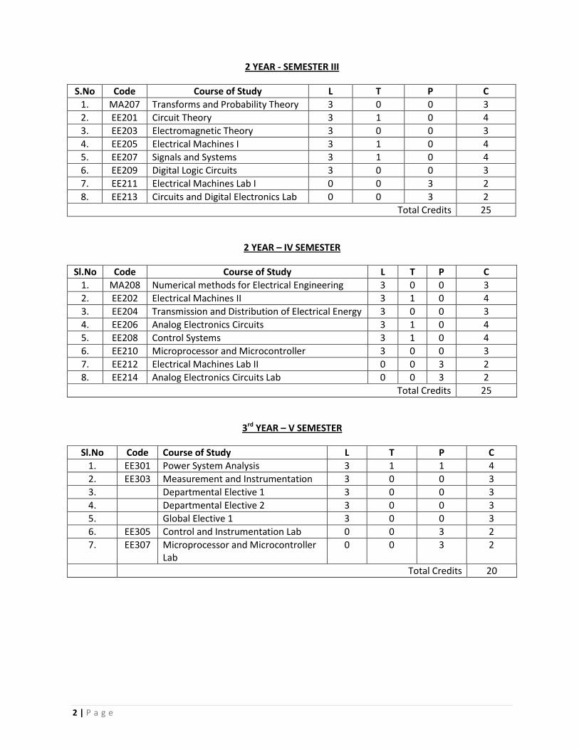
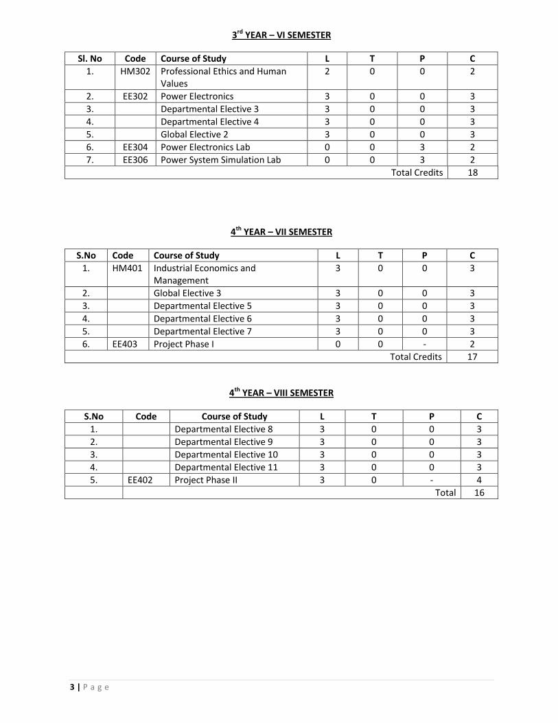
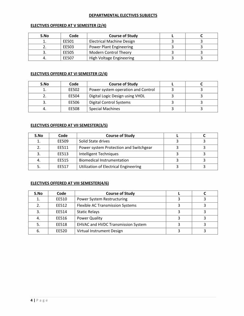
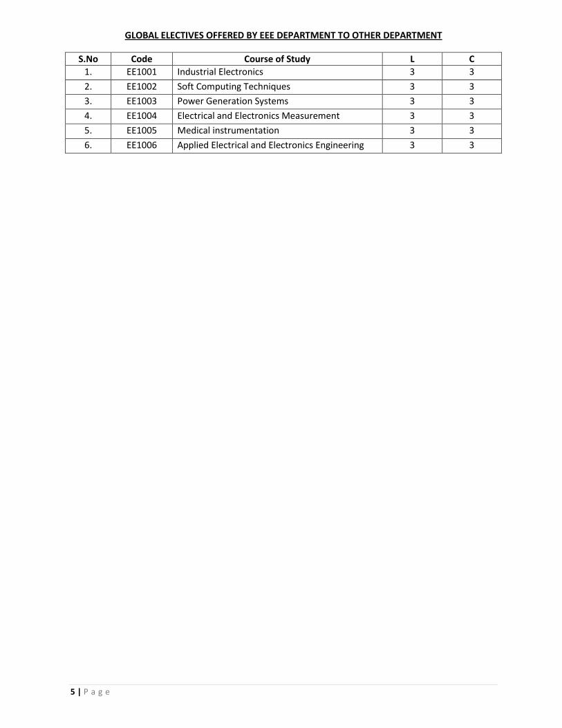


![CURRICULUM AND SYLLABI FOR B.TECH DEGREE … · [type text] curriculum and syllabi for b.tech degree programme in electrical and electronics engineering department of electrical engineering](https://static.documents.pub/doc/80x56/5b8845e57f8b9a2d238e9dd9/curriculum-and-syllabi-for-btech-degree-type-text-curriculum-and-syllabi.jpg)


