Copyright (c) 2010 IEEE. Personal use is permitted. For any other purposes, Permission must be obtained from the IEEE by emailing [email protected]. This article has been accepted for publication in a future issue of this journal, but has not been fully edited. Content may change prior to final publication. TBME-00737-2010 Abstract— The paper presents a study investigating the destructive energy output resulting from hydrodynamic bubbly cavitation in microchannels and its potential use in biomedical applications. The research performed in this study includes results from bubbly cavitation experiments and findings showing the destructive effects of bubbly cavitating flow on selected solid specimens and live cells. The bubbles generated by hydrodynamic cavitation are highly destructive at the surfaces of the target medium on which they are carefully focused. The resulting destructive energy output could be effectively used for biomedical treatment such as destroying kidney stones (renal calculi) or killing cancer cells. Motivated by this potential, the cavitation damage to cancerous cells and material removal from chalk pieces (which possess similar material properties as some kidney stones) was investigated. Our results showed that cavitation could induce damage both on chalk pieces and leukemia/lymphoma cells. We discovered that hydrodynamic cavitation exposure had early and delayed effects on cancer cell survival. Hence, the potential of hydrodynamic bubbly cavitation generated at the microscale for biomedical treatments was revealed using the microchannel configuration as a microorifice (with an inner diameter of 147 µm and a length of 1.52cm), which acts as the source of bubbly cavitating flows. Index Terms— Hydrodynamic cavitation, Bubbly cavitating flow, Microchannel, Cavitation damage, Cell death I. INTRODUCTION ydrodynamic cavitation is a progressive cycle of vaporization, bubble generation and bubble implosion. This cycle arises in a running liquid as a result of a decrease and consequent increase in local pressure. Hydrodynamic cavitation is initiated with local static pressure reduction below a critical pressure value, the saturated vapor pressure of the liquid in the case of no impurities in the liquid and the surface. Its effects on many types of turbomachinery have 1 been investigated by numerous researchers summarized in standard multiphase flow textbooks [1]-[3]. It is known that every hydraulic device is susceptible to the damage caused by cavitation once the appropriate cavitating flow conditions occur. In most cases, hydrodynamic cavitation is not desired 1 Manuscript received July 20, 2010. This work was supported by Sabancı University Internal Grant for Research Program under Grant IACF09-00642. Devrim Gözüaçık is a recipient of an “EMBO Installation Grant”. A. Koşar and D. Gozuacik (Equally contributing corresponding authors) are in the Mechatronics and Biological Sciences and Bioengineering Programs respectively, of the Faculty of Engineering and Natural Sciences, Sabancı University, Orhanlı, Tuzla, Istanbul, Turkey. Phones: 90- 216-483-9621 (A.K.) or -9617 (D.G.); fax: 90-216-483-9550; e-mails: [email protected] and [email protected]). since it limits the performance of a fluidic system, causes catastrophic damage and flow choking, generates acoustic noise, and lowers efficiency [1]. Due to its consequences and its destructive nature, cavitation and the energy associated with it constitute an important research subject, especially when these unwanted properties are used for therapeutic applications. There are two main sources for creating cavitating flow: hydrodynamic and ultrasonic sources. The use of ultrasonic cavitation in treatment of cancerous tissues has been investigated by various researchers [3]-[7]. As a result, ultrasonic sources have been the most popular means of generating cavitation in laboratory scale studies and, lately, it has been widely used in clinical practice. Therefore, numerous applications of ultrasonic cavitation (including biomedical applications) do exist [4]-[5]. Ultrasonic cavitation is a non-invasive treatment, where some difficulties are faced in targeting the precise location (kidney stone, abnormal tissue) of the treatment. To provide a better targeting, phased array probes are currently being employed [8]-[15]. A phased array probe consists of many small ultrasonic elements, each of which can be pulsed individually. By varying the timing, a pattern of constructive interference could be obtained so that a beam, which can be steered electronically, could be generated at a set angle. The resulting beam could be directed through the tissue or object being treated. Nevertheless, heat produced by ultrasound is responsible for some of the side effects produced by this treatment. These side effects include local pain, fistula formation, stress urinary incontinence and erectile dysfunction resulting from various degrees of nerve and tissue damage [16]. So, damage to tissue outside the target area is considered as a major drawback [17]. Moreover, the ultrasound treatment should not be applied over certain body parts such as eyes, female breasts and critical locations such as certain bone fractures and skin wounds [16]. To reduce the side effects, a newly developed ultrasound cavitation therapy method called “histotripsy” was introduced. Histotripsy uses bursts of ultrasound to destroy tissue by cavitation, so microbubbles rather than thermal mechanisms are responsible for its therapeutic effects [18]-[25]. In addition, ultrasonic cavitation applications have suffered from several shortcomings on industrial scale applications due to high frequency ultrasound usage. Research efforts to decrease the threshold of cavitation are present in the literature. The use of microdroplets of various contents [26], xanthene dyes [27], solid nanoparticles [28], bifrequency excitation [29]-[30], and the local introduction of shock wave- H Bubbly Cavitating Flow Generation and Investigation of its Erosional Nature for Biomedical Applications Ali Koşar, Muhsincan Şeşen, Ozlem Oral, Zeynep Itah, Devrim Gozuacik
Transcript
Copyright (c) 2010 IEEE. Personal use is permitted. For any other purposes, Permission must be obtained from the IEEE by emailing [email protected].
This article has been accepted for publication in a future issue of this journal, but has not been fully edited. Content may change prior to final publication.
TBME-00737-2010
Abstract— The paper presents a study investigating the destructive energy output resulting from hydrodynamic bubbly
cavitation in microchannels and its potential use in biomedical
applications. The research performed in this study includes
results from bubbly cavitation experiments and findings showing
the destructive effects of bubbly cavitating flow on selected solid
specimens and live cells.
The bubbles generated by hydrodynamic cavitation are highly
destructive at the surfaces of the target medium on which they
are carefully focused. The resulting destructive energy output
could be effectively used for biomedical treatment such as
destroying kidney stones (renal calculi) or killing cancer cells.
Motivated by this potential, the cavitation damage to cancerous
cells and material removal from chalk pieces (which possess
similar material properties as some kidney stones) was
investigated. Our results showed that cavitation could induce
damage both on chalk pieces and leukemia/lymphoma cells. We
discovered that hydrodynamic cavitation exposure had early and
delayed effects on cancer cell survival. Hence, the potential of
hydrodynamic bubbly cavitation generated at the microscale for
biomedical treatments was revealed using the microchannel
configuration as a microorifice (with an inner diameter of 147
µm and a length of 1.52cm), which acts as the source of bubbly
cavitating flows.
Index Terms— Hydrodynamic cavitation, Bubbly cavitating
flow, Microchannel, Cavitation damage, Cell death
I. INTRODUCTION
ydrodynamic cavitation is a progressive cycle of
vaporization, bubble generation and bubble implosion.
This cycle arises in a running liquid as a result of a decrease
and consequent increase in local pressure. Hydrodynamic
cavitation is initiated with local static pressure reduction
below a critical pressure value, the saturated vapor pressure of
the liquid in the case of no impurities in the liquid and the
surface. Its effects on many types of turbomachinery have 1been investigated by numerous researchers summarized in
standard multiphase flow textbooks [1]-[3]. It is known that
every hydraulic device is susceptible to the damage caused by
cavitation once the appropriate cavitating flow conditions
occur. In most cases, hydrodynamic cavitation is not desired
1 Manuscript received July 20, 2010. This work was supported by Sabancı University Internal
Grant for Research Program under Grant IACF09-00642. Devrim Gözüaçık is a recipient of an “EMBO
Installation Grant”.
A. Koşar and D. Gozuacik (Equally contributing corresponding authors) are in the
Mechatronics and Biological Sciences and Bioengineering Programs respectively, of the Faculty of
excitation [29]-[30], and the local introduction of shock wave-
H
Bubbly Cavitating Flow Generation and
Investigation of its Erosional Nature for
Biomedical Applications
Ali Koşar, Muhsincan Şeşen, Ozlem Oral, Zeynep Itah, Devrim Gozuacik
Copyright (c) 2010 IEEE. Personal use is permitted. For any other purposes, Permission must be obtained from the IEEE by emailing [email protected].
This article has been accepted for publication in a future issue of this journal, but has not been fully edited. Content may change prior to final publication.
TBME-00737-2010
generated bubbles [31] are some examples for reducing the
threshold of cavitation.
Another ultrasound based method called lithotripsy (shock
wave lithotripsy) is a non-invasive technique, which offers
important advantages for the treatment of renal and ureteral
stones [32]. It is the most common treatment for solitary,
uncomplicated, and small upper urinary tract calculi [33].
Success rate in shock wave lithotripsy can be increased by
providing treatment at a slow shock wave rate. However, some
stone types (e.g. brushite, calcium oxalate monohydrate, and
cysteine stones) could be resistant to this treatment [34]-[37].
Stone breakage with lithotripsy is not always complete and
patients are exposed to re-treatment or an additional clinical
procedure to remove residual fragments. Lithotripsy treatment
is limited to a maximum stone burden of around 2.5 cm since
renal anatomy could pose a barrier to the clearance of the
stone debris [38]. Reports describe unexpected and serious
adverse effects of lithotripsy [39]-[41]. For example, shock
wave treatment can rupture blood vessels, and can cause
severe acute renal injury.
Hydrodynamic cavitation is another candidate with a cost
effective and energy efficient solution [42]-[44] for
biomedical treatment. With the emergence of microfluidics,
hydrodynamic cavitation has been considered as an important
alternative to ultrasonic cavitation over the last decade.
Pioneering studies on hydrodynamic cavitation in
microchannels have been successful in showing the unique
properties of cavitating flow at the microscale [45]-[49].
Bubbles generated by hydrodynamic cavitation are highly
destructive on the applied surface, therefore; this technique
can be used efficiently as a minimally invasive surgical
technique to destroy urinary stones. With an appropriate
delivery system such as an endoscopic catheter, bubbles
produced by cavitating flow could be targeted to the desired
spot precisely so that the destructive nature of bubbly
cavitating flows could be used for abnormal tissue ablation
(e.g. benign prostate hyperplasia (BPH) or tumor ablation).
In the current study, the aim is to explore the feasibility of
this alternative treatment method. For this, destructive effects
of hydrodynamic cavitation are investigated and checked for
controllability and success in the above-mentioned targeting,
which would confirm its suitability for biomedical treatments.
II. MOTIVATION, EXPERIMENTAL APPARATUS AND PROCEDURE
A. Motivation and Theory
Reynolds was one of the first researchers who focused on
the subject of cavitation by trying to explain the unusual
behavior of ship propellers which were vulnerable to damage
because of their high rotational speeds. What Reynolds
achieved was to explain the phenomenon in terms of the
possible creation of air bubbles near the propeller blades. In
general we understand hydrodynamic cavitation as the
phenomenon of formation and growth of vapor or air pockets
in fluid flows as a result of local static pressure reduction
below a critical value. Cavitation bubbles collapse due to rapid
successive reduction and increase in local static pressure and
this leads to a high energy outcome, thereby generating highly
localized, large amplitude shock waves [1]-[2]. Such
cavitating flows could be initiated using a successful
microchannel and microorifice design. In contrast to
macroscale applications such as in propellers, this
configuration does not involve any moving parts. However, by
using the same concept of reducing the static pressure and
then releasing the emerging bubble to a higher pressure
medium, it is proposed to generate cavitation inside a
microorifice. As the fluid passes through the orifice throat, the
velocity of the fluid increases due to conservation of mass. As
a result, local static pressure of the fluid decreases in
consistency with the Bernoulli equation (with the assumption
of no frictional losses through the orifice and neglecting
frictional losses through the orifice):
If the pressure decreases to a certain critical value under
appropriate conditions, phase change takes place and bubbles
form inside the orifice. After the fluid passes through the
orifice throat, the pressure starts to increase again. Just after
the throat, there exists the exit area, where the bubbly
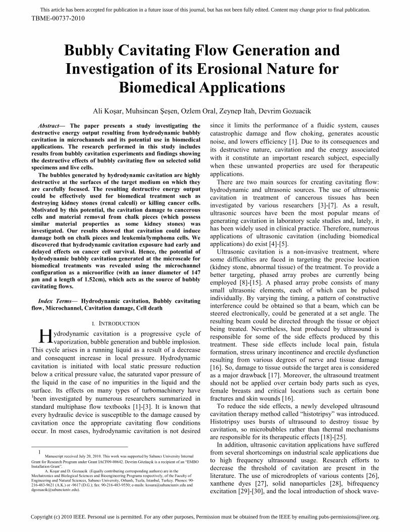
cavitation could be observed. In Fig. 1, the microchannel
configuration with the short orifice throat and exit area is
shown to provide insight into the cavitating system.
The bubble implosion caused by hydrodynamic bubbly
cavitation is highly destructive on targeted surfaces. Thus, if
they could be fine-controlled, they could be utilized for a
variety of treatments such as destroying kidney stones or
killing cancer cells.
The cavitation number, σ, is a dimensionless number used
for quantifying similar cavitating conditions and for
representing the intensity of cavitation. It can be quantified by
the difference between the local static pressure head and vapor
pressure head divided by the velocity head. It is defined as:
A reduction in cavitation number will increase the intensity
and the extent of the cavitation. The channel geometry also
affects the formation of cavitation. It is critical not to reduce
the cavitation number too much, since a transition from
Fig. 1. Microchannel configuration with the orifice throat and exit area.
Copyright (c) 2010 IEEE. Personal use is permitted. For any other purposes, Permission must be obtained from the IEEE by emailing [email protected].
This article has been accepted for publication in a future issue of this journal, but has not been fully edited. Content may change prior to final publication.
TBME-00737-2010
bubbly cavitation to supercavitation could occur. This would
be unsuitable for the purpose of the current study, which is to
generate continuous bubbly cavitating flow by designing a
microfluidic device (bubble generator), and then exposing the
emerging bubbles to a small target area (a piece of chalk as a
model of a kidney stone or a small area of sick tissue) and to
make observations on the changes in this area.
B. Experimental Setup and Procedure
Experimental set-up to create single-cavitation bubbles
A schematic of the experimental apparatus is shown in Figs.
2a and 2b. Sequential images of bubble growth and collapse
were captured by a Nikon SMZ 1500 stereoscopic zoom
microscope and Unibrain Fire-i 400 CCD camera unit. The
volumetric flow rates were measured with a flow meter.
Cavitation is generated by a microorifice, which is a plain
microchannel of inner diameter 147 µm, which is suitable for
both cavitation inception at moderate inlet pressures and
visualization, and is connected to the external tubing. The
tubing material is polyether ether ketone (PEEK), which is an
organic polymer thermoplastic used in various engineering
and medical applications such as medical implants. The
material involves a sheet of protection and has high resistance
to corrosion, thus it can be used in biomedical applications
that require sterile environments and equipment. The tubing
substrate is precisely laser drilled to the desired inner
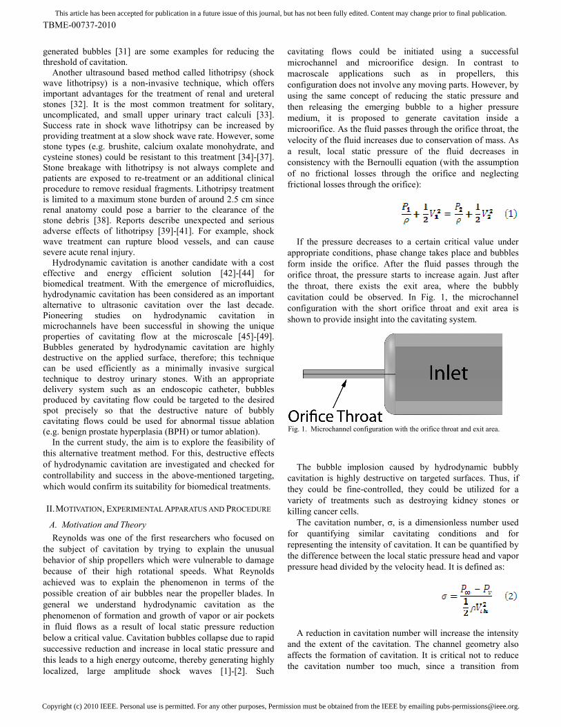
diameters for the experiments. A representative image of the
experiment is depicted in Fig. 3. The test setup consists of an
air compressor, a high pressure tank, a filter, a pressure gauge,
tubing, flow meter, and a fine control valve. The tank was
used as a container for deionized (DI) water, and the
compressor/Nitrogen tank was connected to the tank in order
to maintain input pressure. The filter was employed to prevent
the flow of any particle larger than 15 µm to the system.
Fig. 3. Picture of the experimental apparatus.
The tests were conducted by applying different inlet
pressure values. The maximum pressure applied at the inlet
was 10 atm, while the outlet pressure was set constant to 1 atm
during tests to better simulate the case for in vivo biomedical
applications. The flow rate was controlled with a fine-
metering valve. Various inlet pressure values were applied
during the tests in order to observe the result at increasing
pressure differences until bubbly cavitating flow pattern is
obtained. To be reproducible, each experiment was repeated
five times.
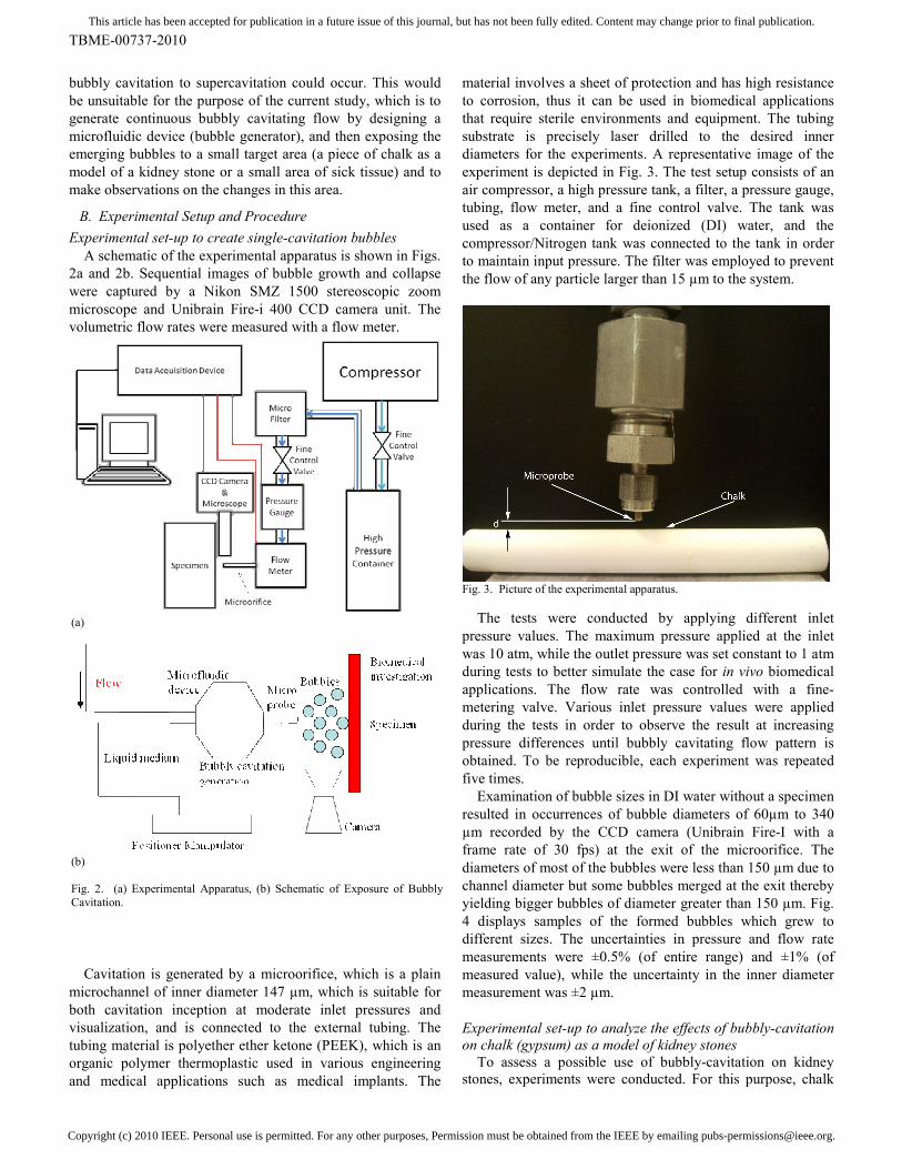
Examination of bubble sizes in DI water without a specimen
resulted in occurrences of bubble diameters of 60µm to 340
µm recorded by the CCD camera (Unibrain Fire-I with a
frame rate of 30 fps) at the exit of the microorifice. The
diameters of most of the bubbles were less than 150 µm due to
channel diameter but some bubbles merged at the exit thereby
yielding bigger bubbles of diameter greater than 150 µm. Fig.
4 displays samples of the formed bubbles which grew to
different sizes. The uncertainties in pressure and flow rate
measurements were ±0.5% (of entire range) and ±1% (of
measured value), while the uncertainty in the inner diameter
measurement was ±2 µm.
Experimental set-up to analyze the effects of bubbly-cavitation
on chalk (gypsum) as a model of kidney stones
To assess a possible use of bubbly-cavitation on kidney
stones, experiments were conducted. For this purpose, chalk
(a)
(b)
Fig. 2. (a) Experimental Apparatus, (b) Schematic of Exposure of Bubbly
Cavitation.
Copyright (c) 2010 IEEE. Personal use is permitted. For any other purposes, Permission must be obtained from the IEEE by emailing [email protected].
This article has been accepted for publication in a future issue of this journal, but has not been fully edited. Content may change prior to final publication.
TBME-00737-2010
(gypsum) was employed as a material with similar properties
to some kidney stones (Table 1). Natural urinary stones are
heterogeneous in size, shape, internal structure, mineral
composition, material properties and fragility to treatments
[50]. Since natural stones show significant variations with
respect to their properties (Table 1), they are rarely used
during optimizations aiming at determining the performance
of experimental treatments [51]. Instead, some investigators
have developed a variety of artificial models or phantom
stones to be utilized in renal calculi experiments [52]-[53].
Chalk and artifical stones provided important research tools
before applying the methods on natural urinary stones and
usage in the clinics (e.g. lithotripsy or ultrasonic cavitation).
Chalk (Gypsum, calcium sulfate dihydrate) has been widely
used in such investigations by several researchers [54]-[55].
The depth of penetration was measured after placing the
piece of chalk 1-2 mm downstream just in front of the outlet.
All consecutive test runs were made under the same working
conditions.
Table 1. Material properties of chalk (gypsum) and some common kidney
stones [52], [54], [56]
Properties
Chalk
(Gypsum)
[54], [56]
Kidney Stones [52]
Chemical
Composition
Calcium
sulfate
dihydrate
Calcium
oxalate
monohydrate
Brushite
(95%
calcium
phosphate,
5%
calcium
oxalate)
Uric
Acid
Amino
Acid
Cysteine
Magnesium
ammonium
phosphate
(90%)
Calcium
apatite
(10%)
Density
(g/cm3) 2.32 2.038 2.157 1.546 1.624 1.587
Young’s
Modulus
(GPa)
10.8 24.51 19.50 9.20 20.07 10.52
Shear
Modulus
(GPa)
7.47 9.20 7.20 3.30 7.33 4.24
Poisson’s
Ratio 0.34 0.33 0.36 0.39 0.37 0.24
Cancerous Cell Culture for Cavitation Experiments
The same experimental method and apparatus were used to
initiate bubbly cavitation for the experiments on cells. Jurkat,
acute T cell leukemia, and myelomonocytic U937 human
histiocytic lymphoma cell lines were chosen as cancer models
because they grow well in suspension and they are easy to
manipulate.
Jurkat and U937 were obtained from the American Type
Culture Collection (ATCC). These cells were cultured in
RPMI-1640 medium containing 10% Fetal Bovine Serum, 2
mM L-glutamine, 100µg penisillin/ 100U streptomycin, 55µM
β-mercaptoethanol at 37°C in a humid 5% CO2–95% air
environment. Medium was replaced every 2 to 3 days.
For the time-dependent treatments, the cells were cultured
in 75cm2 flasks and maintained at a cell concentration of 1x10
6
cells/ml. All equipments were sterilized with 70% ethanol and
then washed with a sterile physiological solution (phosphate
buffered saline, PBS). PBS was used as a liquid environment
to produce cavitation. Cells were exposed to bubbly cavitation
under an inlet pressure of about 950 kPa (inlet pressure was
increased until a cavitating flow pattern was obtained) for 0.5,
1, 2, 3 and 5 minutes, while the outlet pressure (pressure in the
solution) was kept at atmospheric pressure.
Cell Death Analysis
Jurkat and U-937 cells were exposed to hydrodynamically
produced bubbly cavitation and then centrifuged at 300xg for
5 minutes, washed and transferred to a fresh culture medium.
They were then evaluated for cell death (0 h) or incubated for
16 or 24 hours. As a cavitation control, PBS of a comparable
flow rate was applied on cells using a larger channel (3mm.
dia) that did not create cavitation. During the experiments,
control cells were treated the same way as their counterparts
exposed to cavitation.
Cells were harvested at the indicated time points and death
was concomitantly assessed using the trypan blue exclusion
technique. Estimation of viability by trypan blue exclusion
relies on the loss in membrane integrity (a late event in cell
death) that is determined by the uptake of a trypan blue dye to
which cells are normally impermeable.
III. RESULTS AND DISCUSSION
A. Results with Chalk Specimens for Kidney Stone
Simulation
During the experiments, in order to measure the penetration
effect of cavitation, pieces of chalk were used as specimens.
The depths were measured with a microscope after marking
the deepest point of the chalk piece without further damaging.
In Fig. 5a, the penetration depth is displayed as a function
of time. As expected, the penetration in the chalk medium
increases with time. It is also evident that the distance between
the microprobe and the specimen is an important parameter.
The penetration depth is larger for closer distances due to
stronger bubble-specimen surface interactions. The data for
penetration depth were converted to the mass removed by
Fig. 4. Sample images of the bubbles.
Copyright (c) 2010 IEEE. Personal use is permitted. For any other purposes, Permission must be obtained from the IEEE by emailing [email protected].
This article has been accepted for publication in a future issue of this journal, but has not been fully edited. Content may change prior to final publication.
TBME-00737-2010
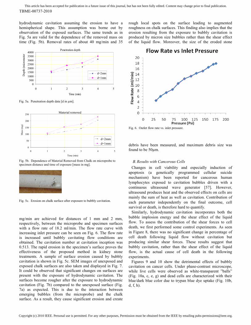
hydrodynamic cavitation assuming the erosion to have a
hemispherical shape. This assumption was borne out by
observation of the exposed surfaces. The same trends as in
Fig. 5a are valid for the dependence of the removed mass on
time (Fig. 5b). Removal rates of about 40 mg/min and 35
mg/min are achieved for distances of 1 mm and 2 mm,
respectively, between the microprobe and specimen surfaces
with a flow rate of 18.2 ml/min. The flow rate curve with
increasing inlet pressure can be seen on Fig. 6. The flow rate
is increased until bubbly cavitating flow conditions are
obtained. The cavitation number at cavitation inception was
0.513. The rapid erosion in the specimen’s surface proves the
effectiveness of the proposed method in kidney stone
treatments. A sample of surface erosion caused by bubbly
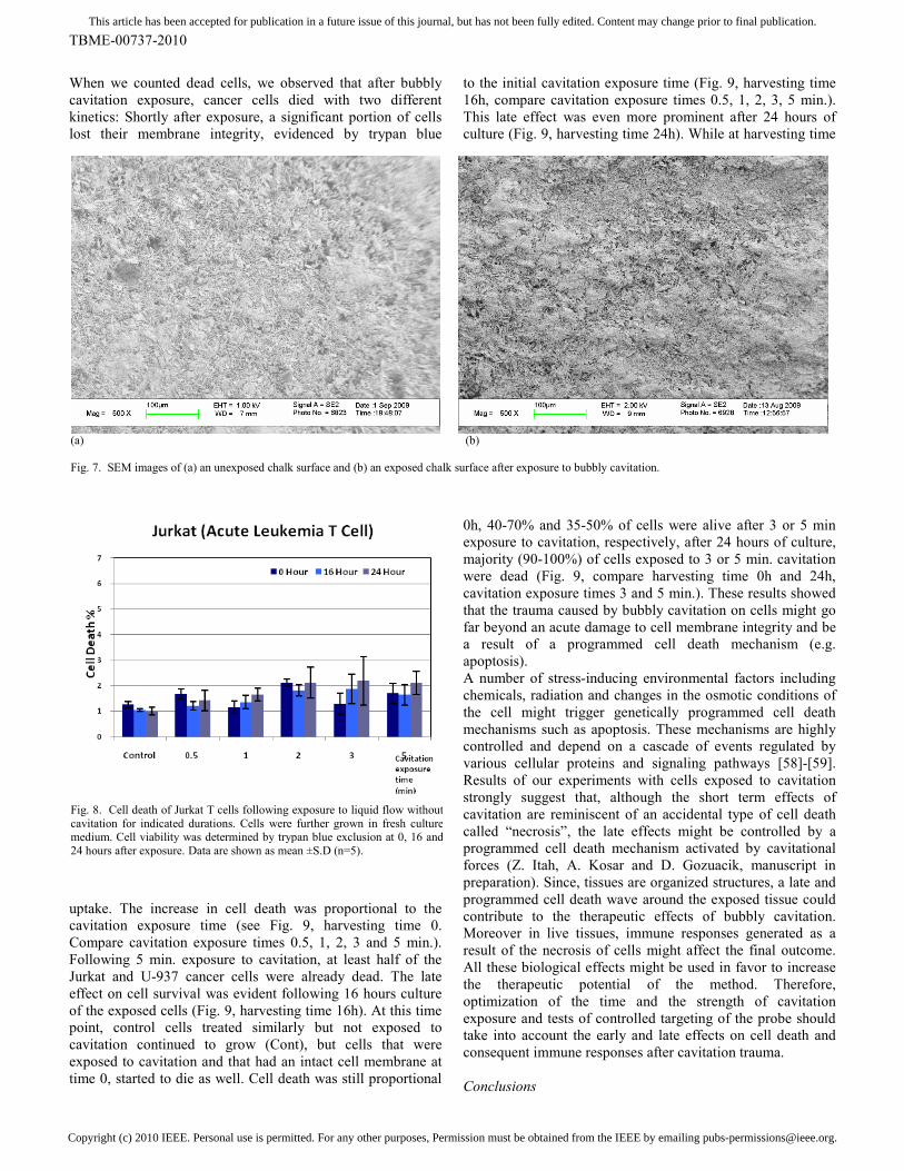
cavitation is shown in Fig. 5c. SEM images of unexposed and
exposed chalk surfaces are also taken and displayed in Fig. 7.
It could be observed that significant changes on surfaces are
present with the exposure of hydrodynamic cavitation. The
surfaces become rougher after the exposure to hydrodynamic
cavitation (Fig. 7b) compared to the unexposed surface (Fig.
7a) as expected. This is due to the interaction between
emerging bubbles (from the microprobe) and the chalk
surface. As a result, they cause significant erosion and create
rough local spots on the surface leading to augmented
roughness on chalk surfaces. This finding also implies that the
erosion resulting from the exposure to bubbly cavitation is
produced by micron size bubbles rather than the shear effect
of the liquid flow. Moreover, the size of the eroded stone
debris have been measured, and maximum debris size was
found to be 50µm.
B. Results with Cancerous Cells
Changes in cell viability and especially induction of
apoptosis (a genetically programmed cellular suicide
mechanism) have been reported for cancerous human
lymphocytes exposed to cavitation bubbles driven with a
continuous ultrasound wave generator [57]. However,
ultrasound produces heat and the observed effects on cells are
mainly the sum of heat as well as cavitation. Contribution of
each parameter independently on the final outcome, cell
survival or death, is therefore hard to quantify.
Similarly, hydrodynamic cavitation incorporates both the
bubble implosion energy and the shear effect of the liquid
flow. To assess the contribution of the shear forces to cell
death, we first performed some control experiments. As seen
in Figure 8, there was no significant change in percentage of
cell death following liquid flow without cavitation but
producing similar shear forces. These results suggest that
bubbly cavitation, rather than the shear effect of the liquid
flow, is the actual cause of cell death in the following
experiments.
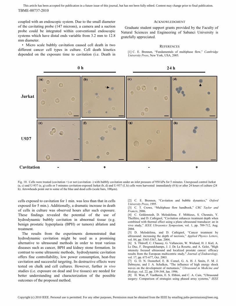
Figures 9 and 10 show the detrimental effects of bubbly
cavitation on cancer cells. Under phase-contrast microscope,
while live cells were observed as white-transparent ”balls”
(Fig. 10a, c, e, g) and dead cells are characterized with their
blue/dark blue color due to trypan blue dye uptake (Fig. 10b,
d, f, h).
Penetration depth
0
500
1000
1500
2000
2500
3000
3500
4000
0 1 2 3 4 5
Time (min)
Depth (micrometer)
d=2mm
d=1mm
Fig. 5a. Penetration depth data [d in µm].
Material removed
0
50
100
150
200
250
0 1 2 3 4 5
Time (min)
Mass (m
g)
d=2mm
d=1mm
Fig. 5b. Dependence of Material Removed from Chalk on microprobe to
specimen distance and time of exposure [mass in mg].
Fig. 5c. Erosion on chalk surface after exposure to bubbly cavitation.
Fig. 6. Outlet flow rate vs. inlet pressure.
Copyright (c) 2010 IEEE. Personal use is permitted. For any other purposes, Permission must be obtained from the IEEE by emailing [email protected].
This article has been accepted for publication in a future issue of this journal, but has not been fully edited. Content may change prior to final publication.
TBME-00737-2010
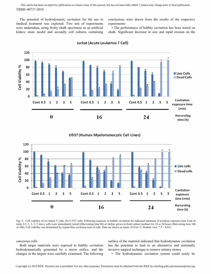
When we counted dead cells, we observed that after bubbly
cavitation exposure, cancer cells died with two different
kinetics: Shortly after exposure, a significant portion of cells
lost their membrane integrity, evidenced by trypan blue
uptake. The increase in cell death was proportional to the
cavitation exposure time (see Fig. 9, harvesting time 0.
Compare cavitation exposure times 0.5, 1, 2, 3 and 5 min.).
Following 5 min. exposure to cavitation, at least half of the
Jurkat and U-937 cancer cells were already dead. The late
effect on cell survival was evident following 16 hours culture
of the exposed cells (Fig. 9, harvesting time 16h). At this time
point, control cells treated similarly but not exposed to
cavitation continued to grow (Cont), but cells that were
exposed to cavitation and that had an intact cell membrane at
time 0, started to die as well. Cell death was still proportional
to the initial cavitation exposure time (Fig. 9, harvesting time
This late effect was even more prominent after 24 hours of
culture (Fig. 9, harvesting time 24h). While at harvesting time
0h, 40-70% and 35-50% of cells were alive after 3 or 5 min
exposure to cavitation, respectively, after 24 hours of culture,
majority (90-100%) of cells exposed to 3 or 5 min. cavitation
were dead (Fig. 9, compare harvesting time 0h and 24h,
cavitation exposure times 3 and 5 min.). These results showed
that the trauma caused by bubbly cavitation on cells might go
far beyond an acute damage to cell membrane integrity and be
a result of a programmed cell death mechanism (e.g.
apoptosis).
A number of stress-inducing environmental factors including
chemicals, radiation and changes in the osmotic conditions of
the cell might trigger genetically programmed cell death
mechanisms such as apoptosis. These mechanisms are highly
controlled and depend on a cascade of events regulated by
various cellular proteins and signaling pathways [58]-[59].
Results of our experiments with cells exposed to cavitation
strongly suggest that, although the short term effects of
cavitation are reminiscent of an accidental type of cell death
called “necrosis”, the late effects might be controlled by a
programmed cell death mechanism activated by cavitational
forces (Z. Itah, A. Kosar and D. Gozuacik, manuscript in
preparation). Since, tissues are organized structures, a late and
programmed cell death wave around the exposed tissue could
contribute to the therapeutic effects of bubbly cavitation.
Moreover in live tissues, immune responses generated as a
result of the necrosis of cells might affect the final outcome.
All these biological effects might be used in favor to increase
the therapeutic potential of the method. Therefore,
optimization of the time and the strength of cavitation
exposure and tests of controlled targeting of the probe should
take into account the early and late effects on cell death and
consequent immune responses after cavitation trauma.
Conclusions
(a) (b)
Fig. 7. SEM images of (a) an unexposed chalk surface and (b) an exposed chalk surface after exposure to bubbly cavitation.
Fig. 8. Cell death of Jurkat T cells following exposure to liquid flow without
cavitation for indicated durations. Cells were further grown in fresh culture medium. Cell viability was determined by trypan blue exclusion at 0, 16 and
24 hours after exposure. Data are shown as mean ±S.D (n=5).
Copyright (c) 2010 IEEE. Personal use is permitted. For any other purposes, Permission must be obtained from the IEEE by emailing [email protected].
This article has been accepted for publication in a future issue of this journal, but has not been fully edited. Content may change prior to final publication.
TBME-00737-2010
The potential of hydrodynamic cavitation for the use in
medical treatment was explored. Two sets of experiments
were undertaken, using firstly chalk specimens as an artificial
kidney stone model and secondly cell cultures containing
cancerous cells.
Both target materials were exposed to bubbly cavitation
hydrodynamically generated by a micro orifice, and the
changes in the targets were carefully examined. The following
conclusions were drawn from the results of the respective
experiments:
• The performance of bubbly cavitation has been tested on
chalk. Significant decrease in size and rapid erosion on the
surface of the material indicated that hydrodynamic cavitation
has the potential to lead to an alternative and minimally
invasive surgical technique to remove urinary stones.
• The hydrodynamic cavitation system could easily be
Fig. 9. Cell viability of (a) Jurkat T cells, (b) U-937 cells. Following exposure to bubbly cavitation for indicated durations (Cavitation exposure time Cont (0
min), 0.5, 1, 2, 3, 5 min.), cells were immediately tested ((Harvesting time 0h) or further grown in fresh culture medium for 16 or 24 hours (Harvesting time 16h or 24h). Cell viability was determined by trypan blue exclusion tests of cells. Data are shown as mean ±S.D (n=5, Student t test, * P < 0,01).
Copyright (c) 2010 IEEE. Personal use is permitted. For any other purposes, Permission must be obtained from the IEEE by emailing [email protected].
This article has been accepted for publication in a future issue of this journal, but has not been fully edited. Content may change prior to final publication.
TBME-00737-2010
coupled with an endoscopic system. Due to the small diameter
of the cavitating probe (147 microns), a camera and a suction
probe could be integrated within conventional endoscopic
systems which have distal ends variable from 3.2 mm to 12.8
mm diameter.
• Micro scale bubbly cavitation caused cell death in two
different cancer cell types in culture. Cell death kinetics
depended on the exposure time to cavitation (i.e. Death in
cells exposed to cavitation for 1 min. was less than that in cells
exposed for 5 min.). Additionally, a dramatic increase in death
of cells in culture was observed hours after such exposure.
These findings revealed the potential of the use of
hydrodynamic bubbly cavitation in abnormal tissue (e.g.
benign prostatic hyperplasia (BPH) or tumors) ablation and
treatment.
The results from the experiments demonstrated that
hydrodynamic cavitation might be used as a promising
alternative to ultrasound methods in order to treat various
diseases such as cancer, BPH and kidney stone formation. In
contrast to some ultrasonic methods, hydrodynamic cavitation
offers fine controllability, low power consumption, heat-free
cavitation and successful targeting. Its destructive effects were
tested on chalk and cell cultures. However, further in vivo
studies (i.e. exposure on dead and live tissues) are needed for
better understanding and characterization of the possible
outcomes of the proposed method.
ACKNOWLEDGMENT
Graduate student support grants provided by the Faculty of
Natural Sciences and Engineering of Sabanci University is
gratefully appreciated.
REFERENCES
[1] C. E. Brennen, “Fundamentals of multiphase flow,” Cambridge
University Press, New York, USA, 2005.
[2] C. E. Brennen, “Cavitation and bubble dynamics,” Oxford
University Press, 1995.
[3] C. T. Crowe, “Multiphase flow handbook,” CRC Taylor and Francis, 2006.
[4] C. Goldenstedt, D. Melodelima. F. Mithieux, S. Chesnais, Y.
Theillère, and D. Cathignol, “Cavitation enhances treatment depth when combined with thermal effect using a plane ultrasound transducer: an in
vivo study,” IEEE Ultrasonics Symposium, vol. 1, pp. 709-712, Aug.
2004. [5] D. Melodelima, and D. Cathignol, “Cancer treatment by
ultrasound: increasing the depth of necrosis,” Applied Physics Letters,
vol. 84, pp. 5365-5367, Jun. 2004. [6] S. Thüroff, C. Chaussy, G. Vallancien, W. Wieland, H. J. Kiel, A.
Le Duc, F. Desgrandchamps, J. J. De La Rosette, and A. Gelet, "High
intensity focused ultrasound and localized prostate cancer: efficacy results from the European multicentric study," Journal of Endourology,
vol. 17, pp. 673-677, Oct. 2003.
[7] G. O. N. Oosterhof, E. B. Comel, G. A. H. J. Smits, F. M. J. Debruyne, and J. A. Schalken, “The influence of high energy shock
waves on the development of metastasis,” Ultrasound in Medicine and
Biology, vol. 22, pp. 339-344, Jan. 1996. [8] H. Wan, P. VanBaren, E. S. Ebbini, and C. A. Cain, “Ultrasound
surgery: Comparison of strategies using phased array systerns,” IEEE
Fig. 10. Cells were treated (cavitation +) or not (cavitation -) with bubbly cavitation under an inlet pressure of 950 kPa for 5 minutes. Unexposed control Jurkat
(a, c) and U-937 (e, g) cells or 5 minutes cavitation-exposed Jurkat (b, d) and U-937 (f, h) cells were harvested immediately (0 h) or after 24 hours of culture (24 h). Arrowheads point out to some of the blue and dead cells (scale bars, 100µm).
Copyright (c) 2010 IEEE. Personal use is permitted. For any other purposes, Permission must be obtained from the IEEE by emailing [email protected].
This article has been accepted for publication in a future issue of this journal, but has not been fully edited. Content may change prior to final publication.
TBME-00737-2010
Transactions on Ultrasonics, Ferroelectrics, and Frequency Control,
vol. 43, pp. 1085-1098, Nov. 1996. [9] L. R. Gavrilov, and J. W. Hand, “Development and investigation of
ultrasound linear phased arrays for transrectal treatment of prostate,”
Ultrasonics Sonochemistry, vol. 4, pp. 173-174, Apr. 1997. [10] J. Tavakkoli, A. Mehta, C. Miller, R. Seip, N. T. Sanghvi1, L.
Cheng, T. A. Gardner, and A. L. Shalhav, “A laparoscopic HIFU probe
with integrated phased array ultrasound imaging,” Third International Symposium on Therapeutic Ultrasound, Jun. 2003.
[11] K. Hynynen, G. T. Clement, N. McDannold, N. Vykhodtseva, R.
King, P. J. White, S. Vitek, and F. A. Jolesz, “500-Element ultrasound phased array system for noninvasive focal surgery of the brain: A
preliminary rabbit study with ex vivo human skulls,” Magnetic
Resonance in Medicine, vol. 52, pp. 100-107, Jun. 2004. [12] K. Y. Saleh, and N. B. Smith, “Two-dimensional ultrasound
phased array design for tissue ablation for treatment of benign prostatic
hyperplasia,” International Journal of Hyperthermia, vol. 20, pp. 7-31, Feb. 2004.
[13] K. Y. Saleh, and N. B. Smith, “A 63 element 1.75 dimensional
ultrasound phased array for the treatment of benign prostatic hyperplasia,” Biomedical Engineering Online, vol. 4, Jun. 2005.
[14] D. Melodelima, R. Salomir, C. Mougenot, C. Moonen, and D.
Cathignol, “64-Elements intraluminal ultrasound cylindrical phased array for transesophageal thermal ablation under fast MR temperature
mapping: An ex vivo study,” Medical Physics, vol. 33, pp. 2926-2934,
Aug. 2006. [15] J. F. Bakker, M. M. Paulides, I. M. Obdeijn, G. C. van Rhoon, and
K. W. A. van Dongen, “An ultrasound cylindrical phased array for deep heating in the breast: theoretical design using heterogeneous models,”
Physics in Medicine and Biology, vol. 54, pp. 3201–3215, May 2009.
[16] C. R. Merritt, “Ultrasound safety: what are the issues?,” Radiology, vol. 173, pp. 304-306, Nov. 1989.
[17] E. J. Halpern, “High-intensity focused ultrasound ablation: Will
image-guided therapy replace conventional surgery?,” Science to Practice, vol. 235, pp. 345-346, May 2005.
[18] Z. Xu, A. Ludomirsky, L. Y. Eun, T. L. Hall, B. C. Tran, J. B.
Fowlkes, and C. A. Cain, “Controlled ultrasound tissue erosion,” IEEE Transactions on Ultrasonics, Ferroelectrics, and Frequency Control,
vol. 51, pp. 726-736, Jun. 2004.
[19] J. E. Parsons, C. A. Cain, G. D. Abrams, and J. B. Fowlkes, “Pulsed cavitational ultrasound therapy for controlled tissue
homogenization,” Ultrasound in Medicine & Biology, vol. 32, pp. 115-
129, Jan. 2006. [20] W. W. Roberts, T. J. Hall, K. Ives, J. J. S. Wolf, J. B. Fowlkes, and
C. A. Cain, “Pulsed cavitational ultrasound : a noninvasive technology
for controlled tissue ablation (histotripsy) in the rabbit kidney,” Journal of Urology, vol. 175, pp. 734-738, Feb. 2006.
[21] A. M. Lake, T. L. Hall, K. Kieran, J. B. Fowlkes, C. A. Cain, and
W. W. Roberts, “Histotripsy: minimally invasive technology for prostatic tissue ablation in an in vivo canine model,” Urology, vol. 72,
pp. 682-686, Sep. 2008.
[22] K. Kieran, T. L. Hall, J. E. Parsons, J. S. Wolf, J. B. Fowlkes, C. A. Cain, and W. W. Roberts, “Refining histotripsy: defining the parameter
space for the creation of nonthermal lesions with high intensity, pulsed
focused ultrasound of the in vitro kidney,” Journal of Urology, vol. 178, pp. 672-676, Aug. 2007.
[23] Z. Xu, M. Raghavan, T. L. Hall, M. A. Mycek, J. B. Fowlkes, and
C. A. Cain, “Evolution of bubble clouds produced in pulsed cavitational ultrasound therapy – histotripsy,” IEEE Transactions on Ultrasonics,
Ferroelectrics, and Frequency Control, vol. 55, pp. 1122-1132, May
2008. [24] T. Y. Wang, Z. Xu, F. Winterroth, T. L. Hall, E. D. Rothman, J. B.
Fowlkes, W. W. Roberts, and C. A. Cain, “Quantitative ultrasound
backscatter for pulsed cavitational ultrasound therapy- Histotripsy,” IEEE Transactions on Ultrasonics, Ferroelectrics, and Frequency
Control, vol. 56, pp. 995-1005, May 2009.
[25] Z. Xu, G. Owens, D. Gordon, C. A. Cain, and A. Ludomirsky, “Non-invasive creation of an atrial septal defect by histotripsy in a
canine codel,” Circulation, vol. 121, pp. 742-749, Feb. 2010.
[26] T. Giesecke, and K. Hynynen, “Ultrasound-mediated cavitation thresholds of liquid perfluorocarbon droplets in vitro,” Ultrasound in
Medicine & Biology, vol. 29, pp. 1359-1365, Sep. 2003.
[27] K. Kawabata, and S. Umemura, “Xanthene dyes for reducing acoustic cavitation threshold in aqueous solution,” Ultrasonics, vol. 35,
pp. 469-474, Sep. 1997.
[28] V. Larina, B. M. Evers, T. V. Ashitkov, C. Bartels, K. V. Larin, and
R. O. Esenaliev, “Enhancement of drug delivery in tumors by using interaction of nanoparticles with ultrasound radiation,” Technology in
Cancer Research & Treatment, vol. 4, pp. 217-226, Apr. 2005.
[29] B. Gilles, J. C. Béra, J. L. Mestas, and D. Cathignol, “Reduction of ultrasound inertial cavitation threshold using bifrequency excitation,”
Applied Physics Letters, vol. 89, Aug. 2006.
[30] I. Saletes, B. Gilles, and J. C. Bera, “Promoting inertial cavitation by nonlinear frequency mixing in a bifrequency focused ultrasound
beam,” Ultrasonics, vol. 51, pp. 94-101, Jan. 2011.
[31] W. S. Chen, T. J. Matula, A. A. Brayman, and L. A. Crum, “A comparison of the fragmentation thresholds and inertial cavitation doses
of different ultrasound contrast agents,” The Journal of the Acoustical
Society of America, vol. 113, pp. 643-651, Jan. 2003. [32] J. E. Lingeman, J. Woods, P. D. Toth, A. P. Evan, and J. A.
McAteer, “The role of lithotripsy and its side effects,” Journal of
Urology, vol. 141, pp. 793-797, Mar. 1989. [33] J. E. Lingeman, J. A. McAteer, E. Gnessin, and A. P. Evan, “Shock
wave lithotripsy: advances in technology and technique,” Nature
Reviews Urology, vol. 6, pp. 660-670, Dec. 2009 [34] S. P. Dretler, “Stone fragility—a new therapeutic distinction,”
Journal of Urology, vol. 139, pp. 1124-1127, May 1988
[35] L. W. Klee, C. G. Brito, and J. E. Lingeman, “The clinical implications of brushite calculi,” Journal of Urology, vol. 145, pp. 715-
718, Apr. 1991
[36] P. Zhong, C. J. Chuong, and G. M. Preminger, “Characterization of fracture toughness of renal calculi using microindentation technique,”
Journal of Materials Science Letters, vol. 12, pp. 1460-1462, Jan. 1993. [37] S. C. Kim, E. K. Burns, J. E. Lingeman, R. F. Paterson, J. A.
McAteer, and J. C. Williams Jr., “Cystine calculi: correlation of CT-
visible structure, CT number, and stone morphology with fragmentation by shock wave lithotripsy,” Urological Research, vol. 35, pp. 319-324,
Dec. 2007.
[38] J. E. Lingeman, B. R. Matlaga, and A. P. Evan, “Surgical management of upper urinary tract calculi,” Campbell–Walsh Urology,
9th ed. Philadelphia, Saunders (an imprint of Elsevier Science), Chapter
9, Chapter 44, pp. 1431-1507, 2006. [39] J. V. Kaude, C. M. Williams, M. R. Millner, K. N. Scott, and B.
Finlayson, “Renal morphology and function immediately after
extracorporeal shock-wave lithotripsy,” American Journal of Roentgenology, vol. 145, pp. 305- 313, Aug. 1985.
[40] A .P. Evan, and J. A. McAteer, “Kidney Stones: Medical and
[41] J. A. McAteer, and A. P. Evan, “The acute and long-term adverse
effects of shock wave lithotripsy,” Seminars in Nephrology, vol. 28, pp. 200-213, Mar. 2008.
[42] V. S. Moholkar, and A. B. Pandit, “Modeling of hydrodynamic
cavitation reactors: a unified approach,” Chemical Engineering Science, vol. 56, pp. 6295-6302, Nov. 2001.
[43] V. S. Moholkar, and A. B. Pandit, “Numerical investigations in the
behavior of one-dimensional bubbly flow in hydrodynamic cavitation,” Chemical Engineering Science, vol. 56, pp. 1411-1418, Feb. 2001.
[44] S. Arrojo, and Y. Benito, “A theoretical study of hydrodynamic
cavitation,” Ultrasonics Sonochemistry, vol. 15, pp. 203-211, Mar. 2008. [45] C. Mishra, and Y. Peles, “Flow visualization of cavitating flows
through a rectangular slot micro-orifice ingrained in a microchannel,”
Physics of Fluids, vol. 17, pp. 113602-113615, Nov. 2005. [46] C. Mishra, and Y. Peles, “Size scale effects on cavitating flows
through microorifices entrenched in rectangular microchannels,” Journal
of Microelectromechanical Systems, vol. 14, pp. 987-999, 2005. [47] C. Mishra, and Y. Peles, “An experimental investigation of
hydrodynamic cavitation in micro-venturis,” Physics of Fluids, vol. 18,
pp. 103603-103607, Oct. 2006. [48] C. Mishra, and Y. Peles, “Cavitation in flow through a micro-orifice
inside a silicon microchannel,” Physics of Fluids, vol. 17, pp.013601-
013615, Jan. 2005. [49] B. Schneider, A. Kosar, C. J. Kuo, C. Mishra, G. S. Cole, R. P.
Scaringe, and Y. Peles, “Cavitation enhanced heat transfer in
microchannels,” Journal of Heat Transfer, vol. 128, pp. 1293-1301, Dec. 2006.
[50] J. C. Williams Jr., K. C. Saw, R. F. Paterson, E. K. Hatt, J. A.
McAteer, and J. E. Lingeman, “Variability of renal stone fragility in shock wave lithotripsy,” Urology, vol. 61, pp. 1092-1096, Jun. 2003.
Copyright (c) 2010 IEEE. Personal use is permitted. For any other purposes, Permission must be obtained from the IEEE by emailing [email protected].
This article has been accepted for publication in a future issue of this journal, but has not been fully edited. Content may change prior to final publication.
TBME-00737-2010
[51] J. M. Teichman, A. J. Portis, P. P. Cecconi, W. L. Bub, R. C.
Endicott, B. Denes, M. S. Pearle, and R. V. Clayman, “In vitro comparison of shock wave lithotripsy machines,” Journal of Urology,
vol. 164, pp. 1259-1264, Oct. 2000.
[52] D. Heimbach, R. Munver, P. Zhong, A. Jacobs, A. Hesse, S. C. Muller, and G. M. Preminger, “Acoustic and mechanical properties of
artificial stones in comparison to natural kidney stones,” Journal of
Urology, vol. 164, pp. 537-544, Aug. 2000. [53] R. Bachmann, D. Heimbach, W. Kersjes, D. Jacobs, H. Schild, and
A. Hesse, “A new type of artificial urinary calculi: in vitro study by
spiral CT,” Investigative Radiology, vol. 35, pp. 672-675, Nov. 2000. [54] A. Mota, J. Knap, and M. Ortiz, “Three-dimensional fracture and
fragmentation of artificial kidney stones,” Journal of Physics:
Conference Series, vol. 46, pp. 299-303, Jul. 2006. [55] J. A. McAteer, J. C. Williams Jr., R. O. Cleveland, J. V.
Cauwelaert, M. R. Bailey, D. A. Lifshitz, and A. P. Evan, “Ultracal-30
gypsum artificial stones for research on the mechanisms of stone breakage in shock wave lithotripsy,” Journal of Urological Research,
vol. 33, pp. 429-434, Dec. 2005.
[56] Y. Fujii, and A.M. Nakamura , “Compaction and fragmentation of porous gypsum targets from low-velocity impacts,” Icarus, vol. 201, pp.
795-801, June 2009.
[57] L. B. Feril Jr., T. Kondo, Z. Cui, Y. Tabuchi, Q. Zhao, H. Ando, T. Misaki, H. Yoshikawa, and S. Umemura, “Apoptosis induced by the
sonomechanical effects of low intensity pulsed ultrasound in a human
leukemia cell line,” Cancer Letters, vol. 221, pp. 145-152, Apr. 2005. [58] D. Gozuacik, and A. Kimchi, “Autophagy and cell death,” Current
Topics in Developmental Biology, vol. 78, pp. 217-245, Mar. 2007. [59] D. Gozuacik, S. Bialik, T. Raveh, G. Mitou, G. Shohat, H. Sabanay,
N. Mizushima, T. Yoshimori, and A. Kimchi, “DAP-kinase is a
mediator of endoplasmic reticulum stress-induced caspase activation and autophagic cell death,” Cell Death and Differentiation, vol. 15, pp.


![Discrete Bubble Modeling of Unsteady Cavitating Flolu/resume/diesel.pdf · DISCRETE BUBBLE MODELING OF UNSTEADY CAVITATING FLOW 603 tion of state for multiphase (bubbly) flows [7].](https://static.documents.pub/doc/80x56/5e890a8d70378d177f50c7d7/discrete-bubble-modeling-of-unsteady-cavitating-luresumedieselpdf-discrete.jpg)


