Buckling of Rigid Frames – II Prof. Tzuyang Yu Structural Engineering Research Group (SERG) Department of Civil and Environmental Engineering University of Massachusetts Lowell Lowell, Massachusetts CIVE.5120 Structural Stability (3-0-3) 03/07/17
Transcript
Buckling of Rigid Frames – II
Prof. Tzuyang Yu Structural Engineering Research Group (SERG)
Department of Civil and Environmental Engineering University of Massachusetts Lowell
Lowell, Massachusetts
CIVE.5120 Structural Stability (3-0-3) 03/07/17
2
Outline
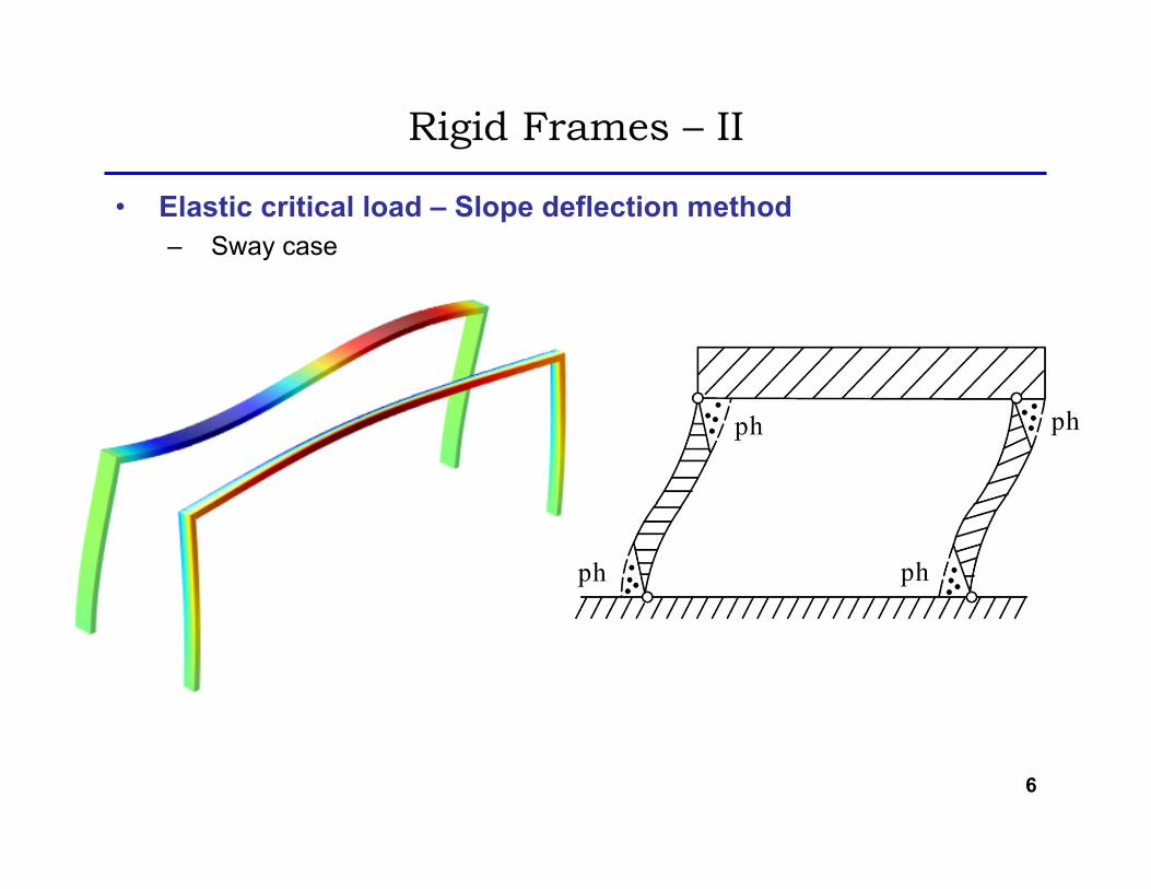
• Elastic critical loads – Slope deflection method – Non-sway case – Sway case
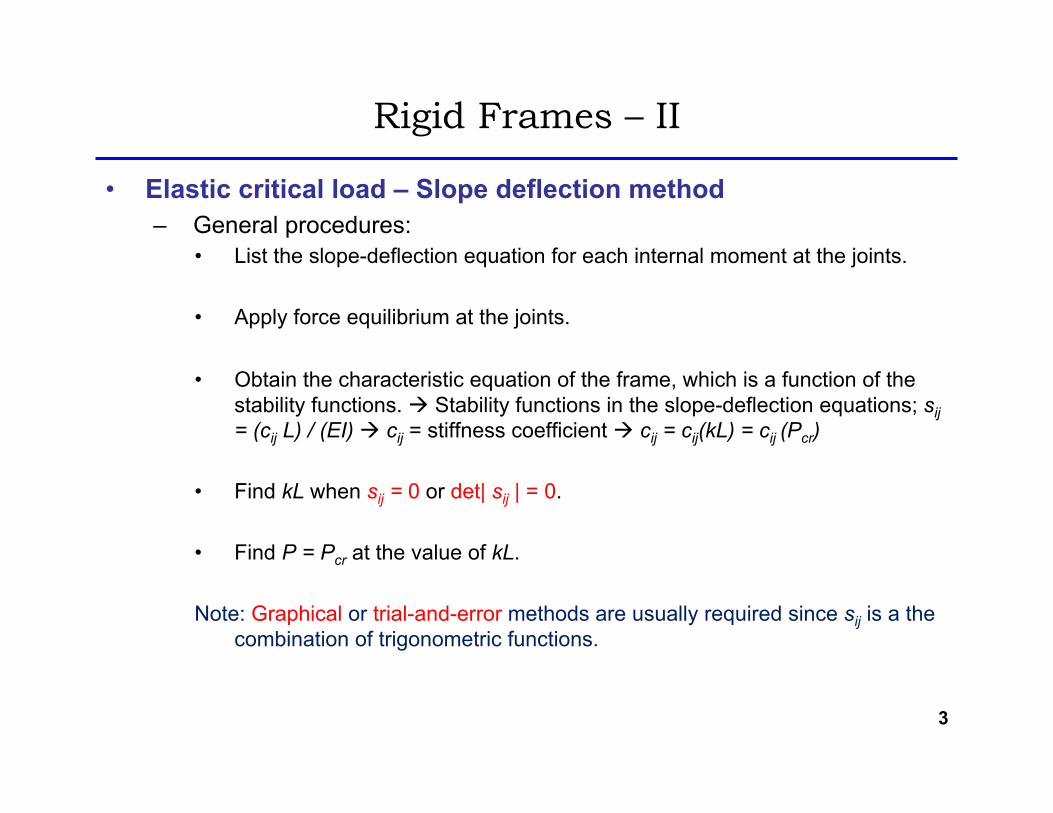
• List the slope-deflection equation for each internal moment at the joints.
• Apply force equilibrium at the joints.
• Obtain the characteristic equation of the frame, which is a function of the stability functions. à Stability functions in the slope-deflection equations; sij = (cij L) / (EI) à cij = stiffness coefficient à cij = cij(kL) = cij (Pcr)
• Find kL when sij = 0 or det| sij | = 0.
• Find P = Pcr at the value of kL.
Note: Graphical or trial-and-error methods are usually required since sij is a the combination of trigonometric functions.
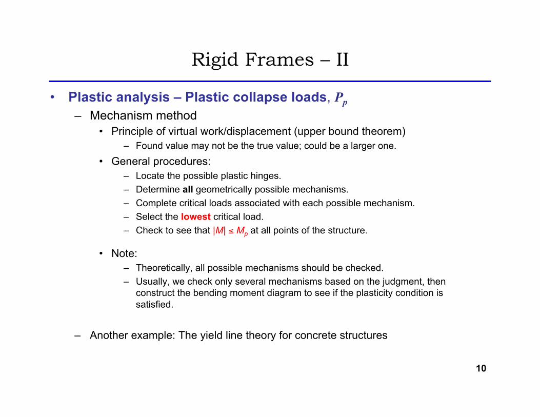
• Principle of virtual work/displacement (upper bound theorem) – Found value may not be the true value; could be a larger one.
• General procedures: – Locate the possible plastic hinges. – Determine all geometrically possible mechanisms. – Complete critical loads associated with each possible mechanism. – Select the lowest critical load. – Check to see that |M| ≤ Mp at all points of the structure.
• Note: – Theoretically, all possible mechanisms should be checked. – Usually, we check only several mechanisms based on the judgment, then
construct the bending moment diagram to see if the plasticity condition is satisfied.
– Another example: The yield line theory for concrete structures
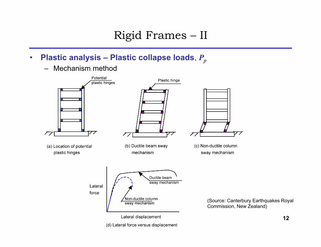
(Source: Canterbury Earthquakes Royal Commission, New Zealand)
13
Rigid Frames – II
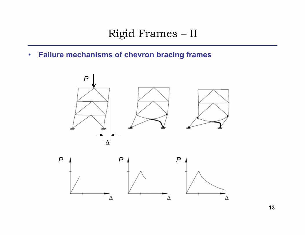
• Failure mechanisms of chevron bracing frames
P
P P P
Δ
14
Rigid Frames – II
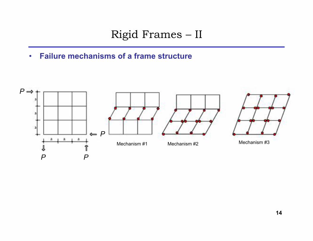
• Failure mechanisms of a frame structure
P
P
PP
Mechanism #1 Mechanism #2 Mechanism #3
15
Rigid Frames – II
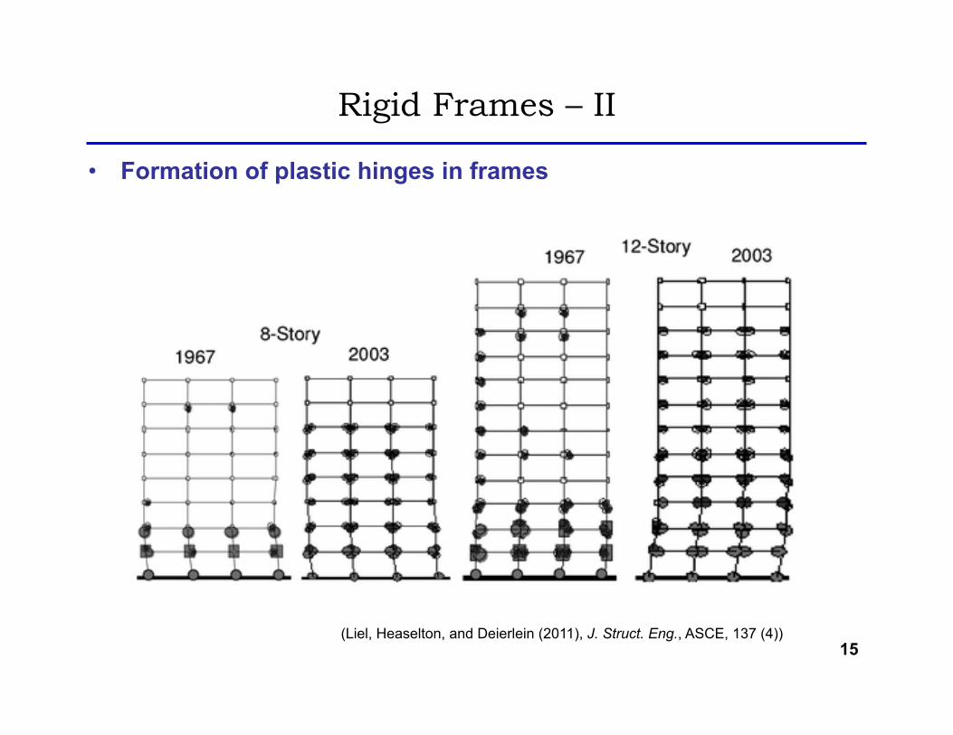
• Formation of plastic hinges in frames
(Liel, Heaselton, and Deierlein (2011), J. Struct. Eng., ASCE, 137 (4))
16
Rigid Frames – II
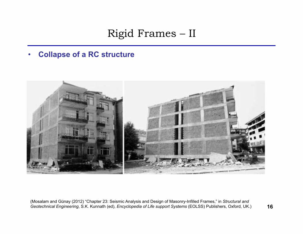
• Collapse of a RC structure
(Mosalam and Günay (2012) “Chapter 23: Seismic Analysis and Design of Masonry-Infilled Frames,” in Structural and Geotechnical Engineering, S.K. Kunnath (ed), Encyclopedia of Life support Systems (EOLSS) Publishers, Oxford, UK.)
• In the elastic stability analysis, we can determine the elastic critical load (Pcr) by – The differential equation method – The slope-deflection method – The matrix stiffness method (not covered)
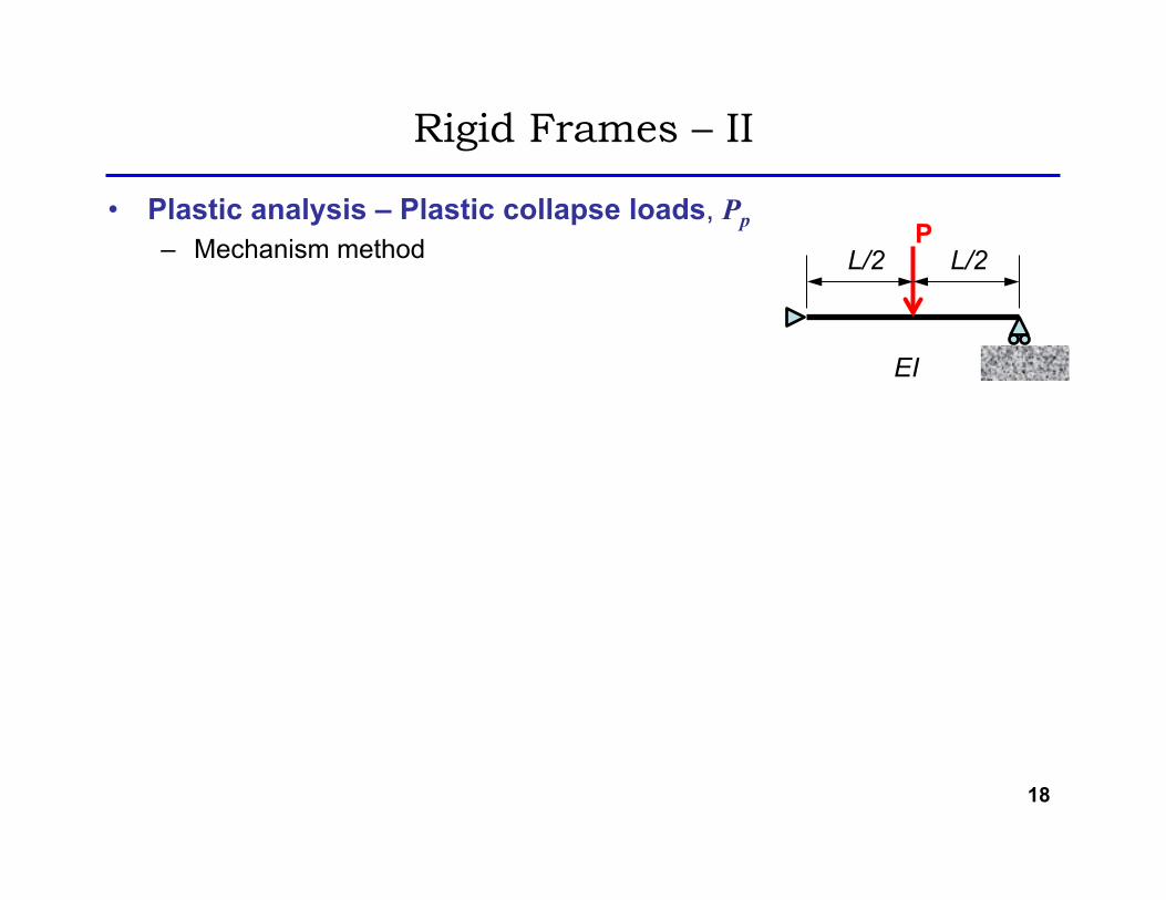
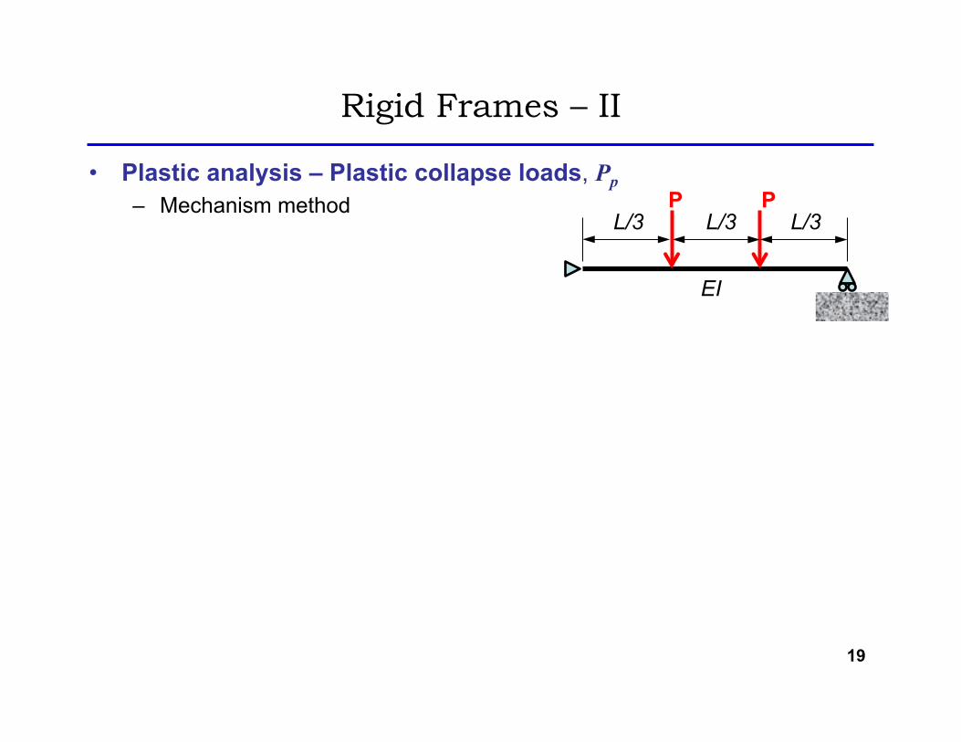
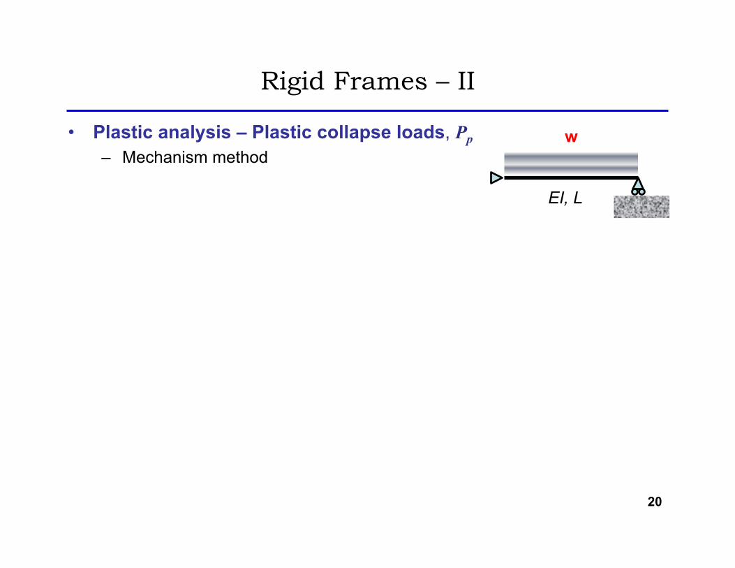
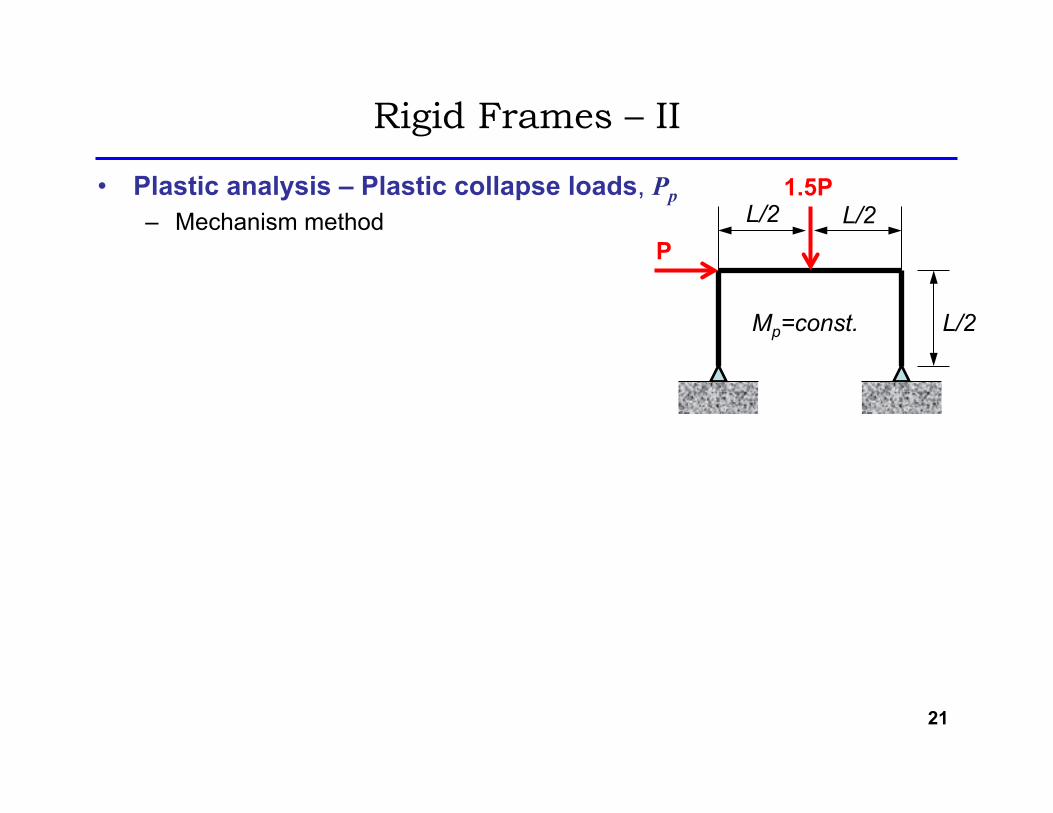
• In the plastic stability analysis, we can determine the plastic collapse load (Pp) by – The hinge-by-hinge method – The mechanism method
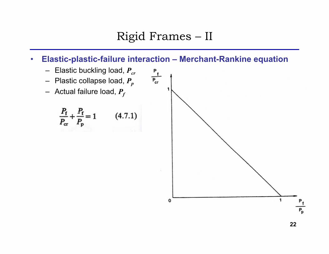
• Actual failure load (Pf) can be estimated by the Merchant-Rankine equation.
• In most cases, collapse of structures is a result of an interaction of the effects of instability and plasticity.