31
Building your application with security in mind Guide to embedded security ti.com/security

Building your applicationwith security in mind
Guide to embedded secur i ty
ti.com/security
Texas Instruments Guide to embedded security page 2
Chapter 1: Introduction to cybersecurity
1.1. Why does security matter?
1.2. Security framework: view of a typical embedded application
Chapter 2: Risk assessment and security discovery process
2.1. Threats or threat modeling (attackers capabilities and attack surfaces)
2.2. Map your security measures to security enablers
2.3. Security discovery process examples
2.4. Selecting the appropriate device
Chapter 3: How to implement security
3.1. Terminology
3.2. Detailed security goals and definitions
3.3. Elements for building an embedded application with security features
Chapter 4: Threats and adversaries
4.1. Network threats
4.2. Board threats
4.3. Chip threats
4.4. Some examples of consequences of poor security
4.5. Leveraging industry standards and specifications for security
Chapter 5: TI and security
5.1. A long history
Chapter 6: Overview of TI solutions to help
implement security measures
6.1. SimpleLink™ Bluetooth® low energy
6.2. SimpleLink Sub-1 GHz
6.3. SimpleLink Wi-Fi®
6.4. C2000
6.5. SimpleLink MSP432™ MCUs
6.6. MSP430™ MCUs
6.7. Processors
6.8. Auto processors
Conclusion
Appendix
8.1. Resources
Texas Instruments Guide to embedded security page 3
Security is paramount in our increasingly connected and complex world. Security and cybersecurity have
become top concerns and gained a lot of international attention through news reports of recent attacks
and data breaches. These events have underscored the need for designers to improve security from
endpoint to endpoint.
Looking at the Internet of Things (IoT) for instance, security is necessary in industrial applications like
building and home automation, smart grids, appliances, factory automation, personal electronics and
automotive. Designers must take security seriously, conducting a thorough risk evaluation and selecting
appropriate measures so that their application protects user privacy and defends consumers against
fraudulent actions – all while providing the proper functionality and services.
In this context, the question arises: How do you achieve your desired level of security in connected
devices? Achieving a sufficiently good level of security requires a lot of effort, investment and time.
This e-book will provide an overview of why security matters, how to evaluate which security measures
you need, and how to implement these measures against threats and adversaries. We will also take
a look at the main security enablers that Texas Instruments (TI) offers to assist you in furthering your
security objectives.
In t roduct ion

Texas Instruments Guide to embedded security page 4
As the world continues to seek greater convenience, the
internet and the devices connected to it have become a
predominant tool in our lives. However, this connection
to the internet comes with a range of drawbacks that are
somewhat tolerable – such as a partial loss of data on
social media, or not – like the loss of personal information
and privacy. Preserving privacy also means preserving
human rights and freedom, which is why cybersecurity has
become a major concern for many types of applications,
especially those that connect to the internet or to each other.
Cybersecurity is no longer something that only concerns a
small group of experts. It concerns us all and has spread into
nearly every corner of daily life. All designs requiring security
or involving some aspect of security must be taken seriously
(and with a lot of humility) from the very first day of a project.
While integrated circuits (ICs) like microcontrollers (MCUs),
processors and wireless connectivity devices do not
constitute a complete solution for securing an application,
they can provide the building blocks for you to use to
incorporate security features into your application. These
are various types of security features that enable and assist
designers in reducing the security risk consistent with their
intended end application and design requirements. At TI,
we have partitioned these features into 12 categories in
order to help our customers easily identify the security
features that are pertinent to their applications. We call
these categories “security enablers”.
1.1. Why does security matter?
Why should system architects, designers and engineers
concern themselves with the security of the products
they create?
When designers think about the word “security,” there
are inevitably other terms that come to mind, such as
“privacy,” “safety,” “protection” and “defense.” The broad
topic of security actually encompasses and embraces all of
these other terms. To maintain privacy, consumers create
passwords for online accounts, establish PINs for payment
cards and give fingerprints to prove their identity. These
actions are intended to “secure” personal information, or in
some cases to “secure” individuals or property from harm.
Anything precious and valuable is worth securing. But
an obvious question arises: From whom or what are we
securing these precious items? In the modern world,
security measures are intended to defend against other
people. This type of security is both a unique human need
and a unique human problem because, while obvious, tems
of value to one person are likely to be items of value to
many others.
Chapter 1: Introduction to cybersecurity
Security enabler: A category of security features that TI devices may support. They can help customers achieve
their security objectives. A “security enabler” is a hardware feature, such as silicon or software in-ROM.

Texas Instruments Guide to embedded security page 5
In the modern digital world, many precious items have
moved from being tangible, analog things to digital bits.
For example, the money in bank accounts is just a set
of bytes in a database; photographs and favorite songs
are simply files on smartphones or computers (now more
commonly in the cloud); and communications – text
messages, chat logs, emails, voice calls, social media
posts, etc. – are all packets of digital data moving in and
around a vast digital network spanning the globe.
But these things are no less valuable just because they
are collections of bits rather than the tangible objects they
represent. Consumers value photos, music and other
data, so they try to prevent attackers from getting into
devices and modifying their content. Because individuals
value privacy and freedom from unauthorized parties
knowing what they say and who they say it to, there is a
conscious attempt to protect communications from being
intercepted. Because users want to protect their online
identity and reputation, efforts are made to prevent others
from accessing accounts and impersonating them online.
This is all security.
1.2. Security framework: a view of a typical embedded application
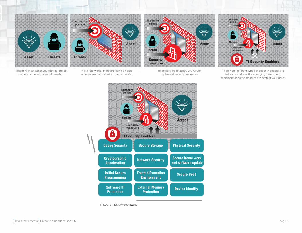
Everything starts at the application level. As shown in
Figure 1, designers will typically want to protect their
customer assets against threats by implementing security
measures. At the semiconductor level, the main assets
in a system that need protection are data, code, device
identities and keys. This e-book intends to help developers
understand how to identify their “customer assets” and
categorize them into one of these three categories at the
semiconductor level.
The exposure points (often referred to as the “attack
surface”) in a system can increase the vulnerability of
assets at each part of the application/system life cycle and
operations. Exposure points in a system can be broadly
categorized as storage, run-time or transfer operations.
TI offers security enablers in order to help designers
implement their security measures. Based on the assets
that need protection and the exposure points, you should
consider all of the appropriate security enablers and
then select security features at the device level to design
appropriate protection. The green blocks in on the next
page are 12 security enablers that we will define in the
next section.
Assets: The objects (either physical or logical) that you
want to protect. An asset can be firmware that a user
loads onto a device, data transmitted over a network or
key material stored on a device.
Texas Instruments Guide to embedded security page 6
TI delivers different types of security enablers tohelp you address the emerging threats and
implement security measures to protect your asset.
To protect those asset, you would implement security measures.
In the real world, there are can be holesin the protection called exposure points.
It starts with an asset you want to protectagainst different types of threats.
Asset
Asset
Threats
Exposure points
Threats
Asset
Exposure points
AssetThreats
Securitymeasures
Exposurepoints
Threats
Securitymeasures
TI Security Enablers
Asset
Exposurepoints
Threats
Securitymeasures
TI Security Enablers
Secure frame workand software update
Figure 1 - Security framework.
Texas Instruments Guide to embedded security page 7
Chapter 2: Risk assessment and security discovery process
It’s safe to assume that someone with sufficient motivation,
expertise, equipment and time can break any security
measure. With this in mind, a discussion on security
requirements must weigh the cost and effort of implementing
security against the value of what is being secured and the
assumed cost of mounting a successful attack.
A risk assessment should consist of two steps: a qualitative
risk assessment first (identifying the vulnerabilities, threats,
threat probabilities and measures) and a quantitative risk
assessment (quantifying loss in case a threat is realized,
such as mapping a dollar amount to a specific risk).
This principle revolves around three fundamental questions:
• What is being protected? (asset)
• Who or what are you protecting against?
(threat and threat probability)
• What is the attack surface?
(exposure points and threat probability)
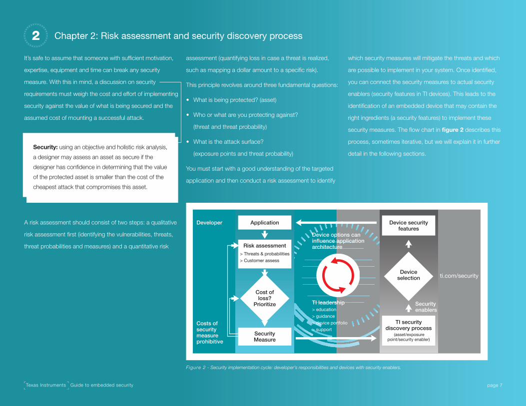
You must start with a good understanding of the targeted
application and then conduct a risk assessment to identify
which security measures will mitigate the threats and which
are possible to implement in your system. Once identified,
you can connect the security measures to actual security
enablers (security features in TI devices). This leads to the
identification of an embedded device that may contain the
right ingredients (a security features) to implement these
security measures. The flow chart in figure 2 describes this
process, sometimes iterative, but we will explain it in further
detail in the following sections.Security: using an objective and holistic risk analysis,
a designer may assess an asset as secure if the
designer has confidence in determining that the value
of the protected asset is smaller than the cost of the
cheapest attack that compromises this asset.
Figure 2 - Security implementation cycle: developer’s responsibilities and devices with security enablers.
ApplicationDeveloper
Costs ofsecuritymeasureprohibitive
Device options caninfluence applicationarchitecture
TI leadership> education> guidance> device portfolio> support
Securityenablers
Risk assessment> Threats & probabilities> Customer assess
Cost ofloss?
Prioritize
SecurityMeasure
Device securityfeatures
Deviceselection
TI securitydiscovery process
(asset/exposurepoint/security enabler)
ti.com/security

Texas Instruments Guide to embedded security page 8
2.1. Threats or threat modeling (attackers capabilities and attack surfaces)
A practical way to classify the type of threats that any
design has to consider is to view it from a system access
perspective. The attacker poses three main types of
threats: from the network (remote: internet), the board
(close proximity) and the chip (physical attacks) as shown
in figure 3.
• Network threats include any communication channel
(either wired or wireless) that allows a remote attacker
not present at the location or in close proximity to the
device to attack it.
• Board threats target printed circuit board (PCB) access
and use any wired interface on the chip.
• Chip threats infiltrate device access to perform integrated
circuit (IC) decapsulation and deprocessing to gain
access to the internal layers and elements of the chip.
See table 1 for the full definition of these threats.
Threats differ based on the level of access and the level of
equipment and capabilities attackers might have (attack
surface and attack vector). Each level simply refers to
particular attack surfaces and vector sets that you need to
consider. The types help you quickly determine the
resistance goals of particular applications and tailor which
security measures to implement. For example, chip threats
are typically not considered for connected products, as
the scariest attack for that type of product is one that
can be reproduced and scaled to many devices, potentially
an entire area/city.
Figure 3 - Threat types in an embedded system.
Wi-Fi®LAN, WANExternal
memories
Board PowerSupply
DebugIF
SerialIF
Bluetooth®,Sub-1GHz
Network
Exposure point(attack surface)
Network threats
Board threats
Chip threats
Run-timeMemories
Peripherals
Chip
Threat Categories
Threat Definition Capabilities
Network Signal analyst with only remote access, wired or wireless (no direct physical access).
The attacker accesses the system through the wide area network (WAN) or other wireless protocol. It can communicate with the device, impersonate another device, etc. The attacker can also be located in close proximity to the device. It can monitor or modify inbound/outbound wireless communication/or unintended emissions. It can attack the wireless physical layer. It can also perform network timing attacks.
Board Hobbyist or electrical engineering lab with physical access to device.
The attacker has access to the PCB. They can monitor interactions with the device using wired interfaces for communication (Serial Peripheral Interface [SPI], Inter-Integrated Circuit (I2C), universal asynchronous receiver transmitter (UART)), debugging (Joint Test Action Group [JTAG]) or power supply (electromagnetic/power analysis). They can also trace and manipulate the wired interfaces of the device. They will modify the PCB and actively try to create the conditions that lead to the targeted access retrieval.
Chip Professional hacking companies, universities, lab, spy agencies.
The attacker has a sufficient amount of time and full physical access to the product. They can delay a package to get access to the device’s internal layers. In this category, the main examples of attacks are microprobing, fault attack (laser, light, etc.) and reverse engineering of the read-only memory (ROM). The attacker delays the package to access the device’s internal layers and uses a panoply of sophisticated silicon analysis tools: focus ion beam (FIB), scanning electron microscope (SEM), EmiScope (EMI) or atomic force microscope (AFM).
Table 1 - Threat categories.

Texas Instruments Guide to embedded security page 9
If the cost of a system attack is higher than the total value of
the asset, then it is reasonable to assume that a successful
attack will not be mounted. When considering such risks,
note that some attacks are expensive to develop but can
be inexpensive to repeat. For example, an attack that relies
on backgrinding and observing the active components
to extract assets from a device requires both significant
expertise and equipment to execute, and this expertise and
equipment is required each time the attack is repeated.
In contrast, there are attacks that obtain an invariant
secret used in a device family to unlock it for retest or
failure analysis purposes. Obtaining the secret may involve
equipment and expertise rivaling the first attack in cost;
however once obtained, the secret may be used to mount
repeated attacks, making this effectively very low cost
compared to acquiring access to the whole system. This
attack presents a high risk.
There are many techniques for analyzing security risks.
Generally, within the security space, risk analysis techniques
are referred to as “threat modeling.” Each risk analysis
technique comes with its own pros and cons, in addition to
specific industry standards (official or de facto) that specify
which technique(s) to use. We provide further details and
possible methods in Section 3.3 to help designers carry out
this threat modeling step in a more rigorous way.
In the threat modeling process, it is very common that the
identification of threats leads to the identification of assets,
and vice versa. For example, you may not consider a piece
of software an asset, but when considering the threats
when a device is connected, that piece of software could
be updated, which would lead to the control of all devices
in the network; therefore, a piece of software and its control
suddenly becomes a very important asset.
table 2 shows three different scenarios that use the TI
security discovery process. This process should guide
you towards the security enablers that are most relevant
to your security objectives, but it does not replace a full
analysis (following one of the possible tools we suggest in
Section 3.3).
Defining the security measure is a necessary step to identify
the security enablers you need at the device level.
Scenarios Baby MonitorPayment Terminal (Electronic Point of Sale [ePOS]) Electronic Door Lock (E-Lock)
Threat Attackers can eavesdrop and access the video/audio of a baby monitor to determine if someone is home.
Attackers can try to physically access a system to manipulate what is displayed, in order to deceive users and steal money.
Attackers can use the debugging interface to access the code and key in order to understand how to open any e-lock of any brand.
Customer Asset Video/audio streaming content
Money (data displayed). Personal possessions (anything that the e-lock protects).
Security Measure Encrypt video/audio streaming content.
Add tamper protection to the PCB with a mesh.
Lock the debugging port.
Table 2 - TI security discovery process examples.

Texas Instruments Guide to embedded security page 10
2.2. Map your security measures to security enablers
Now that you have identified your threats, your (application-
level) assets and your security measures, you can map these
security measures to the security enablers. We provide this
as a tool (table 4) to facilitate your device selection process.
The 12 categories of security enablers (the green boxes
in figure 1) are somewhat flexible and purposely include
overlap. Each category may include dozens of detailed
features that help resolve a security threat for a particular
market or application. In general, most TI embedded
processing systems-on-chip (SoCs) contain at least
some basic security enablers, such as secure boot and
cryptographic acceleration, on-chip. Some security enablers
are only available on specific SoCs, depending on the
device’s intended applications. Figure 4 places the security
enablers in a pyramid to illustrate the typical layers of an
embedded processor/MCU with or without a wireless
interface. We recommend starting from the bottom of the
pyramid and working toward the top as a typical way to
think about the relevant measures.
Figure 4 - Typical layers of an embedded processor, with or without a wireless interface.
Physicalsecurity
Physicalsecurity
Secure frame workand software update
Initial secureprogramming
Software IPprotection
Software and keyprovisioning security
Run-time security
Foundation for security
Debug security
Deviceidentity and keys
Secure boot Cryptographicacceleration
Secure storage Network security
Trusted executionenvironment
External memoryprotection
Texas Instruments Guide to embedded security page 11
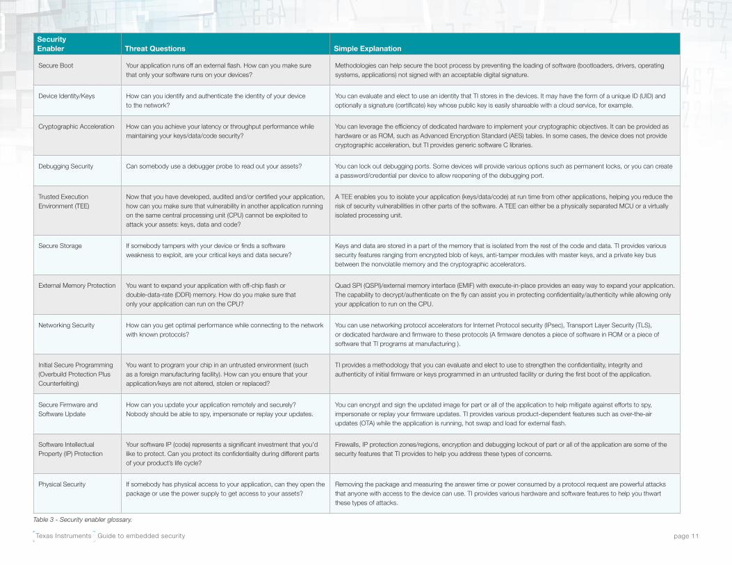
Security Enabler Threat Questions Simple Explanation
Secure Boot Your application runs off an external flash. How can you make sure that only your software runs on your devices?
Methodologies can help secure the boot process by preventing the loading of software (bootloaders, drivers, operating systems, applications) not signed with an acceptable digital signature.
Device Identity/Keys How can you identify and authenticate the identity of your device to the network?
You can evaluate and elect to use an identity that TI stores in the devices. It may have the form of a unique ID (UID) and optionally a signature (certificate) key whose public key is easily shareable with a cloud service, for example.
Cryptographic Acceleration How can you achieve your latency or throughput performance while maintaining your keys/data/code security?
You can leverage the efficiency of dedicated hardware to implement your cryptographic objectives. It can be provided as hardware or as ROM, such as Advanced Encryption Standard (AES) tables. In some cases, the device does not provide cryptographic acceleration, but TI provides generic software C libraries.
Debugging Security Can somebody use a debugger probe to read out your assets? You can lock out debugging ports. Some devices will provide various options such as permanent locks, or you can create a password/credential per device to allow reopening of the debugging port.
Trusted Execution Environment (TEE)
Now that you have developed, audited and/or certified your application, how can you make sure that vulnerability in another application running on the same central processing unit (CPU) cannot be exploited to attack your assets: keys, data and code?
A TEE enables you to isolate your application (keys/data/code) at run time from other applications, helping you reduce the risk of security vulnerabilities in other parts of the software. A TEE can either be a physically separated MCU or a virtually isolated processing unit.
Secure Storage If somebody tampers with your device or finds a software weakness to exploit, are your critical keys and data secure?
Keys and data are stored in a part of the memory that is isolated from the rest of the code and data. TI provides various security features ranging from encrypted blob of keys, anti-tamper modules with master keys, and a private key bus between the nonvolatile memory and the cryptographic accelerators.
External Memory Protection You want to expand your application with off-chip flash or double-data-rate (DDR) memory. How do you make sure that only your application can run on the CPU?
Quad SPI (QSPI)/external memory interface (EMIF) with execute-in-place provides an easy way to expand your application. The capability to decrypt/authenticate on the fly can assist you in protecting confidentiality/authenticity while allowing only your application to run on the CPU.
Networking Security How can you get optimal performance while connecting to the network with known protocols?
You can use networking protocol accelerators for Internet Protocol security (IPsec), Transport Layer Security (TLS), or dedicated hardware and firmware to these protocols (A firmware denotes a piece of software in ROM or a piece of software that TI programs at manufacturing ).
Initial Secure Programming(Overbuild Protection Plus Counterfeiting)
You want to program your chip in an untrusted environment (such as a foreign manufacturing facility). How can you ensure that your application/keys are not altered, stolen or replaced?
TI provides a methodology that you can evaluate and elect to use to strengthen the confidentiality, integrity and authenticity of initial firmware or keys programmed in an untrusted facility or during the first boot of the application.
Secure Firmware and Software Update
How can you update your application remotely and securely? Nobody should be able to spy, impersonate or replay your updates.
You can encrypt and sign the updated image for part or all of the application to help mitigate against efforts to spy, impersonate or replay your firmware updates. TI provides various product-dependent features such as over-the-air updates (OTA) while the application is running, hot swap and load for external flash.
Software Intellectual Property (IP) Protection
Your software IP (code) represents a significant investment that you’d like to protect. Can you protect its confidentiality during different parts of your product’s life cycle?
Firewalls, IP protection zones/regions, encryption and debugging lockout of part or all of the application are some of the security features that TI provides to help you address these types of concerns.
Physical Security If somebody has physical access to your application, can they open the package or use the power supply to get access to your assets?
Removing the package and measuring the answer time or power consumed by a protocol request are powerful attacks that anyone with access to the device can use. TI provides various hardware and software features to help you thwart these types of attacks.
Table 3 - Security enabler glossary.

Texas Instruments Guide to embedded security page 12
Having identified threats and security measures at the
application level, it’s time to identify the corresponding
assets and exposure points at the semiconductor level,
using table 4 as a guide to select the most appropriate
security enablers.
For example, looking at table 4, if you wish to protect the
asset Code in the situation (exposure point) of Transfer,
you will most likely need to consider the Cryptographic
Acceleration, Networking Security, Secure Firmware and
Software Update, and Initial Secure Programming security
enablers. If you want to protect the Identity & Keys asset
in the situation (exposure point) of Transfer, you will most
likely need to consider the Cryptographic Acceleration and
Networking security enablers.
It’s likely that only one (or only a subset) of the securities
enablers provided above are pertinent to the problem you
are trying to solve. Additional security enablers, outside
those provided above, may be necessary to complete the
solution. At best, table 4 can help you make a first initial
assessment of the possible important security enablers to
help you through the selection process.
TI Security Enablers
Secure Boot
Device Identity/Keys
Cryptographic Acceleration
Debugging Security
TEE
Secure Storage
External Memory Protection
Networking Security
Initial Secure Programming
Secure Firmware and Software Update
Siftware IP Protection
Physical Security
Table 4 - Guide to security enablers based on function of asset and exposure points.
Texas Instruments Guide to embedded security page 13
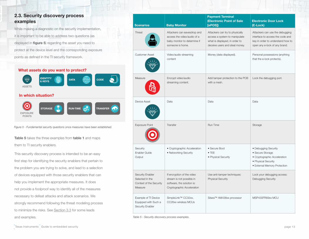
2.3. Security discovery process examples
While making a diagnostic on the security implementation,
it is important to be able to address two questions (as
displayed in figure 5) regarding the asset you need to
protect at the device level and the corresponding exposure
points as defined in the TI security framework.
Table 5 takes the three examples from table 1 and maps
them to TI security enablers.
This security discovery process is intended to be an easy
first step for identifying the security enablers that pertain to
the problem you are trying to solve, and lead to a selection
of devices equipped with those security enablers that can
help you implement the appropriate measures. It does
not provide a foolproof way to identify all of the measures
necessary to defeat attacks and attack scenarios. We
strongly recommend following the threat modeling process
to minimize the risks. See Section 3.3 for some leads
and examples.
Scenarios Baby Monitor
Payment Terminal (Electronic Point of Sale [ePOS])
Electronic Door Lock (E-Lock)
Threat Attackers can eavesdrop and
access the video/audio of a
baby monitor to determine if
someone is home.
Attackers can try to physically
access a system to manipulate
what is displayed, in order to
deceive users and steal money.
Attackers can use the debugging
interface to access the code and
key in order to understand how to
open any e-lock of any brand.
Customer Asset Video/audio streaming
content
Money (data displayed). Personal possessions (anything
that the e-lock protects).
Measure Encrypt video/audio
streaming content.
Add tamper protection to the PCB
with a mesh.
Lock the debugging port.
Device Asset Data Data Data
Exposure Point Transfer Run Time Storage
Secuirty
Enabler Guide
Output
• Cryptographic Acceleration
• Networking Security
• Secure Boot
• TEE
• Physical Security
• Debugging Security
• Secure Storage
• Cryptographic Acceleration
• Physical Security
• External Memory Protection
Security Enabler
Selected in the
Context of the Security
Measure
If encryption of the video
stream is not possible in
software, the solution is:
Cryptographic Acceleration
Use anti-tamper techniques:
Physical Security
Lock your debugging access:
Debugging Security
Example of TI Device
Equipped with Such a
Security Enabler
SimpleLink™ CC32xx,
CC26xx wireless MCUs
Sitara™ AM438xx processor MSP430FR69xx MCU
Table 5 - Security discovery process examples.
Figure 5 - Fundamental security questions once measures have been established.
What assets do you want to protect?
ASSETS
EXPOSUREPOINTS
In which situation?
IDENTITY& KEYS
Texas Instruments Guide to embedded security page 14
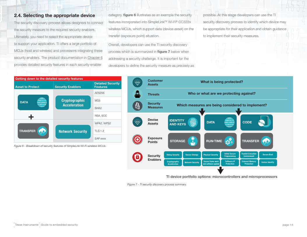
2.4. Selecting the appropriate device
The security discovery process allows designers to connect
the security measure to the required security enablers.
Ultimately, you need to select the appropriate device
to support your application. TI offers a large portfolio of
MCUs (host and wireless) and processors integrating these
security enablers. The product documentation in Chapter 6
provides detailed security features in each security enabler
category. figure 6 illustrates as an example the security
features incorporated into SimpleLinkTM Wi-Fi® CC322x
wireless MCUs, which support data (device asset) on the
transfer (exposure point) situation.
Overall, developers can use the TI security discovery
process which is summarized in figure 7 below when
addressing a security challenge. It is important for the
developers to define the security measure as precisely as
possible. At this stage developers can use the TI
security discovery process to identify which device may
be appropriate for their application and obtain guidance
to implement their security measures.
Getting down to the detailed security features
Asset to Protect Security EnablersDetailed Security Features
AES256
MD5
SHA2
RSA, ECC
WPA2, WPS2
TLS 1.2
EAP xxxx
+
Figure 6 - Breakdown of security features of SimpleLink Wi-Fi wireless MCUs.
Figure 7 - TI security discovery process summary.
What is being protected?
Who or what are we protecting against?
Which measures are being considered to implement?
TI device portfolio options: microcontrollers and microprocessors
IDENTITYAND KEYS DATA CODE
RUN-TIMESTORAGE TRANSFER
CustomerAssets
Threats
SecurityMeasures
DeviseAssets
ExposurePoints
SecurityEnablers Secure frame work
and software update
DATA

Texas Instruments Guide to embedded security page 15
Chapter 3: How to implement security
3.1. Terminology
It is critical to ensure consistent communications around
embedded systems security, especially when there are
different definitions for the terms used. Inconsistency –
where all parties were sure they understood the security
discussions – leads to preventable failures. Therefore,
consistent definitions and terminology are required.
Security: Using an objective and holistic risk analysis, a
designer may assess an asset as secure if the designer has
confidence in determining that the value of the protected
asset is smaller than the cost of the cheapest attack that
compromises this asset
Asset: The objects (either physical or logical) that you want
to protect. An asset can be firmware that a user loads onto
a device, data transmitted over a network or key material
stored on a device. The three main categories are:
• Key and device identity: Keys used for any
cryptographic operations. Device identity can comprise
one (or more) unique number(s), key(s) or certificate(s).
• Data: Any data that could represent value to an attacker.
• Code: Any software code that could represent value
to an attacker.
Security boundaries: System and SoC boundaries define
the limit between an assumed trusted world and a non-
trusted world. These boundaries can be static or dynamic:
• Dynamic: To receive and apply an over-the-air patch,
there needs to be trusted communications channels
established between the patch source and destination.
This may exist only during the transfer of the patch.
• Static: The trusted transmission of instructions from
on-chip static random access memory (SRAM) or flash
memory to the CPU instruction decoder may be static
trusted (always trusted).
Trusted: Firm confidence that an entity provides the security
goals it claims, and behaves as expected.
Threat: Also known as a “threat model.” Threats consist of
a person or organization with sufficient motivation, expertise,
equipment and time to carry out an attack, as well as the
means to gain access. It is the nature of the attack vector
that determines the specifics in how much expertise,
equipment and time the attack requires.
Exposure points: Points in a system where there could be
a risk of attack or a way of entry. Also known as an “attack
surface.” If a burglar were attacking a house, the exposure
point in that case is the door. The three categories in the TI
framework are:
• Storage: Keys, data or code potentially exposed at rest in
external or internal chip memory.
• Run time: Keys, data or code potentially exposed during
run-time operations of the application.
• Transfer: Keys, data or code potentially exposed during
transfer from/to a remote location. The transfer could be
eavesdropped, intercepted or impersonated.
Attack vector: The mechanism used to carry out the attack.
If a burglar were attacking a house, the attack vector is the
burglar picking the lock of the door.
Vulnerability: A weakness in the system that can potentially
be exploited. In the burglar analogy, this could be a defect in
the lock of the door.
Exploit: A weakness of the system that can be exploited.
Security measures: Measures aimed at providing the
intended protection of certain assets against specific threats.

Texas Instruments Guide to embedded security page 16
3.2. Detailed security goals and definitions
As we stated earlier, assets describe the objects (either
physical or logical) that you want to protect. An asset can
be firmware that a user loads onto a device,
data transmitted over a network or key material stored
on a device.
Along with defining the asset, you must also define its
security attributes. This is essentially the type of security
that could be appropriate to protect an asset. For
example, software code may be open and only need
protection from modification, or a serial interface may be
critical to the system and exposed, so it may need key
exchange and encryption.
Some code may be deemed proprietary and require
significant efforts to keep it confidential.
Table 7 lists the most common security attributes/goals.
By narrowing the definition of assets that may need
protection and limiting the set of security attributes to only
those you strictly need, you can focus your security efforts
to those areas where you can gain the most value.
3.3. Elements for building an embedded application with security features
Using the security terms defined within this e-book, you can
assess your system goals by considering three questions
for each identified asset in the system:
• What security attributes does the asset need?
• What threats do I need to protect the asset against?
• What confidence is needed in that protection?
This section gives you a starting point with which to focus
your analysis of possible attack vectors, as well as deciding
whether your security requirements are too stringent or if a
system design effort is required to reduce the overall risk.
Consider a utility metering system (gas, electric, heat)
using a global symmetrical master key for administration
purposes. The system requires high level of assurance that
its key is protected from chip-, board- and network-level
threats. High confidence is required in case a single device
is attacked and jeopardizes the entire metering system.
Security Attribute Definition
Confidentiality The protection of an asset is not made available or disclosed to unauthorized entities. In this context, entities include
both individuals and processes [1]. Types of authorized entities include the asset owner, end user, manufacturer or
creator, and law enforcement. Vendors may also consider customer code (binary) a confidential asset, as customers
control who can read the information.
Access Control This includes both access authorization and access restriction. It refers to all of the steps taken to selectively
authorize and restrict entry, contact or use of assets [1]. This applies to all assets from SRAM, ROM and flash
memory to control over a peripheral, clock system or simple debugging/JTAG access
Authenticity These are assets or entities (data, transactions, communications, software or documents – either electronic or
physical) confirmed as genuine, authorized to perform a task or used as intended. Authenticity is the validation that
all parties involved are who they claim to be and that data has not been modified from the original source by an
unauthorized entity.
Availability Protects assets from unauthorized loss of use (denial-of-service attacks) [2]. Loss of use includes many examples,
including swamping a communication channel, false revocation of keys, spoofing authentication-failed responses to
power-supply brownouts or failed patches, or a false patch to increase the internal revision number significantly in
order to saturate (or at least make a legitimate patch fail due to) a revision number out of sequence.
Integrity Protects assets from unauthorized modification [2]. Examples include enabling, disabling or modifying hardware
functions such as memory, peripherals, modifying keys, or random number entropy seed. Additional examples
include selecting incorrect clock sources, divisors, analog-to-digital converter (ADC) sample rate, programmable gain
amplifier (PGA) prescalers, and memory security protection. In software, some other examples comprise of patches
for authentication code, security configuration setup code or the creation of a universal master key, deviant interrupt
vector tables, setting crypto keys to known values, or adding back doors for remote exploits.
Table 7: Security attributes.
Texas Instruments Guide to embedded security page 17
Unfortunately, this might be a costly solution; a better
approach would be to have a different asymmetrical key for
each metering device.
This approach refocuses the security requirement from
a chip, board and network level threat to only a network
threat – which happens to be a much cheaper requirement
to fulfill in this case. In other words, if you use the same
symmetric key in all devices, there is a huge incentive for
attackers to retrieve that key. That is why you must consider
chip and board threats as well. But if there is a different key
(for example, a public key) per chip, then the risk is reduced
significantly, as it becomes economically not interesting for
attackers to retrieve each and every key.
Security development life cycle
Building embedded applications with security features
involves more than performing risk analysis and
implementing various security techniques and features.
TI, along with other leading technology companies, has
recognized the need for a security development life cycle
(SDL) [3] [4] [5].
An SDL comprises various practices to help improve the
security of a system or product, both at release and during
its operational lifetime. Companies have defined their own
SDL variants to address their own needs (including using
terms other than “SDL”). Consider SDL practices for all
phases of a project, including:
• Concept development/requirements generation
• Architecture
• Design
• Implementation
• Verification/validation
• Maintenance
In addition, an SDL may be implemented to provide
trainings on security-related topics (such as secure coding
techniques, cryptography usage, etc.).
Early in a project, a security assessment process should
include looking at the overall system and its individual
features to gain an understanding of where there may
be risks. Some examples of questions asked during an
assessment include:
• Does the feature store privacy-related data?
• Is the system using a new OS?
• Does the system connect to the internet?
• Does the system have features that should only be
available to some stakeholders?
The result of this assessment should be a determination
of the applicability of the SDL, and what (if any) tailoring
of the SDL.
Threat modeling
As explained in Section 2.1, threat modeling is the method
for analyzing a system for security threats and determining
how to mitigate those threats. As outlined in “Threat
Modeling: Designing for Security” by Adam Shostack, threat
modeling involves four general steps:
1. Define the system to be protected.
2. Determine what can go wrong.
3. Determine countermeasures for the things that
can go wrong.
4. Check your analysis – how good is it?
Step one involves describing the system, often using
data-flow diagrams and/or control-flow diagrams. Various
techniques can assist a development team during step two
to determine what can go wrong (how a malicious actor
can attack the system). Step three entails generating a
collection of attack possibilities, prioritizing them and putting
countermeasures in place. Step three may also result in
features changing or being dropped altogether from the
product if the security risks are deemed too severe (often
called “attack surface reduction”). Finally, step four provides
a valuable review to look for things missed in earlier steps.
Threat modeling continues to evolve. Table 8 provides
a short overview of several threat-modeling techniques,
along with information on where to find more information
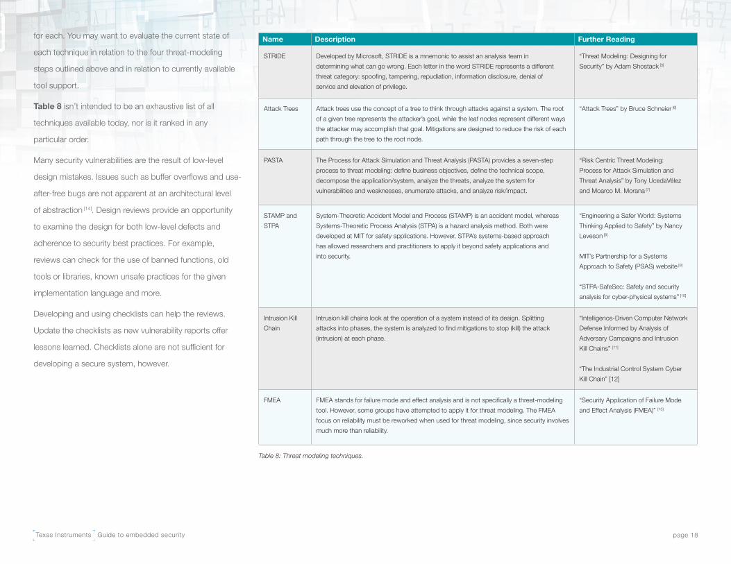
Texas Instruments Guide to embedded security page 18
for each. You may want to evaluate the current state of
each technique in relation to the four threat-modeling
steps outlined above and in relation to currently available
tool support.
Table 8 isn’t intended to be an exhaustive list of all
techniques available today, nor is it ranked in any
particular order.
Many security vulnerabilities are the result of low-level
design mistakes. Issues such as buffer overflows and use-
after-free bugs are not apparent at an architectural level
of abstraction [14]. Design reviews provide an opportunity
to examine the design for both low-level defects and
adherence to security best practices. For example,
reviews can check for the use of banned functions, old
tools or libraries, known unsafe practices for the given
implementation language and more.
Developing and using checklists can help the reviews.
Update the checklists as new vulnerability reports offer
lessons learned. Checklists alone are not sufficient for
developing a secure system, however.
Name Description Further Reading
STRIDE Developed by Microsoft, STRIDE is a mnemonic to assist an analysis team in
determining what can go wrong. Each letter in the word STRIDE represents a different
threat category: spoofing, tampering, repudiation, information disclosure, denial of
service and elevation of privilege.
“Threat Modeling: Designing for
Security” by Adam Shostack [3]
Attack Trees Attack trees use the concept of a tree to think through attacks against a system. The root
of a given tree represents the attacker’s goal, while the leaf nodes represent different ways
the attacker may accomplish that goal. Mitigations are designed to reduce the risk of each
path through the tree to the root node.
“Attack Trees” by Bruce Schneier [6]
PASTA The Process for Attack Simulation and Threat Analysis (PASTA) provides a seven-step
process to threat modeling: define business objectives, define the technical scope,
decompose the application/system, analyze the threats, analyze the system for
vulnerabilities and weaknesses, enumerate attacks, and analyze risk/impact.
“Risk Centric Threat Modeling:
Process for Attack Simulation and
Threat Analysis” by Tony UcedaVélez
and Moarco M. Morana [7]
STAMP and
STPA
System-Theoretic Accident Model and Process (STAMP) is an accident model, whereas
Systems-Theoretic Process Analysis (STPA) is a hazard analysis method. Both were
developed at MIT for safety applications. However, STPA’s systems-based approach
has allowed researchers and practitioners to apply it beyond safety applications and
into security.
“Engineering a Safer World: Systems
Thinking Applied to Safety” by Nancy
Leveson [8]
MIT’s Partnership for a Systems
Approach to Safety (PSAS) website [9]
“STPA-SafeSec: Safety and security
analysis for cyber-physical systems” [10]
Intrusion Kill
Chain
Intrusion kill chains look at the operation of a system instead of its design. Splitting
attacks into phases, the system is analyzed to find mitigations to stop (kill) the attack
(intrusion) at each phase.
“Intelligence-Driven Computer Network
Defense Informed by Analysis of
Adversary Campaigns and Intrusion
Kill Chains” [11]
“The Industrial Control System Cyber
Kill Chain” [12]
FMEA FMEA stands for failure mode and effect analysis and is not specifically a threat-modeling
tool. However, some groups have attempted to apply it for threat modeling. The FMEA
focus on reliability must be reworked when used for threat modeling, since security involves
much more than reliability.
“Security Application of Failure Mode
and Effect Analysis (FMEA)” [13]
Table 8: Threat modeling techniques.

Texas Instruments Guide to embedded security page 19
Verify the requirements resulting from a security assessment
and threat modeling via testing. While classic functional
testing techniques often apply, additional testing techniques
available for vulnerability testing include:
• Fuzz testing: Random inputs attempt to crash the
target, which an attacker can often use as a starting
point for a more useful attack.
• Static analysis using security-focused rules.
• Vulnerability scanning: Using a tool to scan a system
for known vulnerabilities, such as looking for known
vulnerabilities in a Secure Sockets Layer (SSL) library.
In addition to individual testing techniques, another common
testing methodology is called penetration testing (also
known as pen testing). Pen testing focuses on real-world
scenarios and finds ways that an attacker can circumvent
a system’s security. The effectiveness of pen testing is
often correlated to the experience of the team running
the tests. You can hire a company to perform pen testing
on a targeted product, but any selection process for a
company like this include should an evaluation of its overall
experience level, as well as its experience with the kind
of product being tested.
Unfortunately, mistakes will be made during a system’s
development. While following a solid SDL will likely reduce
the number of vulnerabilities in a system, it is unlikely
to remove all exposure points. In addition, new attack
techniques are developed regularly, which exposes
vulnerabilities that a development team could not
have foreseen.
When exposure points are exploited in the field, teams
may need to move quickly to resolve them. Planning ahead
will allow development teams to execute with precision
and speed. A response plan should generally include the
following steps:
• Identify individuals or teams responsible for executing
the response plan.
• Identify or create a path to report vulnerabilities.
• Establish a process to triage the reported vulnerabilities.
• Establish a process to analyze, close and test an
exposure point.
• Establish a process to release the fixed device and
security bulletins and manage customer relationships.
• Update training and testing to catch similar issues
in the future.

Texas Instruments Guide to embedded security page 20
Chapter 4: Threats and adversaries: The main exposure points and attack types
As depicted in figure 1, the main assets in a system that
may need protection can be categorized as data, code,
device identities and keys. The exposure points in a system
increase the vulnerability of these assets during system
operation and require different and appropriate security
features. Exposure points in a system can be broadly
categorized as storage, run-time and transfer operations.
Based on the assets needing protection and the exposure
points, consider the appropriate security features to
design protection.
From a system-access perspective, an attacker poses three
main types of threats: to the network (remote), to the board
(close proximity) and to the chip (see table 1).
4.1. Network threats
With the massive growth of connected devices, network
attacks are becoming more common. This is attributed to
a number of aspects related to the fundamental nature of
communication networks. A network topology (like that
shown in figure 8) provides an exponentially growing
number of attack paths and a growing potential to identify
an exposure point through which an attacker can reach
the target asset. Furthermore, an attack from the network
is less obvious, thus providing the attacker some level of
anonymity over a physical attack.
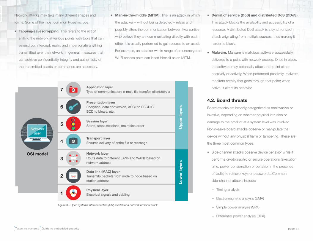
The structured nature of security protocol stacks (see
figure 9) increases the opportunity for more attacks due
to the different layers of implementation, as well as the
cross-layer glue logic. These layers are in many cases less
well-defined and more prone to implementation faults.
Figure 8 - Typical network topology.
Texas Instruments Guide to embedded security page 21
Network attacks may take many different shapes and
forms. Some of the most common types include:
• Tapping/eavesdropping. This refers to the act of
sniffing the network at various points with tools that can
eavesdrop, intercept, replay and impersonate anything
transmitted over the network. In general, measures that
can achieve confidentiality, integrity and authenticity of
the transmitted assets or commands are necessary.
• Man-in-the-middle (MITM). This is an attack in which
the attacker – without being detected – relays and
possibly alters the communication between two parties
who believe they are communicating directly with each
other. It is usually performed to gain access to an asset.
For example, an attacker within range of an unencrypted
Wi-Fi access point can insert himself as an MITM.
• Denial of service (DoS) and distributed DoS (DDoS).
This attack blocks the availability and accessibility of a
resource. A distributed DoS attack is a synchronized
attack originating from multiple sources, thus making it
harder to block.
• Malware. Malware is malicious software successfully
delivered to a point with network access. Once in place,
the software may potentially attack that point either
passively or actively. When performed passively, malware
monitors activity that goes through that point; when
active, it alters its behavior.
4.2. Board threats
Board attacks are broadly categorized as noninvasive or
invasive, depending on whether physical intrusion or
damage to the product at a system level was involved.
Noninvasive board attacks observe or manipulate the
device without any physical harm or tampering. These are
the three most common types:
• Side-channel attacks observe device behavior while it
performs cryptographic or secure operations (execution
time, power consumption or behavior in the presence
of faults) to retrieve keys or passwords. Common
side-channel attacks include:
– Timing analysis
– Electromagnetic analysis (EMA)
– Simple power analysis (SPA)
– Differential power analysis (DPA)
Networkuser
Application layerType of communication: e-mail, file transfer, client/server
Presentation layerEncrytion, data conversion, ASCII to EBCDIC, BCD to binary, etc.
Session layerStarts, stops sessions, maintains order
Transport layerEnsures delivery of entire file or message
Network layerRouts data to different LANs and WANs based on network address
Data link (MAC) layerTransmits packets from node to node based on station address
Physical layerElectrical signals and cabling
OSI model
7
6
5
4
3
2
1
Upp
er la
yers
Low
er la
yers
Figure 9 - Open systems interconnection (OSI) model for a network protocol stack.
Texas Instruments Guide to embedded security page 22
• Fault-injection attacks alter environmental and operating
conditions to cause the device to malfunction in a way
that compromises security (such as skipping a critical
CPU instruction or erasing bits that defeat device
debugging locks). Common methods include:
– Altering voltages to introduce glitches.
– Varying the supply voltage beyond the
operating limits.
– Altering the device temperature below or above
its operating limits.
– Altering clocking to damage external crystals.
– Sending too-short clock pulses.
• Software attacks launch through communication
interfaces with the device. Device debugging (JTAG) or
other programming interfaces are the most common
targets, like bootloaders, vendor-proprietary interfaces
and protocols, and serial data communication interfaces
like I2C, UART, SPI, QSPI and EMIF.
Invasive board attacks involve physical intrusion at a
product or system level. This includes intrusion of product
enclosures or tamper-protected enclosures (like PCB
tamper mesh).
4.3. Chip threats
Chip threats enable unauthorized access beyond just the
board signals, reaching into the chip’s internal signals
in an effort to retrieve on-chip nonvolatile memory. The
information gained can be the end goal itself. For instance,
if an attacker obtains user code stored in on-chip flash
and understands the application board schematics, they
can clone and sell the application itself on the counterfeit
market without the laborious and expensive R&D work.
Alternatively, searching the same flash image for run-time
weaknesses or encryption keys reveals vulnerability to
a network attack. Once discovered, this network
attack can be launched remotely to cause harm or
steal further secrets.
Decapsulating the package, observing photons emitted by
transistors using emission microscopy (EMMI), manipulating
security bits with a laser, cutting security signals with a
focused ion beam (FIB), nanoprobing data lines, imaging
the back side of flash contents with a scanning electron
microscope (SEM), and deprocessing and reverse-
engineering the device circuit layers are just a few examples
of chip threats. The level of special knowledge, motivation,
skill and cost required to carry out chip attacks varies,
but in general is much greater than electrical attacks to
the board.
4.4. Consequences of poor security
To provide some real-world context to the abstract
question of why security matters, it’s important to consider
and discuss five situations where security mechanisms
have failed.
• Using a common password for a large number
of devices. It is unfortunately all-too-common in the
design of a system that convenience takes precedence
over security. From a consumer standpoint, it is not
uncommon to see people using the same password or
PIN across various accounts, devices and websites.
Cybersecurity practitioners make the same mistake
when it comes time to design a key management
system and infrastructure. Developers often opt for an
approach based on a common key rather than using a
different key per system, device or endpoint because
it is more convenient and cheaper. Such a mistake has
led to some rather large-scale attacks. For example,
well-publicized internet DDoS attacks in 2016 came as
a result of consistent default passwords on some IoT
embedded systems. Because system owners didn’t
modify the default password before adding it to the
network, hundreds of thousands of devices were quickly
taken over and made part of a malicious botnet [15].
Texas Instruments Guide to embedded security page 23
• Using a proprietary algorithm and security by
obscurity. A second example is using proprietary
algorithms for cryptography. Standard, industry-
accepted algorithms have received the proper attention,
testing and study before becoming a standard. The
entire cryptographic community constantly attacks and
reviews these standards to ensure that they continue to
withstand scrutiny. In many instances, when proprietary
algorithms are finally publicly known (due to reverse-
engineering or another source of leakage), they are easily
and very quickly undermined and broken by the same
cryptographic community. A few more notorious failures
from the embedded systems space are Keeloq and
HiTag2 [16] [17].
According to Kerckhoff’s principle, one of the
fundamental principles in security is that a cryptosystem
should be secure even if everything about the system
(except the key) is public knowledge. Cryptographer
and engineer Claude Shannon once said, “One ought to
design systems under the assumption that the enemy
will immediately gain full familiarity with them.” But just
because “one ought to design” a secure system with
that mindset does not mean that system designers
should help attackers gain that familiarity. Keeping
implementation details secret can buy you quite a lot
of time – maybe even years, but it should never be the
main pillar of security.
• In-field firmware updates gone wrong. In-field
firmware updates have enabled new firmware images
to be downloaded and installed into devices already
deployed in the field, providing an effective way for
manufacturers to offer service and support for their
products after leaving the factory. However, in the
absence of proper security measures, this feature
may be misused. The consequences of a successful
exploitation can be disastrous, ranging from a loss of IP
and product cloning all the way to attackers successfully
completing a takeover of the deployed systems.
For example, if a medicine pump does not verify the
authenticity of new firmware images, a successful
exploitation of the firmware update mechanism could
potentially allow attackers to change or control the
dosage delivered to a patient and alter the pump’s
display screen to indicate that a dosage was delivered[18].
In this scenario, failure to secure the device’s firmware
upgrade process could contribute to the device not
functioning as intended.
• Interconnected system complexity leads to failure.
Large, complex and interconnected systems can make
it extremely difficult to discover and close security gaps.
This is becoming more common as engineers connect
more embedded systems to the internet each day.
Consider the case of an internet-connected vehicle.
Automotive manufacturers like this idea because it
allows them to remotely collect diagnostic and usage
information; meanwhile, it can also be another potential
revenue stream, allowing a service like in-vehicle Wi-Fi
hotspots. New car buyers are attracted to these types of
services since they enable features like automatic crash
notification to emergency services or remote unlock in
case of emergencies.
Beyond convenience, that connectivity also becomes
an avenue for attackers to remotely get into vehicle
systems. Recently, unauthorized users remotely
accessed a vehicle connected to a cellular data network.
At first, only noncritical systems like the radio, navigation
and climate control were breached; but it was later
discovered that those systems shared a connection to
the vehicle’s critical safety bus, where things like brakes,
steering and the engine were connected. By simply
bridging from the internet to the car radio and finally the
safety bus of the vehicle, the attackers compromised
its systems [17]. Those compromised systems could
potentially cause system malfunctions in the vehicle that
could have real-world consequences.

Texas Instruments Guide to embedded security page 24
• Secure programming failures. It’s important to
understand that attackers don’t create security holes;
they simply exploit them. Security gaps exist due to
programming errors and coding flaws. In the most
common embedded system programming languages,
one of the most repeated mistakes is a failure to
do proper bounds checking on memory accesses.
Depending on whether memory is being written or read,
the outcome of improper bounds checking will differ.
Writing to memory can lead to buffer overflows. First
described in the mid-1990s, stack-based buffer overflow
attacks are probably still the most common way for
attackers to exploit a targeted system. Overflowing a
buffer on a stack can allow attackers to overwrite return
addresses or inject new code. Depending on the rights
of the process whose stack has been corrupted, the
system can be completely under the attacker’s control.
If a vulnerable program is one that can receive input
over a network connection, there is real potential for
remote system compromises. This was the case for the
famous computer worm Conficker, which spread rapidly
by exploiting a buffer overflow bug in the Windows
Remote Procedure Call service, ultimately infecting
millions of computers and used as an attack vector for
installing malware.
Reading memory can cause information leakage. When
reading more data than should be allowed, information
that would normally remain private can potentially leak
outside the system. As in the case with writing,
network-related code with this type of bug can leak
information to remote systems. Such was the case with
the OpenSSL Heartbleed vulnerability in 2014. Due
to improper bounds checking with a certain protocol
feature, private program data (a server or other network
daemon that relied on OpenSSL) would be returned to a
remote client. This could compromise critical information
such as the server’s private keys, and ultimately all
communication with the server.
This is just a brief list of programming-based errors;
there are many more with security implications. The
fundamental point is that coding errors can have real-world
consequences if exploited.
4.5. Leveraging industry standards and specifications for security
In today’s embedded world, the need to provide security
in a system is unquestionable; however, this poses many
challenges for designers. First and foremost, you must
define adequate security requirements at the outset to build
a system with security in mind, and invest a reasonable
amount of effort and confidence into reducing the amount
of exposure points in the system.
Across the semiconductor industry and academic world,
various efforts on two complementary fronts are taking
place: First, research on exposure points for existing
systems and cryptographic protocols, and second,
defining effective measures to secure systems against such
vulnerabilities. Standards, specifications, guidelines and
certifications exist to help you maintain confidence that your
systems and designs have achieved their defined security
goals and requirements.
Before going into more details about some of the available
security standards and schemes, it’s important to clarify
the relationship between the process of certification and
the standards (document established by central agencies
such as the NIST, BSI, ANSSI). The process of certification
or compliance is typically known as a certification scheme,
whereas this process uses a set of industry standards or
specifications. As a result, we can consider the standard as
a part of a certification or compliance scheme.
The Common Criteria for Information Technology
Security Evaluation (called Common Criteria or CC)
is an international standard (International Organization
for Standardization [ISO]/International Electrotechnical
Commission [IEC] 15408) for computer security certification
[2]. It provides a rigorous, standard and repeatable process
to specify, implement and evaluate a computer security
product. The process usually starts with a protection profile
that defines the threats, assets and objectives.
Texas Instruments Guide to embedded security page 25
The level of assurance can be different for various products
and markets. For example, personal computers are
typically at evaluation assurance level (EAL) 2, trusted
platform model (TPM) devices at EAL 4+, and smart cards
or e-passports at EAL 5+. One of the main steps of this
process is a vulnerability assessment (AVA_VAN level),
which determines the exploitability of flaws or weaknesses
for the target of evaluation (TOE) within the operational
environment. The process also defines requirements for
assurance through the adoption of a well-defined life-cycle
model (configuration management, documentation, site
security, fabrication, etc.).
Payment Card Industry-PIN Transaction Security
(PCI-PTS) is payment security certification applicable to
PIN-based credit cards. It is managed by the PCI Council,
which is funded by financial institutions like MasterCard,
Visa, JCB and Discover. The specification is designed
to streamline security standards and the development
of secure devices for payment by establishing common
requirements, resulting in more consistent security
measures and cost-effective market deployments. Common
requirements benefit everyone in the financial payment
sector and improve overall security for customer-entered
data by removing conflicting requirements. Each
PCI-PTS-certified device has to pass a PCI-accredited
lab audit. Formal reports quantify the security of a device
against the PCI-PTS specification.
The U.S. government’s Federal Information Processing
Standard (FIPS) Publication 140-2 is a computer security
standard used to accredit both hardware and software
cryptographic modules and protocols.
The publication classifies system tampering starting from
simple evidence (level two, package of a chip) to robust
detection (high probability) and resistance (levels three and
four). The level three and four usually require a specialized
module to detect and respond to a tamper attempt.
This standard focuses on the correct implementation of
cryptographic algorithms, which includes health tests
performed on the implementations of the cryptographi
algorithms to verify proper functionality and the
cryptographic key-management system. An independent
laboratory contracted by the application manufacturer
performs validation testing and issues a report.
The ISO/IEC 27001 standard is used for the certification
of information security. It can certify the appropriate level
of policies and procedures in the organization (i.e. the
manufacturer) for developing, producing, building or
operating smart-grid systems and components. IEC/ISO
27019:2013 provides guiding principles (based on ISO/
IEC 27002) for information security management within the
energy utility industry; however, this standard only provides
guiding principles, not certifiable requirements.
Outside the well-established standards bodies, various
other standards and specifications exist.
The Secure Hardware Extension (SHE) is a hardware
and software specification developed by ESCRYPT, along
with Audi and BMW, as an on-chip extension within MCUs.
It creates a secure zone for automotive applications and
defines cryptographic services through a set of functions
and APIs to the application layer in an authentic software
environment. The SHE specification also defines a hardware
secure zone for isolating cryptographic secret keys from
the rest of a system.
The three major blocks which make up a secure
hardware zone:
• A storage area for protecting keys and additional
corresponding information.
• An AES engine for providing cryptographic services.
• Control logic for interfacing to the MCU’s core.

Texas Instruments Guide to embedded security page 26
E-Safety Vehicle Intrusion Protected Applications
(EVITA) is a hardware and software specification that
provides guidelines for a secure on-board architecture,
in addition to protocol and prototype demonstrations for
automotive applications. It is sponsored by the European
Commission and developed by a consortium consisting of
automotive manufacturers and suppliers. The approach is
based on hardware and software co-design – a design for
hardware security modules (HSMs) and APIs that interact
with the HSM.
The general structure of an HSM consists of four blocks:
secure storage, crypto hardware acceleration, secure CPU
and a hardware interface to the rest of the system.
The EVITA specification also defines three HSM
architectures for different security requirements and cost
constraints: EVITA Full, EVITA Medium and EVITA Light.
These vary in terms of the capability they provide on the
four blocks.
The HSM architecture can be integrated in three
different variants:
• HSM in a separate chip to the CPU. This is in general
considered less secure than a single-chip solution and
more expensive. It is less secure because a attacker can
eavesdrop on the wiring between the CPU and HSM to
get information about secret values, or ask the HSM to
sign data not generated by the CPU.
• HSM in the same chip as the CPU, but with a state
machine. This solution is usually considered more
secure than an external chip and could be even more
economical, but it is not flexible enough to reflect the
future needs of security, as you cannot integrate new
cryptographic algorithms. This type of design may be
appropriate for very high security applications with very
short lifetimes.
• HSM in the same chip as the CPU, but with a
programmable secure core. This solution is usually
considered the most secure and flexible. This would
also be of benefit for several other applications
outside the automotive industry due to its flexible and
programmable architecture.
Application designers can get a third-party audit with an
accredited test house or laboratory to perform readiness
assessments of their security solution and identify any
areas of noncompliance before the actual certification
testing. This audit process typically involves four steps:
• A consultation to help assess how the certification
requirements apply to the application.
• A comprehensive evaluation of the solution to verify that
it complies with the requirements.
• A compliance report that documents testing procedures,
assessments, any risk and necessary actions to mitigate
those risks.
• An evaluation of changes to an approved solution to
verify continued compliance with the requirements.
The third-party audit process helps define and design
application security by minimizing the risk of noncompliance
to the certification standard. This process is especially
invaluable if you are new to the certification process and
helps speed up the whole certification and approval
process. TI has over the years gotten several products
audited and generally makes reports available under
nondisclosure agreements (NDAs).

Texas Instruments Guide to embedded security page 27
Chapter 5: TI and security
5.1. A long history
TI has a long history in developing devices with security
enablers and technologies that assist designers in meeting
industry or customer security requirements that are
pertinent to their application. For instance, TI was one of
the first semiconductor companies to implement, develop
and deploy full ARM® TrustZone extensions for applications
in the mobile market (M-Shield™ security hardware and
software) and has continued over the years to provide these
types of security features in its embedded processors and
analog products.
With the growing market demand for wireless connectivity,
TI has developed a broad portfolio of processors, secure
processors (ePOS), wireless connectivity microcontrollers
(SimpleLink MCUs) and wireless network processors for
the embedded world. Acknowledging the importance of
security but realizing the complexity of introducing state-
of-the-art security capabilities into a product, TI prioritized
devices that address these aspects so you have the power
to address security challenges with ease.
The SimpleLink™ Wi-Fi® device family is just one result of
this vision; it is available in two versions, either as a catalog
MCU with a pre-integrated Wi-Fi networking subsystem
(the SimpleLink CC3220 wireless MCU) or as a stand-
alone Wi-Fi-networking companion device (the SimpleLink
CC3100 network processor). The SimpleLink Wi-Fi portfolio
takes a holistic view of security challenges, encompassing
a range of features to address a issues including secure
communication, secure storage, key management, identity
aspects, security during development and security during
production. TI designed these capabilities to be seamless
to users and implicit to the product architecture. Ease
of implementation through straightforward APIs puts the
power of security in your hands and helps you work toward
minimizing possible misuse of your products.
Throughout the decades, TI has successfully delivered
devices with security features to a wide range of
applications and markets that require security, including
automotive key fobs, ink cartridge authentication, battery
authentication, medical devices (blood glucose meters
[BGMs]), cable authentication and ePOS.
Through its vast network of engineers and market expertise,
TI has developed a broad portfolio of security features to
assist you in designing for and implementing security to
meet your desired objectives.

Texas Instruments Guide to embedded security page 28
Chapter 6: Overview of TI solutions to help implement security measures
TI is delivering hundreds of security features integrated
across its broad embedded processing portfolio to
enable developers to meet their products’ security
goals. TI’s large embedded processing portfolio ranges
from microprocessors to microcontrollers including the
SimpleLink™ MCU platform enabling developers to reuse
100 percent of their code across the portfolio of MCUs
supporting a wide range of connectivity standards and
technologies including RS-485, Bluetooth® low energy,
Wi-Fi®, Sub-1 GHz, 6LoWPAN, zigbee®, Ethernet,
Thread, RF4CE and proprietary RF. The table below
features some key products of the embedded processing
portfolio and highlights the corresponding supported
security enablers and features.
Portfolio: Learn About the Security Offering
Featured Product
TI Security Enabler (Device Feature Example)
Microcontrollers
MSP430™ ultra-low power MCUs
MSP430FR5994 • Device identity (unique ID)• Debug security (JTAG lock w/ password)• Cryptographic acceleration (AES 128/192/256)• Software IP protection (Debug lock-out, IP encapsulation)
C2000™ real-time control MCUs
TMS320F28379D Delfino™ MCUs
• Debug security (JTAG lock w/ password)• Software IP protection (IP Protected zones)
SimpleLink™ MSP432™ MCUs
SimpleLink MSP432 MCUs
• Device identity (unique ID)• Debug security (JTAG lock w/ password, factory reset configuration)• Cryptographic acceleration (AES 128/192/256)• Software IP protection (IP Protected zones)• Secure firmware & software update (AES-encrypted firmware
update/ password authentication )
Wireless Microcontrollers
SimpleLink Sub-1 GHz Wireless MCUs
SimpleLink CC1310 Wireless MCUs
• Device identity (Unique ID)• Debug security/ Software IP protection (JTAG lock)• Cryptographic acceleration (AES 128, AES-CCM, TRNG)
SimpleLink Bluetooth® low energy Wireless MCUs
SimpleLink CC2640R2F Wireless MCUs
• Device identity (Unique ID)• Debug security/ Software IP protection (JTAG lock)• Cryptographic acceleration (AES 128, AES-CCM, TRNG)
SimpleLink Wi-Fi® Wireless MCUs
SimpleLink CC3220 Wireless MCUs
• Secure boot (authenticated boot, standard secure, root-of-trust public key)• Device identity (unique private key per device)• Debug security (JTAG lock)• Cryptographic acceleration (AES 128/192/256, DES/3DES, SHA 1/2)• Networking security (WPA2, TLS)• Secure storage (secure storage)• Software IP protection (cloning protection)• Initial secure programming (encrypted firmware flow for manufacturing)• Secure firmware & software update (file system security, software
tamper protection)
Processors
Sitara™ Processors Sitara AM4372 Cortex-A9 Processors
• Secure boot (authenticated boot, standard secure, root-of-trust public key)• Device identity (unique ID)• Debug security (JTAG lock)• Cryptographic acceleration (AES 128/92/256, DES/3DES, RSA, ECC, SHA
1/2, TRNG)• External memory protection (encrypted execute-in-place with QuadSPI)• Trusted execution environment (TEE)• Secure storage (TEE)• Software IP protection (Debug lock-out)• Initial secure programming (secure boot, secure flashing)• Physical security (anti-tamper module)
Automotive Processors DRA746 Automotive Processor
• Secure boot (root-of-trust public key)• Device identity (unique ID)• Debug security (JTAG lock w/ password)• Cryptographic acceleration (AES 128/92/256, DES/3DES, SHA 1/2, TRNG)• External memory protection (firewalls)• Secure storage (secure ROM APIs, anti-cloning)• Software IP protection (Debug lock-out)
www.ti.com/security

Texas Instruments Guide to embedded security page 29
This e-book provided a glimpse into how TI can help designers achieve their security goals by analyzing
a targeted application and holistically considering its security. We covered the main steps of the security
implementation cycle: the identification of the security goals, risks and measures. Then we provided a
way to derive from the security measures what security enablers can help you achieve your security
goals. Finally, we provided more leads and guidance for identifying security goals and risks.
Security is a matter that you must consider in the early phases of a project, not as an afterthought.
Carefully evaluate the risks of each decision in order to weigh it correctly and choose the necessary
measures appropriately. A risk analysis is the cornerstone of any application requiring some level of
security and it is really in your hands. For more information, see ti.com/security.
Conclus ion

Texas Instruments Guide to embedded security page 30
Bibliography[1] “ISO 27k security certification,” [Online]. Available: http://www.praxiom.
com/iso-27001-definitions.htm.
[2] “Common Criteria for Information Technology Security Evaluation,” 2012. [Online]. Available: https://www.commoncriteriaportal.org/files/ccfiles/CCPART1V3.1R4.pdf.
[3] Microsoft, “Security Development Lifecycle,” [Online]. Available: https://www.microsoft.com/en-us/sdl/. [Accessed August 26, 2016].
[4] M. Howard and S. Lipner, “The Security Development Lifecycle: SDL: A Process for Developing Demonstrably More Secure Software,” Redmond, Washington: Microsoft Press, 2009.
[5] H. Khattri, N.K.V. Mangipudi and S. Mandujano, “HSDL: A Security Development Lifecycle for Hardware Technologies,” in Institute of Electrical and Electronic Engineers (IEEE) HOST, San Francisco, California, 2012.
[6] B. Schneier, “Attack Trees,” December 1999. [Online]. Available: https://www.schneier.com/academic/archives/1999/12/attack_trees.html. [Accessed Oct. 6, 2016].
[7] T. UcedaVélez and M.M. Morana, “Risk Centric Threat Modeling: Process for Attack Simulation and Threat Analysis,” Wiley, 2015.
[8] N. Leveson, “Engineering a Safer World: Systems Thinking Applied to Safety,” The MIT Press, 2011.
[9] Massachusetts Institute of Technology (MIT), “MIT Partnership for a Systems Approach to Safety (PSAS),” [Online]. Available: http://psas.scripts.mit.edu/home/. [Accessed Sept. 2, 2016].
[10] I. Friedberg, K. McLaughlin, P. Smith, D. Laverty and S. Sezer, “STPA-SafeSec: Safety and security analysis for cyber-physical systems,” Journal of Information Security and Applications, vol. 29, 2016.
[11] E.M. Hutchins, M.J. Cloppert and R.M. Amin, “Intelligence-Driven Computer Network Defense Informed by Analysis of Adversary Campaigns and Intrusion Kill Chains,” Lockheed Martin Corporation, 2011.
[12] M.J. Assante and R.M. Lee, “The Industrial Control System Cyber Kill Chain,” SANS Institute, 2015.
[13] C. Schmittner, T. Gruber, P. Puschner and E. Schoitsch, “Security Application of Failure Mode and Effect Analysis (FMEA),” Computer Safety, Reliability, and Security, vol. 8666, pp. 310-325, 2014.
[14] “Common Weaknesses Enumeration,” [Online]. Available: https://cwe.mitre.org/data/definitions/416.html.
[15] Z. Wikholm, “When Vulnerabilities Travel Downstream,” Oct. 7, 2016. [Online]. Available: https://www.flashpoint-intel.com/when-vulnerabilities-travel-downstream/.
[16] E. Biham, O. Dunkelman, S. Indesteege, N. Keller and B. Preneel, “How to Steal Cars – A Practical Attack on KeeLoq,” 2007. [Online]. Available: https://www.cosic.esat.kuleuven.be/keeloq/keeloq-rump.pdf.
[17] A. Greenberg, “A New Wireless Hack Can Unlock 100 Million Volkswagens,” August 10, 2016. [Online]. Available: https://www.wired.com/2016/08/oh-good-new-hack-can-unlock-100-million-volkswagens/.
[18] K. Zetter, “Hacker Can Send Fatal Dose to Hospital Drug Pumps.” June 8, 2015. [Online]. Available: http://www.wired.com/2015/06/hackers-can-send-fatal-doses-hospital-drug-pumps.
[19] A. Shostack, “Threat Modeling: Designing for Security,” Wiley, 2014.
[20] Open Web Application Security Project (OWASP), “Open Web Application Security Project,” OWASP, [Online]. Available: https://www.owasp.org. [Accessed August 26, 2016].
[21] OWASP, “OpenSAMM,” OWASP, [Online]. Available: http://www.opensamm.org/. [Accessed August 23, 2016].
Appendix
The platform bar and C2000, MS432, MSP430, SimpleLink and Sitara are trademarks of Texas Instruments. All other trademarks belong to their respective owners. © 2017 Texas Instruments Incorporated. SWPB020A
IMPORTANT NOTICE FOR TI DESIGN INFORMATION AND RESOURCES
Texas Instruments Incorporated (‘TI”) technical, application or other design advice, services or information, including, but not limited to,reference designs and materials relating to evaluation modules, (collectively, “TI Resources”) are intended to assist designers who aredeveloping applications that incorporate TI products; by downloading, accessing or using any particular TI Resource in any way, you(individually or, if you are acting on behalf of a company, your company) agree to use it solely for this purpose and subject to the terms ofthis Notice.TI’s provision of TI Resources does not expand or otherwise alter TI’s applicable published warranties or warranty disclaimers for TIproducts, and no additional obligations or liabilities arise from TI providing such TI Resources. TI reserves the right to make corrections,enhancements, improvements and other changes to its TI Resources.You understand and agree that you remain responsible for using your independent analysis, evaluation and judgment in designing yourapplications and that you have full and exclusive responsibility to assure the safety of your applications and compliance of your applications(and of all TI products used in or for your applications) with all applicable regulations, laws and other applicable requirements. Yourepresent that, with respect to your applications, you have all the necessary expertise to create and implement safeguards that (1)anticipate dangerous consequences of failures, (2) monitor failures and their consequences, and (3) lessen the likelihood of failures thatmight cause harm and take appropriate actions. You agree that prior to using or distributing any applications that include TI products, youwill thoroughly test such applications and the functionality of such TI products as used in such applications. TI has not conducted anytesting other than that specifically described in the published documentation for a particular TI Resource.You are authorized to use, copy and modify any individual TI Resource only in connection with the development of applications that includethe TI product(s) identified in such TI Resource. NO OTHER LICENSE, EXPRESS OR IMPLIED, BY ESTOPPEL OR OTHERWISE TOANY OTHER TI INTELLECTUAL PROPERTY RIGHT, AND NO LICENSE TO ANY TECHNOLOGY OR INTELLECTUAL PROPERTYRIGHT OF TI OR ANY THIRD PARTY IS GRANTED HEREIN, including but not limited to any patent right, copyright, mask work right, orother intellectual property right relating to any combination, machine, or process in which TI products or services are used. Informationregarding or referencing third-party products or services does not constitute a license to use such products or services, or a warranty orendorsement thereof. Use of TI Resources may require a license from a third party under the patents or other intellectual property of thethird party, or a license from TI under the patents or other intellectual property of TI.TI RESOURCES ARE PROVIDED “AS IS” AND WITH ALL FAULTS. TI DISCLAIMS ALL OTHER WARRANTIES ORREPRESENTATIONS, EXPRESS OR IMPLIED, REGARDING TI RESOURCES OR USE THEREOF, INCLUDING BUT NOT LIMITED TOACCURACY OR COMPLETENESS, TITLE, ANY EPIDEMIC FAILURE WARRANTY AND ANY IMPLIED WARRANTIES OFMERCHANTABILITY, FITNESS FOR A PARTICULAR PURPOSE, AND NON-INFRINGEMENT OF ANY THIRD PARTY INTELLECTUALPROPERTY RIGHTS.TI SHALL NOT BE LIABLE FOR AND SHALL NOT DEFEND OR INDEMNIFY YOU AGAINST ANY CLAIM, INCLUDING BUT NOTLIMITED TO ANY INFRINGEMENT CLAIM THAT RELATES TO OR IS BASED ON ANY COMBINATION OF PRODUCTS EVEN IFDESCRIBED IN TI RESOURCES OR OTHERWISE. IN NO EVENT SHALL TI BE LIABLE FOR ANY ACTUAL, DIRECT, SPECIAL,COLLATERAL, INDIRECT, PUNITIVE, INCIDENTAL, CONSEQUENTIAL OR EXEMPLARY DAMAGES IN CONNECTION WITH ORARISING OUT OF TI RESOURCES OR USE THEREOF, AND REGARDLESS OF WHETHER TI HAS BEEN ADVISED OF THEPOSSIBILITY OF SUCH DAMAGES.You agree to fully indemnify TI and its representatives against any damages, costs, losses, and/or liabilities arising out of your non-compliance with the terms and provisions of this Notice.This Notice applies to TI Resources. Additional terms apply to the use and purchase of certain types of materials, TI products and services.These include; without limitation, TI’s standard terms for semiconductor products http://www.ti.com/sc/docs/stdterms.htm), evaluationmodules, and samples (http://www.ti.com/sc/docs/sampterms.htm).
Mailing Address: Texas Instruments, Post Office Box 655303, Dallas, Texas 75265Copyright © 2017, Texas Instruments Incorporated


