65
INSTALLATION GUIDE REV 2.5 BURNER MANAGEMENT SYSTEM 2100

INSTALLATION GUIDE REV 2.5
B U R N E R M A N A G E M E N T S Y S T E M2100
IMPORTANT SAFETY INFORMATION !
THIS EQUIPMENT IS SUITABLE FOR USE IN CLASS 1, DIVISION 2, GROUPS ABCD OR NON-HAZARDOUS LOCATIONS ONLY.
WARNING: EXPLOSION HAZARDDO NOT DISCONNECT WHILE CIRCUIT IS LIVE UNLESS AREA IS KNOWN TO BE NON-HAZARDOUS OR EQUIVALENT
WARNING: EXPLOSION HAZARDSUBSTITUTION OF COMPONENTS MAY IMPAIR SUITABILITY FOR CLASS 1, DIVISION 2
DO NOT SERVICE UNLESS AREA IS KNOWN TO BE NON-HAZARDOUS
DO NOT OPEN WHEN ENERGIZED
INSTALLATION & USE MUST CONFORM TO THE DIRECTIONS IN THIS MANUAL
SYSTEM MUST BE PROPERLY CONNECTED TO EARTH-GROUND FOR EFFECTIVE OPERATION OF FLAME DETECTION CIRCUITRY
ELECTRICAL DEVICES CONNECTED TO THE CONTROLLER MUST MEET CERTAIN ELECTRICAL STANDARDS AND BE WITHIN VOLTAGE LIMITS
REPLACEMENT FUSES MUST BE CERAMIC AND OF CORRECT RATING
AVOID UNAUTHORIZED REPLACEMENT OF THE FUSE
FOR ANY QUESTIONS PLEASE VISIT OR CALL USWWW.PROFIREENERGY.COM | 1.855.PRO.FIRE
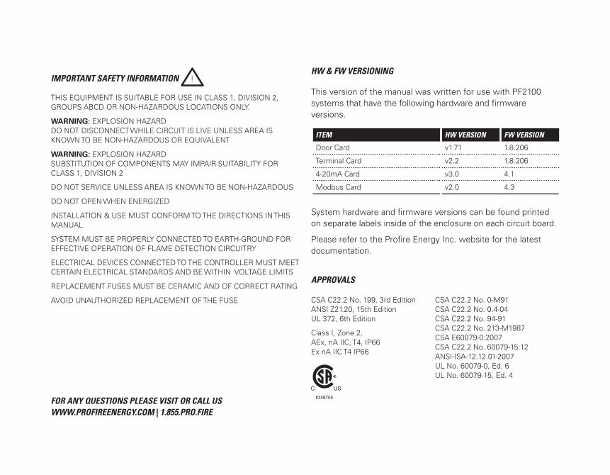
HW & FW VERSIONING
This version of the manual was written for use with PF2100 systems that have the following hardware and firmware versions.
ITEM HW VERSION FW VERSION
Door Card v1.71 1.8.206
Terminal Card v2.2 1.8.206
4-20mA Card v3.0 4.1
Modbus Card v2.0 4.3
System hardware and firmware versions can be found printed on separate labels inside of the enclosure on each circuit board.
Please refer to the Profire Energy Inc. website for the latest documentation.
APPROVALS
CSA C22.2 No. 199, 3rd Edition ANSI Z21.20, 15th Edition UL 372, 6th Edition
Class I, Zone 2, AEx, nA IIC, T4, IP66Ex nA IIC T4 IP66
CSA C22.2 No. 0-M91CSA C22.2 No. 0.4-04CSA C22.2 No. 94-91CSA C22.2 No. 213-M1987CSA E60079-0:2007CSA C22.2 No. 60079-15:12ANSI-ISA-12.12.01-2007UL No. 60079-0, Ed. 6 UL No. 60079-15, Ed. 4
#248705
1 Introduction ...........................................................................................................................................1
1.1 Included Components ..................................................................................................... 2
1.2 Technical Specifications................................................................................................... 3
1.3 System Diagram .............................................................................................................. 4
1.4 Terminal Card Descriptions ............................................................................................. 5
2 Installation .............................................................................................................................................8
2.1 Installation Warnings ...................................................................................................... 9
2.2 Mounting Instructions ................................................................................................... 10
2.3 Terminal Card Diagram .................................................................................................. 11
2.4 Wiring .............................................................................................................................. 12
3 User Interface & Settings .................................................................................................................19
3.1 User Interface ................................................................................................................. 19
3.2 Menu Navigation ........................................................................................................... 21
3.3 Menu Map ...................................................................................................................... 22
3.4 System Operation .......................................................................................................... 30
4 Troubleshooting ..................................................................................................................................34
4.1 Common Issues & Solutions ........................................................................................ 34
4.2 Shutdown Messages ..................................................................................................... 38
4.3 Alarm Codes ................................................................................................................... 44
4.4 Warning Messages ......................................................................................................... 46
4.5 Flame Detection Troubleshooting Guide ..................................................................... 47
4.6 Thermocouple Troubleshooting Guide ......................................................................... 51
5 Appendix A: PID Tuning ....................................................................................................................52
6 Appendix B: Field Calibration ..........................................................................................................53
7 Appendix C: Resetting to Defaults ..................................................................................................60
1 | Overview 1
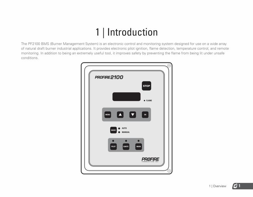
1 | IntroductionThe PF2100 BMS (Burner Management System) is an electronic control and monitoring system designed for use on a wide array of natural draft burner industrial applications. It provides electronic pilot ignition, flame detection, temperature control, and remote monitoring. In addition to being an extremely useful tool, it improves safety by preventing the flame from being lit under unsafe conditions.
FLAME
1 | Overview2
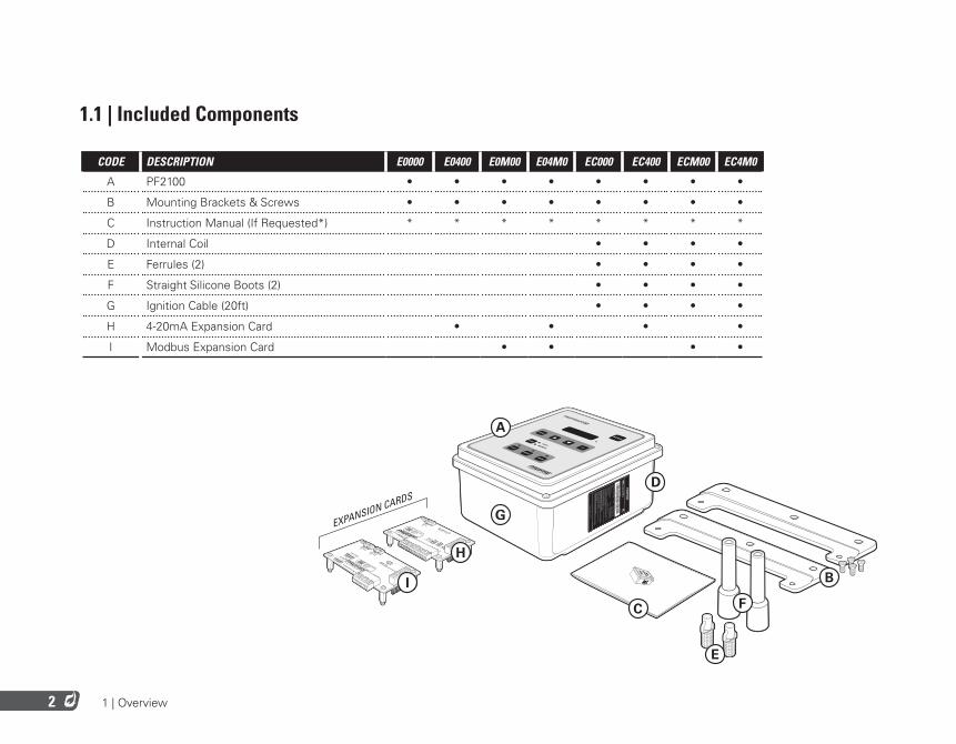
1.1 | Included Components
CODE DESCRIPTION E0000 E0400 E0M00 E04M0 EC000 EC400 ECM00 EC4M0
A PF2100 • • • • • • • •
B Mounting Brackets & Screws • • • • • • • •
C Instruction Manual (If Requested*) * * * * * * * *
D Internal Coil • • • •
E Ferrules (2) • • • •
F Straight Silicone Boots (2) • • • •
G Ignition Cable (20ft) • • • •
H 4-20mA Expansion Card • • • •
I Modbus Expansion Card • • • •
EXPANSION CARDS
F
A
E
I
G
B
D
H
C

1 | Overview 3
1.2 | Technical Specifications
TEMPERATURE RATINGS MIN MAX
Operating Range -40˚C (-40˚F) +55˚C (+130˚F)
Storage Range -40˚C (-40˚F) +80˚C (176˚F)
POWER CONSUMPTION 12V 24V
Controller only, display ON 2.6 W 2.9 W
Controller only, display OFF 1.1 W 1.2 W
Maximum Total Current Draw 5 A 5 A
Maximum Continuous Current* 4.5 V 4.5 V
Ignition Voltage (Internal Coil) Up to 20 kV Up to 40 kV
TERMINAL BLOCKS VALUE
Maximum Wire Gauge 12 AWG
STATUS CONTACT VALUE
Type Dry
MAX Voltage 40VDC
MAX Continuous Current 250mA
Impedance (When Closed) 15Ω
PHYSICAL DIMENSIONS VALUE
Width, Height, Depth 30.9 cm x 23.4 cm x 13.4 cm [12.15 in x9.23 in x5.28 in]
WEIGHT VALUE
E0000 Model 4.0lbs / 1.8kg
E0400 Model 4.5lbs / 2.0kg
E0M00 Model 4.5lbs / 2.0kg
EC000 Model 6.0lbs / 2.6kg
*All valves combined @100% duty cycle

1 | Overview4
1.3 | System Diagram
F2SPARE FUSE
Status+Status-Start+Start-ESD+ESD-
Proof of Closure+
Proof of Closure-HighPressure+HighPressure-
LowPressure+LowPressure-Level+Level-
HighTemp_TC+ (Yellow)
HighTemp_TC- (Red)
Process_TC+ (Yellow)
Process_TC- (Red)
AUX_TC+ (Yellow)
AUX_TC- (Red)
High Fire+ / Main+
4-20mA Out-
4-20mA Out+
Earth Ground
Common
12/24VDC
Coil-Coil+
Ion+Ion-
High Fire- / Main-
Low Fire+Low Fire-
Pilot+Pilot-
1 2 3
6 5 4
XXXXXX-XXXXX
XXX-2.3.0XXXXXX
SPARE FUSE
RESET
Ev1.8.005
4-20mA CARD
INTERNAL COIL
MODBUS CARD
RIBBON CABLE
FW VERSION LABEL
KEYPAD FLEX CABLE
HW SERIAL / VERSION LABEL
TERMINAL CARD
DOOR CARD
(OPTIONAL)
(OPTIONAL)
(OPTIONAL)
(DOOR TO TERMINAL)
DOOR & KEYPAD
SERIAL / MODEL LABEL
ENCLOSURE

2 | Installation 5
1.4 | Terminal Card Descriptions
This table provides connection details and a brief description of each terminal.
TERMINAL EXPECTED CONNECTIONS DESCRIPTION
12/24VDC Input power from a DC source Input power 10VDC - 28VDC, 5A MAX
Common Ground back to DC source Internally connected to EGND
EGND Earth Ground
4-20mA Out + Proportional Valve positive terminal or PLC 4-20mA positive input
This output can be used for either Proportional Valve Control or echoing the Process Temperature to a PLC.
A resistance of 120Ω to 250Ω is expected.4-20mA Out - Ground return for the 4-20mA output
HighTemp_TC + (YELLOW) High Temp Thermocouple positive lead “TYPE K” thermocouple must be connected between the “+” and “-” terminals and must not be electrically connected to ground.
An uninterrupted connection using “TYPE K” thermocouple wire is required for an accurate reading.
HighTemp_TC - (RED) High Temp Thermocouple negative lead
Process_TC + (YELLOW) Process Thermocouple positive lead
Process_TC - (RED) Process Thermocouple negative lead
AUX_TC + (YELLOW) Aux Thermocouple positive lead
AUX_TC - (RED) Aux Thermocouple negative lead
High Fire/Main + High Fire / Main Valve positive terminal Solenoid valves must be connected between the “+” and “-” terminals. The negative terminal is not directly connected to ground so a common return wire for the High Fire, Low Fire and Pilot valves cannot be used.
The total maximum continuous current for all valves is 4.5A.
[IHighFireValve + ILowFireValve + IPilotValve] < 4.5A
If the Valve PWM settings are set lower, the total peak load of all valves may be higher. For example, for 20% duty cycle, a total peak load of up to 9A may be possible.
High Fire/Main - High Fire / Main Valve negative terminal. Do not connect to ground.
Low Fire + Low Fire Valve positive terminal
Low Fire - Low Fire Valve negative terminal. Do not connect to ground.
Pilot + Pilot Valve positve terminal
Pilot - Pilot Valve negative terminal. Do not connect to ground.

2 | Installation6
TERMINAL EXPECTED CONNECTIONS DESCRIPTION
Ion + Flame Detection positive input. Connect to flame rod or external coil Ion terminal (depending on configuration)
A Kanthal rod should be placed directly in the pilot flame and connected to this input. The pilot assembly must be grounded for the flame detection to function properly. Input is protected from high voltage and can be connected in series with the high voltage terminals of an external ignition coil, allowing a single flame-rod to be used for both ignition and flame detection.
A 65VAC signal is applied to the flame rod. The source impedance is very high so there is no danger of sparking.
Ion - Flame Detection negative input. Connect to ground screw on pilot assembly or burner housing.
Ground return for flame detection.
Coil + Driver for the low voltage primary of the ignition coil.
The primary of the ignition coil should be connected to this terminal. The 12/24VDC input power will be applied for 1 ms and turned off for 50 ms while sparking.
This output is protected by a 250mA thermal fuse.Coil - Ground return for the ignition coil.
Status + Connect to PLC positive input contact or other alarm device.
The status “+” and “-” contacts will be closed when the system is running and opened when the system is shutdown. Dry contact output to indicate system status to an external device. ie. PLC. Note that the contacts are DC only and are not internally connected to power or ground.
40VDC, 250mA, 15Ω
Status - Connect to PLC negative input contact or other alarm device.

2 | Installation 7
TERMINAL EXPECTED CONNECTIONS DESCRIPTION
Start + Remote start input from an external device. ie. PLC.
Dry contact switch is expected. The input is internally pulled up to 9VDC via a 3.75kΩ resistance. Jumper “+” and “-” if not used.
All input contacts can use a single common ground return if desired.Start - Ground
ESD + External Shutdown input, typically plant ESD loop.
ESD - Ground
Proof of Closure + Proof of Closure from main valve(s).
Proof of Closure - Ground
High Pressure + Input from a mechanical High Pressure switch.
High Pressure - Ground
Low Pressure + Input from a mechanical Low Pressure switch.
Low Pressure - Ground
Level + Input from a float-switch mounted in the bath.
Dry contact switch is expected. The input is internally pulled up to 9VDC via a 3.75kΩ resistance. Jumper “+” and “-” if not used.
All input contacts can use a single common ground return if desired.Level - Ground
2 | Installation8
2 | InstallationThe PF2100 can be used with many different systems. Before you begin installation, identify which system the BMS will be used to control. In addition to this document, Profire has several Quick Start Guides available describing common installation scenarios. These can be found at www.profireenergy.com.
The steps provided here are general and can help you to identify questions that need to be answered to complete the installation process. If you are new to the PF2100, you should read this whole section and follow the instructions closely.
STEPS
1. Review all installation warnings
2. Install the system
3. Connect the required wiring including Power, Valves, Thermocouples, and Ignition Coil / Flame Detection wiring
4. Connect any additional wiring as required for your specific application. Commonly used lines include the Status Contact, Dry Contact Inputs, 4-20mA Temperature Output, and Expansion Cards
To know which options are required, you should consult the engineer or technician who designed the site. You should also be familiar with the local electrical and gas code for the site.
2 | Installation 9
2.1 | Installation Warnings !
Before installing the PF2100, please review the following list of warnings. Failure to consider these warnings may result in death, electrocution, property damage, product damage, and/or government fines.
1. The PF2100 is not intended for use on burners greater than 12.5 MMBtuh. It is against code in many locations.
2. To use the PF2100 on burners greater than 5 MMBtuh, it is recommended that the low fire feature with two safety shutoff valves be used. At least one of these valves should use Proof of Closure. This is required in many locations.
3. Failure to properly ground the pilot assembly back to the PF2100’s Ion terminal may result in accidental electrocution, product damage, or simply failure to ignite the pilot.
4. The PF2100 generates 20kV - 40kV at its high voltage output terminal which can cause cardiac arrest. Do not touch or place any object near the ignition coil’s high voltage terminal or connected ignition wire while the product is operating. Even without making physical contact with the terminal, it is possible to draw a spark from several inches away, especially if the pilot bracket is not properly grounded.
5. Never leave the PF2100 running unattended without the door screws securely tightened down. This is to prevent moisture from getting inside of the enclosure and damaging the product. Moisture damage to the internal
circuitry is not covered by the product warranty if the door has been left open.
6. All conduit ports drilled into the PF2100 enclosure must be CSA/NEMA Type 4 rated and be sealed in order to maintain the Type 4 rating.
2 | Installation10
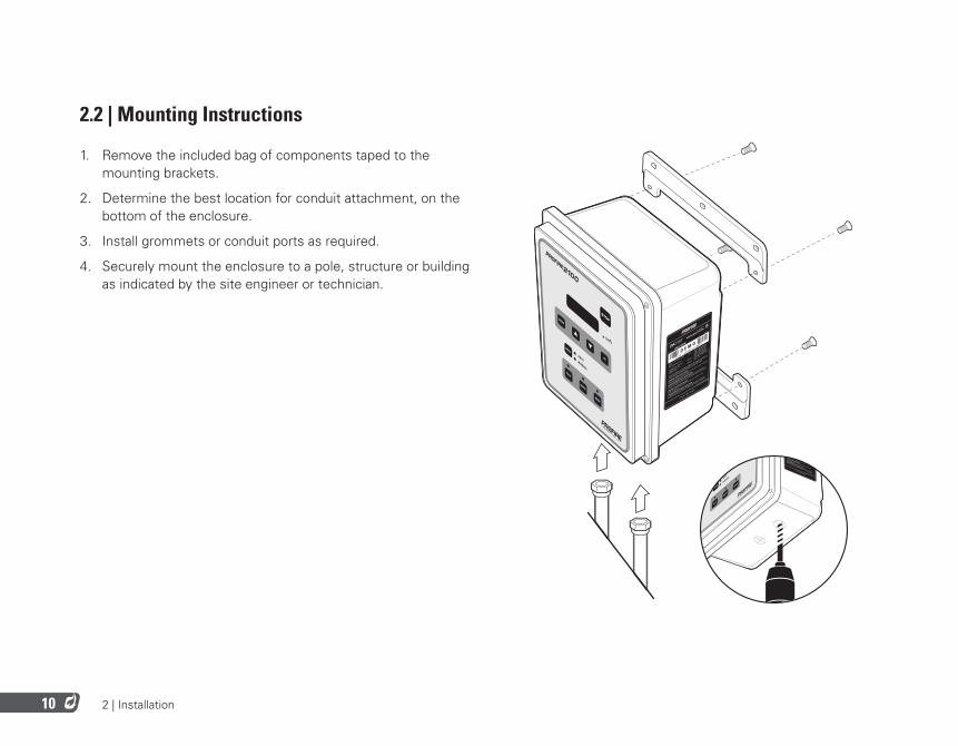
2.2 | Mounting Instructions
1. Remove the included bag of components taped to the mounting brackets.
2. Determine the best location for conduit attachment, on the bottom of the enclosure.
3. Install grommets or conduit ports as required.
4. Securely mount the enclosure to a pole, structure or building as indicated by the site engineer or technician.
1 8 5 5 P R O F I R E
N HAZARD
ECT WHILE CIRCUIT IS LIVE UNLESS AREA IS KNOWN
HAZARDOUS OR EQUIVALENT
RTISSEMENT: RISQUE D’EXPLOSION
NE PAS DEBRANCHER TANT QUE LE CIRCUIT EST SOUS TENSION, A
MOUNS QU’IL NE S’AGISSE D’UN EMPLACEMENT NON DANGEREAUX
WARNING: EXPLOSION HAZARD
SUBSTITUTION OF COMPONENTS MAY IMPAIR SUITABILITY FOR
CLASS I, DIVISION 2.
AVERTISSEMENT: RISQUE D’EXPLOSION
LA SUBSTITUTION DE COMPOSANTS PEUT RENDURE CE MATERIEL
INACCEPTABLE POUR LES EMPLACEMENTS DE CLASSE I, DIVISION 2
UCTIVEE IN CLASS I, DIVISION 2,
DOUS LOCATIONS ONLY.
1101-009-E0000 Rev 3.0
FLAME
MC#248705
1 8 5 5 P R O F I R E
WARNING: E
XPLOSION HAZARD
DO NOT DISCONNECT WHILE CIRCUIT IS
LIVE UNLESS AREA IS KNOWN
TO BE NON-HAZARDOUS OR EQUIVALENT
AVERTISSEMENT: RISQUE D
’EXPLOSION
NE PAS DEBRANCHER TANT QUE LE CIRCUIT EST SOUS TENSION, A
MOUNS QU’IL NE S’AGISSE D’UN EMPLACEMENT NON DANGEREAUX
WARNING: E
XPLOSION HAZARD
SUBSTITUTION OF COMPONENTS MAY IM
PAIR SUITABILITY FOR
CLASS I, DIVISION 2.
AVERTISSEMENT: RISQUE D
’EXPLOSION
LA SUBSTITUTION DE COMPOSANTS PEUT RENDURE CE MATERIEL
INACCEPTABLE POUR LES EMPLACEMENTS DE CLASSE I, DIVISION 2
CSA 22.2 No. 199-2007
ANSI Z21.2
0-2007
UL1998-2004
Class 1, Div 2, G
rp ABCD
IP54
T4A, NEMA Type 4X
INPUT: 12VDC, 2.6W Display ON
12VDC, 1.1W Display OFF
24VDC, 2.9W Display ON
24VDC, 1.2W Display OFF
OUTPUT: 12VDC, 5A max IN
DUCTIVE
24VDC, 5A max INDUCTIVE
AMBIENT: -40˚C - +
55˚C
THIS EQUIPMENT IS SUITABLE FOR USE IN CLASS I, D
IVISION 2,
GROUPS ABCD OR NON-HAZARDOUS LOCATIONS ONLY.
1101-009-E0000 Rev 3.0
SERIAL NO.
MODEL NO. 1PS
21-E00
00
D E MO
BURNER
MANAGEMENT SYSTEM
2100
2 | Installation 11
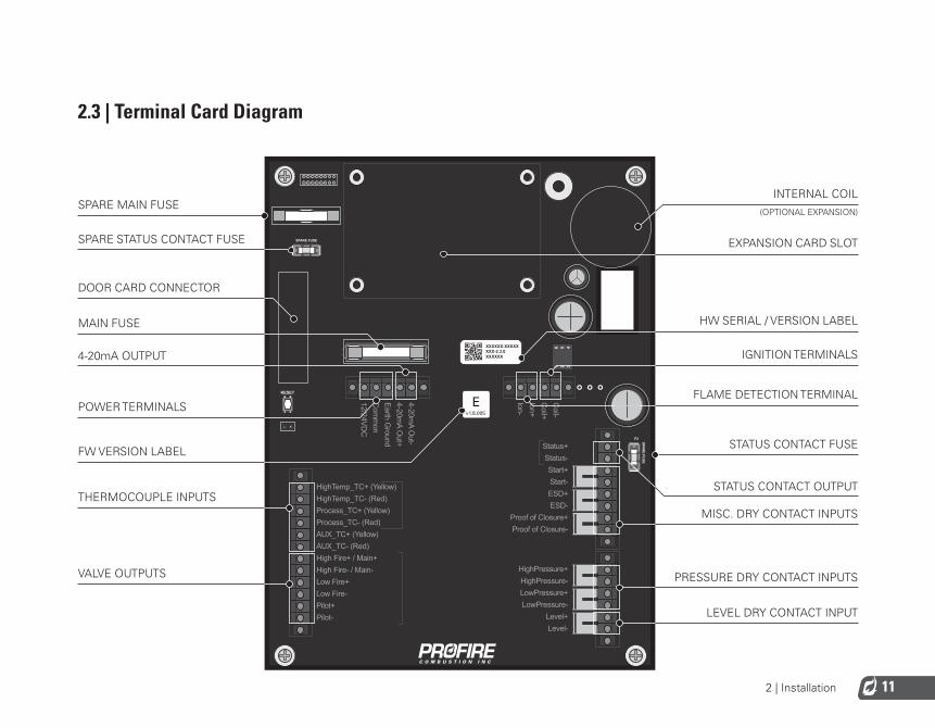
2.3 | Terminal Card Diagram
F2 SPAR
E FUSE
Status+Status-Start+Start-ESD+ESD-
Proof of Closure+Proof of Closure-
HighPressure+HighPressure-LowPressure+LowPressure-
Level+Level-
HighTemp_TC+ (Yellow)HighTemp_TC- (Red)Process_TC+ (Yellow)Process_TC- (Red)AUX_TC+ (Yellow)AUX_TC- (Red)High Fire+ / Main+
4-20mA O
ut-4-20m
A Out+
Earth Ground
Com
mon
12/24VDC
Coil-
Coil+
Ion+Ion-
High Fire- / Main-Low Fire+Low Fire-Pilot+Pilot-
1 2 3
6 5 4XXXXXX-XXXXXXXX-2.3.0XXXXXX
SPARE FUSE
RESET
Ev1.8.005
INTERNAL COIL
IGNITION TERMINALS
STATUS CONTACT OUTPUT
HW SERIAL / VERSION LABEL
EXPANSION CARD SLOT
FLAME DETECTION TERMINAL
STATUS CONTACT FUSE
LEVEL DRY CONTACT INPUT
PRESSURE DRY CONTACT INPUTS
MISC. DRY CONTACT INPUTS
4-20mA OUTPUT
FW VERSION LABEL
VALVE OUTPUTS
THERMOCOUPLE INPUTS
MAIN FUSE
SPARE MAIN FUSE
SPARE STATUS CONTACT FUSE
DOOR CARD CONNECTOR
POWER TERMINALS
(OPTIONAL EXPANSION)
2 | Installation12
2.4 | Wiring
The wiring in this section is required for all PF2100 installations. Skipping or performing any steps in this section incorrectly will result in the PF2100 not functioning properly.
POWER
The PF2100 can be powered from 12VDC or 24VDC. The maximum current that the PF2100 can safely handle without blowing the main fuse is 5A. The system on its own draws about 100mA. The rest of the current is used by additional hardware such as valves. Make sure that you select a power supply that is rated appropriately for the total amount of current that will be consumed by all devices attached to it.
WIRING STEPS
1. Wire the Common terminal to the negative terminal of the power supply.
2. Wire the Earth Ground terminal to the shield of all conduit ports installed in the enclosure.
3. Connect the Earth Ground terminal to an actual earth ground connection.
4. Wire the 12/24VDC terminal to the positive terminal of the power supply.
VALVES
There are four valve control outputs on the PF2100: Pilot, Low Fire, 4-20mA Output, and High Fire/Main.
WIRING STEPS
1. Wire the Pilot valve to the Pilot +/- terminals.
2. Wire the Main valve to the High Fire / Main +/- terminals.
3. If Low Fire is required in your application, do one of the following:
• Wire the Low Fire valve to the Low Fire +/- terminals• If you want to use a proportional valve, wire the valve to the 4-20mA Out +/- terminals

2 | Installation 13
4. Make sure that each valve has a separate return wire. Multiple valves sharing common return wires will not function properly.
5. Connect valve EGND wires to Earth Ground.
NOTES
It is possible to connect multiple valves to the same control output. If you do this, make sure that the configuration you are using meets local codes and also does not exceed the total current rating of the PF2100.
The negative valve control wires are NOT connected directly to ground. This means you cannot use a common return wire for all valves.
THERMOCOUPLES
The High Temp and Process thermocouple inputs are mandatory and must be connected to a Dual Element thermocouple. The Auxiliary thermocouple is only needed when a second process temperature (such as the outlet temperature on a line heater) must be monitored. Otherwise, the Auxiliary thermocouple terminals can be left unconnected. Please note that Type-k thermocouple wire and connectors should be used exclusively.
WIRING STEPS
1. Connect a Dual Element, Type-k thermocouple to the Process and High Temp thermocouple inputs.
2. If needed, connect a single Type-k thermocouple to the AUX thermocouple input.
3. Make sure that all connections are made using Type-k thermocouple wire and connectors.
NOTE | all thermocouples must be:
• Isolated from ground• Isolated from power• Type-k thermocouples• Connected with 20 AWG or larger Type-k extension wire• Placed a safe distance from high voltage lines and shielded when necessary.
2 | Installation14
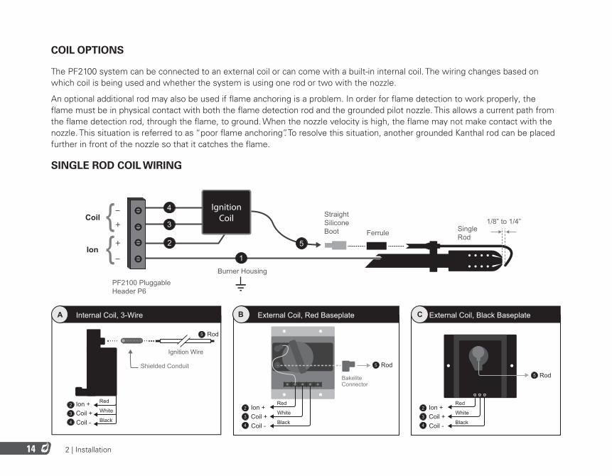
COIL OPTIONS
The PF2100 system can be connected to an external coil or can come with a built-in internal coil. The wiring changes based on which coil is being used and whether the system is using one rod or two with the nozzle.
An optional additional rod may also be used if flame anchoring is a problem. In order for flame detection to work properly, the flame must be in physical contact with both the flame detection rod and the grounded pilot nozzle. This allows a current path from the flame detection rod, through the flame, to ground. When the nozzle velocity is high, the flame may not make contact with the nozzle. This situation is referred to as “poor flame anchoring”. To resolve this situation, another grounded Kanthal rod can be placed further in front of the nozzle so that it catches the flame.
SINGLE ROD COIL WIRING
+
+
IgnitionCoil Straight
SiliconeBoot
PF2100 PluggableHeader P6
Burner Housing
Ferrule SingleRod
4
3
2
1
{{ 5
Coil
Ion
1/8” to 1/4”
Red
White
Black
Internal Coil, 3-WireA
Rod
Shielded Conduit
5
Ignition Wire
Ion +Coil +Coil -
2
3
4
External Coil, Red BaseplateB
Ion +
BakeliteConnector
Coil +Coil -
2
3
4
Rod5
Red
White
Black
Ion +
Rod
Coil +Coil -
2
5
3
4
External Coil, Black BaseplateC
Red
White
Black

2 | Installation 15
WIRING STEPS
1. Connect the PF2100’s Ion- terminal to the Burner Housing. Using a multimeter, verify that the Burner Housing and the Pilot Nozzle are both strongly connected to earth ground. If not, you may need to run an additional wire between the Burner Housing and the Pilot Assembly ground screw. In general, you should use 7mm Ignition Wire but 16 AWG may be acceptable for runs less than 8m (25 feet) total. Do not exceed 15m (50 feet) total. Avoid running this wire through metal conduit if possible as this will limit the length of wire that will work.
2. Connect the PF2100’s Ion+ terminal to the Ignition Coil. Use 16 AWG if extra wire is needed.
3. Connect the PF2100’s Coil+ terminal to the Ignition Coil. Use 16 AWG if extra wire is needed.
4. Connect the PF2100’s Coil- terminal to the Ignition Coil. Use 16 AWG if extra wire is needed.
5. Connect the Kanthal Rod to the Ignition Coil. Use the included Ferrule and Straight Silicone Boot to ensure that the connection is robust. Always use 7mm Ignition Wire and do not exceed 5m (15 feet). Avoid running this wire through metal conduit if possible as this will limit the length of wire that will work.
• For Coils A and C: Strip ¼” from the ignition wire, insert into the high voltage terminal on the coil, tighten set screw on the top of the coil, and replace the rubber cap over the set screw.
• For Coil B: Strip ¼” from the ignition wire, insert into the 90 degree bakelite connector, tighten the screw in the bakelite connector, and click the connector onto the high voltage terminal post on the coil.
6. Adjust the Rod positioning (bend it if necessary) so that there is a 1/8 to 1/4” gap between the rod and the front of the pilot nozzle.
2 | Installation16
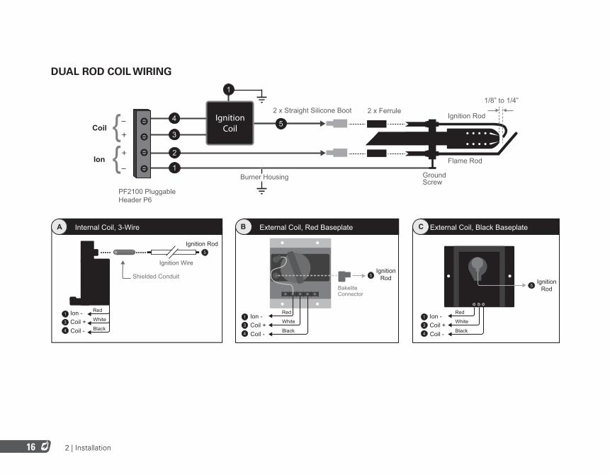
DUAL ROD COIL WIRING
Red
White
Black
Internal Coil, 3-WireA
Ignition Rod
Shielded Conduit
5
Ignition Wire
Ion -Coil +Coil -
1
3
4
External Coil, Red BaseplateB
Ion -
BakeliteConnector
Coil +Coil -
1
3
4
IgnitionRod5
Red
White
Black
Ion -
IgnitionRod
Coil +Coil -
1
5
3
4
External Coil, Black BaseplateC
Red
White
Black
+
+
IgnitionCoil
2 x Straight Silicone Boot
PF2100 PluggableHeader P6
2 x Ferrule
Burner Housing
Ignition Rod
Flame Rod
GroundScrew
4
3
2
1
{{
5Coil
Ion1
1/8” to 1/4”
2 | Installation 17
WIRING STEPS
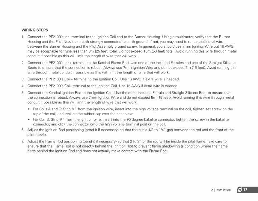
1. Connect the PF2100’s Ion- terminal to the Ignition Coil and to the Burner Housing. Using a multimeter, verify that the Burner Housing and the Pilot Nozzle are both strongly connected to earth ground. If not, you may need to run an additional wire between the Burner Housing and the Pilot Assembly ground screw. In general, you should use 7mm Ignition Wire but 16 AWG may be acceptable for runs less than 8m (25 feet) total. Do not exceed 15m (50 feet) total. Avoid running this wire through metal conduit if possible as this will limit the length of wire that will work.
2. Connect the PF2100’s Ion+ terminal to the Kanthal Flame Rod. Use one of the included Ferrules and one of the Straight Silicone Boots to ensure that the connection is robust. Always use 7mm Ignition Wire and do not exceed 5m (15 feet). Avoid running this wire through metal conduit if possible as this will limit the length of wire that will work.
3. Connect the PF2100’s Coil+ terminal to the Ignition Coil. Use 16 AWG if extra wire is needed.
4. Connect the PF2100’s Coil- terminal to the Ignition Coil. Use 16 AWG if extra wire is needed.
5. Connect the Kanthal Ignition Rod to the Ignition Coil. Use the other included Ferrule and Straight Silicone Boot to ensure that the connection is robust. Always use 7mm Ignition Wire and do not exceed 5m (15 feet). Avoid running this wire through metal conduit if possible as this will limit the length of wire that will work.
• For Coils A and C: Strip ¼” from the ignition wire, insert into the high voltage terminal on the coil, tighten set screw on the top of the coil, and replace the rubber cap over the set screw.
• For Coil B: Strip ¼” from the ignition wire, insert into the 90 degree bakelite connector, tighten the screw in the bakelite connector, and click the connector onto the high voltage terminal post on the coil.
6. Adjust the Ignition Rod positioning (bend it if necessary) so that there is a 1/8 to 1/4” gap between the rod and the front of the pilot nozzle.
7. Adjust the Flame Rod positioning (bend it if necessary) so that 2 to 3” of the rod will be inside the pilot flame. Take care to ensure that the Flame Rod is not directly behind the Ignition Rod to prevent flame shadowing (a condition where the flame parts behind the Ignition Rod and does not actually make contact with the Flame Rod).
2 | Installation18
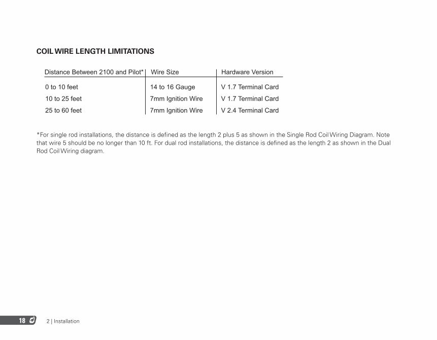
COIL WIRE LENGTH LIMITATIONS
Distance Between 2100 and Pilot*
0 to 10 feet
10 to 25 feet
25 to 60 feet
Wire Size Hardware Version
14 to 16 Gauge
7mm Ignition Wire
7mm Ignition Wire
V 1.7 Terminal Card
V 1.7 Terminal Card
V 2.4 Terminal Card
* For single rod installations, the distance is defined as the length 2 plus 5 as shown below. For dual rod installations, the distance is defined as the length 2 as shown below.
*For single rod installations, the distance is defined as the length 2 plus 5 as shown in the Single Rod Coil Wiring Diagram. Note that wire 5 should be no longer than 10 ft. For dual rod installations, the distance is defined as the length 2 as shown in the Dual Rod Coil Wiring diagram.
3 | User Interface & Settings 19
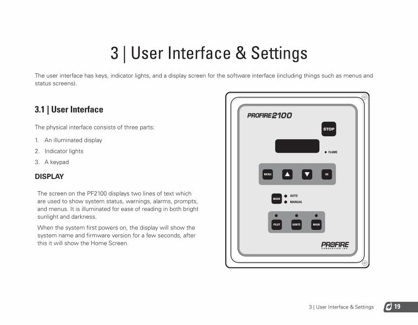
3 | User Interface & SettingsThe user interface has keys, indicator lights, and a display screen for the software interface (including things such as menus and status screens).
3.1 | User Interface
The physical interface consists of three parts:
1. An illuminated display
2. Indicator lights
3. A keypad
DISPLAY
The screen on the PF2100 displays two lines of text which are used to show system status, warnings, alarms, prompts, and menus. It is illuminated for ease of reading in both bright sunlight and darkness.
When the system first powers on, the display will show the system name and firmware version for a few seconds, after this it will show the Home Screen.
FLAME

3 | User Interface & Settings20
INDICATOR LIGHTS
FLAME LIGHTIndicates that the system is detecting the pilot flame.
AUTO LIGHTIndicates that the system is running in Auto Mode.
MANUAL LIGHTIndicates that the system is running in Manual mode.
PILOT LIGHTIndicates that the pilot valve is open.
IGNITE LIGHTIndicates that the system is sparking to ignite the pilot.
MAIN LIGHTIndicates that the main valve is open.
KEYS
STOP KEYUsed to stop the system immediately. (Turns off the burner.)
MENU KEYUsed to navigate through the menu.
UP KEYUsed to adjust a setting upwards and to scroll up through lists.
DOWN KEYUsed to adjust a setting downwards and to scroll down through lists.
OK KEYUsed to enter a menu, acknowledge a prompt, save an edited setting, or return to the home screen.
MODE KEYUsed to toggle between Manual and Auto Modes of operation.
PILOT KEYUsed in Manual Mode to test the pilot valve.
IGNITE KEYUsed in Manual Mode to test the ignition circuit.
MAIN KEYUsed in Manual Mode to test the main valve.
3 | User Interface & Settings 21
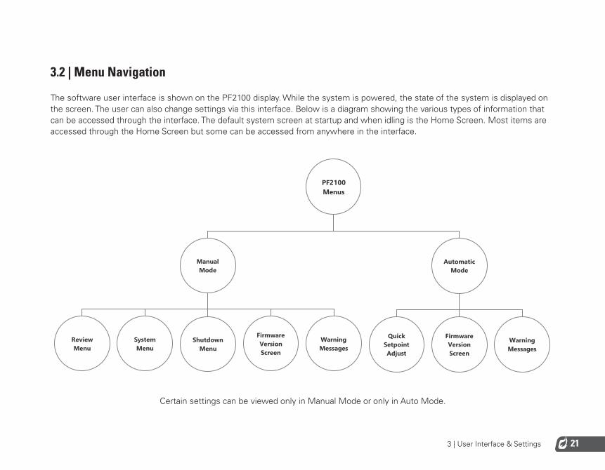
3.2 | Menu Navigation
The software user interface is shown on the PF2100 display. While the system is powered, the state of the system is displayed on the screen. The user can also change settings via this interface. Below is a diagram showing the various types of information that can be accessed through the interface. The default system screen at startup and when idling is the Home Screen. Most items are accessed through the Home Screen but some can be accessed from anywhere in the interface.
PF2100Menus
WarningMessages
FirmwareVersionScreen
QuickSetpointAdjust
AutomaticMode
WarningMessages
FirmwareVersionScreen
ShutdownMenu
SystemMenu
ReviewMenu
ManualMode
Certain settings can be viewed only in Manual Mode or only in Auto Mode.
3 | User Interface & Settings22
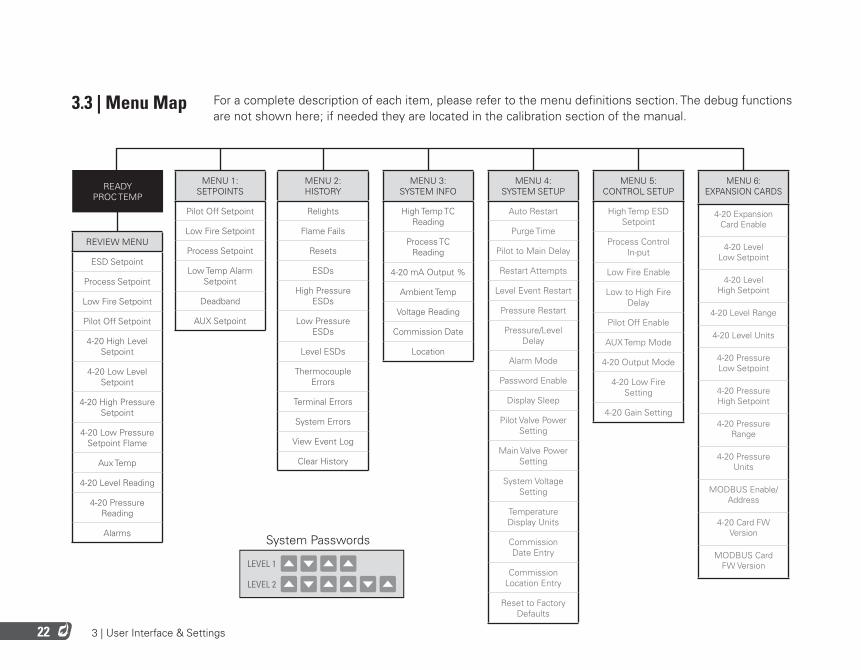
3.3 | Menu Map For a complete description of each item, please refer to the menu definitions section. The debug functions are not shown here; if needed they are located in the calibration section of the manual.
REVIEW MENU
ESD Setpoint
Process Setpoint
Low Fire Setpoint
Pilot Off Setpoint
4-20 High Level Setpoint
4-20 Low Level Setpoint
4-20 High Pressure Setpoint
4-20 Low Pressure Setpoint Flame
Aux Temp
4-20 Level Reading
4-20 Pressure Reading
Alarms
READY PROC TEMP
MENU 1: SETPOINTS
Pilot Off Setpoint
Low Fire Setpoint
Process Setpoint
Low Temp Alarm Setpoint
Deadband
AUX Setpoint
MENU 2: HISTORY
Relights
Flame Fails
Resets
ESDs
High Pressure ESDs
Low Pressure ESDs
Level ESDs
Thermocouple Errors
Terminal Errors
System Errors
View Event Log
Clear History
MENU 4: SYSTEM SETUP
Auto Restart
Purge Time
Pilot to Main Delay
Restart Attempts
Level Event Restart
Pressure Restart
Pressure/Level Delay
Alarm Mode
Password Enable
Display Sleep
Pilot Valve Power Setting
Main Valve Power Setting
System Voltage Setting
Temperature Display Units
Commission Date Entry
Commission Location Entry
Reset to Factory Defaults
MENU 5: CONTROL SETUP
High Temp ESD Setpoint
Process Control In-put
Low Fire Enable
Low to High Fire Delay
Pilot Off Enable
AUX Temp Mode
4-20 Output Mode
4-20 Low Fire Setting
4-20 Gain Setting
MENU 6: EXPANSION CARDS
4-20 Expansion Card Enable
4-20 Level Low Setpoint
4-20 Level High Setpoint
4-20 Level Range
4-20 Level Units
4-20 Pressure Low Setpoint
4-20 Pressure High Setpoint
4-20 Pressure Range
4-20 Pressure Units
MODBUS Enable/Address
4-20 Card FW Version
MODBUS Card FW Version
MENU 3: SYSTEM INFO
High Temp TC Reading
Process TC Reading
4-20 mA Output %
Ambient Temp
Voltage Reading
Commission Date
Location
LEVEL 1
LEVEL 2
System Passwords
3 | User Interface & Settings 23
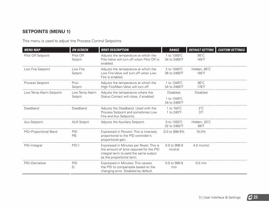
SETPOINTS (MENU 1)
This menu is used to adjust the Process Control Setpoints.
MENU MAP ON SCREEN BRIEF DESCRIPTION RANGE DEFAULT SETTING CUSTOM SETTINGS
Pilot Off Setpoint Pilot Off Setpnt
Adjusts the temperature at which the Pilot Valve will turn off when Pilot Off is enabled.
1 to 1349˚C 34 to 2460˚F
85˚C 185˚F
Low Fire Setpoint Low Fire Setpnt
Adjusts the temperature at which the Low Fire Valve will turn off when Low Fire is enabled.
2 to 1349˚C 36 to 2460˚F
Hidden, 85˚C 185˚F
Process Setpoint Proc Setpnt
Adjusts the temperature at which the High Fire/Main Valve will turn off
1 to 1349˚C 34 to 2460˚F
80˚C 176˚F
Low Temp Alarm Setpoint Low Temp Alarm Setpnt
Adjusts the temperature where the Status Contact will close, if enabled.
Disabled,
1 to 1349˚C 34 to 2460˚F
Disabled
Deadband Deadband Adjusts the Deadband. Used with the Process Setpoint and sometimes Low Fire and Aux Setpoints.
1 to 150˚C 1 to 240˚F
2˚C 3˚F
Aux Setpoint AUX Setpnt Adjusts the Auxiliary Setpoint. 0 to 1350˚C 32 to 2462˚F
Hidden, 20˚C 68˚F
PID–Proportional Band PID PB:
Expressed in Percent. This is inversely proportional to the PID controller’s proportional gain.
0.0 to 999.9% 10.0%
PID–Integral PID I: Expressed in Minutes per Reset. This is the amount of time required for the PID integral term to yield the same output as the proportional term.
0.0 to 999.9 min/rst
4.0 min/rst
PID–Derivative PID D:
Expressed in Minutes. This causes the PID to compensate based on the changing error. Disabled by default.
0.0 to 999.9 min
0.0 min
3 | User Interface & Settings24
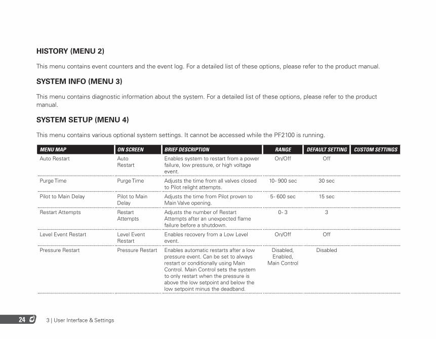
HISTORY (MENU 2)
This menu contains event counters and the event log. For a detailed list of these options, please refer to the product manual.
SYSTEM INFO (MENU 3)
This menu contains diagnostic information about the system. For a detailed list of these options, please refer to the product manual.
SYSTEM SETUP (MENU 4)
This menu contains various optional system settings. It cannot be accessed while the PF2100 is running.
MENU MAP ON SCREEN BRIEF DESCRIPTION RANGE DEFAULT SETTING CUSTOM SETTINGS
Auto Restart Auto Restart
Enables system to restart from a power failure, low pressure, or high voltage event.
On/Off Off
Purge Time Purge Time Adjusts the time from all valves closed to Pilot relight attempts.
10 - 900 sec 30 sec
Pilot to Main Delay Pilot to Main Delay
Adjusts the time from Pilot proven to Main Valve opening.
5 - 600 sec 15 sec
Restart Attempts Restart Attempts
Adjusts the number of Restart Attempts after an unexpected flame failure before a shutdown.
0 - 3 3
Level Event Restart Level Event Restart
Enables recovery from a Low Level event.
On/Off Off
Pressure Restart Pressure Restart Enables automatic restarts after a low pressure event. Can be set to always restart or conditionally using Main Control. Main Control sets the system to only restart when the pressure is above the low setpoint and below the low setpoint minus the deadband.
Disabled, Enabled,
Main Control
Disabled

3 | User Interface & Settings 25
MENU MAP ON SCREEN BRIEF DESCRIPTION RANGE DEFAULT SETTING CUSTOM SETTINGS
Pressure/Level Delay PRS/LVL Delay
Pressure and Level shutdown delay. On/Off Off
Alarm Mode Alarm Mode Adjusts the behaviour of Status Contact relative to Start Contact.
Alm when Off, No Alm When
Off
No Alm when Off
Password Enable Password Enable Password Protection (Menu 1-3) On/Off Off
Display Sleep Display Sleep Enable Sleep Mode for the Display Never, After 10 Min
Never
Pilot Valve Power Setting Pilot Solenoid PWM
Adjusts the Pilot Valve PWM duty cycle. Off, 80%, 60%, 40%,
20%
60%
Main Valve Power Setting Main Solenoid PWM
Adjusts the Main Valve PWM duty cycle.
Off, 80%, 60%, 40%,
20%
60%
System Voltage Setting System Voltage
Configures the expected input voltage for the system.
12V, 24V 12V
Temperature Display Units Temp Units Configures the temperature units displayed by the system.
Fahrenheit, Celsius
Celsius
Commission Date Entry Commission Date Set the date that the system was commissioned.
DD-MMM-YYYY
01-JUN-2012
Commission Location Entry Commission Loc Set the install location of the system. 14 Characters Max.
A-Z, 0-9, -./
Reset to Factory Defaults Restore Factory Defaults
Restore all settings to the factory default.
Yes/No No

3 | User Interface & Settings26
CONTROL SETUP (MENU 5)
This menu contains various optional Process Control settings. It cannot be accessed while the PF2100 is running.
MENU MAP ON SCREEN BRIEF DESCRIPTION RANGE DEFAULT SETTING CUSTOM SETTINGS
High Temp ESD Setpoint High Temp ESD Setpoint
Adjusts the High Temperature shutdown setpoint.
2 to 1350˚C 36 to 2462˚F
90˚C 194˚F
Process Control Input Process Control Configure the thermocouple used as the Process Temperature.
Process TC, AUX TC
Process TC
Low Fire Enable Low Fire Enables Low Fire feature and setpoint. Disabled, on at Proc Setpnt, on at Low Fire
Setpnt
Disabled
Low to High Fire Delay Low to High Fire Delay
Adjusts the time from Low Fire Valve opening to High Fire Valve opening, when Low Fire is enabled.
30 - 600 sec Hidden, 30 sec
Pilot Off Enable Pilot Off Enables Pilot Off feature and setpoint. Disabled, Enabled
Enabled
Aux Temp Mode AUX Temp Mode Configures how the Auxiliary Thermocouple is used.
Disabled, Display Only, Temp Main
Ctl, Temp ESD
Disabled
4-20 Output Mode 4-20 Out Mode Configures 4-20 Output mode. Valve Control 1 Valve Control 2, Temp Output
Valve Control 1
4-20 Low Fire Setting 4-20 Out Lo Fire Setting
Sets the minimum output for the 4-20mA Output when used for Valve Control.
0 to 70% 40%
4-20 Gain Setting 4-20 Out Cntrl Gain
Sets the adjustment speed of the control loop for the 4-20mA Output when used for Valve Control.
0.1 to 1%/s 0.5%/s

3 | User Interface & Settings 27
EXPANSION CARDS (MENU 6)
This menu contains settings relating to expansion cards.
MENU MAP ON SCREEN BRIEF DESCRIPTION RANGE DEFAULT SETTING CUSTOM SETTINGS
4-20 Input Card Enable 4-20 Input Card Enabled
Enable the 4-20mA Expansion Card and setpoints.
No/Yes No
4-20 Level Units 4-20 LVL Units
Adjusts the display units for the 4-20mA Level Input.
%, m3, BBL, GAL,L
Hidden, m3
4-20 Level Range 4-20 LVL Range Adjusts Max Level of the tank. 0-10000 Hidden, 120m3
4-20 Level Zero Offset 4-20 LVL Zero Offset
Adjusts the level reading corresponding to a 4mA input.
0 to Low Setpoint
0
4-20 Level Low Setpoint 4-20 LVL Low Setpnt
Adjusts 4-20 Low Level trip point. 0-Max Volume
Hidden, 60m3
4-20 Level High Setpoint 4-20 LVL High Setpnt
Adjusts 4-20 High Level trip point. 0-Max Volume
Hidden, 117m3
4-20 Pressure Units 4-20 PRS Units
Adjusts the display units for the 4-20mA Pressure Input.
PSI, kPa, inWC, cmWC,
ksc
Hidden, PSI
4-20 Pressure Range 4-20 PRS Range Adjusts Max pressure of the fuel train. 0-2000 Hidden, 30.0 PSI
4-20 Pressure Low Setpoint 4-20 PRS Low Setpnt
Adjusts 4-20 Low Pressure trip point. 0-High Setpoint
Hidden, 3.0 PSI
4-20 Pressure High Setpoint 4-20 PRS High Setpnt
Adjusts 4-20 High Pressure trip point. Low setpoint -Max Pressure
Hidden, 25.0 PSI
MODBUS Enable/Address Modbus Card Enable control and address for the Modbus Expansion Card.
Disabled, 1-128
Disabled
4-20 Card FW Version 4-20 FW Display Expansion Card FW version. N/A N/A
MODBUS Card FW Version MBUS FW Display Expansion Card FW version. N/A N/A

3 | User Interface & Settings28
REVIEW MENU
This menu allows various commonly needed system settings and status parameters to be reviewed while the system is running.
MENU MAP ON SCREEN BRIEF DESCRIPTION RANGE DEFAULT SETTING CUSTOM SETTINGS
ESD Setpoint ESD Setpnt Temp at which system will shutdown.
Process Setpoint ProcSetpnt Temp at which High Fire / Main Valve will turn off.
Low Fire Setpoint LF Setpnt Temp at which Low Fire Valve will turn off if Low Fire is enabled.
Pilot Off Setpoint Pilot off Temp at which Pilot Valve will turn off if Pilot is enabled.
4-20 High Level Setpoint HLV Level at which 4-20mA Output contacts will toggle.
4-20 Low Level Setpoint LLV Level below which the system will shutdown or wait if Level Event Restart is enabled.
4-20 High Pressure Setpoint HPR Pressure above which the system will shutdown after Main.
4-20 Low Pressure Setpoint LPR Pressure below which the system will shutdown or wait if Auto Restart is enabled.
Flame Flame Current Flame Quality.
Aux Temp AUX Temp Current Aux Temp reading.
4-20 Level Reading LVL Current 4-20mA Level input reading.
4-20 Pressure Reading PRS Current 4-20mA Pressure input reading.

3 | User Interface & Settings 29
MENU MAP ON SCREEN BRIEF DESCRIPTION RANGE DEFAULT SETTING CUSTOM SETTINGS
TC Debug Screen DH=ww TH=xx TP=yy TA=zz
Shows the current readings of all temperature sensors simultaneously always in degrees celsius regardless of the display unit setting. DH=Door Card High Temp Thermocouple TH=Terminal Card, High Temp Thermocouple TP=Terminal Card Process Thermocouple TA=Terminal Card Ambient Thermocouple
Alarms Alarms Lists up to 3 simultaneous alarm codes if any are present.

3 | User Interface & Settings30
3.4 | System Operation
This section includes information about how to start and stop the system, how to review key system settings, how to adjust setpoints while the system is running, and how to check the system firmware versions.
STARTING THE SYSTEM
There are five different ways to start the system:
AUTO MODE OPTION
The system is set to Manual Mode by default. Setting the system to Auto Mode is the most common way to start the system.
1. Make sure the system is stopped, all alarms are clear, and the Home Screen displays “Ready”.
2. Press the Mode Key. A confirmation prompt will show on the Display.
3. Press the OK Key to confirm that you want to start the system.
This changes the system to Auto Mode. Based on the defined system settings, the system will automatically restart from faults. The system will take over turning the valves on and off according to the system settings and the current Process Temperature.
SYSTEM TEST AND START OPTION
This method is used during the initial installation when testing the pilot valve, main valve, ignition circuit, and flame detection circuitry in a slow sequence.
1. Make sure the system is set to Manual Mode and is stopped with all alarms clear. The Home Screen should display “Ready”.
2. Press and hold the Pilot Key to open the Pilot Valve. Listen for the Pilot Valve to click open and let the gas through.Continue to hold the Pilot Key and press and hold the Ignite Key to begin sparking. Check the Pilot Nozzle for sparks and flame. If you cannot see the Pilot Nozzle, listen for the sound of sparking and try to determine if it is coming from the ignition rod.
3. Release the Ignite Key and check that the display shows a Flame Quality of 100%.
4. After about 5 seconds, the display will show “Pilot On” if the Pilot lit successfully.
5. Press the Main Key to open the Main Valve. The system will count down the Pilot-to-Main Delay and then open the Main Valve if the Process Temperature is within the expected range.
6. The system will take over turning the valves on and off according to the system settings and the current Process Temperature.
3 | User Interface & Settings 31
7. Press the Mode Key to switch the system into Auto Mode. This allows the system to automatically restart from faults specified in the system settings.
If any of these checks fail, consult the troubleshooting section of this guide.
AUTOMATIC RESTARTS
If the Auto Restart feature is enabled, the system will attempt to automatically start after a power failure. This will only succeed if all alarms are clear.
START CONTACT OPTION
The Start Contact option can be used to start the system from a remote switch located elsewhere on the site or through a PLC output contact.
1. If there are any Shutdown Messages showing on the display, open the Start Contact and then close it again to acknowledge those messages.
2. Open the Start Contact and then close it again to remotely start the system in Auto Mode. This will only work if all alarms are clear.
MODBUS CARD OPTION (IF INSTALLED)
This method can be used to start the system via a remote device over a Modbus RTU network.
1. Have the remote device write “1234” to the 40100 register to place the system into Auto Mode.
2. Set the remote device to poll the 40100 register and wait
for it to clear to zero. This indicates that the system has processed the command.
3. Set the remote device to poll the 10001 register and wait for it to change to 1. This indicates that the system is running.

3 | User Interface & Settings32
STOPPING THE SYSTEM
There are five different ways to stop the system:
STOP KEY OPTION
This is the most common way to stop the system.
1. Press the Stop key. The system will stop immediately.
AUTO KEY OPTION
This method of stopping the system is used during the initial installation when testing the pilot valve, main valve, ignition circuit, and flame detection circuitry in a slow sequence.
1. Press the Mode Key to switch the system into Manual Mode. This prevents the system from automatically restarting from faults specified in the system settings.
2. Press the Main Key to close the Main Valve and disable process control.
3. Press the Pilot Key to close the Pilot Valve and stop the system.
START CONTACT STOP
The system can be stopped us the same remote switch or PLC output as with starting the system using the Start Contact input.
1. Open the Start Contact and leave it open. The system will stop immediately.
SHUTDOWN CONDITIONS
Whenever any shutdown condition is present, the system
will stop and and stay stopped until the condition is removed and the fault is acknowledged. Shutdown condition examples include the Process Temperature rising above the High Temp ESD Setpoint, the High Pressure Contact Opening, the ESD Contact Opening, etc. Many conditions can cause shutdowns. Some conditions will only trigger a shutdown if it is enabled in the system settings. See the fault chart in this guide for more details.
MODBUS CARD OPTION (IF INSTALLED)
This method can be used to stop the system using a remote device over a Modbus RTU network.
1. Have the remote device write “4321” to the 40100 register to stop the system.
2. Set the remote device to poll the 40100 register and wait for it to clear to zero. This indicates that the system has processed the command.
3. Set the remote device to poll the 10001 register and wait for it to change to 0. This indicates that the system has stopped.

3 | User Interface & Settings 33
ADJUST SETTINGS & REVIEW STATUS
There are four ways to check and adjust system settings and view the system status:
HOME SCREENThe Home Screen is accessible at any time by pressing and holding the OK Key for 3 seconds.
Manual Mode: The Home Screen displays the System State and the Process Temperature.
Auto Mode: The Home Screen displays the Process Setpoint and the Process Temperature.
QUICK SETPOINT ADJUST (AUTO MODE ONLY)This feature allows some Process Setpoints to be adjusted as a group even when the system is running. Affected setpoints are the Low Fire Setpoint (if enabled), the Process Setpoint, and the Pilot Off Setpoint (if enabled). These Process Setpoints can be adjusted directly from the Home Screen using the Up and Down Keys. The adjustments are limited by the maximum ranges of the Process Setpoints. Any changes made take effect immediately. This feature is protected by the L1 Password when password protection is enabled in Menu 4.
REVIEW MENU (MANUAL MODE ONLY)The Review Menu is a diagnostic menu used to check key setpoints and view real time system measurements such as temperature, pressure, and level. To access it, press the Up or Down Key while on the Home Screen.
SYSTEM MENUSMenus 1, 4, 5, and 6 are used for checking and adjusting settings. Menus 2 and 3 show diagnostic values. Menu 7 is used for calibration and is hidden by default. The System Menus are accessed by pressing the Menu Key from the Home Screen while in Manual Mode. Some menus are not accessible while the system is running.
Menu 3 contains some system status information not found elsewhere in the menu system. Refer to the Menu Map table for more details.
When the system is stopped, all settings can be checked and adjusted. When the system is running, only some settings may be checked or adjusted. The following table illustrates the circumstances under which various settings can be checked and adjusted. For more information about the menu system and the user interface, see the Menu Map section.
MODE HOME SCREEN QUICK SETPOINT CHANGE AVAILABLE REVIEW MENU AVAILABLE SYSTEM MENUS AVAILABLE
Manual Mode, System Stopped
System State Process Temperature No Yes 1-6 (and sometimes 7)
Manual Mode, System Running
System State Process Temperature No Yes 1-3
Auto Mode, System Running
Process Setpoint Process Temperature Yes No None

5 | Troubleshooting34
4 | TroubleshootingThis section is designed to help you troubleshoot the PF2100. A list of common issues and solutions, reference tables containing Shutdown Messages, Alarm Codes, and Warning Messages, and step-by-step guides for troubleshooting specific issues are included in this section.
If you are having trouble with your PF2100 System, please consult the following resources in this order:
1. Consult this section for solutions to see if one matches your needs.
2. Consult the support section of our website at www.profireenergy.com.
3. Contact us on our support line at 1-855-PRO-FIRE (776-3473).
4.1 | Common Issues & Solutions
The following list of issues is grouped by general symptoms.
EXPANSION CARDS
CANNOT WRITE SETPOINTS VIA MODBUS
1. Check that the system has the latest firmware. Firmware older than v1.8.005 did not support this feature.
2. Check that the Modbus Card has the latest firmware. Firmware older than v4.0 did not support this feature.
FLAME DETECTION
SYSTEM HAS VISIBLE FLAME BUT CANNOT DETECT IT
1. The flame rod, pilot assembly and the gap between them should be fully engulfed in flame. If not, adjust the rod
positioning.
2. Check that the flame detection wiring does not exceed the recommended maximum length.
3. Check that the Ion+ wire is securely connected as per the appropriate wiring diagram.
4. Check that the ground connection between the PF2100 and the pilot assembly is secure.
5. Put the PF2100 into Manual Mode and use the Review Menu to check the flame quality level.
6. Consult the instructions in the Flame Detection

5 | Troubleshooting 35
Troubleshooting Guide for further details on Flame Detection.
SHUTDOWN
SYSTEM SHUTS DOWN WITH A HIGH/LOW VOLTAGE MESSAGE SHUTDOWN
1. Make sure that the system voltage setting matches the power supply’s nominal voltage.
2. Check that the system has the latest firmware. Firmware older than v1.8.005 was prone to shutdown on transient voltage spikes and dips.
3. Make sure that some other load is not causing the supply to drop periodically. Remove other devices from the supply or if that is not an option, monitor the supply voltage with a data logger.
4. Make sure the power supply is rated appropriately for the valves and other peripheral devices attached to the PF2100.
SYSTEM SHUTS DOWN ON HIGH TEMPERATURE ESD
1. Check that the HT ESD setpoint is not set too close to the operating temperature of the system. Measurement accuracy and process control overshoot can cause the system to shutdown if they are too close.
SYSTEM SHUTS DOWN ON AN OPEN TC ERROR
1. Check the thermocouple connections inside the PF2100. Note that both the Process and High Temp thermocouples are required.
2. Check for breaks in the thermocouple wiring.
SYSTEM SHUTS DOWN ON TCS NOT BEING EQUAL
1. Press the Up and Down arrows together.
2. Press the Up arrow until you get to a screen with 4 temperature readings, DH, TH, TP and TA.
3. If the TH and TP readings are close but DH is different, follow these steps:
• Go to the calibration menu.• Step through the menu to Cal High Temp = xxxC.• Press the Up arrow once.• Press OK.• Go back to the screen with the temperature readings
and make sure the issue is corrected.
SOLAR POWER
SOLAR OUTPUT VOLTAGE IS 12V WHEN 24V IS EXPECTED
1. Check solar panel wiring. They should be wired in parallel rather than in series.
EXPECTED BATTERY LIFE IS NOT ACHIEVED
1. The PF2100 is not set up by default to use low power valves with a PWM setting of 20%.
2. The PF2100 is not set up to put the display to sleep when not in use.
3. The solar panel is undersized.
4. The solar panel is shaded or not located in full sun.
THE BATTERY IS NOT BEING CHARGED AT ALL
1. Check the Solar Charger for damage or defective parts. Look
5 | Troubleshooting36
for flashing error codes on the controller’s LEDs.
2. The solar panel is undersized.
3. The solar panel is shaded or not located in full sun.
4. The battery is defective.
SOLENOIDS
VALVES ARE NOT OPENING
1. Check if the positive and negative wires are reversed.
2. Make sure that each valve has a separate negative return wire connected to the correct terminal. A common ground wire cannot be used and will not work.
3. Check if the proper PWM setting is used for each valve.
4. Check if the valve voltage ratings match the system voltage (12V or 24V).
SYSTEM SHUTS DOWN WITH TERMINAL CARD COMMAND REFUSED, MASTER POWER, SOLENOID FEEDBACK.
1. Check the solenoid wiring to make sure that no wires are crossed and that separate return wires are used for each valve.
STATUS CONTACT
STATUS CONTACT OPENS BUT SYSTEM CONTINUES TO RUN
1. Check that the system has the latest firmware. Some firmware versions older than v1.8.005 had a bug that might lead to this under certain circumstances. If you can’t update your firmware immediately, repositioning the flame rod so
that it is more fully immersed in the flame can lessen the occurrence of this issue.
STATUS CONTACT REMAINS CLOSED EVEN WHEN THE SYSTEM IS STOPPED
1. The status contacts are polarity sensitive. Try reversing the Status+ and Status- wires.
STATUS CONTACT NEVER CLOSES
1. The current or voltage ratings on the status contact may have been exceeded. Verify that you are not exceeding these ratings. If the ratings were exceeded, check the terminal Card HW version to determine the appropriate solution.
• v1.6: Replace the Terminal Card.• v1.7: Replace the Status Contact Fuse on the Terminal
Card.
THERMOCOUPLES
THERMOCOUPLE READINGS ARE BOUNCING
1. Verify that the Valve PWM Settings are correct for the valves being used. Using incorrect settings for a valve can result in more noise than necessary. The lowest noise will result when the PWM setting is set to 20% for low power valves and 100% for regular valves.
2. Verify that proper system grounding is in place. Especially check that all solenoids are connected to earth ground.
THERMOCOUPLE READINGS ARE INCORRECT
1. Check if the thermocouple wiring polarity is reversed. Yellow should be connected to positive, and red to negative.
5 | Troubleshooting 37
2. Check that no thermocouple pairs are crossed (ie, positive from one TC paired with negative from another TC).
3. Make sure that only Type-k thermocouple wire and connectors are used. Even small sections of other types of wire can significantly disrupt the measurement.
4. If a head connection is used, verify that none of the above wiring issues exist there either.
5. Check if the thermocouple is defective by trying a different thermocouple that is known to be good or by connecting the suspect thermocouple to a process calibrator.
6. Check that the PF2100 is in proper calibration using a process calibrator. If not, recalibrate the system.

5 | Troubleshooting38
4.2 | Shutdown Messages
The following is a list of messages that may flash on the PF2100 display after the system has shutdown. Typically, the word “SHUTDOWN” in large text will flash alternately with one of the messages below. These messages indicate the reason that the system last shutdown and can be cleared by pressing the OK key (except where noted). Use the table below to determine the meaning of these messages. This table is organized alphabetically.
ON SCREEN DESCRIPTION POSSIBLE SOLUTIONS
Ambient Temps Not Equal The Ambient Temperature read by the Door Card does not match the one reported by the Terminal Card.
The door card and terminal card are different temperatures. Check to see if one board is being heated by an external source such as direct sun on the door or being mounted on a hot tank.
Aux High Temp Aux Temp Mode is set to “Temp ESD” and the Auxiliary Temperature exceeded the High Temp ESD Setpoint.
Verify proper settings and check for issues outside the system.
Aux Thermocouple Error The Auxiliary Thermocouple is open. Check wiring.
Comparison Setpoints One of the Setpoints in the Door Card does not match the corresponding value in the Terminal Card.
Reset system to factory defaults.
Comparison: C_byte x y
The Door Card’s internal control byte (x) did not match the Terminal Card’s internal status byte (y).
Remove solenoid wires; if the problem is resolved check the solenoid wiring. If the problem remains the same, the boards or ribbon cable may need to be replaced.
Comparison: ESD DC:xxx TC:xxx
The Door Card and Terminal Card do not agree on the state of the ESD Contact.“ xxx” will be either “ON” or “OFF”.
Remove ESD wires and jumper the terminals, if the problem is resolved check the wiring. If the problem remains the boards or ribbon cable may need to be replaced.
Comparison: LVL DC:xxx TC:xxx
The Door Card and Terminal Card do not agree on the state of the Level Contact. “xxx” will be either “ON” or “OFF”.
Remove ESD wires and jumper the terminals, if the problem is resolved check the wiring. If the problem remains the boards or ribbon cable may need to be replaced.

5 | Troubleshooting 39
ON SCREEN DESCRIPTION POSSIBLE SOLUTIONS
Comparison: MAN DC:xxx TC:xxx
The Door Card and Terminal Card do not agree on the state of the Main Valve Output. “xxx” will be either “ON” or “OFF”.
Remove solenoid wires; if the problem is resolved check the solenoid wiring. If the problem remains the same, the boards or ribbon cable may need to be replaced.
Comparison: PLT DC:xxx TC:xxx
The Door Card and Terminal Card do not agree on the state of the Pilot Valve Output. “xxx” will be either “ON” or “OFF”.
Remove solenoid wires; if the problem is resolved check the solenoid wiring. If the problem remains the same, the boards or ribbon cable may need to be replaced.
Comparison: PoC DC:xxx TC:xxx
The Door Card and Terminal Card do not agree on the state of the Proof of Closure Contact. “xxx” will be either “ON” or “OFF”.
Remove ESD wires and jumper the terminals, if the problem is resolved check the wiring. If the problem remains the boards or ribbon cable may need to be replaced.
Comparison: PRH DC:xxx TC:xxx
The Door Card and Terminal Card do not agree on the state of the High Pressure Contact. “xxx” will be either “ON” or “OFF”.
Remove ESD wires and jumper the terminals, if the problem is resolved check the wiring. If the problem remains the boards or ribbon cable may need to be replaced.
Comparison: PRL DC:xxx TC:xxx
The Door Card and Terminal Card do not agree on the state of the Low Pressure Contact. “xxx” will be either “ON” or “OFF”.
Remove ESD wires and jumper the terminals, if the problem is resolved check the wiring. If the problem remains the boards or ribbon cable may need to be replaced.
Comparison: STRT DC:xxx TC:xxx
The Door Card and Terminal Card do not agree on the state of the Start Contact. “xxx” will be either “ON” or “OFF”.
Remove ESD wires and jumper the terminals, if the problem is resolved check the wiring. If the problem remains the boards or ribbon cable may need to be replaced.
Control Error The Internal Control State is not valid. One of the boards will likely need to be replaced.
DC MSP430 No Communications The TC430 Temperature chip on the Door Card is not responding. Faulty Door Card
EEPROM Error The EEPROM settings are corrupted. Faulty Door Card
5 | Troubleshooting40
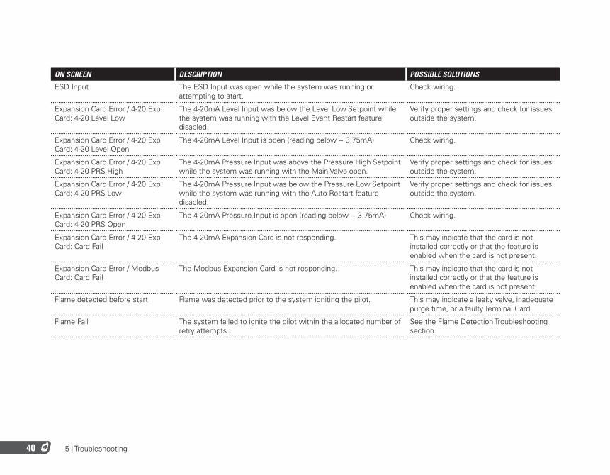
ON SCREEN DESCRIPTION POSSIBLE SOLUTIONS
ESD Input The ESD Input was open while the system was running or attempting to start.
Check wiring.
Expansion Card Error / 4-20 Exp Card: 4-20 Level Low
The 4-20mA Level Input was below the Level Low Setpoint while the system was running with the Level Event Restart feature disabled.
Verify proper settings and check for issues outside the system.
Expansion Card Error / 4-20 Exp Card: 4-20 Level Open
The 4-20mA Level Input is open (reading below ~ 3.75mA) Check wiring.
Expansion Card Error / 4-20 Exp Card: 4-20 PRS High
The 4-20mA Pressure Input was above the Pressure High Setpoint while the system was running with the Main Valve open.
Verify proper settings and check for issues outside the system.
Expansion Card Error / 4-20 Exp Card: 4-20 PRS Low
The 4-20mA Pressure Input was below the Pressure Low Setpoint while the system was running with the Auto Restart feature disabled.
Verify proper settings and check for issues outside the system.
Expansion Card Error / 4-20 Exp Card: 4-20 PRS Open
The 4-20mA Pressure Input is open (reading below ~ 3.75mA) Check wiring.
Expansion Card Error / 4-20 Exp Card: Card Fail
The 4-20mA Expansion Card is not responding. This may indicate that the card is not installed correctly or that the feature is enabled when the card is not present.
Expansion Card Error / Modbus Card: Card Fail
The Modbus Expansion Card is not responding. This may indicate that the card is not installed correctly or that the feature is enabled when the card is not present.
Flame detected before start Flame was detected prior to the system igniting the pilot. This may indicate a leaky valve, inadequate purge time, or a faulty Terminal Card.
Flame Fail The system failed to ignite the pilot within the allocated number of retry attempts.
See the Flame Detection Troubleshooting section.
5 | Troubleshooting 41
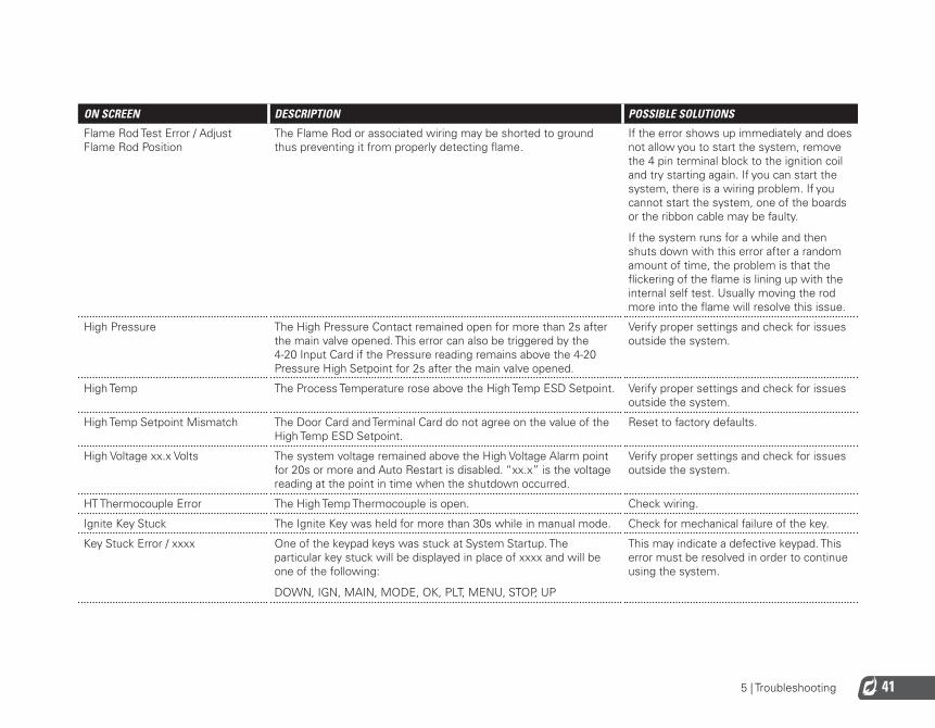
ON SCREEN DESCRIPTION POSSIBLE SOLUTIONS
Flame Rod Test Error / Adjust Flame Rod Position
The Flame Rod or associated wiring may be shorted to ground thus preventing it from properly detecting flame.
If the error shows up immediately and does not allow you to start the system, remove the 4 pin terminal block to the ignition coil and try starting again. If you can start the system, there is a wiring problem. If you cannot start the system, one of the boards or the ribbon cable may be faulty.
If the system runs for a while and then shuts down with this error after a random amount of time, the problem is that the flickering of the flame is lining up with the internal self test. Usually moving the rod more into the flame will resolve this issue.
High Pressure The High Pressure Contact remained open for more than 2s after the main valve opened. This error can also be triggered by the 4-20 Input Card if the Pressure reading remains above the 4-20 Pressure High Setpoint for 2s after the main valve opened.
Verify proper settings and check for issues outside the system.
High Temp The Process Temperature rose above the High Temp ESD Setpoint. Verify proper settings and check for issues outside the system.
High Temp Setpoint Mismatch The Door Card and Terminal Card do not agree on the value of the High Temp ESD Setpoint.
Reset to factory defaults.
High Voltage xx.x Volts The system voltage remained above the High Voltage Alarm point for 20s or more and Auto Restart is disabled. “xx.x” is the voltage reading at the point in time when the shutdown occurred.
Verify proper settings and check for issues outside the system.
HT Thermocouple Error The High Temp Thermocouple is open. Check wiring.
Ignite Key Stuck The Ignite Key was held for more than 30s while in manual mode. Check for mechanical failure of the key.
Key Stuck Error / xxxx One of the keypad keys was stuck at System Startup. The particular key stuck will be displayed in place of xxxx and will be one of the following:
DOWN, IGN, MAIN, MODE, OK, PLT, MENU, STOP, UP
This may indicate a defective keypad. This error must be resolved in order to continue using the system.
5 | Troubleshooting42
ON SCREEN DESCRIPTION POSSIBLE SOLUTIONS
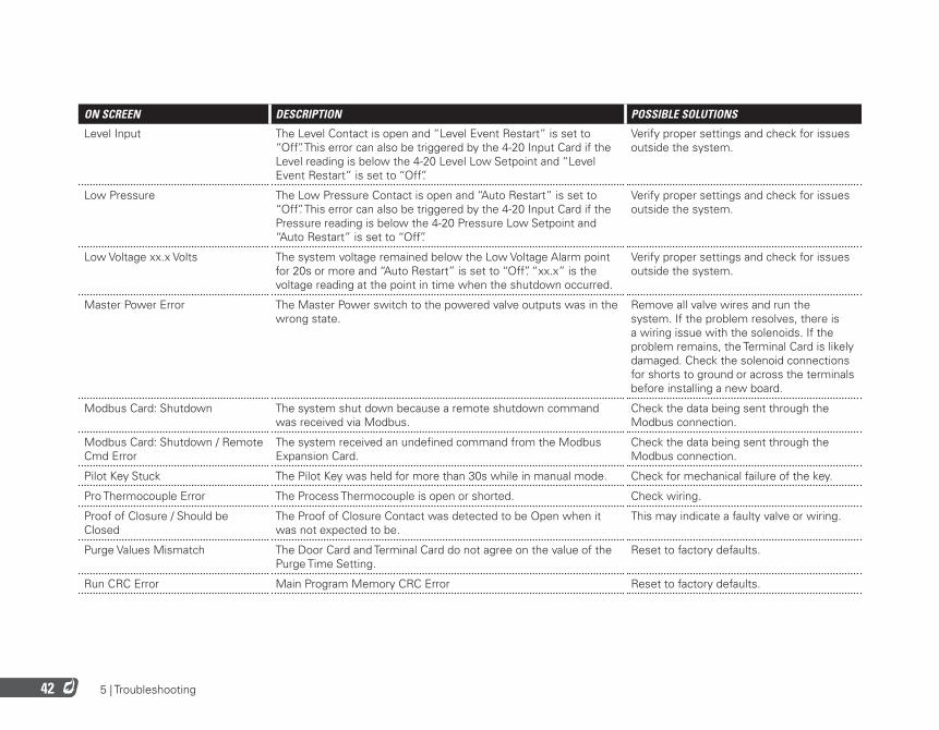
Level Input The Level Contact is open and “Level Event Restart” is set to “Off”. This error can also be triggered by the 4-20 Input Card if the Level reading is below the 4-20 Level Low Setpoint and “Level Event Restart” is set to “Off”.
Verify proper settings and check for issues outside the system.
Low Pressure The Low Pressure Contact is open and “Auto Restart” is set to “Off”. This error can also be triggered by the 4-20 Input Card if the Pressure reading is below the 4-20 Pressure Low Setpoint and “Auto Restart” is set to “Off”.
Verify proper settings and check for issues outside the system.
Low Voltage xx.x Volts The system voltage remained below the Low Voltage Alarm point for 20s or more and “Auto Restart” is set to “Off”. “xx.x” is the voltage reading at the point in time when the shutdown occurred.
Verify proper settings and check for issues outside the system.
Master Power Error The Master Power switch to the powered valve outputs was in the wrong state.
Remove all valve wires and run the system. If the problem resolves, there is a wiring issue with the solenoids. If the problem remains, the Terminal Card is likely damaged. Check the solenoid connections for shorts to ground or across the terminals before installing a new board.
Modbus Card: Shutdown The system shut down because a remote shutdown command was received via Modbus.
Check the data being sent through the Modbus connection.
Modbus Card: Shutdown / Remote Cmd Error
The system received an undefined command from the Modbus Expansion Card.
Check the data being sent through the Modbus connection.
Pilot Key Stuck The Pilot Key was held for more than 30s while in manual mode. Check for mechanical failure of the key.
Pro Thermocouple Error The Process Thermocouple is open or shorted. Check wiring.
Proof of Closure / Should be Closed
The Proof of Closure Contact was detected to be Open when it was not expected to be.
This may indicate a faulty valve or wiring.
Purge Values Mismatch The Door Card and Terminal Card do not agree on the value of the Purge Time Setting.
Reset to factory defaults.
Run CRC Error Main Program Memory CRC Error Reset to factory defaults.
5 | Troubleshooting 43
ON SCREEN DESCRIPTION POSSIBLE SOLUTIONS
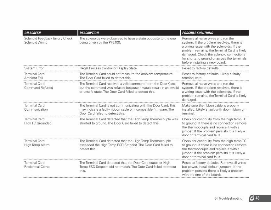
Solenoid Feedback Error / Check Solenoid Wiring
The solenoids were observed to have a state opposite to the one being driven by the PF2100.
Remove all valve wires and run the system. If the problem resolves, there is a wiring issue with the solenoids. If the problem remains, the Terminal Card is likely damaged. Check the solenoid connections for shorts to ground or across the terminals before installing a new board.
System Error Illegal Process Control or Display State Reset to factory defaults.
Terminal Card Ambient Fail
The Terminal Card could not measure the ambient temperature. The Door Card failed to detect this.
Reset to factory defaults. Likely a faulty terminal card.
Terminal Card Command Refused
The Terminal Card received a valid command from the Door Card but the command was refused because it would result in an invalid or unsafe state. The Door Card failed to detect this.
Remove all valve wires and run the system. If the problem resolves, there is a wiring issue with the solenoids. If the problem remains, the Terminal Card is likely damaged.
Terminal Card Communication
The Terminal Card is not communicating with the Door Card. This may indicate a faulty ribbon cable or incompatible firmware. The Door Card failed to detect this.
Make sure the ribbon cable is properly installed. Likely a fault with door, ribbon or terminal.
Terminal Card High TC Grounded
The Terminal Card detected that the High Temp Thermocouple was shorted to ground. The Door Card failed to detect this.
Check for continuity from the high temp TC to ground. If there is no connection remove the thermocouple and replace it with a jumper. If the problem persists it is likely a door or terminal card fault.
Terminal Card High Temp Alarm
The Terminal Card detected that the High Temp Thermocouple exceeded the High Temp ESD Setpoint. The Door Card failed to detect this.
Check for continuity from the high temp TC to ground. If there is no connection remove the thermocouple and replace it with a jumper. If the problem persists it is likely a door or terminal card fault.
Terminal Card Reciprocal Comp
The Terminal Card detected that the Door Card status or High Temp ESD Setpoint did not match. The Door Card failed to detect this.
Reset to factory defaults. Remove all wires but power, install default jumpers. If the problem persists there is likely a problem with the one of the boards.
5 | Troubleshooting44
ON SCREEN DESCRIPTION POSSIBLE SOLUTIONS
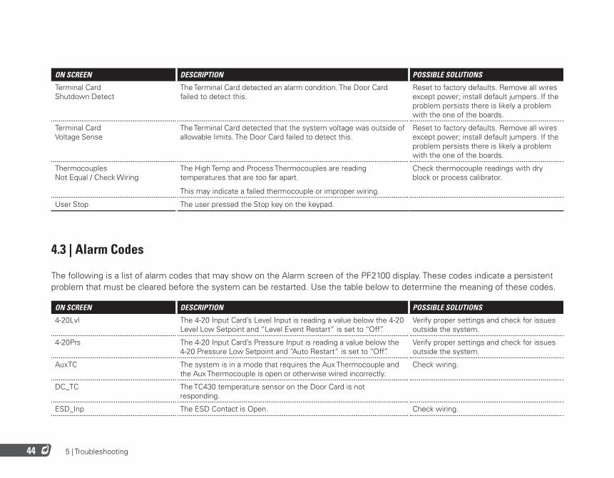
Terminal Card Shutdown Detect
The Terminal Card detected an alarm condition. The Door Card failed to detect this.
Reset to factory defaults. Remove all wires except power; install default jumpers. If the problem persists there is likely a problem with the one of the boards.
Terminal Card Voltage Sense
The Terminal Card detected that the system voltage was outside of allowable limits. The Door Card failed to detect this.
Reset to factory defaults. Remove all wires except power; install default jumpers. If the problem persists there is likely a problem with the one of the boards.
Thermocouples Not Equal / Check Wiring
The High Temp and Process Thermocouples are reading temperatures that are too far apart.
This may indicate a failed thermocouple or improper wiring.
Check thermocouple readings with dry block or process calibrator.
User Stop The user pressed the Stop key on the keypad.
4.3 | Alarm Codes
The following is a list of alarm codes that may show on the Alarm screen of the PF2100 display. These codes indicate a persistent problem that must be cleared before the system can be restarted. Use the table below to determine the meaning of these codes.
ON SCREEN DESCRIPTION POSSIBLE SOLUTIONS
4-20Lvl The 4-20 Input Card’s Level Input is reading a value below the 4-20 Level Low Setpoint and “Level Event Restart” is set to “Off”.
Verify proper settings and check for issues outside the system.
4-20Prs The 4-20 Input Card’s Pressure Input is reading a value below the 4-20 Pressure Low Setpoint and “Auto Restart” is set to “Off”.
Verify proper settings and check for issues outside the system.
AuxTC The system is in a mode that requires the Aux Thermocouple and the Aux Thermocouple is open or otherwise wired incorrectly.
Check wiring.
DC_TC The TC430 temperature sensor on the Door Card is not responding.
ESD_Inp The ESD Contact is Open. Check wiring.
5 | Troubleshooting 45
ON SCREEN DESCRIPTION POSSIBLE SOLUTIONS
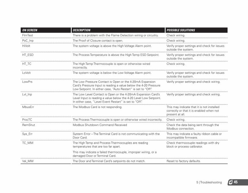
FlmTest There is a problem with the Flame Detection wiring or circuitry. Check wiring.
PoC_Inp The Proof of Closure contact is open. Check wiring.
HiVolt The system voltage is above the High Voltage Alarm point. Verify proper settings and check for issues outside the system.
HT_ESD The Process Temperature is above the High Temp ESD Setpoint. Verify proper settings and check for issues outside the system.
HT_TC The High Temp Thermocouple is open or otherwise wired incorrectly.
Check wiring.
LoVolt The system voltage is below the Low Voltage Alarm point. Verify proper settings and check for issues outside the system.
LowPrs The Low Pressure Contact is Open or the 4-20mA Expansion Card’s Pressure Input is reading a value below the 4-20 Pressure Low Setpoint. In either case, “Auto Restart” is set to “Off”.
Verify proper settings and check wiring.
Lvl_Inp The Low Level Contact is Open or the 4-20mA Expansion Card’s Level Input is reading a value below the 4-20 Level Low Setpoint. In either case, “Level Event Restart” is set to “Off”.
Verify proper settings and check wiring.
MbusErr The Modbus Card is not responding. This may indicate that it is not installed correctly or that it is enabled when not present at all.
ProcTC The Process Thermocouple is open or otherwise wired incorrectly. Check wiring.
RemShut Modbus Shutdown Command Received Check the data being sent through the Modbus connection.
Sys_Err System Error – The Terminal Card is not communicating with the Door Card.
This may indicate a faulty ribbon cable or incompatible firmware.
TC_MM The High Temp and Process Thermocouples are reading temperatures that are too far apart.
This may indicate a failed thermocouple, improper wiring, or a damaged Door or Terminal Card.
Check thermocouple readings with dry block or process calibrator.
Val_MM The Door and Terminal Card’s setpoints do not match. Reset to factory defaults.

5 | Troubleshooting46
4.4 | Warning Messages
The following is a list of warning messages that may flash periodically on the PF2100 display. These messages indicate a problem that may be developing or a condition from which the system may automatically restart once cleared. Use the table below to determine the meaning of these messages.
ON SCREEN DESCRIPTION
Check all settings / Other settings have changed
A major process control setting was changed and the process control setpoints were reset to factory defaults. This includes the High Temp ESD Setpoint, the Pilot Off Setpoint, the Low Fire Setpoint, the Process Setpoint, the Low Temp Alarm Setpoint, the Deadband setting, and the Aux Setpoint.
HI Volt Warning The system voltage is getting close to the High Voltage Alarm threshold and may stop or shutdown soon.
High Prs Warning The High Pressure Contact is open or the 4-20 Pressure Input is above the 4-20 Pressure High Setpoint. The contact must be closed shortly after the main valve opens and the 4-20 Pressure is below the setpoint or the system will shutdown.
LO Volt Warning The system voltage is getting close to the Low Voltage Alarm threshold and may stop or shutdown soon.
Low Temp Alarm The process temperature is below the Low Temp Alarm Setpoint and the Status Contact is Open.
Unit restarted from LVL event The system has recently restarted from a Level event. Press OK to clear this message.
Unit restarted from PRS event The system has recently restarted from a Low Pressure event. Press OK to clear this message.
Unit restarted from VLT event The system has recently restarted from a Low or High Voltage event. Press OK to clear this message.
Waiting: 420 LVL The system will automatically restart once the 4-20 Input Card’s Level Input rises above the Low Setpoint.
Waiting: 420 PRS The system will automatically restart once the 4-20 Input Card’s Pressure Input drops below the High Setpoint.
Waiting: HiVolt The system will automatically restart once the system voltage falls below the High Voltage Alarm Threshold.
Waiting: LoVolt The system will automatically restart once the system voltage rises above the Low Voltage Alarm Threshold.
Waiting: Low PRS The system will automatically restart once the Low Pressure Contact is closed.
Waiting: LVL The system will automatically restart once the Level Contact is closed.
Waiting:STRT Inp The system will automatically restart once the Start Contact is closed.
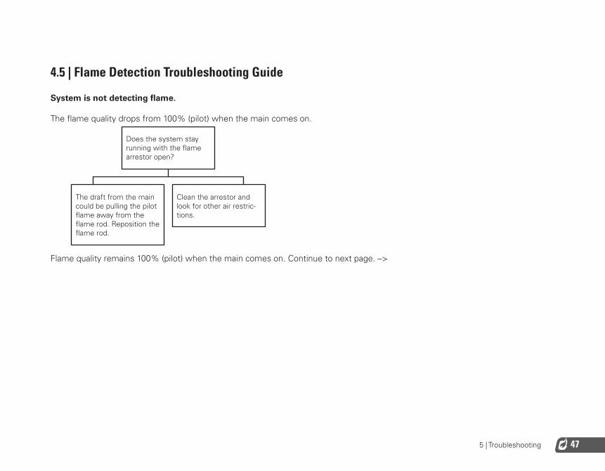
5 | Troubleshooting 47
4.5 | Flame Detection Troubleshooting Guide
System is not detecting flame.
The flame quality drops from 100% (pilot) when the main comes on. Does the system stay running with the flame arrestor open?
The draft from the main could be pulling the pilot flame away from the flame rod. Reposition the flame rod.
Clean the arrestor and look for other air restric-tions.
Flame quality remains 100% (pilot) when the main comes on. Continue to next page. –>

5 | Troubleshooting48
Flame quality remains 100% (pilot) when the main comes on. Make sure that the pilot orifice is correct for the gas used. (#54 for natural gas)
Make sure that there is a metal-on-metal connection from the pilot noz-zle to the housing and a ground wire from the housing to the PF2100.
Make sure that the ignition rod is fully immersed in the flame.
Take note of the maximum voltage.
Is the voltage greater than 25VAC?
Remove the wire from ION+ and measure the AC voltage between the ION + and ION - terminals again.
Is the voltage above 35VAC?
Measure the AC voltage from the flame rod to ground if the rod is accessible. If it is not accessible, remove the wire from the flame rod and measure on the connector.
Is the voltage measure at the rod close to the voltage measure across the ION + and ION - terminals?
It is possible that the terminal card is faulty.
Is the wire run length from the burner to the PF2100 longer than 25 ft?
Please continue to Flow Chart 1 on next page.
Please continue to Flow Chart 2 on next page.
Something is loading the signal. Make sure that the wire type is not shielded. Look for partial ground shorts or nicked wires.
The length loading on the wire is too high. Using ignition wire for ION + will allow the signal to be run up to 50 ft. Using separate rods for flame detection and ignition can also reduce the ION + load by bypassing the coil.
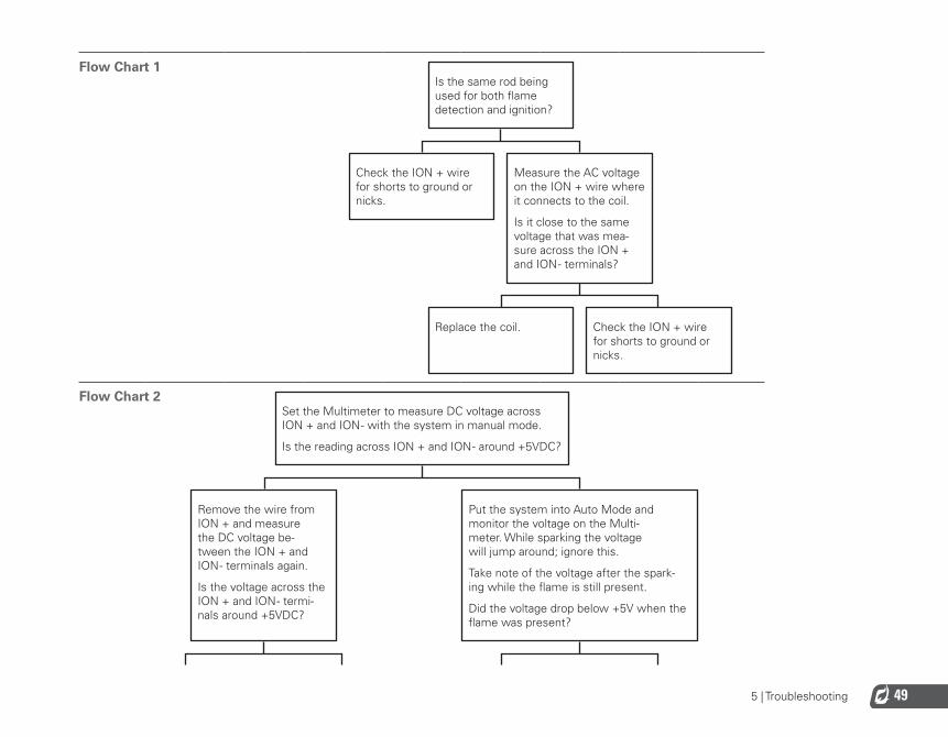
5 | Troubleshooting 49
Flow Chart 1 Is the same rod being used for both flame detection and ignition?
Check the ION + wire for shorts to ground or nicks.
Measure the AC voltage on the ION + wire where it connects to the coil.
Is it close to the same voltage that was mea-sure across the ION + and ION - terminals?
Replace the coil.
Check the ION + wire for shorts to ground or nicks.
Flow Chart 2 Set the Multimeter to measure DC voltage across ION + and ION - with the system in manual mode.
Is the reading across ION + and ION - around +5VDC?
Remove the wire from ION + and measure the DC voltage be-tween the ION + and ION - terminals again.
Is the voltage across the ION + and ION - termi-nals around +5VDC?
Put the system into Auto Mode and monitor the voltage on the Multi-meter. While sparking the voltage will jump around; ignore this.
Take note of the voltage after the spark-ing while the flame is still present.
Did the voltage drop below +5V when the flame was present?
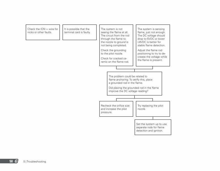
5 | Troubleshooting50
Check the ION + wire for nicks or other faults.
It is possible that the terminal card is faulty.
The system is not seeing the flame at all. The circuit from the rod through the flame to the nozzle to ground is not being completed.
Check the grounding to the pilot nozzle.
Check for cracked ce-ramic on the flame rod.
The system is sensing flame, just not enough. The DC voltage should drop to -5VDC or lower (-8VDC is better for stable flame detection.
Adjust the flame rod positioning to try to de-crease the voltage while the flame is present.
The problem could be related to flame anchoring. To verify this, place a grounded rod in the flame.
Did placing the grounded rod in the flame improve the DC voltage reading?
Recheck the orifice size and increase the pilot pressure.
Try replacing the pilot nozzle.
Set the system up to use separate rods for flame detection and ignition.
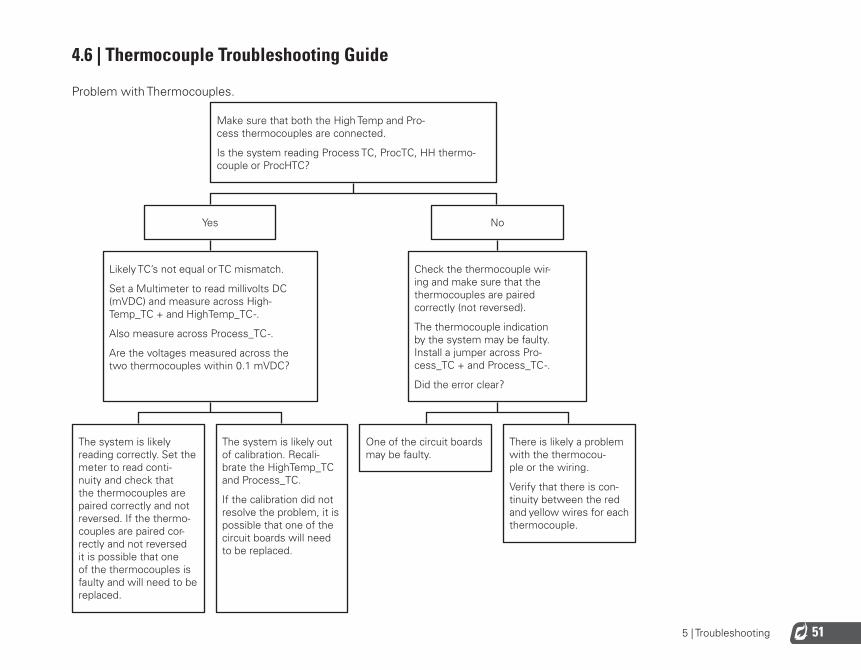
5 | Troubleshooting 51
4.6 | Thermocouple Troubleshooting Guide
Problem with Thermocouples. Make sure that both the High Temp and Pro-cess thermocouples are connected.
Is the system reading Process TC, ProcTC, HH thermo-couple or ProcHTC?
Yes
No
Likely TC’s not equal or TC mismatch.
Set a Multimeter to read millivolts DC (mVDC) and measure across High-Temp_TC + and HighTemp_TC -.
Also measure across Process_TC -.
Are the voltages measured across the two thermocouples within 0.1 mVDC?
Check the thermocouple wir-ing and make sure that the thermocouples are paired correctly (not reversed).
The thermocouple indication by the system may be faulty. Install a jumper across Pro-cess_TC + and Process_TC -.
Did the error clear?
The system is likely reading correctly. Set the meter to read conti-nuity and check that the thermocouples are paired correctly and not reversed. If the thermo-couples are paired cor-rectly and not reversed it is possible that one of the thermocouples is faulty and will need to be replaced.
The system is likely out of calibration. Recali-brate the HighTemp_TC and Process_TC.
If the calibration did not resolve the problem, it is possible that one of the circuit boards will need to be replaced.
One of the circuit boards may be faulty.
There is likely a problem with the thermocou-ple or the wiring.
Verify that there is con-tinuity between the red and yellow wires for each thermocouple.
52
Tune the Proportional Band Setting
1. Start with the Proportional Band Setting set to a large value such as 500% and with the Integral and Derivative settings set to their default values (4.0min/rst and 0.0min respectively).
2. Make a small step change (such as 5%) to the Process Setpoint and monitor the resulting temperature change.
3. Repeat decreasing the Proportional Band Setting in 50% steps until a Process Setpoint change results in overshoot of the Process Setpoint or until oscillation results.
4. Increase the Proportional Band Setting until overshoot and oscillation no longer occur.
Tune the Integral Setting
1. Set the Integral setting to 10min/rst.
2. Make a small change to the Process Setpoint and monitor the temperature change.
3. Repeat decreasing the Integral in ½ minute steps until a Process Setpoint change results in overshoot of the Process Setpoint or until oscillation results.
4. Increase the Integral Setting until stable.
Tune the Derivative Setting
If there is noise on the thermocouple inputs, using the Derivative Setting can dampen the effects of the Proportional and Integral Settings. For this reason, the Derivative Setting can usually be left set at zero unless a very fast response is needed. If required, follow this tuning procedure:
1. Set the Derivative Setting to 10 minutes.
2. Decrease the Derivative Setting until a small Process Setpoint change results in a fast response with some oscillation.
3. Increase the Derivative Setting until the oscillation in response to a Process Setpoint change is dampened.
5 | Appendix A: PID TuningThe PF2100’s default PID settings should result in good temperature control in most common heater applications. If the temperature control is unstable or if a faster control response is needed, this procedure can be followed to adjust the PID settings. This procedure does not cover all scenarios for adjusting PID Controllers but provides some general guidelines. Note that this procedure involves some tuning and may require a significant amount of time to follow.

53
6 | Appendix B: Field CalibrationIt is possible to field calibrate the thermocouples, the 4-20mA Output, and the two 4-20mA Inputs on the 4-20mA Expansion Card. In general, it should not be necessary to do this in the field because the system has already been calibrated at the factory. However, there are circumstances where this may be necessary such as if the door or terminal card was replaced in the field or if the system is very old and has drifted out of calibration. Before recalibrating the system, it is strongly recommended that you explore all other possible solutions first. For example, verify that system settings are correct and that the devices attached to the system are calibrated correctly. If it is deemed necessary to proceed with recalibrating the PF2100, follow the procedures below carefully. Failure to perform the calibration correctly may result in worse performance than if the system had been left alone.
The PF2100 uses a two-point calibration system to provide readings with greater accuracy than a single-point offset calibration. The first point compensates for any fixed offset in the system and the second point defines the slope. If the calibration fails for any reason, there is an option in the calibration menu to clear all calibration data.
CALIBRATING THE THERMOCOUPLES
For thermocouples, the first calibration point is zero volts which corresponds to the ambient temperature of the terminal block where the thermocouple plugs into the Terminal Card. The second calibration point is referenced to a known temperature that is well above the ambient temperature. This temperature is typically the hottest temperature at which the system will operate but should not be higher than 1350˚C and should not be lower than ambient + 20˚C.
1. Make sure that the system is stopped.
2. Remove the 3 pairs of thermocouple wires (High Temp, Process, and Aux) from the P8 Pluggable Header on the Terminal Card.
3. Short each pair of thermocouple inputs individually using a jumper or short piece of copper wire (ie, short HT+ to HT-, short Proc+ to Proc-, and short Aux+ to Aux-).
4. Press the UP and Down keys simultaneously to unlock the
Calibration Menu (Menu 7) which is normally hidden.
5. Press the Menu Key repeatedly until Menu 7 is shown.
6. Press OK. If prompted, enter the L2 Password:
7. “Cal Proc TC Zero” will show on the display.
8. Press OK and the message “Calibrating Wait…” will appear on the display for about 5 seconds. Afterwards, the message “Parameter Saved” will show on the display briefly.
54
9. Press the Menu key to go to the next item.
10. Repeat steps 8 and 9 for the “Cal HiTemp TC Zero” and “Cal Aux TC Zero” menu items.
11. Reconnect the 3 pairs of thermocouple wires (High Temp, Process, and Aux) to the P8 Pluggable Header on the Terminal Card.
12. Set the High Temp, Process, and Aux thermocouples to a known reference temperature using a dry block or other calibrated reference. The reference temperature should be at least 20˚C above the ambient temperature and preferably close to the maximum planned operating temperature.
13. “Cal Proc TC Span” will show on the display.
14. Use the Up and Down keys to adjust the temperature
displayed on the PF2100 to match the temperature being applied to the thermocouple. Note that multiple key presses may be required before the temperature value on the display changes. This is because each key press is adjusting a fractional multiplication factor internal to the system.
15. Press OK and the message “Parameter Saved” will show on the display briefly.
16. Press the Menu key to go to the next item.
17. Repeat steps 14-16 for the “Cal HiTemp TC Span” and “Cal Aux TC Span” menu items.
18. Press and hold the OK key for 3 seconds until the message “Password Logout” is displayed on the screen. The Calibration Menu is now hidden again.
CALIBRATING THE 4-20MA OUTPUT
For the 4-20mA Output, the first calibration point is 4mA and the second calibration point is 20mA. You will need a current meter capable of measuring current to 0.1mA accuracy.
1. Make sure that the system is stopped.
2. Connect a current meter in series with the 4-20mA Output.
3. Set the current meter to a range setting that covers both 4mA and 20mA.
4. Press the UP and Down Keys simultaneously to unlock the Calibration Menu (Menu 7) which is normally hidden.
5. Press the Menu key repeatedly until Menu 7 is shown.
6. Press OK. If prompted, enter the L2 Password:
7. Press the Menu key repeatedly until “Cal 4-20 Out Zero” is shown on the display.
8. Use the Up and Down keys to adjust the output current until the current meter reads 4.0mA.
9. Press OK and the message “Parameter Saved” will show on the display briefly.
10. Press the Menu key repeatedly until “Cal 4-20 Out Span” is shown on the display.
55
11. Use the Up and Down keys to adjust the output current until the current meter reads 20.0mA.
12. Press OK and the message “Parameter Saved” will show on the display briefly.
13. Press and hold the OK key for 3 seconds until the message “Password Logout” is displayed on the screen. The Calibration Menu is now hidden again.
CALIBRATING THE 4-20MA INPUTS
For the 4-20mA Input, the first calibration point is 4mA and the second calibration point is 20mA. You will need a handheld process calibrator such as the Fluke 725.
1. Make sure that the system is stopped.
2. Make sure the card is installed and enabled in menu 6. The LVL and PRS DIP switches must also be enabled on the card.
3. Press the UP and DOWN Keys.
4. Press the Menu Key repeatedly until Menu 7 is shown.
5. Press OK. If prompted, enter the L2 Password:
6. Connect the process calibrator’s negative lead to the ground pin on the 4-20mA Input Card.
7. Calibrate the Level Zero:
• Press the Menu Key repeatedly until “4-20 Level Zero Calibration = No” is shown on the display.
• Use the Up or Down key to select “Yes” and begin the calibration process. The display will now read “Apply 4mA then press OK”.
• Disconnect any wiring connected to the Level input and instead attach the process calibrator’s positive lead in its
place.• Turn on the process calibrator and set it to source a
current of 4mA (0%).• Press the OK key and the message “Calibrating Wait…”
will appear for several seconds followed by the message “Parameter Set” after the calibration has successfully completed.
8. Calibrate the Level Input’s Span point:
• Press the Menu key repeatedly until “Calibrate 4-20 LVL Span?” is shown on the display.
• Use the Up or Down key to select “Yes” and begin the calibration process. The display will now read “Apply 20mA then press OK”.
• Set the process calibrator to source a current of 20mA (100%).
• Press the OK key and the message “Calibrating Wait…” will appear for several seconds followed by the message “Parameter Set” after the calibration has successfully completed.

56
• Disconnect the process calibrator from the Level input and reconnect any wiring that was removed from it previously.
9. Calibrate the Pressure Input’s Zero point:
• Press the Menu Key repeatedly until “Calibrate 4-20 PRS Zero?” is shown on the display.
• Use the Up or Down key to select “Yes” and begin the calibration process. The display will now read “Apply 4mA then press OK”.
• Disconnect any wiring connected to the Pressure input and instead attach the process calibrator’s positive lead in its place.
• Turn on the process calibrator and set it to source a current of 4mA (0%).
• Press the OK key and the message “Calibrating Wait…” will appear for several seconds followed by the message “Parameter Set” after the calibration has successfully completed.
10. Calibrate the Pressure Input’s Span point:
• Press the Menu Key repeatedly until “Calibrate 4-20 PRS Span?” is shown on the display.
• Use the Up or Down key to select “Yes” and begin the calibration process. The display will now read “Apply 20mA then press OK”.
• Set the process calibrator to source a current of 20mA (100%).
• Press the OK key and the message “Calibrating Wait…” will appear for several seconds followed by the message “Parameter Set” after the calibration has successfully completed.
• Disconnect the process calibrator from the Pressure input and reconnect any wiring that was removed from it previously.
11. Disconnect the process calibrator’s negative lead from the ground pin on the 4-20mA Input Card.

57
RESETTING CALIBRATION DATA
If you want to reset the calibration settings to default, use the “Cal Data” option at the end of Menu 7.
This process resets the following calibrations to defaults:
1. Calibration of the Thermocouples
2. Calibration of the 4-20mA Output
3. Calibration of the 4-20mA Intput
1. Make sure that the system is stopped.
2. Press the Up and Down Keys simultaneously to unlock the Calibration Menu (Menu 7) which is normally hidden.
3. Press the Menu key repeatedly until Menu 7 is shown.
4. Press OK. If prompted, enter the L2 Password:
5. Press the Menu key repeatedly until “Cal Data” is shown on the display
6. Use the Up or Down keys to select “Yes”.
7. Press OK and the message “Parameter Saved” will show on the display briefly.
8. Press and hold the OK key for 3 seconds until the message “Password Logout” is displayed on the screen. The Calibration Menu is now hidden again.

58
CALIBRATION (MENU 7)
This menu is used to adjust the calibration of thermocouples, 4-20mA Output, and 4-20mA Expansion Card inputs. This menu is hidden by default.
MENU MAP ON SCREEN BRIEF DESCRIPTION RANGE DEFAULT SETTING CUSTOM SETTINGS
Cal Process TC Zero Cal Proc TC Zero?
Calibrate Process Thermocouple zero point by shorting the Input
N/A N/A
Cal High Temp TC Zero Cal HiTemp TC Zero?
Calibrate High Temp Thermocouple zero point by shorting the Input
N/A N/A
Cal Aux TC Zero Cal AUX TC Zero?
Calibrate Aux Thermocouple zero point by shorting the Input
N/A N/A
Cal Process TC Span Cal Proc TC Span: xxC
Calibrate Process Thermocouple span point by applying a calibrated reference then adjust the on screen value
N/A N/A
Cal High Temp TC Span Cal HiTemp TC Span: xxC
Calibrate High Temp Thermocouple span point by applying a calibrated reference then adjust the on screen value
N/A N/A
Cal Aux TC Span Cal AUX TC Span: xxC
Calibrate Aux Thermocouple span point by applying a calibrated reference then adjust the on screen value
N/A N/A
Cal 4-20 Level Zero Calibrate 4-20 LVL Zero?
Calibrate 4-20mA Level Input zero point by applying a calibrated 4mA reference
N/A N/A
Cal 4-20 Level Span Calibrate 4-20 LVL Span?
Calibrate 4-20mA Level Input span point by applying a calibrated 20mA reference
N/A N/A
Cal 4-20 Pressure Zero Calibrate 4-20 PRS Zero?
Calibrate 4-20mA Pressure Input zero point by applying a calibrated 4mA reference
N/A N/A
Cal 4-20 Pressure Span Calibrate 4-20 PRS Span?
Calibrate 4-20mA Pressure Input span point by applying a calibrated 20mA reference
N/A N/A
Cal 4-20 Out Zero Cal 4-20 Out Zero: x
Calibrate 4-20mA Output zero point by adjusting until a multimeter reads 4mA
N/A N/A
Cal 4-20 Out Span Cal 4-20 Out Span: x
Calibrate 4-20mA Output zero point by adjusting until a multimeter reads 20mA
N/A N/A
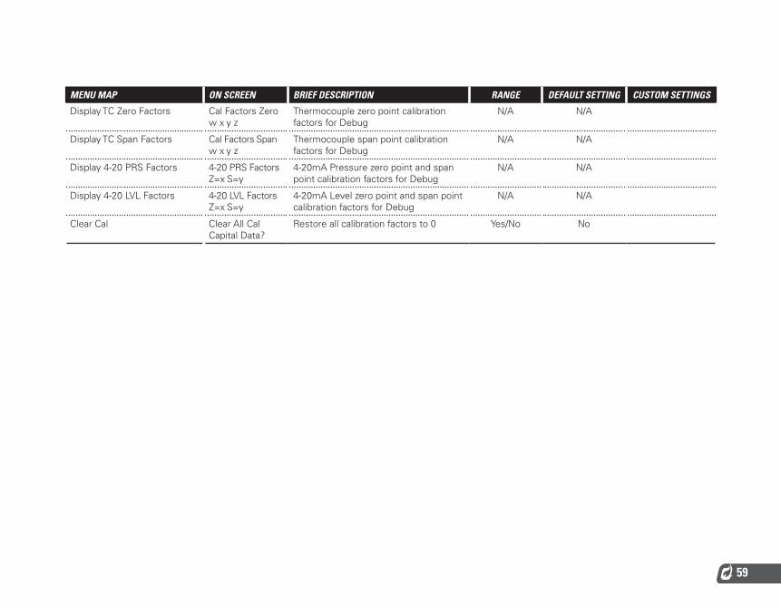
59
MENU MAP ON SCREEN BRIEF DESCRIPTION RANGE DEFAULT SETTING CUSTOM SETTINGS
Display TC Zero Factors Cal Factors Zero w x y z
Thermocouple zero point calibration factors for Debug
N/A N/A
Display TC Span Factors Cal Factors Span w x y z
Thermocouple span point calibration factors for Debug
N/A N/A
Display 4-20 PRS Factors 4-20 PRS Factors Z=x S=y
4-20mA Pressure zero point and span point calibration factors for Debug
N/A N/A
Display 4-20 LVL Factors 4-20 LVL Factors Z=x S=y
4-20mA Level zero point and span point calibration factors for Debug
N/A N/A
Clear Cal Clear All Cal Capital Data?
Restore all calibration factors to 0 Yes/No No
60
7 | Appendix C: Resetting to DefaultsThe system settings can all be reset to factory defaults by following these instructions:
1. Make sure that the system is stopped.
2. Navigate to the “Reset to Factory Defaults” menu item at the bottom of Menu 4.
3. Use the Arrow keys to change the setting to “Yes” and then press the OK key.
4. The system will display “Parameter Saved” and will then reboot.
After rebooting, the system will display the message “CONFIGURATION RESET TO DEFAULT” alternating with “Check Settings and Setpoints.”
5. Press the OK key to acknowledge this warning.
This process only resets the user settings back to factory defaults and does not affect the calibration settings. To reset the calibration settings to defaults, refer to the Field Calibration section.
Note that older versions of firmware did reset both the user settings and the calibration settings to defaults.
Also note that all settings are stored on the Door Card. If the Door Card is replaced for any reason, the settings will need to be re-entered and calibration may need to be performed.

www.profireenergy.com© 2015 PROFIRE


