Instruments, Valves, and Controls Thank You for Attending Today’s Webinar Your Host Mike DeLacluyse President Lesman Instrument Company [email protected]Today’s Featured Speaker A.J. Piskor Combustion & Controls Specialist Lesman Instrument Company [email protected]
• Topics we will cover today:–Components within the Fuel Train–Arrangement of Components–Best Practices for each component–Valve Proving vs. Vent Valve–Leak Testing for Shut-Off Valves–Your Questions
Instruments, Valves, and Controls
Fuel Trains 101
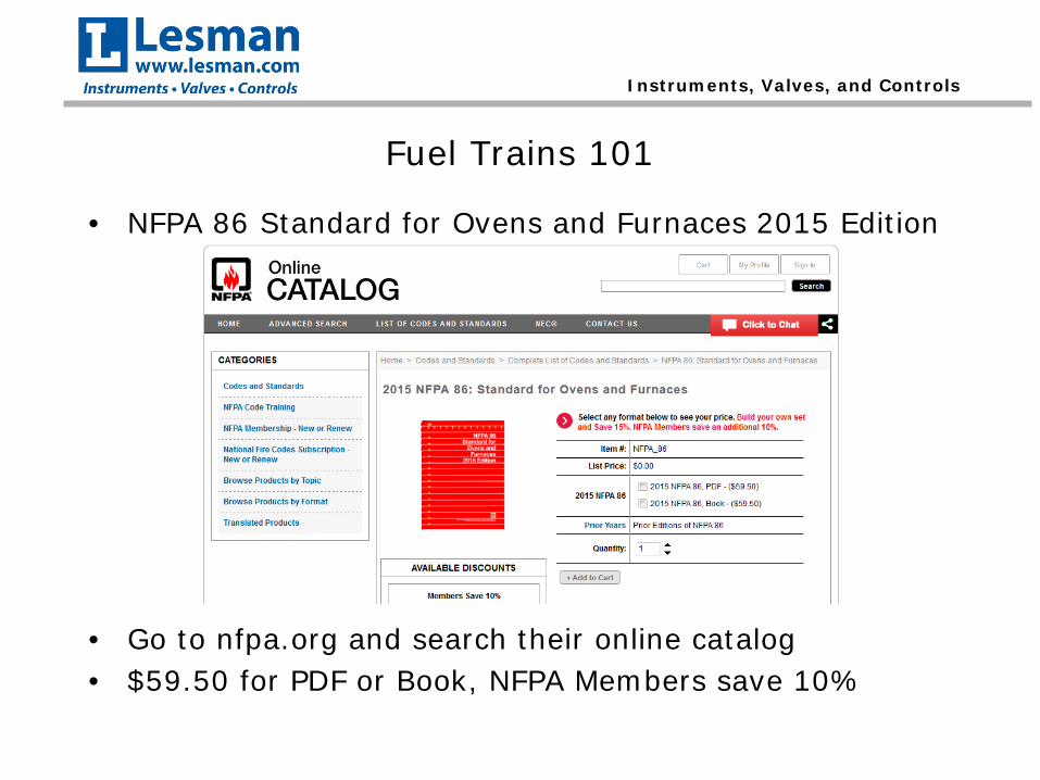
• NFPA 86 Standard for Ovens and Furnaces 2015 Edition
• Go to nfpa.org and search their online catalog• $59.50 for PDF or Book, NFPA Members save 10%
Instruments, Valves, and Controls
Common Themes within NFPA 86
• Devices shall be listed for the service intended.–Can’t use an air switch on a gas line.
• Devices shall be applied and installed in accordance with the manufacturer’s instructions.–Same applies for maintenance.
Instruments, Valves, and Controls
What is the purpose of a Fuel Train?
• The main purpose of a Fuel Train is to safely introduce and interrupt the fuel supply to the burner by:–Regulating the Fuel Pressure–Monitoring the Fuel Pressure–Turning the Fuel ON and OFF
Instruments, Valves, and Controls
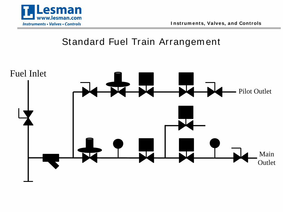
Standard Fuel Train Arrangement
Fuel Inlet
Pilot Outlet
Main Outlet
Instruments, Valves, and Controls
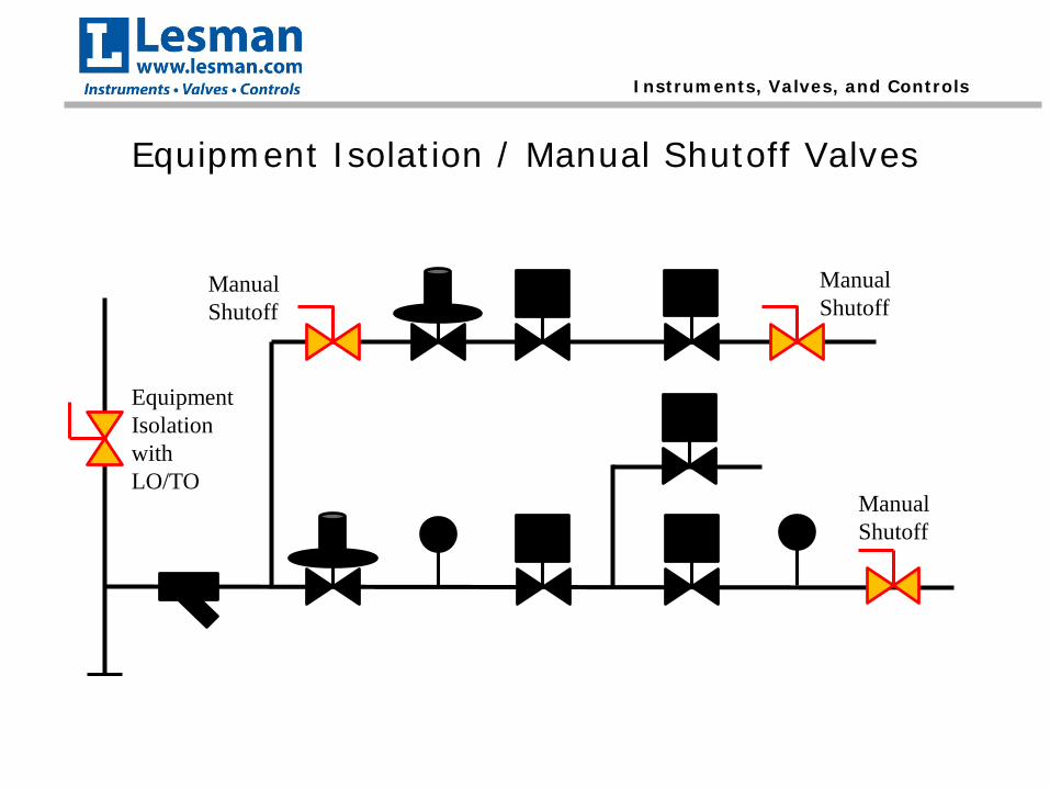
Equipment Isolation / Manual Shutoff Valves
Instruments, Valves, and Controls
Equipment Isolation / Manual Shutoff Valves
• NFPA 86 3.3.78.3 Equipment Isolation Valve. A manual shutoff valve for the shutoff of the fuel to each piece of equipment.
• NFPA 86 3.3.78.4 Emergency Shutoff Valve. A manual shutoff valve to allow the fuel to be turned off in an emergency.
Instruments, Valves, and Controls
Equipment Isolation / Manual Shutoff Valves
• For both Equipment Isolation and Emergency Shutoff, the following shall apply (NFPA 86 6.2.3):– They shall be readily accessible.– They shall have permanently affixed visual indication
of the valve position.– They shall be able to be operated from full open to
full close and return without the use of tools.• These are typically quarter-turn valves with
stops.
Instruments, Valves, and Controls
Equipment Isolation / Manual Shutoff Valves
Manual Shutoff
Equipment Isolation with LO/TO
Manual Shutoff
Manual Shutoff
Instruments, Valves, and Controls
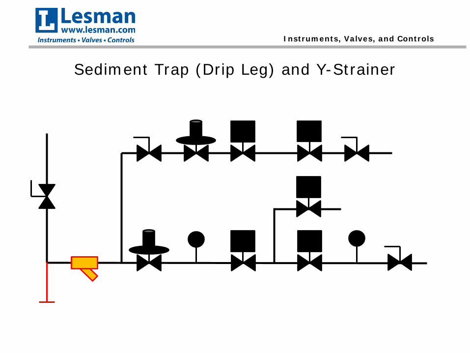
Sediment Trap (Drip Leg) and Y-Strainer
Instruments, Valves, and Controls
Sediment Trap (Drip Leg)
• NFPA 86 6.2.5.2 Sediment traps shall have a vertical leg with a minimum length of three pipe diameters (minimum of 3 in.) of the same size as the supply pipe.
• Main purpose is to catch any larger particulate matter and/or condensation in fuel supply.
• Can install “blow-down” valve at the bottom of the trap for easy cleaning.
Instruments, Valves, and Controls
Y-Strainer / Gas Filter
• NFPA 86 6.2.5.3 A gas filter or strainer shall be installed in the fuel gas piping and shall be located downstream of the equipment isolation valve and sediment trap and upstream of all other fuel gas system components.
• Captures smaller particulate matter that got past the sediment trap.
• Can also have a “blow-down” valve for easy cleaning.
Instruments, Valves, and Controls
Pressure Regulators
Instruments, Valves, and Controls
Pressure Regulators
• NFPA 86 3.3.54 Pressure Regulator. A device placed in a gas line for reducing, controlling, and maintaining the pressure in that portion of the piping system downstream of the device.– 3.3.54.1 Line Pressure Regulator. A pressure regulator
placed in a gas line between the service regulator and the appliance (equipment) regulator.
– 3.3.54.2 Monitoring Pressure Regulator. A pressure regulator in a nonregulated state and set in series with another pressure regulator for the purpose of automatically taking over, in an emergency, control of the pressure downstream of the regulator in cases where pressure exceeds a set maximum.
Instruments, Valves, and Controls
Pressure Regulators (cont.)
– 3.3.54.3 Series Pressure Regulator. A pressure regulator in series with one service or line pressure regulator.
– 3.3.54.4 Service Pressure Regulator. A pressure regulator installed by the servicing gas supplier to reduce and limit the service line gas pressure to delivery pressure.
Instruments, Valves, and Controls
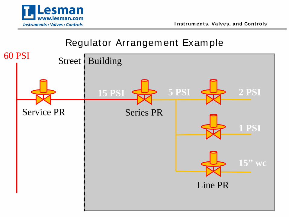
Regulator Arrangement Example60 PSI
15 PSI 5 PSI 2 PSI
1 PSI
15” wc
Street Building
Service PR Series PR
Line PR
Instruments, Valves, and Controls
Overpressure Protection
• NFPA 86 6.2.7.1 Overpressure protection shall be provided in either of the following cases:– (1) When the supply pressure exceeds the
pressure rating of any downstream component
– (2) When the failure of a single upstream line regulator or service pressure regulator results in a supply pressure exceeding the pressure rating of any downstream component.
Instruments, Valves, and Controls
Overpressure Protection
• NFPA 86 6.2.7.2 Overpressure protection shall be provided by any one of the following:– (1) A series regulator in combination with a line
regulator or service pressure regulator– (2) A monitoring regulator installed in combination
with a line regulator or service pressure regulator– (3) A full-capacity pressure relief valve– (4) An overpressure cutoff device, such as a slam-
shut valve or a high-pressure switch in combination with an adequately rated shutoff valve
Instruments, Valves, and Controls
Pressure Regulators – Best Practices
• For high inlet pressures (over 15 PSIG) and low outlet pressures (under 1 PSIG), consider using a piloted regulator.
• Piloted regulators have internal sensing, eliminating the need for long downstream sensing lines.
• Typically react faster to flow changes versus downstream sensing regulators.
Instruments, Valves, and Controls
Pressure Regulators – Best Practices
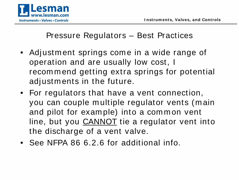
• Adjustment springs come in a wide range of operation and are usually low cost, I recommend getting extra springs for potential adjustments in the future.
• For regulators that have a vent connection, you can couple multiple regulator vents (main and pilot for example) into a common vent line, but you CANNOT tie a regulator vent into the discharge of a vent valve.
• See NFPA 86 6.2.6 for additional info.
Instruments, Valves, and Controls
Proper Venting of Regulators
Instruments, Valves, and Controls
Incorrect Venting of Regulators
Instruments, Valves, and Controls
Fuel Pressure Switches
Instruments, Valves, and Controls
Fuel Pressure Switches
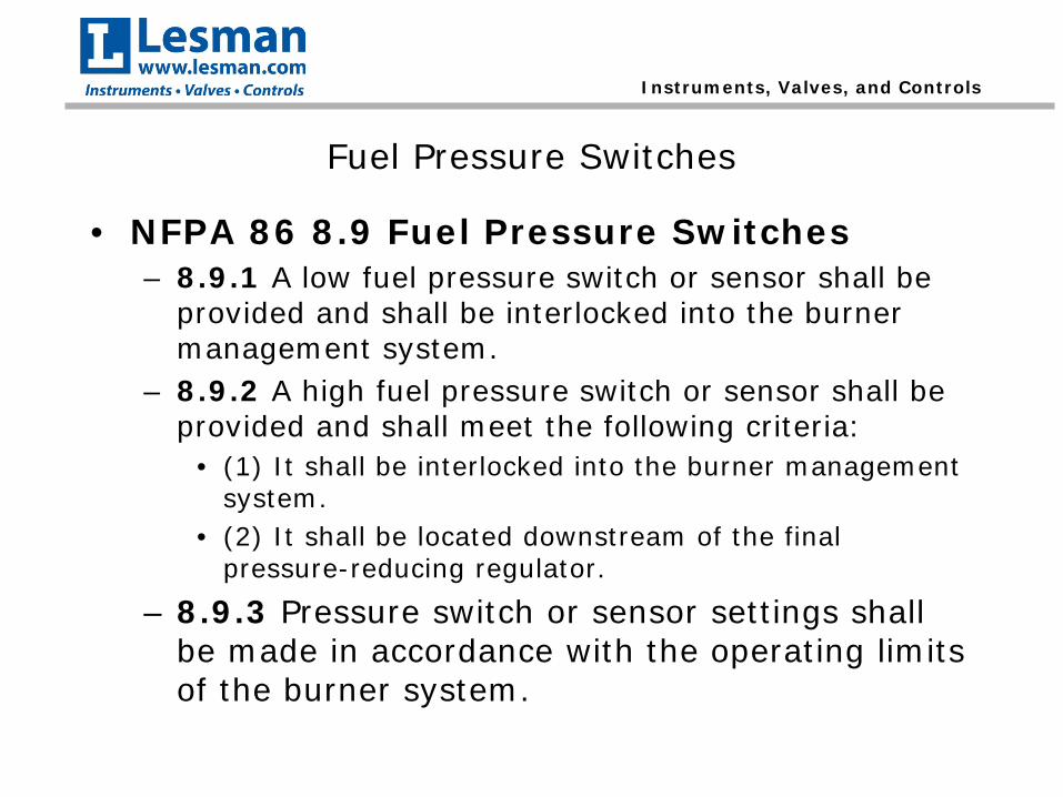
• NFPA 86 8.9 Fuel Pressure Switches– 8.9.1 A low fuel pressure switch or sensor shall be
provided and shall be interlocked into the burner management system.
– 8.9.2 A high fuel pressure switch or sensor shall be provided and shall meet the following criteria:
• (1) It shall be interlocked into the burner management system.
• (2) It shall be located downstream of the final pressure-reducing regulator.
– 8.9.3 Pressure switch or sensor settings shall be made in accordance with the operating limits of the burner system.
Instruments, Valves, and Controls
Fuel Pressure Switches – Best Practices
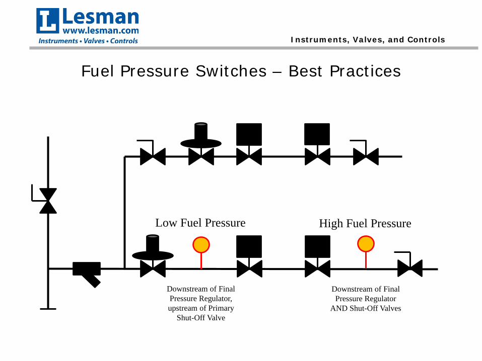
Low Fuel Pressure High Fuel Pressure
Downstream of Final Pressure Regulator, upstream of Primary
Shut-Off Valve
Downstream of Final Pressure Regulator
AND Shut-Off Valves
Instruments, Valves, and Controls
Fuel Pressure Switches – Best Practices
• From experience, it is my personal preference to use a manual reset fuel pressure switch unless:–Fuel Train is difficult to access–Burner Management System has first
out annunciation
Instruments, Valves, and Controls
Fuel Pressure Switches – Best Practices
• For setting the fuel pressure switches, I recommend the following:– With the burner at LOW fire, decrease the setting on
the HIGH fuel pressure switch until it trips. Note the setting, and adjust the switch to 20% above that setting.
• EX: If the switch tripped at 10”wc, set the switch for 12”wc
– With the burner at HIGH fire, increase the setting on the LOW Fuel pressure switch unti lit trips. Note the setting, and adjust the switch to 20% below that setting.
• EX: If the switch tripped at 10”wc, set the switch for 8”wc
Instruments, Valves, and Controls
Time Delays on Pressure Switches
• NFPA 86 8.2.8.2 The requirement in 8.2.8 shall not prohibit a time delay applied to the action of pressure-proving, flow-proving, or proof-of-closure safety switch as used in accordance with 8.8.1.3(3), where the following conditions exist:
Instruments, Valves, and Controls
Time Delays on Pressure Switches (cont.)
– (1) There is an operational need demonstrated for the time delay.
– (2) The use of a time delay is approved.– (3) The time delay feature is not adjustable beyond
5 seconds.– (4) A single time delay does not serve more than
one pressure-proving or flow-proving safety device.– (5) The time from an abnormal pressure or flow
condition until the holding medium is removed from the safety shutoff valves does not exceed 5 seconds.
• Snubbers are allowed, as long as it meets the above criteria (cannot delay for more than 5 seconds).
Instruments, Valves, and Controls
Safety Shutoff Valves
Instruments, Valves, and Controls
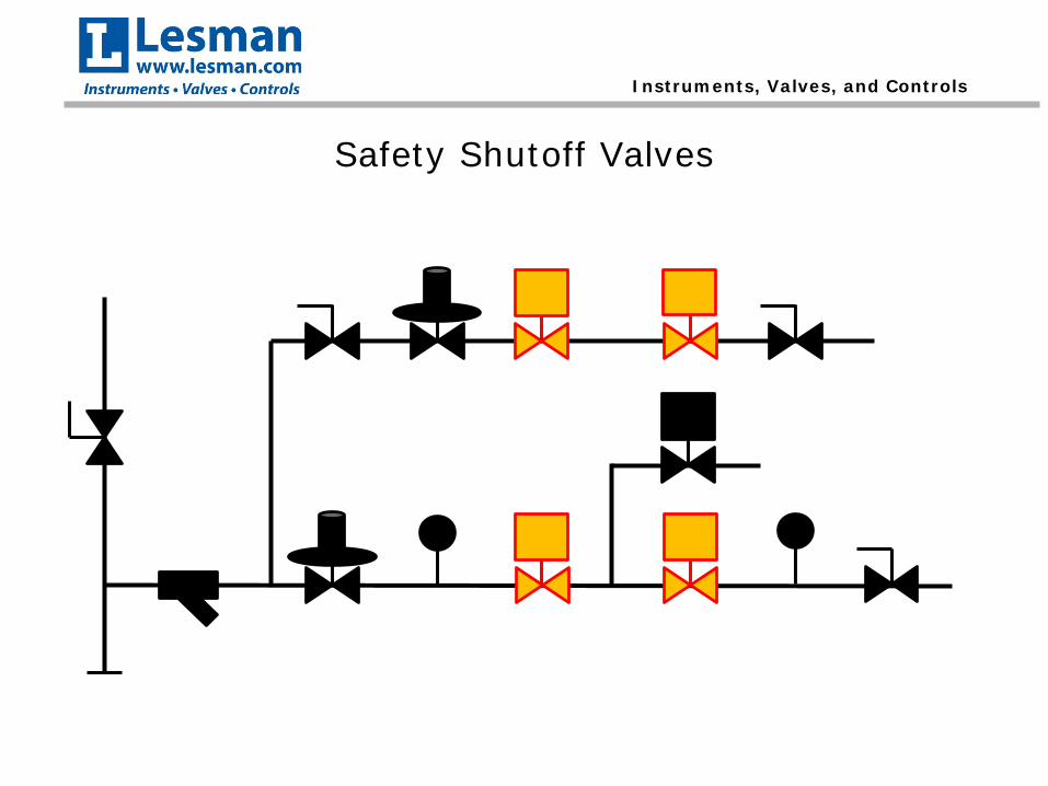
Safety Shutoff Valves
• Most critical component in any fuel train.
• NFPA 86 3.3.78.2 Safety Shutoff Valve A normally closed valve installed in the piping that closes automatically to shut off the fuel, atmosphere gas, or oxygen in the event of abnormal conditions during shutdown.
Instruments, Valves, and Controls
NFPA 86 Requirements for Safety Shutoff Valves
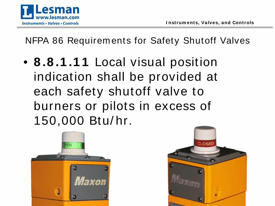
• 8.8.1.11 Local visual position indication shall be provided at each safety shutoff valve to burners or pilots in excess of 150,000 Btu/hr.
Instruments, Valves, and Controls
NFPA 86 Requirements for Safety Shutoff Valves
• 8.8.2.2 Where a safety shutoff valve is required to be proved closed, the following shall apply:
• (A) A proved closed condition shall be accomplished by either of the following means– (1) A proof-of-closure switch incorporated in a listed
safety shutoff valve assembly in accordance with the terms of the listing
– (2) A valve proving system• (B) Auxiliary and closed position indicator
switches shall not satisfy the proved closed requirement of 8.8.2.2 (A)
Instruments, Valves, and Controls
NFPA 86 Requirements for Safety Shutoff Valves
• When is a safety valve required to be proven closed?
• When the capacity of the main or pilot exceeds 400,000 Btu/hr, at least one of the safety shutoff valves between each burner and the fuel supply shall be proved closed and interlocked with the pre-ignition purge interval.
Instruments, Valves, and Controls
NFPA 86 Requirements for Safety Shutoff Valves
• NFPA 86 8.8.1.12 Safety shutoff valves shall meet one of the following requirements:– (1) The safety shutoff valve shall close in 1
second or less upon being de-energized.– (2) Where safety shutoff valve closure time
exceeds 1 second, the combined time for safety shutoff valve closure and flame failure response shall not exceed 5 seconds.
Instruments, Valves, and Controls
Best Practices for Safety Shutoff Valves
• To cascade or not to cascade?– Cascading shutoff valves energizes valves
individually in sequence instead of energizing them all at the same time.
– This can help in applications where introducing the fuel to quickly into the system causes issues with the regulators, pressure switches, or achieving a reliable light-off.
– Also reduces the current draw through the burner management system.
• Cascading shutoff valves increases the time it takes the fuel to reach the burner, cutting into your pilot or main flame establishment period.
Instruments, Valves, and Controls
Double Block / Block and Bleed
Instruments, Valves, and Controls
Valve Proving System
• NFPA 86 3.3.79 Valve Proving System A system used to check the closure of safety shutoff valves by detecting leakage.
• Replaces vent valve in block and bleed arrangement with a valve proving pressure switch
• Valves are cycled individually either prior to or after a run cycle to test the valves for leakage (by means of pressure).
• Does not replace annual valve seat leakage testing, this still needs to be done.
Instruments, Valves, and Controls
Run Mode – Pilot Off, Main On
Instruments, Valves, and Controls
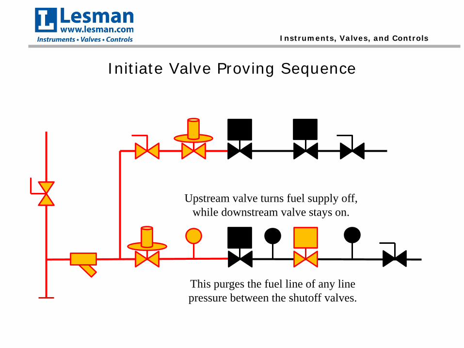
Initiate Valve Proving Sequence
Upstream valve turns fuel supply off, while downstream valve stays on.
This purges the fuel line of any line pressure between the shutoff valves.
Instruments, Valves, and Controls
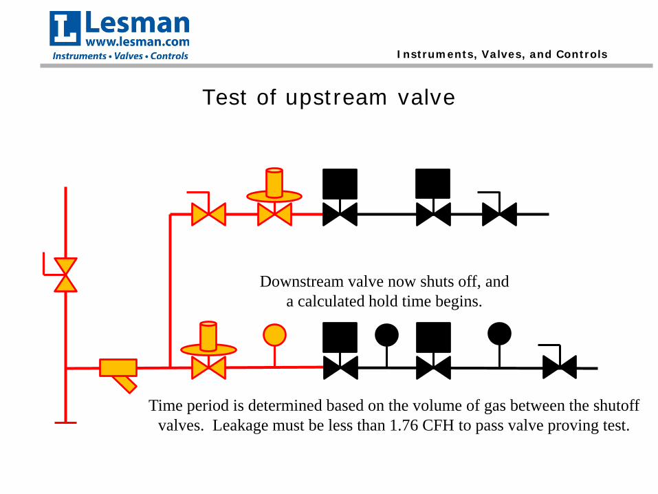
Test of upstream valve
Downstream valve now shuts off, and a calculated hold time begins.
Time period is determined based on the volume of gas between the shutoff valves. Leakage must be less than 1.76 CFH to pass valve proving test.
Instruments, Valves, and Controls
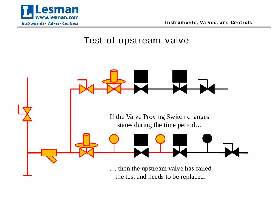
Test of upstream valve
If the Valve Proving Switch changes states during the time period…
… then the upstream valve has failed the test and needs to be replaced.
Instruments, Valves, and Controls
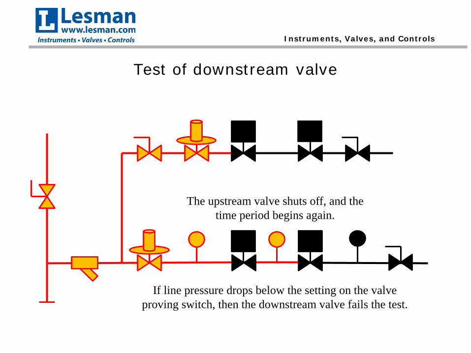
Test of downstream valve
After the upstream valve is tested, it is energized to bring line pressure between the valves.
Instruments, Valves, and Controls
Test of downstream valve
The upstream valve shuts off, and the time period begins again.
If line pressure drops below the setting on the valve proving switch, then the downstream valve fails the test.
Instruments, Valves, and Controls
Benefits of Valve Proving System
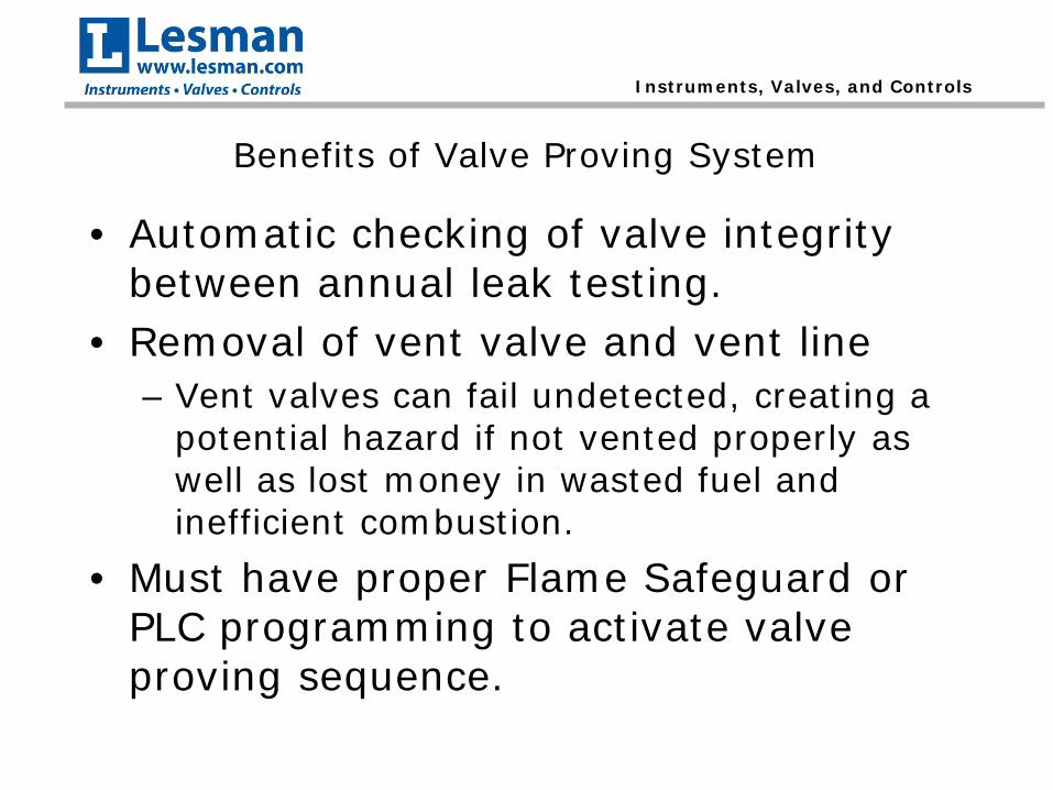
• Automatic checking of valve integrity between annual leak testing.
• Removal of vent valve and vent line– Vent valves can fail undetected, creating a
potential hazard if not vented properly as well as lost money in wasted fuel and inefficient combustion.
• Must have proper Flame Safeguard or PLC programming to activate valve proving sequence.
Instruments, Valves, and Controls
Leak Testing of Shutoff Valves
• Valve seat leak testing needs to be preformed per the manufacturer’s requirements (typically annually).
• NFPA 86 8.8.2.3 Means for testing all fuel gas shutoff valves for valve seat leakage shall be installed.– If the valve body does not have built-in test
ports, then test ports need to be installed in the piping.
Instruments, Valves, and Controls
Typical Valve Seat Leakage Test Procedure
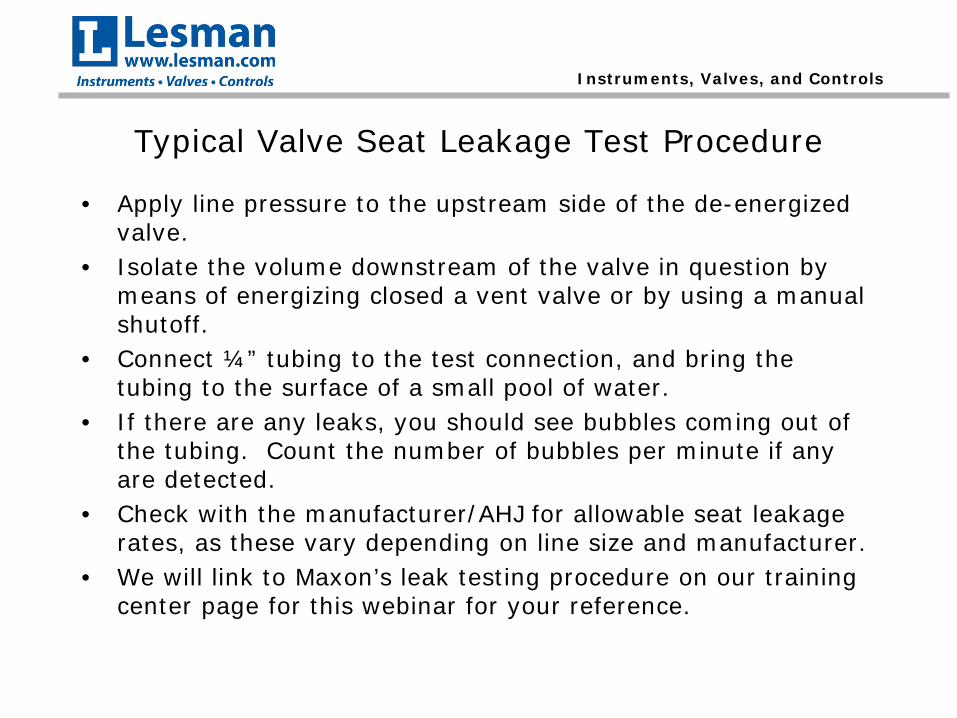
• Apply line pressure to the upstream side of the de-energized valve.
• Isolate the volume downstream of the valve in question by means of energizing closed a vent valve or by using a manual shutoff.
• Connect ¼” tubing to the test connection, and bring the tubing to the surface of a small pool of water.
• If there are any leaks, you should see bubbles coming out of the tubing. Count the number of bubbles per minute if any are detected.
• Check with the manufacturer/AHJ for allowable seat leakage rates, as these vary depending on line size and manufacturer.
• We will link to Maxon’s leak testing procedure on our training center page for this webinar for your reference.
Instruments, Valves, and Controls
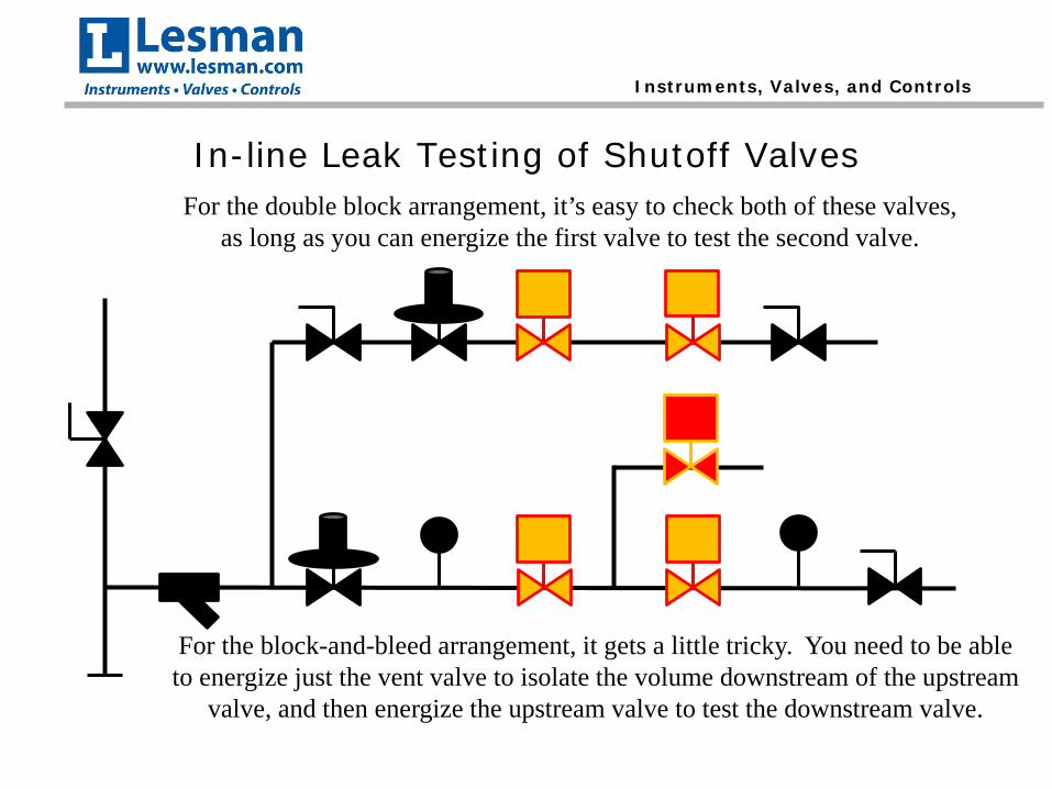
In-line Leak Testing of Shutoff ValvesFor the double block arrangement, it’s easy to check both of these valves,
as long as you can energize the first valve to test the second valve.
For the block-and-bleed arrangement, it gets a little tricky. You need to be able to energize just the vent valve to isolate the volume downstream of the upstream
valve, and then energize the upstream valve to test the downstream valve.
Instruments, Valves, and Controls
In-line Leak Testing of Shutoff Valves
Some people prefer to add manual isolation valves downstream of each valve to assist with the leak testing procedure. Just make
sure you don’t add a manual shutoff valve to the vent line!
Valve Technical Data
w w w . m a x o n c o r p . c o mcombustion systems for industry
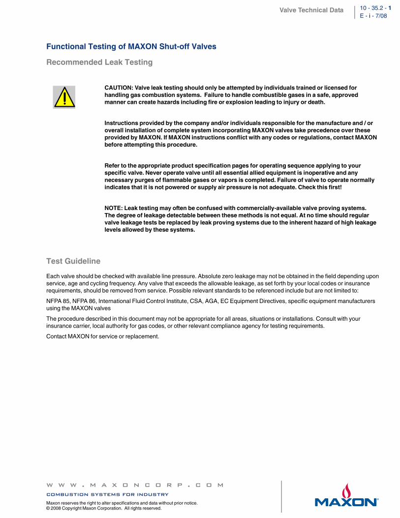
Each valve should be checked with available line pressure. Absolute zero leakage may not be obtained in the field depending upon service, age and cycling frequency. Any valve that exceeds the allowable leakage, as set forth by your local codes or insurance requirements, should be removed from service. Possible relevant standards to be referenced include but are not limited to:
NFPA 85, NFPA 86, International Fluid Control Institute, CSA, AGA, EC Equipment Directives, specific equipment manufacturers using the MAXON valves
The procedure described in this document may not be appropriate for all areas, situations or installations. Consult with your insurance carrier, local authority for gas codes, or other relevant compliance agency for testing requirements.
Contact MAXON for service or replacement.
CAUTION: Valve leak testing should only be attempted by individuals trained or licensed for handling gas combustion systems. Failure to handle combustible gases in a safe, approved manner can create hazards including fire or explosion leading to injury or death.
Instructions provided by the company and/or individuals responsible for the manufacture and / or overall installation of complete system incorporating MAXON valves take precedence over these provided by MAXON. If MAXON instructions conflict with any codes or regulations, contact MAXON before attempting this procedure.
Refer to the appropriate product specification pages for operating sequence applying to your specific valve. Never operate valve until all essential allied equipment is inoperative and any necessary purges of flammable gases or vapors is completed. Failure of valve to operate normally indicates that it is not powered or supply air pressure is not adequate. Check this first!
NOTE: Leak testing may often be confused with commercially-available valve proving systems. The degree of leakage detectable between these methods is not equal. At no time should regular valve leakage tests be replaced by leak proving systems due to the inherent hazard of high leakage levels allowed by these systems.
Valve Technical Data
w w w . m a x o n c o r p . c o mcombustion systems for industryMaxon reserves the right to alter specifications and data without prior notice.
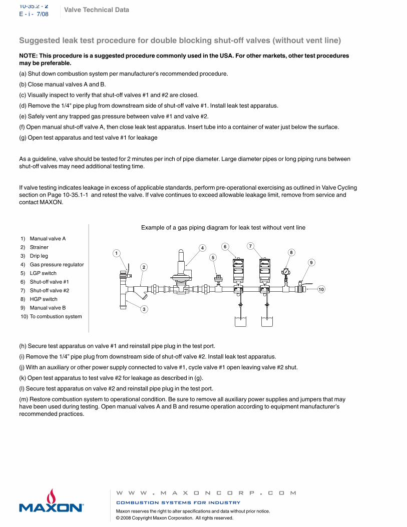
Suggested leak test procedure for double blocking shut-off valves (without vent line)
NOTE: This procedure is a suggested procedure commonly used in the USA. For other markets, other test procedures may be preferable.
(a) Shut down combustion system per manufacturer's recommended procedure.
(b) Close manual valves A and B.
(c) Visually inspect to verify that shut-off valves #1 and #2 are closed.
(d) Remove the 1/4" pipe plug from downstream side of shut-off valve #1. Install leak test apparatus.
(e) Safely vent any trapped gas pressure between valve #1 and valve #2.
(f) Open manual shut-off valve A, then close leak test apparatus. Insert tube into a container of water just below the surface.
(g) Open test apparatus and test valve #1 for leakage
As a guideline, valve should be tested for 2 minutes per inch of pipe diameter. Large diameter pipes or long piping runs between shut-off valves may need additional testing time.
If valve testing indicates leakage in excess of applicable standards, perform pre-operational exercising as outlined in Valve Cycling section on Page 10-35.1-1 and retest the valve. If valve continues to exceed allowable leakage limit, remove from service and contact MAXON.
(h) Secure test apparatus on valve #1 and reinstall pipe plug in the test port.
(i) Remove the 1/4” pipe plug from downstream side of shut-off valve #2. Install leak test apparatus.
(j) With an auxiliary or other power supply connected to valve #1, cycle valve #1 open leaving valve #2 shut.
(k) Open test apparatus to test valve #2 for leakage as described in (g).
(l) Secure test apparatus on valve #2 and reinstall pipe plug in the test port.
(m) Restore combustion system to operational condition. Be sure to remove all auxiliary power supplies and jumpers that may have been used during testing. Open manual valves A and B and resume operation according to equipment manufacturer’s recommended practices.
1) Manual valve A
2) Strainer
3) Drip leg
4) Gas pressure regulator
5) LGP switch
6) Shut-off valve #1
7) Shut-off valve #2
8) HGP switch
9) Manual valve B
10) To combustion system
Example of a gas piping diagram for leak test without vent line
10
1
2
3
4
5
768
9
Valve Technical Data
w w w . m a x o n c o r p . c o mcombustion systems for industry
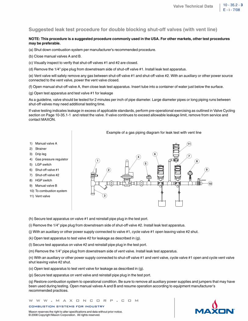
Suggested leak test procedure for double blocking shut-off valves (with vent line)
NOTE: This procedure is a suggested procedure commonly used in the USA. For other markets, other test procedures may be preferable.
(a) Shut down combustion system per manufacturer's recommended procedure.
(b) Close manual valves A and B.
(c) Visually inspect to verify that shut-off valves #1 and #2 are closed.
(d) Remove the 1/4" pipe plug from downstream side of shut-off valve #1. Install leak test apparatus.
(e) Vent valve will safely remove any gas between shut-off valve #1 and shut-off valve #2. With an auxiliary or other power source connected to the vent valve, power the vent valve closed.
(f) Open manual shut-off valve A, then close leak test apparatus. Insert tube into a container of water just below the surface.
(g) Open test apparatus and test valve #1 for leakage
As a guideline, valve should be tested for 2 minutes per inch of pipe diameter. Large diameter pipes or long piping runs between shut-off valves may need additional testing time.
If valve testing indicates leakage in excess of applicable standards, perform pre-operational exercising as outlined in Valve Cycling section on Page 10-35.1-1 and retest the valve. If valve continues to exceed allowable leakage limit, remove from service and contact MAXON.
(h) Secure test apparatus on valve #1 and reinstall pipe plug in the test port.
(i) Remove the 1/4” pipe plug from downstream side of shut-off valve #2. Install leak test apparatus.
(j) With an auxiliary or other power supply connected to valve #1, cycle valve #1 open leaving valve #2 shut.
(k) Open test apparatus to test valve #2 for leakage as described in (g).
(l) Secure test apparatus on valve #2 and reinstall pipe plug in the test port.
(m) Remove the 1/4” pipe plug from downstream side of vent valve. Install leak test apparatus.
(n) With an auxiliary or other power supply connected to shut-off valve #1 and vent valve, cycle valve #1 open and cycle vent valve shut leaving valve #2 shut.
(o) Open test apparatus to test vent valve for leakage as described in (g).
(p) Secure test apparatus on vent valve and reinstall pipe plug in the test port.
(q) Restore combustion system to operational condition. Be sure to remove all auxiliary power supplies and jumpers that may have been used during testing. Open manual valves A and B and resume operation according to equipment manufacturer’s recommended practices.
1) Manual valve A
2) Strainer
3) Drip leg
4) Gas pressure regulator
5) LGP switch
6) Shut-off valve #1
7) Shut-off valve #2
8) HGP switch
9) Manual valve B
10) To combustion system
11) Vent valve
Example of a gas piping diagram for leak test with vent line
1
2
3
4
5
67
8
10
9
11
Instruments, Valves, and Controls
Thank You for Your Time
Any Questions???
Instruments, Valves, and Controls
Get Social with Lesman
• Our Website– www.lesman.com
• Dan’s Tips blog– blog.lesman.com
• Follow us on LinkedIn– www.linkedin.com/company/
lesman-instrument-company• Follow us on Twitter
– @Lesman_Inst• Check Out our YouTube Channel
– www.youtube.com/user/LesmanInstrumentCo
Instruments, Valves, and Controls
Selecting The Right Radar AntennaThursday, March 17 9am CST
Upcoming Webinar:
Featured SpeakerMark Klee
Senior Application Engineer,Level and Weighing ProductsSiemens


![MAXON APX Specifications - Lesman · LP burner (Low Pressure drillings). Actual pressure differential at burner gas inlet is 5 % higher. [6] Fresh air firing.](https://static.documents.pub/doc/80x56/5d3fdb8188c993860c8df8a8/maxon-apx-specifications-lp-burner-low-pressure-drillings-actual-pressure.jpg)


