136
Part No. P0606013 02 Business Communications Manager (version 3.5 software) DECT Installation and Maintenance Guide

Part No. P0606013 02
Business Communications Manager (version 3.5 software)
DECT Installation and Maintenance Guide
2
Copyright © 2003 Nortel Networks
All rights reserved. September, 2003.
The information in this document is subject to change without notice. The statements, configurations, technical data, and recommendations in this document are believed to be accurate and reliable, but are presented without express or implied warranty. Users must take full responsibility for their applications of any products specified in this document. The information in this document is proprietary to Nortel Networks NA Inc.
Trademarks
NORTEL NETWORKS is a trademark of Nortel Networks.
Microsoft, MS, MS-DOS, Windows, and Windows NT are registered trademarks of Microsoft Corporation.
All other trademarks and registered trademarks are the property of their respective owners.
DECT regulatory information
This is a class A product. In a domestic environment this product may cause radio interference in which case the user may be required to take adequate measures.
Hereby, Nortel Networks declares that Enterprise Edge/ Business Communications Manager Model No. NT7B10xxxx, is in compliance with the essential requirements and other relevant provisions of Directive 1999/5/EC.
The C4010/C4020 handset is in compliance with Council Recommendation 1999/519/EC.
The DECT Base Station shall be cabled from host PBX controller card via individually screened paired cable.
The DECT standard is an integrated solution for cordless communication services based upon these ETSI specifications:
• ETS 300-175: Digital Enhanced Cordless Telephone Common Interface
• ETS 300-176: Digital Enhanced Cordless Telephone approval test specification
• ETS 300-444: Digital Enhanced Cordless Telephone General Access Profile
The DECT module provides an interface to the Business Communications Manager for cordless handsets through a radio link with a base station connected directly to the DECT module. The interface is created by linking four BRI loops and a Mercator C8 PBX through a BRI within the module circuitry.
The CE Marking on this equipment indicates compliance with the following:This device conforms to Directive 1999/5/EC on Radio Equipment and Telecommunications Terminal Equipment as adopted by the European Parliament And Of The Council.
P0606013 02

3
Electromagnetic compatibility
DECT standard complies with the following safety and electromagnetic compatibility recommendations:
• ETS 300329:Radio Equipment Systems; Electromagnetic Compatibility for Digital Enhanced Cordless Telephone.
• EN 60950: Safety of Information Technology Equipment.
• EN 55022: Electromagnetic Compatibility for Information Technology Equipment.
DECT Installation and Maintenance Guide

4
P0606013 02
5
Contents
DECT regulatory information . . . . . . . . . . . . . . . . . . . . . . . . . . . . . . . . . . . . . . . . . . . . . 2
Electromagnetic compatibility . . . . . . . . . . . . . . . . . . . . . . . . . . . . . . . . . . . . . . . . . 3
Preface . . . . . . . . . . . . . . . . . . . . . . . . . . . . . . . . . . . . . . . . . . . . . . . . . . . . . . 13
Symbols Used in this Guide . . . . . . . . . . . . . . . . . . . . . . . . . . . . . . . . . . . . . . . . . . . . 13
Text Conventions Used in This Guide . . . . . . . . . . . . . . . . . . . . . . . . . . . . . . . . . . . . . 14
Acronyms . . . . . . . . . . . . . . . . . . . . . . . . . . . . . . . . . . . . . . . . . . . . . . . . . . . . . . . . . . . 14
Related Publications . . . . . . . . . . . . . . . . . . . . . . . . . . . . . . . . . . . . . . . . . . . . . . . . . . 15
Chapter 1DECT system overview and requirements . . . . . . . . . . . . . . . . . . . . . . . . . 17
DECT features . . . . . . . . . . . . . . . . . . . . . . . . . . . . . . . . . . . . . . . . . . . . . . . . . . . . . . . 19
Business Communications Manager features . . . . . . . . . . . . . . . . . . . . . . . . . . . . 19Handset features . . . . . . . . . . . . . . . . . . . . . . . . . . . . . . . . . . . . . . . . . . . . . . . . . . 20
Setup process overview . . . . . . . . . . . . . . . . . . . . . . . . . . . . . . . . . . . . . . . . . . . . . . . . 21
DECT base station deployment planning . . . . . . . . . . . . . . . . . . . . . . . . . . . . . . . . . . 22
DECT radio base station . . . . . . . . . . . . . . . . . . . . . . . . . . . . . . . . . . . . . . . . . . . . . . . 22
External antennas . . . . . . . . . . . . . . . . . . . . . . . . . . . . . . . . . . . . . . . . . . . . . . . . . 23
Specifications for DECT radio base stations . . . . . . . . . . . . . . . . . . . . . . . . . . . . . 25
Base station notes: . . . . . . . . . . . . . . . . . . . . . . . . . . . . . . . . . . . . . . . . . . . . . . . . 26
Climatic conditions . . . . . . . . . . . . . . . . . . . . . . . . . . . . . . . . . . . . . . . . . . . . . 26
Power supply . . . . . . . . . . . . . . . . . . . . . . . . . . . . . . . . . . . . . . . . . . . . . . . . . 26
Description of the connection . . . . . . . . . . . . . . . . . . . . . . . . . . . . . . . . . . . . . . . . 26
DECT cordless handsets . . . . . . . . . . . . . . . . . . . . . . . . . . . . . . . . . . . . . . . . . . . . . . . 27
Site configurations . . . . . . . . . . . . . . . . . . . . . . . . . . . . . . . . . . . . . . . . . . . . . . . . . . . . 27
DECT call paths . . . . . . . . . . . . . . . . . . . . . . . . . . . . . . . . . . . . . . . . . . . . . . . . . . . . . . 27
DECT programming overview . . . . . . . . . . . . . . . . . . . . . . . . . . . . . . . . . . . . . . . . . . . 28
DECT interface commands . . . . . . . . . . . . . . . . . . . . . . . . . . . . . . . . . . . . . . . . . . 28
Numbering plan syntax . . . . . . . . . . . . . . . . . . . . . . . . . . . . . . . . . . . . . . . . . . . . . 29
Business Communications Manager requirements . . . . . . . . . . . . . . . . . . . . . . . . . . . 29
Checking the System Region . . . . . . . . . . . . . . . . . . . . . . . . . . . . . . . . . . . . . . . . . . . 30
Chapter 2Installing the DECT media bay module . . . . . . . . . . . . . . . . . . . . . . . . . . . . 31
Setting the DIP switches . . . . . . . . . . . . . . . . . . . . . . . . . . . . . . . . . . . . . . . . . . . . . . . 32
Installing the DECT module . . . . . . . . . . . . . . . . . . . . . . . . . . . . . . . . . . . . . . . . . . . . . 34
Restoring the system . . . . . . . . . . . . . . . . . . . . . . . . . . . . . . . . . . . . . . . . . . . . . . 35
Chapter 3Configuring the DECT module . . . . . . . . . . . . . . . . . . . . . . . . . . . . . . . . . . . 37
Process overview: Identify and configure the DECT Module . . . . . . . . . . . . . . . . . . . . 38
Confirming the DECT module . . . . . . . . . . . . . . . . . . . . . . . . . . . . . . . . . . . . . . . . . . . 39
DECT Installation and Maintenance Guide
6 Contents
Configuring the module for µ-law . . . . . . . . . . . . . . . . . . . . . . . . . . . . . . . . . . . . . . . . . 40
Before you start . . . . . . . . . . . . . . . . . . . . . . . . . . . . . . . . . . . . . . . . . . . . . . . . . . . 40
Setting up the DECT file for upload . . . . . . . . . . . . . . . . . . . . . . . . . . . . . . . . . . . . 41
Resetting the module to default values . . . . . . . . . . . . . . . . . . . . . . . . . . . . . . . . . 42
Checking the Unified Manager handset DNs . . . . . . . . . . . . . . . . . . . . . . . . . . . . . . . . 43
Setting up the handsets . . . . . . . . . . . . . . . . . . . . . . . . . . . . . . . . . . . . . . . . . . . . . . . . 44
Stand-alone handset . . . . . . . . . . . . . . . . . . . . . . . . . . . . . . . . . . . . . . . . . . . . . . . 45
Assigning routes or lines . . . . . . . . . . . . . . . . . . . . . . . . . . . . . . . . . . . . . . . . 45
Assigning target lines . . . . . . . . . . . . . . . . . . . . . . . . . . . . . . . . . . . . . . . . . . . 45
Assigning handsets to fixed telephone DNs . . . . . . . . . . . . . . . . . . . . . . . . . . . . . 46
Handset feature programming . . . . . . . . . . . . . . . . . . . . . . . . . . . . . . . . . . . . . . . . 46
About the DECT Wizards . . . . . . . . . . . . . . . . . . . . . . . . . . . . . . . . . . . . . . . . . . . . . . 47
Understanding the DECT Configuration Wizard . . . . . . . . . . . . . . . . . . . . . . . . . . 47
Before you start . . . . . . . . . . . . . . . . . . . . . . . . . . . . . . . . . . . . . . . . . . . . . . . 47
Using the Configuration Wizard . . . . . . . . . . . . . . . . . . . . . . . . . . . . . . . . . . . . . . 49
Setting up the module Time Synch . . . . . . . . . . . . . . . . . . . . . . . . . . . . . . . . . . . . 50
Chapter 4Installing the DECT base station . . . . . . . . . . . . . . . . . . . . . . . . . . . . . . . . . 53
Installing base station hardware . . . . . . . . . . . . . . . . . . . . . . . . . . . . . . . . . . . . . . . . . 53
Special considerations . . . . . . . . . . . . . . . . . . . . . . . . . . . . . . . . . . . . . . . . . . . . . 53
Installing the base station on the wall . . . . . . . . . . . . . . . . . . . . . . . . . . . . . . . . . . 54
Base station connections . . . . . . . . . . . . . . . . . . . . . . . . . . . . . . . . . . . . . . . . . . . 55
Connecting the base station to the system . . . . . . . . . . . . . . . . . . . . . . . . . . . . . . . . . 56
Checking the base station wiring . . . . . . . . . . . . . . . . . . . . . . . . . . . . . . . . . . . . . 56
Attaching the base station to the module . . . . . . . . . . . . . . . . . . . . . . . . . . . . . . . 57
Base station antennas . . . . . . . . . . . . . . . . . . . . . . . . . . . . . . . . . . . . . . . . . . . . . . . . . 58
Attaching external antennas to the base station . . . . . . . . . . . . . . . . . . . . . . . . . . 59
Chapter 5Subscribing DECT cordless handsets . . . . . . . . . . . . . . . . . . . . . . . . . . . . . 61
Process map: subscribing the handsets . . . . . . . . . . . . . . . . . . . . . . . . . . . . . . . . . . . 62
Base station recording status . . . . . . . . . . . . . . . . . . . . . . . . . . . . . . . . . . . . . . . . . . . 63
DECT Mobile Recording (Handset Subscription) Wizard . . . . . . . . . . . . . . . . . . . 63
Before you start . . . . . . . . . . . . . . . . . . . . . . . . . . . . . . . . . . . . . . . . . . . . . . . . . . . 63
Filling out the Mobile Recording (Handset Subscription) Wizard . . . . . . . . . . . . . 64
Turning off mobile recording . . . . . . . . . . . . . . . . . . . . . . . . . . . . . . . . . . . . . . 64
Subscribing DECT cordless handsets . . . . . . . . . . . . . . . . . . . . . . . . . . . . . . . . . . . . . 65
Handset buttons . . . . . . . . . . . . . . . . . . . . . . . . . . . . . . . . . . . . . . . . . . . . . . . . . . 65
Subscribing a handset . . . . . . . . . . . . . . . . . . . . . . . . . . . . . . . . . . . . . . . . . . . . . . 66
Resetting the base station . . . . . . . . . . . . . . . . . . . . . . . . . . . . . . . . . . . . . . . . . . . 67
Checking handset status . . . . . . . . . . . . . . . . . . . . . . . . . . . . . . . . . . . . . . . . . . . . 68
Confirming base station readiness . . . . . . . . . . . . . . . . . . . . . . . . . . . . . . . . . . . . 69
P0606013 02

Contents 7
Setup test . . . . . . . . . . . . . . . . . . . . . . . . . . . . . . . . . . . . . . . . . . . . . . . . . . . . . . . 71
Handset system features . . . . . . . . . . . . . . . . . . . . . . . . . . . . . . . . . . . . . . . . . . . . . . . 71
Hunt groups . . . . . . . . . . . . . . . . . . . . . . . . . . . . . . . . . . . . . . . . . . . . . . . . . . . . . . 72
Message Waiting Indicator (MWI) . . . . . . . . . . . . . . . . . . . . . . . . . . . . . . . . . . . . . 72
Programming the MWI lamp button . . . . . . . . . . . . . . . . . . . . . . . . . . . . . . . . 73
Twinning features . . . . . . . . . . . . . . . . . . . . . . . . . . . . . . . . . . . . . . . . . . . . . . . . . 73
CallPilot programming . . . . . . . . . . . . . . . . . . . . . . . . . . . . . . . . . . . . . . . . . . . . . . 73
Auto-answer issues . . . . . . . . . . . . . . . . . . . . . . . . . . . . . . . . . . . . . . . . . . . . . . . . 73
Receiving a page . . . . . . . . . . . . . . . . . . . . . . . . . . . . . . . . . . . . . . . . . . . . . . . . . 74
Roaming . . . . . . . . . . . . . . . . . . . . . . . . . . . . . . . . . . . . . . . . . . . . . . . . . . . . . . . . 74
Roaming on outgoing calls . . . . . . . . . . . . . . . . . . . . . . . . . . . . . . . . . . . . . . . 75
Direct Inward Roaming . . . . . . . . . . . . . . . . . . . . . . . . . . . . . . . . . . . . . . . . . . 75
Chapter 6Programming DECT module defaults . . . . . . . . . . . . . . . . . . . . . . . . . . . . . 77
Accessing the Maintenance Console . . . . . . . . . . . . . . . . . . . . . . . . . . . . . . . . . . . . . 78
System Management . . . . . . . . . . . . . . . . . . . . . . . . . . . . . . . . . . . . . . . . . . . . . . . . . . 79
DECT and handset passwords . . . . . . . . . . . . . . . . . . . . . . . . . . . . . . . . . . . . . . . 79
Language Management . . . . . . . . . . . . . . . . . . . . . . . . . . . . . . . . . . . . . . . . . . . . 80
Card Management . . . . . . . . . . . . . . . . . . . . . . . . . . . . . . . . . . . . . . . . . . . . . . . . 81
External antenna settings . . . . . . . . . . . . . . . . . . . . . . . . . . . . . . . . . . . . . . . . . . . . . . 81
Chapter 7Programming numbering plans and base stations . . . . . . . . . . . . . . . . . . 83
Planning your DECT settings . . . . . . . . . . . . . . . . . . . . . . . . . . . . . . . . . . . . . . . . . . . . 84
Setting DECT PARI values . . . . . . . . . . . . . . . . . . . . . . . . . . . . . . . . . . . . . . . . . . . . . 85
Telephony Management . . . . . . . . . . . . . . . . . . . . . . . . . . . . . . . . . . . . . . . . . . . . . . . 86
Outgoing Numbering Plan . . . . . . . . . . . . . . . . . . . . . . . . . . . . . . . . . . . . . . . . . . . . . . 87
User Numbering Plan . . . . . . . . . . . . . . . . . . . . . . . . . . . . . . . . . . . . . . . . . . . . . . 88
Incoming Call Numbering Plan . . . . . . . . . . . . . . . . . . . . . . . . . . . . . . . . . . . . . . . 89
Wireless Management . . . . . . . . . . . . . . . . . . . . . . . . . . . . . . . . . . . . . . . . . . . . . . . . . 91
Cell names . . . . . . . . . . . . . . . . . . . . . . . . . . . . . . . . . . . . . . . . . . . . . . . . . . . . . . 91
Managing Logical Trunks . . . . . . . . . . . . . . . . . . . . . . . . . . . . . . . . . . . . . . . . . . . 92
Chapter 8Programming DECT handset records . . . . . . . . . . . . . . . . . . . . . . . . . . . . . 93
Confirming the DECT settings . . . . . . . . . . . . . . . . . . . . . . . . . . . . . . . . . . . . . . . . . . . 93
Identifying base stations . . . . . . . . . . . . . . . . . . . . . . . . . . . . . . . . . . . . . . . . . . . . 94
Mobile Management . . . . . . . . . . . . . . . . . . . . . . . . . . . . . . . . . . . . . . . . . . . . . . . . . . 96
Listing mobiles (handsets) . . . . . . . . . . . . . . . . . . . . . . . . . . . . . . . . . . . . . . . . . . 97
Identifying handsets . . . . . . . . . . . . . . . . . . . . . . . . . . . . . . . . . . . . . . . . . . . . . . . 98
Removing handsets . . . . . . . . . . . . . . . . . . . . . . . . . . . . . . . . . . . . . . . . . . . . . . . 98
Confirming the handset extension record . . . . . . . . . . . . . . . . . . . . . . . . . . . . . . . 99
DECT Installation and Maintenance Guide

8 Contents
Chapter 9Maintaining and upgrading DECT software. . . . . . . . . . . . . . . . . . . . . . . . 103
Accessing the BRU screen, Unified Manager menu . . . . . . . . . . . . . . . . . . . . . . . . . 103
Accessing the BRU screen, DECT Tools menu . . . . . . . . . . . . . . . . . . . . . . . . . . . . . 104
Backup and Restore DECT module data . . . . . . . . . . . . . . . . . . . . . . . . . . . . . . . . . . 105
Backing up DECT data . . . . . . . . . . . . . . . . . . . . . . . . . . . . . . . . . . . . . . . . . . . . 105
Restoring DECT data . . . . . . . . . . . . . . . . . . . . . . . . . . . . . . . . . . . . . . . . . . . . . 107
Viewing the backup/restore schedule . . . . . . . . . . . . . . . . . . . . . . . . . . . . . . . . . 108
Chapter 10Troubleshooting and Alarm Monitoring. . . . . . . . . . . . . . . . . . . . . . . . . . . 109
Radio base station fault on startup . . . . . . . . . . . . . . . . . . . . . . . . . . . . . . . . . . . . . . 109
Business Communications Manager application control . . . . . . . . . . . . . . . . . . . . . . 109
Viewing and changing the Maintenance Console status . . . . . . . . . . . . . . . . . . . . . . 111
Viewing and changing the DECT Alarm Monitor status . . . . . . . . . . . . . . . . . . . . . . . 112
Viewing alarms . . . . . . . . . . . . . . . . . . . . . . . . . . . . . . . . . . . . . . . . . . . . . . . . . . . . . 113
Base station/handset troubleshooting . . . . . . . . . . . . . . . . . . . . . . . . . . . . . . . . . . . . 113
Changing the TCPPort . . . . . . . . . . . . . . . . . . . . . . . . . . . . . . . . . . . . . . . . . . . . . . . 114
Monitoring the DECT module LEDs . . . . . . . . . . . . . . . . . . . . . . . . . . . . . . . . . . . . . 114
Determining module companding law setting . . . . . . . . . . . . . . . . . . . . . . . . . . . . . . 115
Appendix AQuick reference to DECT module programming. . . . . . . . . . . . . . . . . . . . 117
Appendix BCordless handset verification. . . . . . . . . . . . . . . . . . . . . . . . . . . . . . . . . . . 121
Determining handset subscription . . . . . . . . . . . . . . . . . . . . . . . . . . . . . . . . . . . . . . . 121
Unsubscribing the handset . . . . . . . . . . . . . . . . . . . . . . . . . . . . . . . . . . . . . . . . . . . . 122
Testing the handset . . . . . . . . . . . . . . . . . . . . . . . . . . . . . . . . . . . . . . . . . . . . . . . . . . 123
Test mode icons . . . . . . . . . . . . . . . . . . . . . . . . . . . . . . . . . . . . . . . . . . . . . . . . . 124
Glossary . . . . . . . . . . . . . . . . . . . . . . . . . . . . . . . . . . . . . . . . . . . . . . . . . . . . 125
Index . . . . . . . . . . . . . . . . . . . . . . . . . . . . . . . . . . . . . . . . . . . . . . . . . . . . . . . 129
P0606013 02

9
Figures
Figure 1 Integrated DECT service . . . . . . . . . . . . . . . . . . . . . . . . . . . . . . . . . . . . . 18
Figure 2 Setup process for the DECT system . . . . . . . . . . . . . . . . . . . . . . . . . . . . 21
Figure 3 Base station switches . . . . . . . . . . . . . . . . . . . . . . . . . . . . . . . . . . . . . . . . 23
Figure 4 Antenna configurations . . . . . . . . . . . . . . . . . . . . . . . . . . . . . . . . . . . . . . 24
Figure 5 Inside the DECT radio base station . . . . . . . . . . . . . . . . . . . . . . . . . . . . . 25
Figure 6 Process for installing the DECT module . . . . . . . . . . . . . . . . . . . . . . . . . . 31
Figure 7 Locating the DECT media bay module dip switches . . . . . . . . . . . . . . . . 32
Figure 8 Release tabs for the module bays . . . . . . . . . . . . . . . . . . . . . . . . . . . . . . 34
Figure 9 Front bezels replaced on units . . . . . . . . . . . . . . . . . . . . . . . . . . . . . . . . . 35
Figure 10 Locating the LEDs on the DECT module face . . . . . . . . . . . . . . . . . . . . . 36
Figure 11 Process for identifying and configuring the DECT module . . . . . . . . . . . . 38
Figure 12 Maintenance Tools menu . . . . . . . . . . . . . . . . . . . . . . . . . . . . . . . . . . . . . 41
Figure 13 Firmware upload . . . . . . . . . . . . . . . . . . . . . . . . . . . . . . . . . . . . . . . . . . . 42
Figure 14 Restore default firmware configuration . . . . . . . . . . . . . . . . . . . . . . . . . . . 42
Figure 15 Time synchronisation page . . . . . . . . . . . . . . . . . . . . . . . . . . . . . . . . . . . 50
Figure 16 Base station with cover pulled away . . . . . . . . . . . . . . . . . . . . . . . . . . . . . 54
Figure 17 RJ45 connectors on the media bay module . . . . . . . . . . . . . . . . . . . . . . . 57
Figure 18 Status LED on outside of base station . . . . . . . . . . . . . . . . . . . . . . . . . . . 58
Figure 19 Removing the internal antenna plate . . . . . . . . . . . . . . . . . . . . . . . . . . . . 59
Figure 20 Process for subscribing the cordless handsets . . . . . . . . . . . . . . . . . . . . 62
Figure 21 Define Radio Base Station ## DECT screen . . . . . . . . . . . . . . . . . . . . . . 68
Figure 22 Wireless Management Menu menu . . . . . . . . . . . . . . . . . . . . . . . . . . . . . 69
Figure 23 Wireless Resources Menu menu . . . . . . . . . . . . . . . . . . . . . . . . . . . . . . . 69
Figure 24 Base Station Selection menu . . . . . . . . . . . . . . . . . . . . . . . . . . . . . . . . . . 69
Figure 25 Define Radio Base Station XX DECT screen . . . . . . . . . . . . . . . . . . . . . . 70
Figure 26 DECT interface, system management . . . . . . . . . . . . . . . . . . . . . . . . . . . 77
Figure 27 Main DECT maintenance menu . . . . . . . . . . . . . . . . . . . . . . . . . . . . . . . . 78
Figure 28 System Management menu . . . . . . . . . . . . . . . . . . . . . . . . . . . . . . . . . . . 79
Figure 29 Password Management menu . . . . . . . . . . . . . . . . . . . . . . . . . . . . . . . . . 79
Figure 30 Parameter Management menu . . . . . . . . . . . . . . . . . . . . . . . . . . . . . . . . . 80
Figure 31 Wireless Resources menu . . . . . . . . . . . . . . . . . . . . . . . . . . . . . . . . . . . . 81
Figure 32 Base station screen . . . . . . . . . . . . . . . . . . . . . . . . . . . . . . . . . . . . . . . . . 82
Figure 33 DECT interface, trunk and cell management . . . . . . . . . . . . . . . . . . . . . . 83
Figure 34 Wireless Management menu . . . . . . . . . . . . . . . . . . . . . . . . . . . . . . . . . . 85
Figure 35 Wireless Topology menu . . . . . . . . . . . . . . . . . . . . . . . . . . . . . . . . . . . . . 85
Figure 36 DECT parameters screen . . . . . . . . . . . . . . . . . . . . . . . . . . . . . . . . . . . . 85
Figure 37 Telephony Management menu . . . . . . . . . . . . . . . . . . . . . . . . . . . . . . . . . 86
Figure 38 Numbering Plan menu . . . . . . . . . . . . . . . . . . . . . . . . . . . . . . . . . . . . . . . 87
Figure 39 User Numbering Plan menu . . . . . . . . . . . . . . . . . . . . . . . . . . . . . . . . . . . 87
Figure 40 DECT directory numbers . . . . . . . . . . . . . . . . . . . . . . . . . . . . . . . . . . . . . 88
DECT Installation and Maintenance Guide

10 Figures
Figure 41 Local Dialing List . . . . . . . . . . . . . . . . . . . . . . . . . . . . . . . . . . . . . . . . . . . 88
Figure 42 Incoming Call Numbering Plan menu . . . . . . . . . . . . . . . . . . . . . . . . . . . . 89
Figure 43 Incoming plan: Internal numb. . . . . . . . . . . . . . . . . . . . . . . . . . . . . . . . . . 90
Figure 44 Local Dialing List . . . . . . . . . . . . . . . . . . . . . . . . . . . . . . . . . . . . . . . . . . . 90
Figure 45 Wireless Management menu . . . . . . . . . . . . . . . . . . . . . . . . . . . . . . . . . . 91
Figure 46 Wireless Topology menu . . . . . . . . . . . . . . . . . . . . . . . . . . . . . . . . . . . . . 91
Figure 47 Wireless Resources menu . . . . . . . . . . . . . . . . . . . . . . . . . . . . . . . . . . . . 92
Figure 48 Telephony Management menu . . . . . . . . . . . . . . . . . . . . . . . . . . . . . . . . . 93
Figure 49 Wireless Management menu . . . . . . . . . . . . . . . . . . . . . . . . . . . . . . . . . . 93
Figure 50 Wireless Resources menu . . . . . . . . . . . . . . . . . . . . . . . . . . . . . . . . . . . . 94
Figure 51 Wireless Resources menu . . . . . . . . . . . . . . . . . . . . . . . . . . . . . . . . . . . . 94
Figure 52 Base station screen . . . . . . . . . . . . . . . . . . . . . . . . . . . . . . . . . . . . . . . . . 95
Figure 53 Wireless Mobiles menu . . . . . . . . . . . . . . . . . . . . . . . . . . . . . . . . . . . . . . 97
Figure 54 Display Mobiles screen . . . . . . . . . . . . . . . . . . . . . . . . . . . . . . . . . . . . . . 97
Figure 55 Create mobile record . . . . . . . . . . . . . . . . . . . . . . . . . . . . . . . . . . . . . . . . 98
Figure 56 Telephony Management menu . . . . . . . . . . . . . . . . . . . . . . . . . . . . . . . . . 99
Figure 57 Extension Data menu . . . . . . . . . . . . . . . . . . . . . . . . . . . . . . . . . . . . . . . . 99
Figure 58 Extension Characteristics menu . . . . . . . . . . . . . . . . . . . . . . . . . . . . . . . . 99
Figure 59 Handset record, page 1 . . . . . . . . . . . . . . . . . . . . . . . . . . . . . . . . . . . . . 100
Figure 60 Handset record, page 2 . . . . . . . . . . . . . . . . . . . . . . . . . . . . . . . . . . . . . 100
Figure 61 Handset record, page 3 . . . . . . . . . . . . . . . . . . . . . . . . . . . . . . . . . . . . . 101
Figure 62 Maintenance Tools menu . . . . . . . . . . . . . . . . . . . . . . . . . . . . . . . . . . . . 104
Figure 63 Backup and Restore Utility screen . . . . . . . . . . . . . . . . . . . . . . . . . . . . . 105
Figure 64 Scheduling a backup, one time . . . . . . . . . . . . . . . . . . . . . . . . . . . . . . . 106
Figure 65 Backup and Restore Utility screen . . . . . . . . . . . . . . . . . . . . . . . . . . . . . 107
Figure 66 Backup and Restore Utility, restore screen . . . . . . . . . . . . . . . . . . . . . . 107
Figure 67 Backup and Restore Utility screen . . . . . . . . . . . . . . . . . . . . . . . . . . . . . 108
Figure 68 Backup and Restore Utility, schedule screen . . . . . . . . . . . . . . . . . . . . . 108
Figure 69 Services list . . . . . . . . . . . . . . . . . . . . . . . . . . . . . . . . . . . . . . . . . . . . . . 109
Figure 70 Services list for DECT Maintenance Console . . . . . . . . . . . . . . . . . . . . 110
Figure 71 DECT Maintenance Console and Alarm Monitor . . . . . . . . . . . . . . . . . . 111
Figure 72 DECT Maintenance Console and Alarm Monitor . . . . . . . . . . . . . . . . . . 112
Figure 73 Alarm Banner . . . . . . . . . . . . . . . . . . . . . . . . . . . . . . . . . . . . . . . . . . . . . 113
P0606013 02

11
Tables
Table 1 Hardware components of the DECT system . . . . . . . . . . . . . . . . . . . . . . 18
Table 2 Parts of the DECT radio base station configurations . . . . . . . . . . . . . . . . 22
Table 3 Generated losses with extension cord added . . . . . . . . . . . . . . . . . . . . . 24
Table 4 DECT interface commands . . . . . . . . . . . . . . . . . . . . . . . . . . . . . . . . . . . 28
Table 5 Numbering plan syntax . . . . . . . . . . . . . . . . . . . . . . . . . . . . . . . . . . . . . . 29
Table 6 DECT switch settings . . . . . . . . . . . . . . . . . . . . . . . . . . . . . . . . . . . . . . . . 33
Table 7 Module settngs . . . . . . . . . . . . . . . . . . . . . . . . . . . . . . . . . . . . . . . . . . . . . 33
Table 8 Possible causes of interference . . . . . . . . . . . . . . . . . . . . . . . . . . . . . . . . 55
Table 9 Cable lengths and resistances . . . . . . . . . . . . . . . . . . . . . . . . . . . . . . . . . 56
Table 10 Base station LED conditions . . . . . . . . . . . . . . . . . . . . . . . . . . . . . . . . . . 58
Table 11 External antennas . . . . . . . . . . . . . . . . . . . . . . . . . . . . . . . . . . . . . . . . . . 59
Table 12 Troubleshooting the preliminary operations . . . . . . . . . . . . . . . . . . . . . . . 71
Table 13 Identifying cell, trunk and base station assignments . . . . . . . . . . . . . . . . 84
Table 14 Identify the outgoing and incoming numbering codes for your system . . 84
Table 15 DECT defaults: . . . . . . . . . . . . . . . . . . . . . . . . . . . . . . . . . . . . . . . . . . . . . 89
Table 16 Status options for DECT services . . . . . . . . . . . . . . . . . . . . . . . . . . . . . 110
Table 17 Possible status settings . . . . . . . . . . . . . . . . . . . . . . . . . . . . . . . . . . . . . 111
Table 18 Possible status settings . . . . . . . . . . . . . . . . . . . . . . . . . . . . . . . . . . . . . 112
Table 19 Base station/handset troubleshooting . . . . . . . . . . . . . . . . . . . . . . . . . . 113
Table 20 LED states . . . . . . . . . . . . . . . . . . . . . . . . . . . . . . . . . . . . . . . . . . . . . . . 114
Table 21 Test mode icon definitions . . . . . . . . . . . . . . . . . . . . . . . . . . . . . . . . . . . 124
DECT Installation and Maintenance Guide

12 Tables
P0606013 02

13
Preface
This guide describes how to install and initialize a DECT system. Information in these sections explain:
• how to set up and operate the DECT media bay module
• how to set up and operate the radio base stations
• how to subscribe the cordless handsets to the system
To use this guide, you must:
• be a Nortel Networks installer with Business Communications Manager certification
• know basic Nortel Networks terminology
• have a working Business Communications Manager system that is compatible with the DECT application
Symbols Used in this Guide
This guide uses symbols to draw your attention to important information. The following symbols appear in this guide:
Note: Note Symbol
A note alerts you to important information.
Tip: Tip Symbol
A tip adds general information pertinent to the current process.
Alerts you to ground yourself with an antistatic grounding strap before performing the maintenance procedure.
Alerts you to remove the Business Communications Manager server and Business Communications Manager Expansion Cabinet power cords from the a.c. outlet before performing the maintenance procedure.
Caution: Caution Symbol
Alerts you to conditions where you can damage the equipment.
Danger: Electrical Shock Hazard Symbol
Alerts you to conditions where you can get an electrical shock.
DECT Installation and Maintenance Guide
14 Preface
Text Conventions Used in This Guide
This guide uses the following text conventions:
Acronyms
This guide uses the following acronyms:
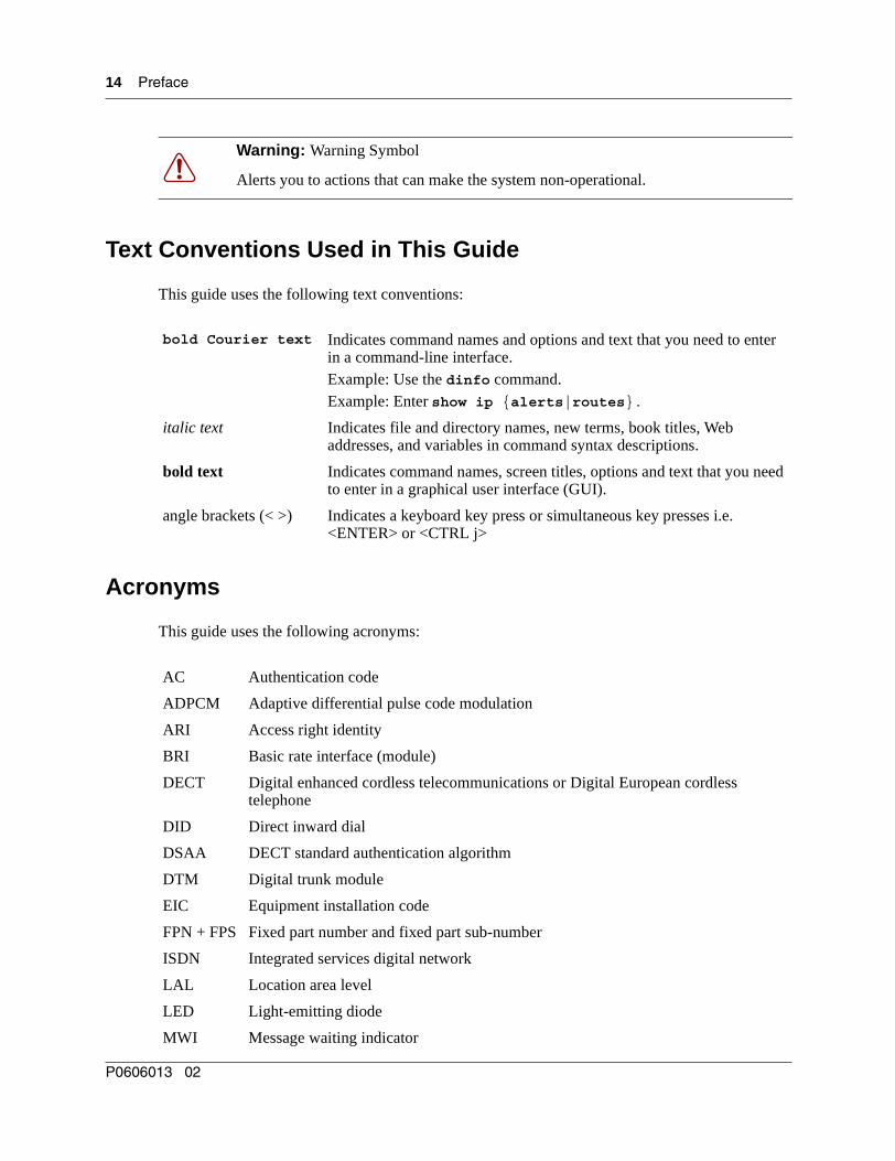
Warning: Warning Symbol
Alerts you to actions that can make the system non-operational.
bold Courier text Indicates command names and options and text that you need to enter in a command-line interface.Example: Use the dinfo command. Example: Enter show ip {alerts|routes}.
italic text Indicates file and directory names, new terms, book titles, Web addresses, and variables in command syntax descriptions.
bold text Indicates command names, screen titles, options and text that you need to enter in a graphical user interface (GUI).
angle brackets (< >) Indicates a keyboard key press or simultaneous key presses i.e. <ENTER> or <CTRL j>
AC Authentication code
ADPCM Adaptive differential pulse code modulation
ARI Access right identity
BRI Basic rate interface (module)
DECT Digital enhanced cordless telecommunications or Digital European cordless telephone
DID Direct inward dial
DSAA DECT standard authentication algorithm
DTM Digital trunk module
EIC Equipment installation code
FPN + FPS Fixed part number and fixed part sub-number
ISDN Integrated services digital network
LAL Location area level
LED Light-emitting diode
MWI Message waiting indicator
P0606013 02
Preface 15
Related Publications
For more information about the Business Communications Manager server and related media bay modules, extension equipment, and the applications and software on the system, refer to the following publications, which are located on the CD that came with your Business Communications Manager system or upgrade:
• Installation and Maintenance Guide describes the process of installing and maintaining the Business Communications Manager equipment. The book includes descriptions of the available modules.
• Programming Operations Guide describes how to program the Business Communications Manager equipment.
• If your Business Communications Manager has an internal voice mail system, refer to the documents specific to your system for setting up voice mail for your DECT handsets. If your system is part of a network connected to a Meridian system voice mail, refer to the Meridian voice mail documentation.
PARI Primary access right identity
PARK Portable access right key
PARK{y} PARK with PLI y
PBX Private branch exchange
PLI Park length indicator
PSTN Public switched telephone network
RFPI Radio fixed park identity
RSSI Radio signal strength indicator
SARI Secondary ARI
TCM Time compressor multiplexor
WAN Wide area network
DECT Installation and Maintenance Guide

16 Preface
P0606013 02

17
Chapter 1DECT system overview and requirements
The DECT system provides the Business Communications Manager with the ability to connect cordless telephones to the system for use within the local area.
There are specific Business Communications Manager profiles that can use this equipment. Refer to “Checking the System Region” on page 30. Other profiles are for countries that have other technology for this purpose.
This chapter describes the DECT system components and provides an overview of the installation process. It also includes instructions for ensuring that your Business Communications Manager is set to the correct profile to accept and work with the DECT equipment.
The information in this section includes:
• “DECT features” on page 19
• “Setup process overview” on page 21
• “DECT base station deployment planning” on page 22
• “DECT radio base station” on page 22
• “DECT cordless handsets” on page 27
• “Site configurations” on page 27
• “DECT call paths” on page 27
• “DECT programming overview” on page 28
• “Business Communications Manager requirements” on page 29
• “Checking the System Region” on page 30
Deployment and site preparation details are provided in a separate document. This section provides a brief overview of this task, as well as the specifications for the components.
This section also provides an overview of system operations. This includes the load required on the Business Communications Manager and general commands you require to work on the DECT interface.
Warning: Do not attempt to change a region setting on an active system. This can cause the system to reset and lose data.
DECT Installation and Maintenance Guide

18 Chapter 1 DECT system overview and requirements
The following figure shows a graphic representation of the components of the system.
Figure 1 Integrated DECT service
The following table describes the three main hardware components of the DECT system.
Table 1 Hardware components of the DECT system
Component Function
DECT media bay module The module connects up to eight radio base stations. Use the Business Communications Manager Unified Manager application to initialize and program the module.Within the module, four BRI ISDN loops allow up to eight simultaneous conversations. NOTE: Each Business Communications Manager system can support one DECT module.
M6241 Radio base station Each base station provides radio coverage for a prescribed area. A group of base stations make up a cell. Each base station can support up to four simultaneous calls. The radio base stations also offer antenna diversity.
Use the site survey to determine the number of base stations required to cover the area. Refer to “DECT base station deployment planning” on page 22.
DECT cordless handset C4010 and C4020
Each handset provides the user with telephony features remote from the land set. This book contains only the registration operations for the set. Refer to the user manuals that came with your handset for operational details. Up to 32 handsets can be assigned to each DECT system.
Business Communications Manager
DECT media bay module
Base stations
Handsets
P0606013 02

Chapter 1 DECT system overview and requirements 19
DECT features
The following list describes some of the special features of the DECT system.
• The DECT module contains four BRI ISDN-S loops. The Business Communications Manager assigns four loop records in the Unified Manager when the module is installed, based on the DIP switch settings for the module.
• The cordless handsets are identified with DNs in the Unified Manager. They can be assigned answer DNs to link them with stationary sets.
• The numbering plan and call routing defined in the Business Communications Manager must agree with the entries in the DECT interface.
Also refer to “Handset system features” on page 71.
Business Communications Manager features
The DECT system supports the following Business Communication Manager call processing features:
• autodial keys (handset-based)
• answer keys
• busy lamp indication
• call capture
— incoming calls can be redirected to the prime set or a voice mail boxNote: DECT handsets only can only access voice mailboxes (FEATURE 981) and receive only associated message waiting indicators (MWI) for new messages. Other voice mail functions, Call Center features, Attendant Console, TAPI applications or CTE applications are unavailable to DECT handsets. Symbol© NetVision© wireless handsets are the only portable system that supports these applications from the Business Communications Manager.
— a system telephone calling a DECT handset will continue to ring even after the handset ring timer runs out. It is recommended that all DECT handsets be set for Call Forward No Answer to deal with this issue.
• call display when busy: handsets will only get a busy signal
• call forward (all calls, busy, no answer) • call identification: available, depending on system programming• class of service/dialing restrictions• conference calling• delayed Ring Transfer to Prime if the DECT handset is not answered• dial external/outgoing line identification• intercom lines• external line access using line pool codes or destination codes• hold
DECT Installation and Maintenance Guide
20 Chapter 1 DECT system overview and requirements
• hunt group functionality• multiple line appearances• on hook dialing• private lines (incoming)• remote access• ringing, restriction, and routing services• set name• target line (direct call from external line)• transfer• voice mail support to retrieve pending messages
Features not included on this list are not supported on the handset by the Business Communications Manager system.
Handset features
These features are provided by the DECT handset, and are not necessarily exclusive to Business Communications Manager operation.
• dial pad feedback• feature access key• headset• hearing aid compatibility• language choice• last number redial• on hook dialing from numbers stored in handset memory• ringing line preference• set speed dial
Refer to the DECT documentation that came with the handset for details.
P0606013 02

Chapter 1 DECT system overview and requirements 21
Setup process overviewThe following figure provides an overview of the actions required to successfully set up the DECT integrated system:
Figure 2 Setup process for the DECT system
Maintenance tools
Plan the deployment
Install media bay
module
Program the DECT module
Install the radio base
stations
Have a site plan and deployment strategy worked out. Refer to the M6261DECT Deployment Tool Guide on the Business Communications Manager CD.Data report Site surveyRadio base stations locations Plan cells
Refer to Chapter 4, “Installing the DECT base station,” on page 53.Check the site map for obstacles and possible sources of interference to the radio signal or data link.
Refer to Chapter 2, “Installing the DECT media bay module,” on page 31. This procedure assumes the Business Communications Manager is installed and commissioned.
The first radio base station must be within 800 m of the DECT media bay module. Attach the components using 0.6 mm cable.
Connectbase stations
to module
Refer to “Configuring the DECT module” on page 37 for instructions about setting up the module through the Unified Manager, and running the DECT wizards. Chapters 6 to 8 provide instructions for manually configuring the DECT module settings.
Subscribecordless handsets
Refer to Chapter 5, “Subscribing DECT cordless handsets,” on page 61.When the system and module DNs have been assigned, subscribe each handset. Test the handsets with each base station.
Check BCM system
settings
Ensure that your Business Communications Manager has the correct Region setting to allow DECT deployment. Refer to “Checking the System Region” on page 30.
For some functions, DECT works separately from other applications on the Unified Manager. Use the tools found under the Maintenance button on the first page of the Unified Manager to perform these functions: Time synch, Firmware upload, Backup/Restore/Scheduling, Restore default, and viewing the current Companding law setting.
DECT Installation and Maintenance Guide

22 Chapter 1 DECT system overview and requirements
DECT base station deployment planning
The DECT base stations must be deployed to provide full site coverage with the maximum traffic capacity, using the minimum number of base stations.
There are two tasks involved in arranging this:
• Surveying the site: the site survey involves gathering information to determine customer requirements and the number of cells needed to support the traffic.
• Planning deployment: deployment plans establish the best locations for the radio base stations.
Site surveying and deployment planning are complex tasks, undertaken only by trained personnel. Refer to the M6261DECT Deployment Tool and site planning guide for detailed Site planning and deployment.
DECT radio base station
The Business Communications Manager can support one DECT media bay module.
The information in this section includes:
• “External antennas” on page 23
• “Specifications for DECT radio base stations” on page 25
• “Base station notes:” on page 26
• “Description of the connection” on page 26
A cable attached to an RJ45 connector in the face of the DECT module connects to the base station RJ45 connector. This supplies the data and power.
The base station comes with two internal antennas to provide signal diversity. Some types of external antennas can be substituted, depending on site requirements.
The following table describes the function of the parts of the base station.
Table 2 Parts of the DECT radio base station configurations
Part Description of function
Base stations The area covered by the base station depends on the radio range. Base stations manage the links with the cordless handsets within that range.
Cables The cable includes two telephone pairs.One transmits the signal.
One receives the signal.
Connectors The base station uses a female RJ45 to connect to the cable.
P0606013 02

Chapter 1 DECT system overview and requirements 23
External antennas
Three kinds of external antennas can be added:
• The MA431X23 is omnidirectional with an extension cord.
• The MA431X24 is omnidirectional with an extension cord.
• The MA821X12 is bidirectional with a 50-cm cable.
The HT6176A is an adapter for outdoor antennas.
Switches There are two configuration switches: the CA1 and the S202.• The CA1 has two switches, labelled 1/2 and 3/4.
Set 1/2 to On to enable the adaptation resistor for the synchronization pair.Set 3/4 to On to enable base station Reset.
Set 3/4 to Off to run Reset by S0 interface level 1.• The S202 has two switches, labelled 1/2 and 3/4.
Set 1/2 and 3/4 to On to enable the 100 ohm adaptation resistors for the S0 pairs.
Refer to Figure 3 on page 23.
Figure 3 Base station switches
Warning: Do not add any longer cables to the MA821X12, or the gain and receptivity will suffer. Place this antenna as close to the base station as possible.
Table 2 Parts of the DECT radio base station configurations (continued)
Part Description of function
Jack
RJ45
S202 CA1On On
Reset
Adaptation synchronizer
Adaptation RNIS1 12 2
33
44
DECT Installation and Maintenance Guide

24 Chapter 1 DECT system overview and requirements
The MA431X23 and X24 antennas can be installed further from the base station. Ensure that the coaxial cables linking the antennas with the base stations provide low attenuation. The following figure illustrates two configurations:
Figure 4 Antenna configurations
• The internal antenna incorporates an MMS connector (1), one coaxial cable KX21 (2) and the radiating element (3). The antenna gain is 2 dBi.
• The external antenna is connected via a cord (4-5-6) which incorporates an MMS male connector (4), coaxial cable KX21 (5) and a TNC female connector (6). The manufacturer specifies losses of less than the guaranteed dB value. Losses are actually of the order of 0.7 dB at 2 GHz.
The extension cord conveying the signal to the antenna incorporates a TNC male connector (7), low loss coaxial RG58cu cable (8) and N male connector (9). The antenna (11) is secured to the extension cord using N female connector (10).
The losses generated by this extension cord are summarized in the following table.
• The maximum length of the extension cord is 2.8 meters.
• The MA432X23 external antenna with an extension cord performs approximately in the same way as an internal antenna, except for the polarization diversity.
• The MA432X24 provides a 2 dB gain compared to the internal antenna.
Table 3 Generated losses with extension cord added
Element Losses at Frequency Estimated losses
RG58cu 0.65dB/m at 2GHz
TNC 0.2 dB at 9GHz 0.1 dB
N 0.15 dB at 10GHz 0.1 dB
P0606013 02
Chapter 1 DECT system overview and requirements 25
Specifications for DECT radio base stations
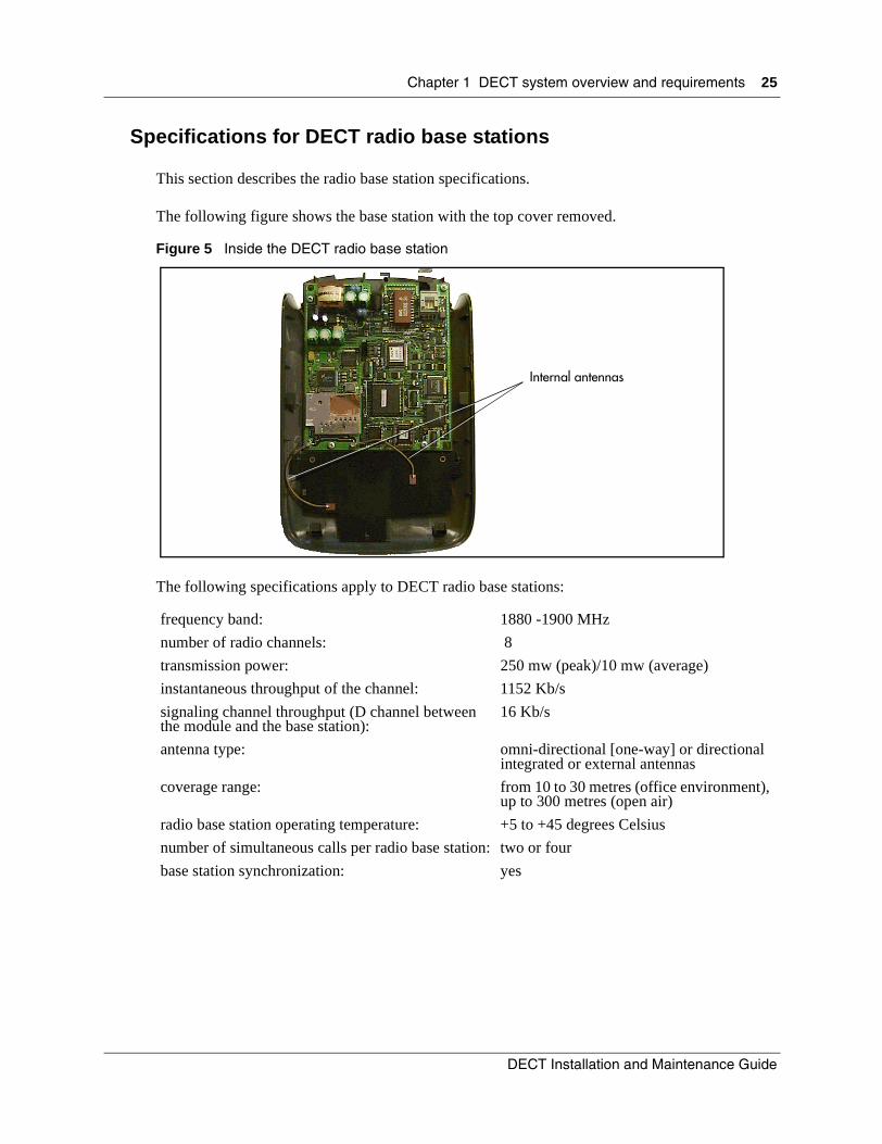
This section describes the radio base station specifications.
The following figure shows the base station with the top cover removed.
Figure 5 Inside the DECT radio base station
The following specifications apply to DECT radio base stations:
frequency band: 1880 -1900 MHz
number of radio channels: 8
transmission power: 250 mw (peak)/10 mw (average)
instantaneous throughput of the channel: 1152 Kb/s
signaling channel throughput (D channel between the module and the base station):
16 Kb/s
antenna type: omni-directional [one-way] or directional integrated or external antennas
coverage range: from 10 to 30 metres (office environment), up to 300 metres (open air)
radio base station operating temperature: +5 to +45 degrees Celsius
number of simultaneous calls per radio base station: two or four
base station synchronization: yes
Internal antennas
DECT Installation and Maintenance Guide

26 Chapter 1 DECT system overview and requirements
Base station notes:
Here are some general-information notes about the base station:
• Do not install more than two overlapping radio base stations per cell.
• Do not apply any paint or other wall covering to the plastic shell without written approval from Nortel Networks.
• Use the Unified Manager to perform resets of the base station.
• Signal processing functions for the four-channel radio base station are ported to the media bay module. In this case, the interface transports four 32 Kb/s ADPCM coded communications as well as 16 Kb/s signaling channel.
Climatic conditions
The DECT base station can tolerate the following conditions:
Operational:
• Temperature: 5 to 45 degrees C.
- 20 to +60 with a special cabinet
• Relative humidity: 10 to 80%, not condensing.
Storage:
• Temperature range: - 10 to 60 degrees C.
• Relative humidity range: 10 to 90%, not condensing.
Power supply
The ISDN interface in the DECT media bay module enables the base stations to be powered through the cable connection between the DECT and the base station. The remote power supply is limited to 100 mA on the DECT interface, which corresponds to an available power of 4 W at 48V.
The radio base station can also be powered using a local a.c./d.c. mains power supply unit, PN 840 B. Use a local supply unit for no more than two radio base stations in any given cell.
Description of the connection
DECT base stations connect to DECT media bay modules using a cable containing two twisted pairs. This cable connects to RJ45 connectors on the components. The connection at the DECT position corresponds to an equipment number on the two cards on the DECT module that control the base station interaction. If you assign specific base stations to equipment numbers, you must ensure that base station is connected to the appropriate RJ45 jack on the DECT module.
P0606013 02

Chapter 1 DECT system overview and requirements 27
DECT cordless handsets
This section describes the features provided by the C4010 and C4020 cordless handsets. These handsets were developed to work with DECT systems.
Other cordless handsets can be used with the DECT system. The system features available to other handsets depends on how the handset is configured, and how compatible it is with the signals transmitted from the DECT module. As well, some features such as call display also require the proper line configurations at both the local and telco end of the line.
Site configurations
Nortel Networks provides one PARI number on the DECT module that all the base stations share. Access is authorized by matching the PARI number and the PARK number registered in the Other multi-site configurations.
DECT call paths
The DECT module provides a telephony path separate from the Business Communication Manager system. This means there are three possible paths for a call to take.
• A DECT handset-to-handset call is routed from the calling handset, through the DECT module C8 interface, into the receiving handset.
• A DECT handset-to-Business Communications Manager set call is routed from the calling handset, into the C8 interface, and into the Business Communications Manager. The Business Communications Manager then routes the call through the appropriate station module to the receiving set.
• A DECT handset-to-external call is routed from the calling handset, into the C8 interface, and into the Business Communications Manager. The Business Communications Manager then routes the call through the appropriate trunk module out to the public network. This is the same route a call from a DECT handset to a set on a private network would use. The difference is that the user enters a different destination code.
• If a DECT handset transfers a call, the DECT C8 processes the transfer and creates a new call destination. The call remains routed through the C8 interface, even though the DECT handset is no longer involved in the call.
Check for small metal objects in the DECT Handset earpiece/mouthpiece before using the handset.
Do not store or locate flammable liquids, gases, or explosive materials in the same compartment or vicinity as the cordless handset, its parts or accessories.
DECT Installation and Maintenance Guide
28 Chapter 1 DECT system overview and requirements
DECT programming overview
Here are some important points about using DECT on your Business Communications Manager.
• The Business Communications Manager must be configured with a region setting that provides DECT support.
• The system default password is set to insta. You can delete or change this password to suit your needs.
• Default language is English.
• Disable the base stations before a firmware upgrade. Put the base stations back in service in sequence.
• To subscribe handsets, a base station must be set to accept handset recording.
• The handset DN must also be set into recording mode before the handset can be subscribed.
• The system uses data links.
• Within the DECT interface, numbers enclosed in ( ) indicate length of parameters. Refer also to “DECT interface commands” on page 28 and “Numbering plan syntax” on page 29.
DECT interface commands
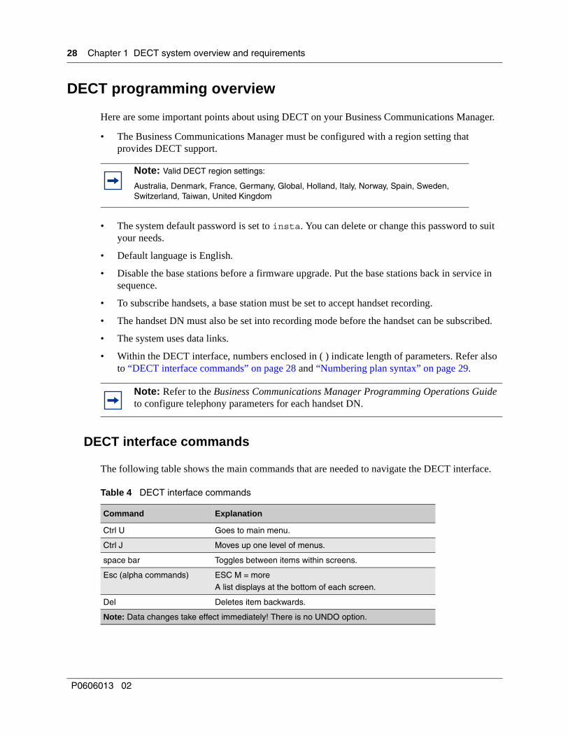
The following table shows the main commands that are needed to navigate the DECT interface.
Note: Valid DECT region settings:
Australia, Denmark, France, Germany, Global, Holland, Italy, Norway, Spain, Sweden, Switzerland, Taiwan, United Kingdom
Note: Refer to the Business Communications Manager Programming Operations Guide to configure telephony parameters for each handset DN.
Table 4 DECT interface commands
Command Explanation
Ctrl U Goes to main menu.
Ctrl J Moves up one level of menus.
space bar Toggles between items within screens.
Esc (alpha commands) ESC M = moreA list displays at the bottom of each screen.
Del Deletes item backwards.
Note: Data changes take effect immediately! There is no UNDO option.
P0606013 02
Chapter 1 DECT system overview and requirements 29
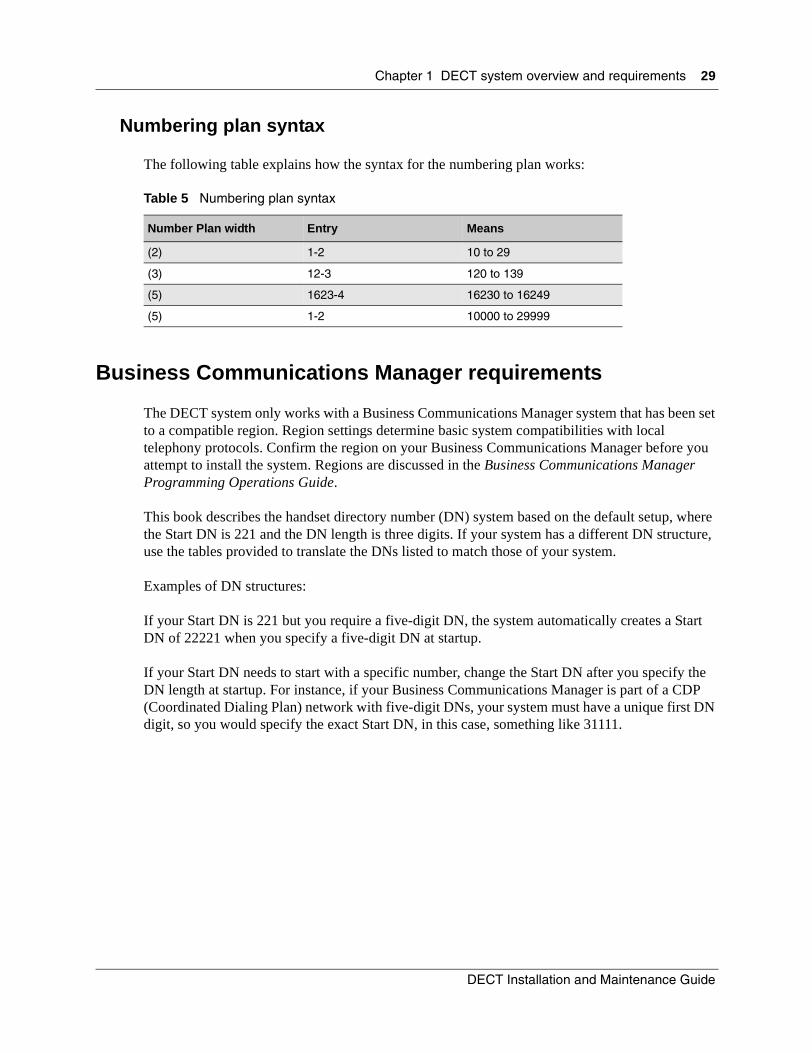
Numbering plan syntax
The following table explains how the syntax for the numbering plan works:
Business Communications Manager requirements
The DECT system only works with a Business Communications Manager system that has been set to a compatible region. Region settings determine basic system compatibilities with local telephony protocols. Confirm the region on your Business Communications Manager before you attempt to install the system. Regions are discussed in the Business Communications Manager Programming Operations Guide.
This book describes the handset directory number (DN) system based on the default setup, where the Start DN is 221 and the DN length is three digits. If your system has a different DN structure, use the tables provided to translate the DNs listed to match those of your system.
Examples of DN structures:
If your Start DN is 221 but you require a five-digit DN, the system automatically creates a Start DN of 22221 when you specify a five-digit DN at startup.
If your Start DN needs to start with a specific number, change the Start DN after you specify the DN length at startup. For instance, if your Business Communications Manager is part of a CDP (Coordinated Dialing Plan) network with five-digit DNs, your system must have a unique first DN digit, so you would specify the exact Start DN, in this case, something like 31111.
Table 5 Numbering plan syntax
Number Plan width Entry Means
(2) 1-2 10 to 29
(3) 12-3 120 to 139
(5) 1623-4 16230 to 16249
(5) 1-2 10000 to 29999
DECT Installation and Maintenance Guide

30 Chapter 1 DECT system overview and requirements
Checking the System Region
If you experience problems configuring the DECT module on your system, check the region for which the system is set.
This procedure describes how to ensure that the Business Communications Manager is set to the correct region for the DECT module.
1 Open the Unified Manager for your Business Communications Manager system.
2 On the navigation tree, click Diagnostics/MSC.
3 On the top menu, click on Configuration.
4 Click System startup.
5 Ensure that the Region box displays the correct region.
a To change the region, select a region from the list.
b Click OK to apply these changes.The system displays a warning that the system will restart and that the default programming values will be restored.
c Click Cold Start to restart the Unified Manager.
6 Continue with the DECT deployment.
Note: DECT systems can be installed in countries that can run the following region profiles: UK, Australia, Sweden, Denmark, Holland, Norway, Italy, Germany, Spain, Switzerland, France, Global, Taiwan.
Refer to the Business Communications Manager Programming Operations Guide appendices for the table that lists all the regions.
Caution: You must select a region that reflects the geographical location of the Business Communications Manager.If you choose the incorrect region, the Business Communications Manager system does not communicate correctly with the Public Switched Telephone Network.
Warning: If you reset the region profile on the Business Communications Manager, the system is reset to default parameters. Therefore, ensure that you have a current backup before you attempt to do this procedure.
Note: When you select a new region, the Template box is disabled. You must restart the system before the templates for the selected region are available.
P0606013 02

31
Chapter 2Installing the DECT media bay module
This section describes how to install the DECT media bay module in the Business Communications Manager. The following flow chart shows an overview of the process.
Figure 6 Process for installing the DECT module
Base stations are installed
Set the DIP switches on the back of the
DECT module
Note the PARI number on the side of the
module
Shut down the system
Install the DECT module
Go to Chapter 3, “Configuring the DECT module,” on page 37 to
perform the module identification and
initialization.
Remove the front bezel
Prepare system for shutdown
Remove the media bay cover
Restore system to operation
Site planning is complete
DECT Installation and Maintenance Guide

32 Chapter 2 Installing the DECT media bay module
Setting the DIP switches
This procedure describes how to set the DIP switches for the DECT media bay module.
1 Take the media bay module from its box.
2 Inspect the module for damage.
3 Make a note of the PARI number, which is located on a label on the module.
4 Determine which DS30 channel (bus) number to use for the module.
5 Set the DIP switches, located on the back of the DECT module to the DS30 channel number. Set the offset to 0 (on).
The following figure shows the location of the DIP switches on the DECT module.
Figure 7 Locating the DECT media bay module dip switches
Ensure that you wear equipment to properly ground yourself while handling any of the electronic parts to this system.
Note: Remember that the bus you choose cannot conflict with a location already assigned to an existing media bay module.
Use Bus 6 or 7 if they are available.
1 2 3 4 5 6On
Off
P0606013 02

Chapter 2 Installing the DECT media bay module 33
• The following table shows the switch settings for each DS30 channel number. The offset number is always 0.
Use the following table to note the settings you chose.
Table 6 DECT switch settings
Select DS30
channel
Select offset
Set the switches Use these DNs on new
2.5 or greater
systems
Use these DNs on
updated 2.0 system
**Customized DN range
Offset DS30 channel
1 2 3 4 5 6
2 0on on on on on on
597-624* 501-532*
3 0on on on on on
597-624* 501-532*off
4 0on on on on on
597-624* 501-532*off
5 0on on on on
597-624* 501-532*off off
6 0on on on on on
597-624* 501-532*off
***7 0on on on on
597-624* 501-532*off off
*If you need more DNs, use DNs in the portable DNs, starting at 565. Ensure no other devices are assigned to these DNs before you use them.**Note: The extensions listed are based on a three-digit DN with a Start DN of 221. If your system has longer DNs or a different Start DN, enter the range in the blank column.***If your system has a 3/5 DS30 channel split, channel 7 is not available to media bay modules. Refer to the Business Communications Manager Programming Operations Guide for further information on this feature.
Note: If you replace a module, set the DIP switches for the new module to exactly the same settings as the removed module.
TIP: Numbering conventions:
This document assumes three-digit DNs, starting with a Start DN of 221. If your system has a different numbering plan, adjust the numbering accordingly. If you follow a different numbering plan, ensure that you update all the DN settings described in Chapter 8, “Programming DECT handset records,” on page 93.
Table 7 Module settngs
Module PARI number:
DS30 channel:
DIP switch settings:
Notes:
DECT Installation and Maintenance Guide

34 Chapter 2 Installing the DECT media bay module
Installing the DECT module
After you have set the DIP switches, you can install the module. You need to shut down the system to install the module, therefore, choose a period when the Business Communications Manager is not busy.
Remember to warn users that the system will be down for a short period.
1 Ensure the Business Communications Manager base unit is properly shut down.
a From the Unified Manager application, click System, then go to the Logoff menu and click Shutdown.
For detailed shutdown information, refer to the Business Communications Manager Programming and Operations Guide.
b Disconnect all the cables from the front of the Business Communications Manager base unit and expansion unit, if there is one.
c Disconnect the base unit and expansion unit power cords from the a.c. outlet.
d Remove the front bezel from the front of the base unit or expansion unit where you plan to install the DECT module.
2 Remove the blank cover from the module bay.
To remove the bay cover, pull the tab beside the module bay. This pushes the cover forward. The following figure shows the module release tabs on the base unit and expansion unit.
Figure 8 Release tabs for the module bays
Danger: Failure to follow these steps can result in damage to the system or the module.
Media bay coverplate and module release tabs
Business Communications Manager base unit
Business Communications Manager expansion unit
P0606013 02

Chapter 2 Installing the DECT media bay module 35
3 Insert the module into the open bay and push until the module clicks into the backplate.
4 Replace the front bezel on the base unit or the expansion unit.
The following figure shows the base unit and expansion unit with the front bezels replaced.
Figure 9 Front bezels replaced on units
5 Refer to the following section to restore the system.
Restoring the system
After the module is installed, restore the Business Communications Manager operations. Then connect the base station cables to the module.
1 Inspect the system to ensure all components are in place.
2 Reconnect the a.c. power cords for the Business Communications Manager base unit and the expansion unit, if there is one.
3 Reconnect all the connections to the front of the units.
4 Monitor the LEDs on the front of the DECT module to ensure the system reboots properly. Refer to the following figure. This process takes a few minutes.
— Power (working status)
— Status (hardware status)
— Run (CPU of the DECT C8 interface) (blinks when stable)
Note: The module protrudes slightly. After the front bezel is replaced, the face of the module sits flush with the front of the unit.
Warning: Failure to properly reconnect the system, as described in this procedure, can result in damage to the system or the module.
Business Communications Manager base unit
Bezels replaced on units
Business Communications Manager expansion unit
DECT Installation and Maintenance Guide

36 Chapter 2 Installing the DECT media bay module
— 48 V for the base station jacks
Figure 10 Locating the LEDs on the DECT module face
5 When the power and status LEDs on the module are solid green, you are ready to continue with the module configuration. Refer to Chapter 3, “Configuring the DECT module,” on page 37.If the lights are off or are blinking, refer to “Monitoring the DECT module LEDs” on page 114 for troubleshooting information.
Power LEDStatus LED
Run
Base station power
P0606013 02
37
Chapter 3Configuring the DECT module
There are some preliminary steps that you must do within the Business Communications Manager Unified Manager application before you run the wizard that configures the DECT module. This section describes how to ensure that the Business Communications Manager system sees the DECT module. It also describes how to find and manage the DNs designated for DECT handsets.
When the Unified Manager settings have been done, you can run the DECT Configuration wizard. This wizard configures the DECT module. It also turns on one of the base station ports to allow handset subscription.
Handset subscription (mobile recording) can also be turned on and off using the DECT Mobile Recording (handset subscription) wizard, which is described in “DECT Mobile Recording (Handset Subscription) Wizard” on page 63.
This section contains the following headings:
• “Process overview: Identify and configure the DECT Module” on page 38
• “Confirming the DECT module” on page 39
• “Configuring the module for µ-law” on page 40
• “Checking the Unified Manager handset DNs” on page 43
• “Setting up the handsets” on page 44
• “About the DECT Wizards” on page 47
DECT Installation and Maintenance Guide
38 Chapter 3 Configuring the DECT module
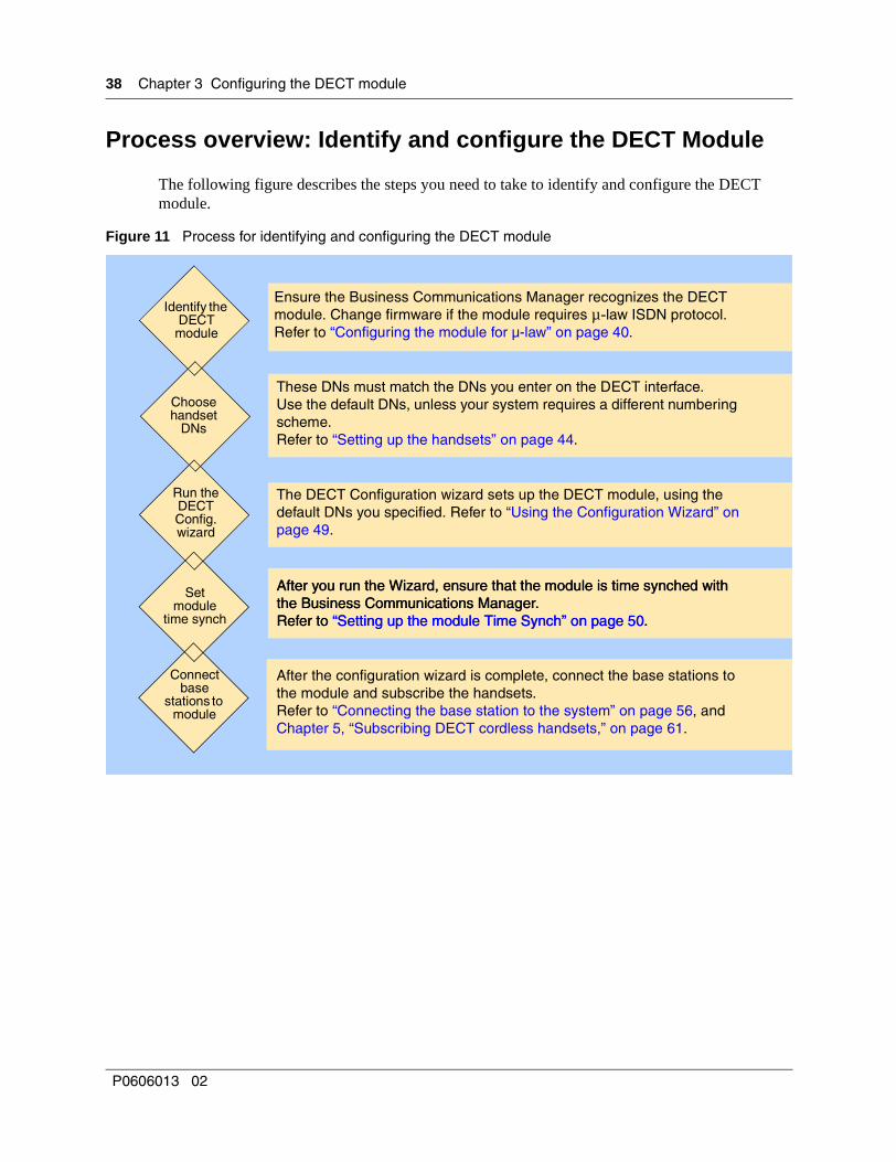
Process overview: Identify and configure the DECT Module
The following figure describes the steps you need to take to identify and configure the DECT module.
Figure 11 Process for identifying and configuring the DECT module
Choose handset
DNs
Run the DECT Config. wizard
The DECT Configuration wizard sets up the DECT module, using the default DNs you specified. Refer to “Using the Configuration Wizard” on page 49.
These DNs must match the DNs you enter on the DECT interface. Use the default DNs, unless your system requires a different numbering scheme.Refer to “Setting up the handsets” on page 44.
Setmodule
time synch
After you run the Wizard, ensure that the module is time synched with the Business Communications Manager.Refer to “Setting up the module Time Synch” on page 50.
Identify the DECT
module
Ensure the Business Communications Manager recognizes the DECT module. Change firmware if the module requires µ-law ISDN protocol. Refer to “Configuring the module for µ-law” on page 40.
Connect base
stations to module
After the configuration wizard is complete, connect the base stations to the module and subscribe the handsets.Refer to “Connecting the base station to the system” on page 56, and Chapter 5, “Subscribing DECT cordless handsets,” on page 61.
After you run the Wizard, ensure that the module is time synched with the Business Communications Manager.Refer to “Setting up the module Time Synch” on page 50.
P0606013 02
Chapter 3 Configuring the DECT module 39
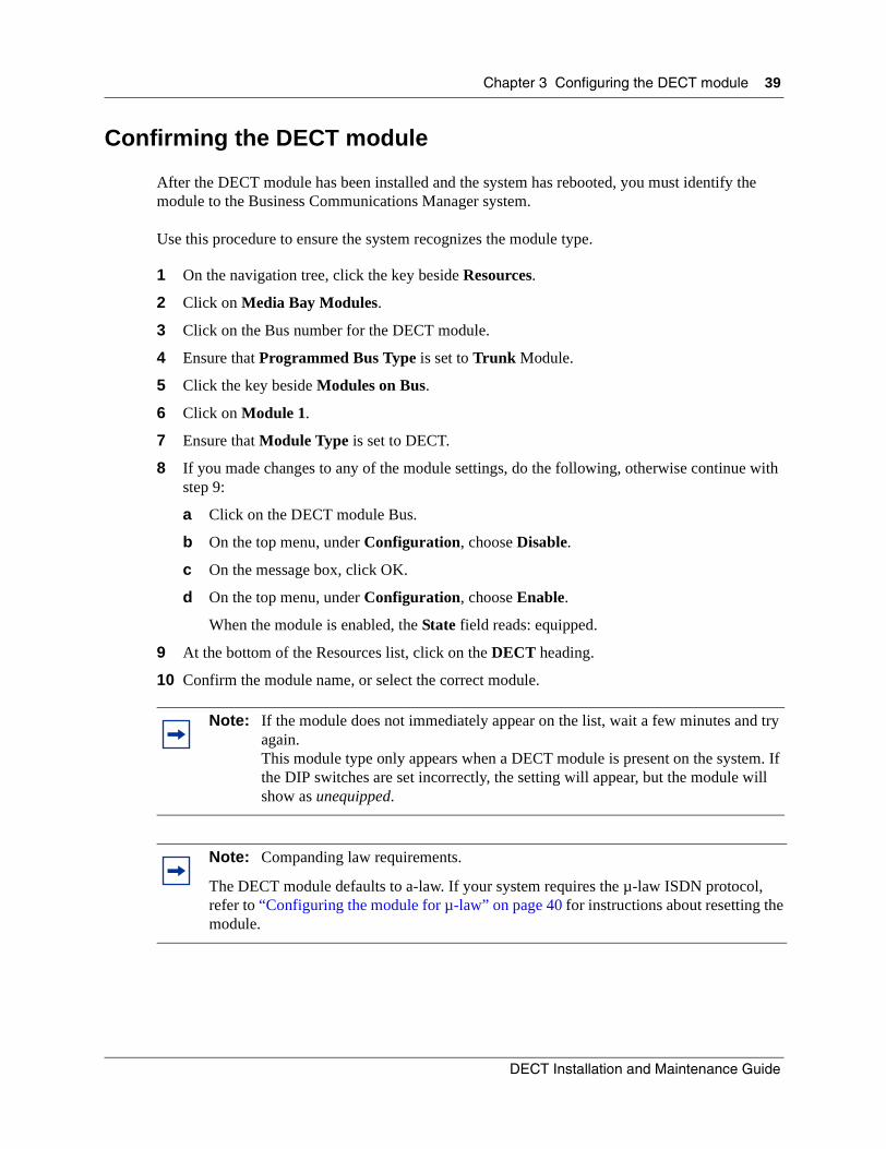
Confirming the DECT module
After the DECT module has been installed and the system has rebooted, you must identify the module to the Business Communications Manager system.
Use this procedure to ensure the system recognizes the module type.
1 On the navigation tree, click the key beside Resources.
2 Click on Media Bay Modules.
3 Click on the Bus number for the DECT module.
4 Ensure that Programmed Bus Type is set to Trunk Module.
5 Click the key beside Modules on Bus.
6 Click on Module 1.
7 Ensure that Module Type is set to DECT.
8 If you made changes to any of the module settings, do the following, otherwise continue with step 9:
a Click on the DECT module Bus.
b On the top menu, under Configuration, choose Disable.
c On the message box, click OK.
d On the top menu, under Configuration, choose Enable.
When the module is enabled, the State field reads: equipped.
9 At the bottom of the Resources list, click on the DECT heading.
10 Confirm the module name, or select the correct module.
Note: If the module does not immediately appear on the list, wait a few minutes and try again.This module type only appears when a DECT module is present on the system. If the DIP switches are set incorrectly, the setting will appear, but the module will show as unequipped.
Note: Companding law requirements.
The DECT module defaults to a-law. If your system requires the µ-law ISDN protocol, refer to “Configuring the module for µ-law” on page 40 for instructions about resetting the module.
DECT Installation and Maintenance Guide
40 Chapter 3 Configuring the DECT module
Configuring the module for µ-law
The Business Communications Manager has the software for both µ-law and a-law ISDN protocols. The system defaults to a-law, as does the DECT module. To change this setting on the DECT module in countries where µ-law is required, you need to upload a new set of firmware. Follow the directions in this section to set up the module and upload this firmware.
If your system uses the a-law protocol, skip to “Checking the Unified Manager handset DNs” on page 43.
Before you start
Ensure that the following has been done before you attempt to upload new firmware to the DECT module.
1 Ensure that the Business Communications Manager system has been initialized with the correct µ-law Region profile. Refer to “Checking the System Region” on page 30.
2 If you are unsure of what your DECT module is set to, you can check the setting through the DECT module. Refer to “Determining module companding law setting” on page 115.
3 To view the companding law for the firmware that is ready to be loaded, you can check under DECT Tools. Refer to “Setting up the DECT file for upload” on page 41 for a detailed process for finding the DECT Tools pages under the Maintenance button on the first page of the Unified Manager.
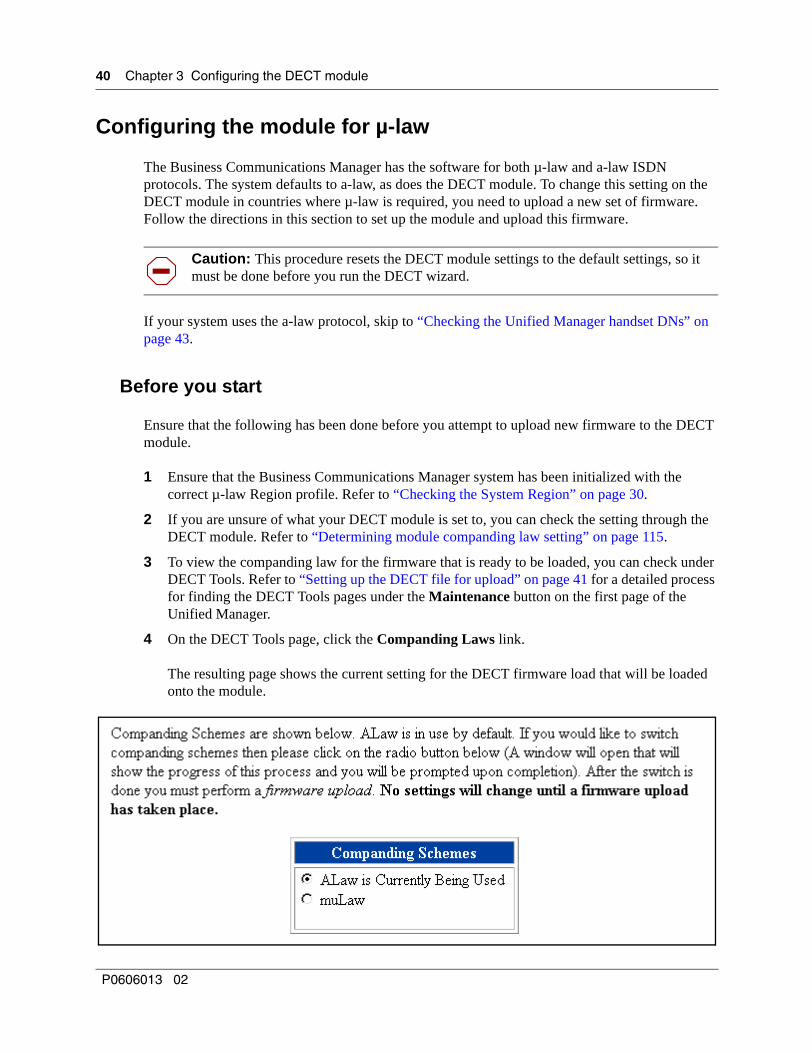
4 On the DECT Tools page, click the Companding Laws link.
The resulting page shows the current setting for the DECT firmware load that will be loaded onto the module.
Caution: This procedure resets the DECT module settings to the default settings, so it must be done before you run the DECT wizard.
P0606013 02

Chapter 3 Configuring the DECT module 41
Setting up the DECT file for upload
The first step is to set up the file that needs to be uploaded by the module.
1 On the Unified Manager first page, click on the Maintenance button.
2 On the left menu of the maintenance site, click on Maintenance tools.The following menu appears.
Figure 12 Maintenance Tools menu
3 Beside the DECT heading, click on the Firmware Upload link.The firmware upload page appears.
DECT Installation and Maintenance Guide

42 Chapter 3 Configuring the DECT module
Figure 13 Firmware upload
4 Beside Please enter your DECT installer Password, type: insta*
5 Click the Execute DECT Firmware Upload button.The upload screen appears and remains until the upload is complete.
Resetting the module to default valuesNow you must reset the module to default values.
1 You should still be in the DECT Tools section.
2 Click on the Restore Default Configuration link.The Restore Default Firmware page appears.
Figure 14 Restore default firmware configuration
3 Beside Please enter your DECT installer Password, type: insta*
Note: *The Password listed here is the default. Your system settings may have been changed.
Note: The log file notes if the upload is successful. If the upload fails, go back and ensure that you have the correct DECT password.
Note: *The Password listed here is the default. Your system settings may have been changed.
P0606013 02
Chapter 3 Configuring the DECT module 43
4 Click on the Restore Default Configuration button.
5 The restore default configuration operation begins.
6 Once this step is complete, you are ready to set up the Business Communications Manager records and run the DECT Configuration wizard and time synch processes, as described in the following sections of this chapter.
Checking the Unified Manager handset DNs
The DECT handset is considered an ISDN S device. Assign the handset to DNs within the default ISDN and DECT range. Ensure that you do not assign handset DNs that have already been assigned to other ISDN devices.
Note: The log file notes if the upload is successful. If the upload fails, go back and ensure that you have the correct DECT password.
Note: Default DECT module DNs:
• New 2.5 and greater Business Communications Manager: 597-624
• Upgraded 2.0 Business Communications Manager: 501-532
These defaults assume a system with a three-digit DN structure, and a Start DN of 221. If your system is different, use these numbers as guidelines to find the defaults to your system.
Note: If you need more DNs than are available in the default range, use the Companion DNs. Ensure these DNs are available before assigning them, then choose ISDN and DECT for the DN Type field.
Warning: It is imperative for the DECT module programming, that the DNs for your DECT handsets are within a range of DNs. If you assign handsets to DNs outside of a range, use the DN Renumber Wizard to renumber the DNs on the Business Communications Manager to create a range. Make sure you do not overwrite any DNs already in existence when you do this.
The issue: The DECT media bay module programming only has 12 lines to accommodate handset DNs, therefore, if you specify more than 12 individual DNs, and try to run the DECT Quick Start Wizard, the Wizard will fail.
Note: If you want to identify the handsets with the CO line number assigned to them, enter this number in the Name field for the DN record assigned to that handset.
DECT Installation and Maintenance Guide

44 Chapter 3 Configuring the DECT module
To check the handset records in the Unified Manager, follow these steps:
1 Open the Unified Manager.
2 From the menu, click BCM, Services, Telephony Services, System DNs, All ISDN/DECT DNs.
3 Click on the DN number you want to assign to the handset.
4 Under the DN number, click General.
5 When the General screen appears, ensure that the DN Type displays ISDN and DECT.
6 Repeat for all handset DNs.
7 Refer to “Setting up the handsets” on page 44 for information about setting up the DN records.
8 When the records are set up, run the DECT Configuration wizard. Refer to “Using the Configuration Wizard” on page 49.
9 The configuration wizard also sets up the system to start subscribing handsets.
10 To turn off handset subscription (mobile recording), run the DECT Mobile Recording (Handset Subscription) wizard. Refer to “DECT Mobile Recording (Handset Subscription) Wizard” on page 63.
Check the DNs against the DECT module DNs. Refer to “Listing mobiles (handsets)” on page 97.
Setting up the handsetsHow you want to use the DECT handset will determine how you set up the handset DN record. This section describes the ways the handsets can be used.
Detailed configuration information is contained in the Business Communications Manager Programming Operations Guide.
The DECT cordless handsets either can be set to ring in tandem with a stationary set, or configured to act as stand-alone sets. As well, the handsets can be configured as target lines to accept direct inward dial (DID) calls.
This following sections explain the Unified Manager settings required for each type of scenario.
• “Stand-alone handset” on page 45
• “Assigning handsets to fixed telephone DNs” on page 46
• “Handset feature programming” on page 46
P0606013 02

Chapter 3 Configuring the DECT module 45
Stand-alone handset
A stand-alone set can be configured to only receive calls, or to both send and receive calls internally or externally.
Internal calls: The DECT interface comes with a set of default DNs. After the handsets are registered to these DNs, and the DNs are activated, the handsets can be used to make calls between sets. After the DECT handset DNs are added to the Unified Manager, the handsets can be used to make and receive calls internal to the Unified Manager system.
External calls: The handset can be configured to have full send and receive capability to the public switched telephone network (PSTN), or, by using a target line, can be configured to receive calls only.
Assigning routes or lines
The Unified Manager automatically assigns all DNs with the default Pool A. This automatically allows calls through this line pool. This line pool can be deleted, and other pools added, depending on your requirements. Since the DECT handset does not have any line buttons, the user needs to know the line pool access codes or destination code that accesses any lines and line pools that are assigned to the handset record.
Follow these steps to assign a line pool to the handset record:
1 Open the Unified Manager.
2 On the navigation tree, click BCM, Services, Telephony Services, System DNs, All ISDN DECT DNs, DN ##, where DN is the DN of the DECT handset.
3 Ensure you have a line pool set up that you want to use.
4 Click Line Pool Access and click the Add button at the top of the column.
5 Click the line pool you want the handset to use to make and receive calls.
6 Repeat as necessary.
Assigning target lines
If you want the handset to receive incoming calls dialed using the handset DN, set up a target line for the handset. If you want the user to only receive calls on the handset, set up a target line and no other lines for the telephone.
Note: If you do not want the user to be able to dial out at all, ensure that no other lines or line pools are assigned to the handset.
DECT Installation and Maintenance Guide

46 Chapter 3 Configuring the DECT module
1 Open the Unified Manager.
2 On the navigation tree, click BCM, Services, Telephony Services, Lines, Target Lines.
3 Click a target line number heading that is not already assigned.
4 Click on Trunk/Line data.
5 Click on Received Number.
6 Enter the handset DN number.
7 On the navigation tree, click Services, Telephony Services, System DNs, All ISDN/DECT DNs, DN <handset DN>.
8 Click on Line Access, Line Assignment.
9 Click the Add button at the top of the navigation tree.
10 Add the line number of the target line in Line field.
11 Click Save.
12 Click on the Line <target line number> heading.
13 Ensure Appearance is set to Appr. & Ring.
Assigning handsets to fixed telephone DNs
You can also associate each handset with a fixed telephone by assigning the handset with an Answer DN for the fixed telephone. With this feature, the handset rings whenever the fixed telephone rings. If you want more than one telephone to ring at the handset, call forward the telephones to the handset DN.
1 Open the Unified Manager.
2 On the navigation tree, click BCM, Services, Telephony Services, System DNs, All ISDN/DECT DNs, DN ##, where DN ## is the DN you want to assign to the handset.
3 Click on the key beside Line access.
4 Click Answer DNs.
5 Enter the DN number for the fixed telephone you want to associate with the handset.
6 Press <Tab> to update the record.
7 Repeat this process for all handsets you want to assign.
Handset feature programming
The call features available to DECT handsets are described in “Handset system features” on page 71. Programming for these features is the same as for other Business Communications Manager telephones with these features. Refer to the Business Communications Manager Programming Operations Guide for instructions. Refer to the handset user manual for instructions on how to use the features.
P0606013 02
Chapter 3 Configuring the DECT module 47
About the DECT Wizards
These wizards will lead you through the necessary procedures to configure your DECT module and set up the module for subscribing the handsets.
If you need to change any of these settings after the wizards are run, refer to the specific procedure described in the following sections:
• “Understanding the DECT Configuration Wizard” on page 47
• “Before you start” on page 47
• “Using the Configuration Wizard” on page 49
• “Setting up the module Time Synch” on page 50
• “DECT Mobile Recording (Handset Subscription) Wizard” on page 63
Understanding the DECT Configuration Wizard
Use this wizard to perform the initial configuration of a DECT module and to set up a base station to allow handsets to be subscribed to the system.
The wizard collects current information about the DECT settings from the Business Communications Manager, and sends them to the DECT module. None of this information displays on the screen, except for the ISDN or DECT DNs.
To ensure you have the correct information and settings to run the wizard, refer to the Before you start section, below.
Before you start
The following conditions are required before you run this wizard.
• The telephony (DNs and line access), routing information, and any line pool access coding must be configured on the Business Communications Manager.
• The DECT module companding law has been correctly set for your region. Refer to “Configuring the module for µ-law” on page 40.
• The DECT module must have the factory default settings applied to it. If these have been changed in any way since the module was installed, you can reset the module through the wizard.
Warning: Use this wizard ONLY for initial configuration, as it wipes out any previous DECT module information.
Note: Any changes made after the wizard is run will not be reflected on the DECT module. This is an instance where you would need to go directly into the module settings and check or adjust the settings.
DECT Installation and Maintenance Guide

48 Chapter 3 Configuring the DECT module
• You must ensure that the Business Communications Manager recognizes the DECT module. Refer to “Confirming the DECT module” on page 39.
You need to know the following information before you run this wizard:
Refer to “Using the Configuration Wizard” on page 49 for the steps about how to run the wizard.
• Do you want to reset the DECT module to the factory default settings? No Yes
• What is the PARI value that you copied off the side of the DECT module before it was installed?
(PARI value)
• How do you want to identify the DECT module? (Install Name)
• Which base station do you want to enable to allow terminal subscription?
Refer to “Identifying base stations” on page 94 for more information about numbering.
(base station)
6-0 6-1 6-2 6-3
7-0 7-1 7-2 7-3
• How many handsets will you be subscribing?Which DNs are assigned to these handsets in the Unified Manager?
(DN number)Yes (enable)
No (no handset assigned)
• Do you want to enable Call Waiting?This setting allows you to turn the Call Waiting feature off or on for your DECT handsets.
Choosing No disallows more than one call to the handset. Anyone trying to call a handset that currently has an active call will receive a busy tone.
Choosing Yes allows a second call to alert on the DECT handset. The user on the active DECT handset hears a beep to indicate that a call is waiting.
(Enable Call Waiting)Yes (enable second call capability)No (disable second call capability)
The user presses:
• R*5 to answer the call
• R2 to toggle between calls
• R1 to return to the original call and disconnect the second call.
Note: The Business Communications Manager provides up to 28 ISDN/DECT DNs. If you require more handsets, or if some of the DNs are already used for other equipment, you can change the DNs in the Companion range to ISDN/DECT.
This must be done before you run the Wizard, as the wizard only recognizes DNs with the ISDN/DECT label. Refer to “Checking the Unified Manager handset DNs” on page 43 for more information about default DNs.
P0606013 02
Chapter 3 Configuring the DECT module 49
Using the Configuration Wizard
Wizards are accessed through the Wizard button that appears on the first page of the Unified Manager.
Follow these steps to fill out the wizard:
1 On the first page of the Unified Manager, click the Wizards button.
2 You will be prompted to enter a User Name and Password. You must enter an administrator-level user name and password.A new page appears, displaying all the wizards that can be used for the Unified Manager.
3 Click on the DECT Wizard button for the task you want to perform.If the system does not recognize the DECT module, these buttons do not appear. Refer to “Before you start” on page 47.
4 On the first page (General), specify the DECT module information and the base station that you want to turn on to allow handset subscription. If you choose None, then handset subscription for all base stations is turned off.
5 Click the Next button to move to the next page.
6 On the second page, determine which DNs will be assigned to handsets.
7 Click the Next button to move to the third page.
8 On the third page, check the summary, which includes list of the DNs you selected.
9 Click the Apply button on the screen to invoke the wizard.
10 After the wizard successfully runs, refer to “Setting up the module Time Synch” on page 50.
Warning: Ensure there is no one else using the Unified Manager when you run wizards.
DECT Installation and Maintenance Guide

50 Chapter 3 Configuring the DECT module
Setting up the module Time Synch
After you run the Configuration Wizard, you need to ensure that the module time is synchronized with the Business Communications Manager. Since the module time can drift out of synch, you can use this BRU tool to set up a schedule for daily time synchronization.
The time can also become unsynchronized if you perform firmware uploads. Also, if you change the password, you must re-establish the time synch schedule.
Follow these steps to set up a time synch schedule:
1 On the Unified Manager first page, click on the Maintenance button.
2 On the left menu of the maintenance site, click on Maintenance tools.
3 In the Maintenance Tools box, beside the DECT heading, click on the Time Synchronisation link. The DECT Time Synchronisation Manager page appears.
Figure 15 Time synchronisation page
4 If there is no currently-scheduled time synchronisation scheduled (top frame), fill out the fields to indicate when you want time synchronisation to occur for the DECT module.
P0606013 02
Chapter 3 Configuring the DECT module 51
5 Beside Please enter your DECT installer Password. The default password is insta*.
6 Click on the Schedule a DECT Time Synchronisation button.
DECT Installation and Maintenance Guide

52 Chapter 3 Configuring the DECT module
P0606013 02

53
Chapter 4Installing the DECT base station
This chapter describes how to install the DECT base station according to the deployment site plan. Ensure that you have a complete deployment and site plan before you attempt to install the base stations.
Installing base station hardware
This section describes how to install the base station hardware.
Use only qualified personnel to install or maintain the DECT radio base stations.
Special considerations
There are a number of considerations you need to take into account before you install a base station:
• Base stations must be positioned exactly where indicated on the site mapping plan. Any changes can affect transmission and reception.
• Avoid installing base stations on metallic surfaces or load-bearing walls made of reinforced concrete. If a metallic surface cannot be avoided, use a 50- to 80-cm extension bracket. Metal can impair transmission and reception.
• Place the base stations less than four meters from the ground. This makes it easier to maintain the base station and ensures correct radio coverage. Do not place stations lower than two meters.
• Do not install the base station behind obstructions, such as false ceilings.
• Always hang the base station in a vertical position.
• Leave at least 30 to 50 cm between co-located base stations.
• Install outdoors base stations in sealed cabinets.
• Leak-tight cabinets (reference DECT052) let you install DECT radio base stations outdoors without an external antenna. A mounting kit (reference DECT055) lets you secure the leak tight cabinet to a pole.
• If you are using external antennas, refer to “Base station antennas” on page 58.
Note: Two base stations positioned side by side increase the channel capacity from four to eight possible simultaneous calls. Tandem base stations must be placed exactly 85 cm from each other. They also must be part of the same cell and trunk group.
DECT Installation and Maintenance Guide

54 Chapter 4 Installing the DECT base station
Installing the base station on the wall
Follow these steps to properly attach the base station to the wall.
1 Locate the base stations according to the site survey and deployment information.
Position the base stations at the exact point determined by the deployment survey. Moving the base station by one or two meters can harm transmission and reception.
2 Slide the cover of the base station upwards, then pull it away from the back panel.
The following figure shows the base station without the cover.
Figure 16 Base station with cover pulled away
3 Screw the back panel of the radio base station to the wall.
• Use two 3.5 x 25 mm wood screws with rawplugs. Insert the screws through the two holes located at the top end of the back plane of the base station.
• Install base stations vertically. Provide the required 5 cm (2-in.) clearance around the module for subsequent maintenance operations, as necessary.
Ground yourself with an antistatic grounding strap before performing procedures inside the base station housing.
Screw holes on base station
P0606013 02

Chapter 4 Installing the DECT base station 55
Base station connections
Avoid sources of interference. Machines and wires can cause interference. Use the information in the following table as a guide for laying out the Business Communications Manager cable to minimize the interference.
1 Use individually screened pair cable between the base station and the Business Communications Manager.
2 At either end, connect the two twisted pairs to the center four pins in an RJ45 jack. You can use one of the following auxiliary equipment to make connections easier:
— install a wall mounted RJ45 female connector and use a 10-cm long RJ45 ribbon cable
— wire a long RJ45 male connector to directly connect the cable to the base station.
The wire is a four-pair symmetrical, 6/10 shielded cable, series 278 or L122. Or you can use a category five certified cable, such as ATT cable P/N CPC 06. All cables must comply with ISO/CEI standard 11801.
3 Thread the cable through the upper cutout in the radio base station.Note: Make the following measurements if you use existing cables:
• Crosstalk at 100 khz (to detect pair mismatch and to check transmission performance)
• Near-end crosstalk at not less than 60 dB
• Attenuation at 10 khz (alpha < 6 dB)
• Loop resistance (R loop = R termination + R cable)
4 If you use external antennas, attach the cables as described in “Attaching external antennas to the base station” on page 59.
5 Slide the cover back onto the back panel of the base station.
6 If your DECT module has been configured, you can now connect the base stations to the DECT module.If the DECT module has not yet been configured, refer to Chapter 3, “Configuring the DECT module,” on page 37 before you continue.
Table 8 Possible causes of interference
Offices Common areas
Interference source Power cables: total parallel length of 40 meters or less.
Fluorescent tubes Neon signs, high interference sources1
Power cables: total parallel length
Installation distanceStay at least 2 cm away.
Stay at least 30 cm away.
Stay at least 3 meters away.
Stay at least 30 cm away.
1Major sources of interference include industrial motors, inverters, rectifiers, transformers, high power cables, and so on. Cross these sources at a right angle to minimize the interference.
Note: Do not use an a.c. adaptor to connect the base station to a local power source unless power cannot be adequately provided through the Business Communications Manager cable.
DECT Installation and Maintenance Guide

56 Chapter 4 Installing the DECT base station
Connecting the base station to the system
After the DECT module has been installed in the Business Communications Manager, and has been identified and configured, you can plug the base station cables into the DECT module. This section describes the steps for correctly installing one or more base stations.
Checking the base station wiring
Before you connect the base stations and the DECT module, check the wiring and connectors with the tests described below.
• The base station requires an individually-screened paired cable for the connection between the station and the DECT module.
• Check the cabling between the DECT media bay modules and the base stations for continuity and match.
These checks must be executed. Verify results for all connecting pairs before connecting the base station to the module.
• Check the RJ45 connector at the base stations and on the DECT module.
• Use impedance tests on the cable and base station assembly to trace the wires. The transmission and reception pairs measurements must match.
• Record the value measured for the transmission pair and deduct the distance between the radio base station and the DECT media bay module, using the information in following table.
Note: This procedure should also be followed if the base station cables have been removed during maintenance procedures on the Business Communications Manager or the DECT module.
Table 9 Cable lengths and resistances
Distance 0.6 mm cable 0.5 mm cable 0.4 mm cable
100 m 18.2 ohms 24.0 ohms 34.0 ohms
210 m 31.6 ohms 43.8 ohms 64.8 ohms
330 m 46.3 ohms 65.4 ohms 98.4 ohms
450 m 60.9 ohms 87.0 ohms 132.0 ohms
570 m 75.5 ohms 108.6 ohms 165.6 ohms
690 m 88.9 ohms 128.4 ohms 196.4 ohms
800 m 103.6 ohms 150.0 ohms 230.0 ohms
P0606013 02

Chapter 4 Installing the DECT base station 57
Attaching the base station to the module
There is a specific order and timing to connecting the base station to the DECT module. This section describes how to perform this process.
1 When the configuration is complete, connect the base station cables to the RJ45 jacks on the DECT media bay module. Refer to the following figure.Connect the cables sequentially, one at a time, waiting for each base station to begin the start-up phase before you connect the next base station cable.
These RJ45 jacks correspond with the equipment numbers assigned to each base station on the DECT module. Refer to “Card Management” on page 81.
Refer to “Checking the base station wiring” on page 56 for wiring information.
Figure 17 RJ45 connectors on the media bay module
The base station has firmware installed at the factory. The DECT module checks this firmware load on startup and compares the version to what is on the module. If the versions differ, the DECT module automatically downloads the newer firmware to the base station during startup. This process takes several minutes.
Note: When you plug the base station into the port on the DECT module, the programming for that port is automatically assigned to the base station.
7-3
7-2
7-1
7-0
6-3
6-2
6-1
6-0
These numbers correspond to the assigned equipment number
DECT Installation and Maintenance Guide
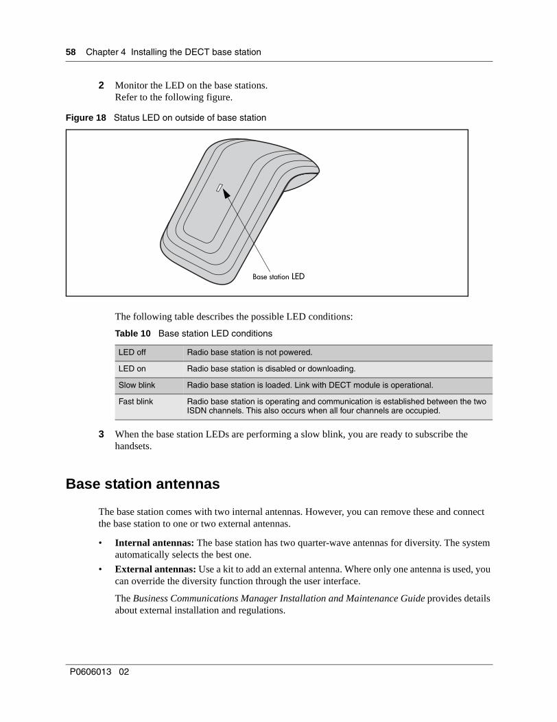
58 Chapter 4 Installing the DECT base station
2 Monitor the LED on the base stations. Refer to the following figure.
Figure 18 Status LED on outside of base station
The following table describes the possible LED conditions:
3 When the base station LEDs are performing a slow blink, you are ready to subscribe the handsets.
Base station antennas
The base station comes with two internal antennas. However, you can remove these and connect the base station to one or two external antennas.
• Internal antennas: The base station has two quarter-wave antennas for diversity. The system automatically selects the best one.
• External antennas: Use a kit to add an external antenna. Where only one antenna is used, you can override the diversity function through the user interface.
The Business Communications Manager Installation and Maintenance Guide provides details about external installation and regulations.
Table 10 Base station LED conditions
LED off Radio base station is not powered.
LED on Radio base station is disabled or downloading.
Slow blink Radio base station is loaded. Link with DECT module is operational.
Fast blink Radio base station is operating and communication is established between the two ISDN channels. This also occurs when all four channels are occupied.
Base station LED
P0606013 02
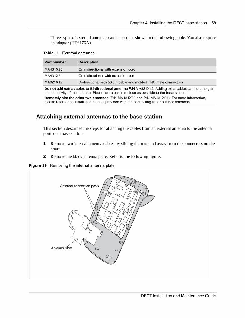
Chapter 4 Installing the DECT base station 59
Three types of external antennas can be used, as shown in the following table. You also require an adapter (HT6176A).
Attaching external antennas to the base station
This section describes the steps for attaching the cables from an external antenna to the antenna ports on a base station.
1 Remove two internal antenna cables by sliding them up and away from the connectors on the board.
2 Remove the black antenna plate. Refer to the following figure.
Figure 19 Removing the internal antenna plate
Table 11 External antennas
Part number Description
MA431X23 Omnidirectional with extension cord
MA431X24 Omnidirectional with extension cord
MA821X12 Bi-directional with 50 cm cable and molded TNC male connectors
Do not add extra cables to Bi-directional antenna P/N MA821X12. Adding extra cables can hurt the gain and directivity of the antenna. Place the antenna as close as possible to the base station.Remotely site the other two antennas (P/N MA431X23 and P/N MA431X24). For more information, please refer to the installation manual provided with the connecting kit for outdoor antennas.
Antenna connection posts
Antenna plate
DECT Installation and Maintenance Guide

60 Chapter 4 Installing the DECT base station
3 Secure cables to external antenna connectors ANT1 and ANT2Use ANT1 if there is only one antenna.
4 Connect the external BNC connector for each antenna.
5 Slide the cover back onto the back panel of the base station.
Refer to “External antenna settings” on page 81 to configure the DECT module to access the external antennas.
P0606013 02
61
Chapter 5Subscribing DECT cordless handsets
This chapter describes how to subscribe the cordless handsets. Subscription allows the handset to communicate with the DECT system. You must have at least one active radio base station to complete the subscription procedure.
This section contains the following information:
• “Process map: subscribing the handsets” on page 62
• “Base station recording status” on page 63
— “DECT Mobile Recording (Handset Subscription) Wizard” on page 63
— “Before you start” on page 63
— “Filling out the Mobile Recording (Handset Subscription) Wizard” on page 64
• “Subscribing DECT cordless handsets” on page 65
• “Handset system features” on page 71
Note: These steps are specific to the C4010 and C4020 handsets. However, all brands of handsets have a similar process. If your handset does not have a similar screen setup to the steps below, refer to the user manual enclosed with your set for specific instructions about entering the registration mode for that set.
DECT Installation and Maintenance Guide

62 Chapter 5 Subscribing DECT cordless handsets
Process map: subscribing the handsets
The following figure provides an overview look at the process of subscribing the handsets.
Figure 20 Process for subscribing the cordless handsets
Set base station to
allow access
Reset the base
station record
Subscribe the handsets
From each handset, enter the base station you want to key the handset to, and enter the handset password. Refer to “DECT Mobile Recording (Handset Subscription) Wizard” on page 63.
Turn off mobile recording for the base station to prevent any unknown handsets from subscribing to the system.Refer to “Resetting the base station” on page 67.
You must set up one base station to allow mobile recording.After you have subscribed the new handsets, ensure that you return the mobile recording field to No. Refer to “Confirming base station readiness” on page 69.
Test the handset
Handset features
Test the handset from various locations to ensure that it works with all the base stations. Refer to “Setup test” on page 71.
Refer to “Handset system features” on page 71 for a list of the main system features available to the handset. Refer to your handset guide for instructions on using the features.
P0606013 02

Chapter 5 Subscribing DECT cordless handsets 63
Base station recording status
Before you can subscribe a handset to the system, the DECT module must be set to receive subscriptions. You can use the DECT Mobile Recording (Handset Subscription) Wizard to do this. You can also use this wizard to turn off recording on the DECT module after you finish subscribing your handsets.
This procedure assumes that you ran the DECT Configuration Wizard, and set up the DN records in the Unified Manager.
DECT Mobile Recording (Handset Subscription) Wizard
Use this wizard to turn on a base station to allow handset subscription.
You can also use this wizard to turn off mobile recording when you have completed the handset subscriptions.
Do not use this wizard until all other DECT module parameters are set.
This section contains:
• “Before you start” on page 63
• “Filling out the Mobile Recording (Handset Subscription) Wizard” on page 64
Before you start
You need to know the following information before you run this wizard:
Note: When one base station is set to on, then all other base stations are off.
• What is the system password?
Default: insta(Password)
• Which base station do you want to enable to allow terminal subscription?
Refer to “Identifying base stations” on page 94 for more information about numbering.
(base station)
6-0 6-1 6-2 6-3
7-0 7-1 7-2 7-3
Note: Pick the base station that is in the most convenient proximity to where the handsets will be subscribed.
DECT Installation and Maintenance Guide
64 Chapter 5 Subscribing DECT cordless handsets
Filling out the Mobile Recording (Handset Subscription) Wizard
Follow these steps to use the wizard:
1 On the first page of the Unified Manager, click the Wizards button.A new page appears, displaying all the wizards that can be used for the Unified Manager.
2 You will be prompted to enter a User Name and Password. You must enter an administrator-level user name and password.A new page appears, displaying all the wizards that can be used for the Unified Manager.
3 Click on the DECT Mobile Recording Wizard button.If the system does not recognize the DECT module, the DECT wizard buttons do not appear. Refer to “Confirming the DECT module” on page 39.
4 On the first page, enter the system password, if there is one.
5 Choose the base station you want to turn on for mobile recording (handset subscription).
6 Click the Next button to move to the next page.
7 If the summary is correct, click the Apply button.
Turning off mobile recording
When you are finished subscribing the handsets, run the wizard again and select None in the Mobile Recording (Handset Subscription) field to turn mobile recording off.
P0606013 02
Chapter 5 Subscribing DECT cordless handsets 65
Subscribing DECT cordless handsets
The procedure in this section describes how to activate the handset to communicate with the Business Communications Manager.
The section contains the following information:
• “Handset buttons” on page 65
• “Subscribing a handset” on page 66
• “Resetting the base station” on page 67
• “Checking handset status” on page 68
• “Confirming base station readiness” on page 69
• “Setup test” on page 71
Ensure that mobile recording has been activated on the DECT module. Refer to “DECT Mobile Recording (Handset Subscription) Wizard” on page 63.
If you attempt to subscribe a handset and the system will not acknowledge it, use the procedure in “Confirming base station readiness” on page 69 to view the state of the base station to which you are trying to subscribe the handset.
Handset buttons
The following table provides a quick preview of the function buttons on the handset. You use these buttons in the procedures in this chapter.
• Use the double-arrow button to scroll through menus.
• Use the right and left arrow buttons to select and confirm menu items displayed at bottom of screen.
• Use the Clear button to clear a display entry.C
DECT Installation and Maintenance Guide

66 Chapter 5 Subscribing DECT cordless handsets
Subscribing a handset
To subscribe a handset, use the handset you want to subscribe, ensure you are within range of the base station you turned on, then follow these steps:
1 Press the left arrow button under Menu until you find Personalize/Last Numbers.
2 Press the right arrow button to open the Personalize menu.
3 Press the double-arrow button until Declare Base appears.
4 Press the left arrow button under Declare.This message appears on the handset. A blinking number indicates the default.
5 Press the left arrow button to confirm the default.Note: 1 is the common default. If another number is blinking, the handset has been assigned to another system. If the user only needs access to this DECT system, you can unsubscribe the 1 position. You can then subscribe the 1 position to the current DECT system. For instructions about how to unsubscribe a handset, refer to “Unsubscribing the handset” on page 122.This message appears on the handset.
6 Enter the handset code using the handset digital keypad.Note: This code is an eight-digit combination of the handset DN and the DECT handset password. Enter the set DN, then add enough digits of the password to make eight digits.For example: If you have five-digit DN 67890 and a password of 12345, the Code would be 67890123.
Main menu
Personalize
Last numbers
Declare Base / number?
12345678 OK
Enter Code
OK
P0606013 02

Chapter 5 Subscribing DECT cordless handsets 67
If this message displays (three seconds), the mobile is registered.
If this message appears, the handset is not subscribed. The display returns to Enter code.
Troubleshooting note: If all your programming appears to be correct, but the handset will not register, try the following:
1 Remove the battery cover and pull the battery out.
2 Place the battery back into the housing and replace the cover.
3 Try subscribing the handset again
Resetting the base station
After you have subscribed or deleted handsets, go back into the Unified Manager and turn off mobile recording for the base station. Use the DECT Mobile Recording (Handset Subscription) wizard to perform this procedure. Refer to “DECT Mobile Recording (Handset Subscription) Wizard” on page 63.
If you are not sure of the state of the base station, follow the procedure in “Confirming base station readiness” on page 69, and check the state of the base station.
Declare Base
OK
Failed.
Retry
DECT Installation and Maintenance Guide

68 Chapter 5 Subscribing DECT cordless handsets
Checking handset status
If you want to confirm that the handsets are entered into the DECT system, you can view the list through the DECT module interface.
Follow these steps to check the handset status:
1 Use Telnet to access the DECT maintenance console. Refer to “Accessing the Maintenance Console” on page 78, if necessary.
2 When the screen says: Connected to <IP address>, press <CTRL p>.The Main maintenance screen appears.
3 From the main menu, type 4 <ENTER> (Open Operation and Administration).
4 Type 6 <ENTER> (Display Statuses)
5 Type 3 <ENTER> Status of Data Links record. The Define Radio Base Station ## DECT appears.
Figure 21 Define Radio Base Station ## DECT screen
6 Telbor status changes from Free to Incomm 1.
7 <ESC m> to view the base station activity.
EQT NO. TYPE DN STATUS NO.LC------------------------------------------------------------------------------AFISER SERVER 010 FREESERVTL SERVER 011 FREEKITAXE SERVER 012 FREESAESAE SERVER 013 FREEMUFACT SERVER 014 FREESERV SERVER 015 FREESERGIC SERVER 016 FREESRVRHM SERVER 017 FREEDEBUG SERVER 018 FREETELBOR SERVER 019 FREEERF SERVER 020 FREE6-0 PLC 80 99900 DISCONNEC6-1 PLC 80 99901 DISCONNEC
Note: card numbers 6-2, 6-3, 7-0, 7-1, 7-2, 7-3 are on page 2 <ESC m>
P0606013 02

Chapter 5 Subscribing DECT cordless handsets 69
Confirming base station readiness
If you turned on base station recording with the Wizard, but you are unable to subscribe handsets to the DECT module, use this procedure to check the state of the base station.
1 Use Telnet to access the DECT maintenance console. Refer to “Accessing the Maintenance Console” on page 78, if necessary.
2 When the screen says: Connected to <IP address>, press <CTRL p>.
3 You will be prompted for a password. (Default=insta)The Main maintenance screen appears.
4 Type 1 <ENTER>. The Telephony Management screen appears.
5 Type 8 <ENTER>. The Wireless Management screen appears.
Figure 22 Wireless Management Menu menu
6 Type 2 <ENTER>. The Wireless:Resources menu appears.
Figure 23 Wireless Resources Menu menu
7 Type 3 <ENTER>.
The Base Station Selection menu appears.
Figure 24 Base Station Selection menu
1 TOPOLOGY2 RESOURCES3 MOBILES
ENTER YOUR CHOICE ..
1 TRUNK GROUP NAMES2 TRUNK GROUP DEFINITION3 BASE STATION ALLOCATION4 BASE STATION DISPLAY5 COVERAGE DISPLAY
ENTER YOUR CHOICE ..
BY EQUIPMENT NUMBER ..OR BY ITS TRUNK GROUP ................OR BY ITS CELL ...................OR BELONG TO AREA ...................
DECT Installation and Maintenance Guide

70 Chapter 5 Subscribing DECT cordless handsets
8 On the first line, type 60 <ENTER>.
These numbers correspond to the RJ45 jacks on the face of the DECT module, from left to right: 73, 71, 72, 70, 63, 62, 61, 60. These connections correspond, in turn, to ports on cards inside the module. All handsets are subscribed to the module and not the card port, therefore, you can subscribe all the handsets through one open port.
The Define Radio Base Station 6-0 DECT Access screen appears. Refer to the following figure.
a New system: Status: disabled, Mobile Recording Allowed: Yes
Existing system: Status: In service; Mobile Recording Allowed: No
b New system: Move your cursor to Status, and use the space bar to find In Service.
The display shows that the base station is downloading. This takes from 30 seconds to 10 minutes, depending on whether the base station needs to update the firmware.
Figure 25 Define Radio Base Station XX DECT screen
c Exit the screen and wait for the base station to complete the download. If you go back into the screen, Status reads: In Service.
9 Subscribe the handset.Refer to “Subscribing a handset” on page 66.
DEFINE RADIO BASE STATION 6-0 DECTRAD. BASE DEFIN. 6-0 DECTSTATUS Disable ..........RAD. BASE TYPE 4 CHAN.BELONGS TO TRUNK GROUP [Trunk Group Name)MOBILE RECORDING ALLOWED YESFRAME TS 0->11 AFFECTATION 111111111111TS NO MODIFICATION ..0->9 FREQUENCY ALLOCATION 111111111111- FREQUENCY NO MODIFANTENNA SELCTION AUTOMATICSYNCHRONIZATION VIA BIT FRAME SDISTANCE FROM MASTER BS D<100 METERESTYPE OF BUS SHORT
P0606013 02
Chapter 5 Subscribing DECT cordless handsets 71
Setup test
When you have completed handset subscription, or any change to the DECT system, check that the system is operational.
1 Check that the base station LED indicates that the module is in service (LED blinks slowly). If the LED is on but not blinking, the module is downloading new information from the Business Communications Manager. This can take as long as 10 minutes.
2 Check the system operation.
Perform the following operations in order to test the DECT service.
a Locate four handsets near separate base stations.
b Dial each set from another cordless handset.
c Ensure that the handsets are able to talk to each other.
d Check the system for general operation. Refer to the following table.
Handset system features
This section lists the features that the handset supports and any feature-specific information in the following areas:
• “Hunt groups” on page 72
• “Message Waiting Indicator (MWI)” on page 72
• “Twinning features” on page 73
• “CallPilot programming” on page 73
• “Auto-answer issues” on page 73
• “Receiving a page” on page 74
• “Roaming” on page 74
The cordless handset supports the following features:
• twin to a fixed set to allow remote reception of calls
• make and receive calls from the handset, within the range of the system the handset is subscribed to as an independent set
• transfer and conference calls from and to the handset
Table 12 Troubleshooting the preliminary operations
Problem Solution
Communication with the handset is interrupted while moving around between base stations,
Re-establish the communication from an operational base station, then continue checking the other base stations.
Communication cannot be established from a radio base station:
Check the configurations
DECT Installation and Maintenance Guide

72 Chapter 5 Subscribing DECT cordless handsets
• display an internal caller by name, and an external caller by number or name, depending on how the external line is set up.
• query the voice mail system using the mail extension or the Message Waiting button
• call forward calls, and cancel call forward, to another set, to voice mail, or to an external number
• determine when a call gets forwarded: all calls, on busy, or if call is not answered
• make a second call while a call is in progress
• shuttle between two calls
• roam between DECT cells (handset-specific)
• call waiting indication if a call is received while the handset is busy on another call.
• enbloc and overlap dialing is supported, as well as memory dialing
Hunt groups
If more than four handsets are deployed in a hunt group, ensure that no more than four are configured to the same base station. Since a base station can only handle four calls at once, if more than four handsets in a hunt group are localised on the same base station, some DECT handsets may not ring simultaneously, if at all. If more than four handsets are required within a hunt group, ensure deployment is correctly adjusted to ensure radio coverage avoids handsets with the same radio signal level on multiple handsets.
Message Waiting Indicator (MWI)
DECT handsets have the ability to access mailboxes for both internal, stand-alone systems, and external voice mail systems accessed over a private network.
To initialize and set up the connection, you must directly dial the voice mail system through the handset and set up or change the account as required. Your voice mail administrator provides the number and your account access.
Note: DECT handsets can only access voice mailboxes and the associated MWI for new messages. They do not support other voicemail functions, Call Center features, Attendant Console,
Note: This feature uses two of the available eight lines per DECT when the handset is the primary and the other two calls are non-DECT calls.
Conference calls originated from the handset are limited to one hour.
Note: The third call into a cordless handset receives a busy tone, depending on the type of call (internal/external), the type of line, and the DND on busy setting. If the portable user cannot be located, call capture rules apply.
Note: Refer to the Programming Operations Guide to configure these features for each handset DN.
P0606013 02
Chapter 5 Subscribing DECT cordless handsets 73
TAPI applications, or CTE applications. The Business Communications Manager only supports these features on the Symbol© NetVision© wireless handsets.
Programming the MWI lamp button
When a message occurs for a handset, the MWI lamp on the handset lights.
This button must be programmed with the voice mail access code so the user can press the button and be automatically connected to the voice mail system. The voice mail field must be set to *65 to allow the MWI feature (*65) to work.
To set up the feature, on the handset:
• Go to Menu/Personalize/VoiceMail/VoiceMail Nr and enter *65.
• Go to Menu/Personalize/VoiceMail/Access Nr and ensure that the field is blank.
When all messages have been retrieved, the MWI button lamp goes off. The user then presses the MWI button again to release the call and the user hears a reorder tone.
Twinning features
These are the features and anomalies that occur when you twin a DECT handset to a desk telephone, or vice versa.
Ringback issues occur if the DECT handsets do not have Call Forward No Answer configured.
CallPilot programming
If CallPilot is the voice mail system being used, ensure that the administrator includes the handset DN as the alternate DN for the desk set with which the DECT handset is twinned.
If the DECT handset is being used as a stand-alone set, then the CallPilot set up is the same as for any other Business Communications Manager set.
Auto-answer issues (security issue)
If your handset is set to Auto-Answer, you can be opening yourself to security issues. If your cordless DECT handset is set to Auto-Answer, your handset opens the line to the caller, whether you activate the handset or not. This occurs even if your voicemail is set to automatically go to voice mail after a number of unanswered rings,
Refer to your handset documentation for the steps required to turn Auto-Answer off on any handsets where this feature can be a concern.
Note: Mailbox access is the only Business Communications Manager voice mail application that is accessible from the handset.
DECT Installation and Maintenance Guide
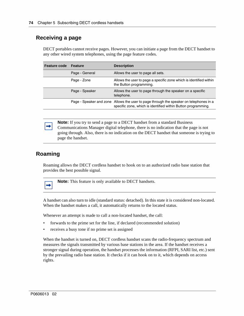
74 Chapter 5 Subscribing DECT cordless handsets
Receiving a page
DECT portables cannot receive pages. However, you can initiate a page from the DECT handset to any other wired system telephones, using the page feature codes.
Roaming
Roaming allows the DECT cordless handset to hook on to an authorized radio base station that provides the best possible signal.
A handset can also turn to idle (standard status: detached). In this state it is considered non-located. When the handset makes a call, it automatically returns to the located status.
Whenever an attempt is made to call a non-located handset, the call:
• forwards to the prime set for the line, if declared (recommended solution)
• receives a busy tone if no prime set is assigned
When the handset is turned on, DECT cordless handset scans the radio-frequency spectrum and measures the signals transmitted by various base stations in the area. If the handset receives a stronger signal during operation, the handset processes the information (RFPI, SARI list, etc.) sent by the prevailing radio base station. It checks if it can hook on to it, which depends on access rights.
Feature code Feature Description
Page - General Allows the user to page all sets.
Page - Zone Allows the user to page a specific zone which is identified within the Button programming.
Page - Speaker Allows the user to page through the speaker on a specific telephone.
Page - Speaker and zone Allows the user to page through the speaker on telephones in a specific zone, which is identified within Button programming.
Note: If you try to send a page to a DECT handset from a standard Business Communications Manager digital telephone, there is no indication that the page is not going through. Also, there is no indication on the DECT handset that someone is trying to page the handset.
Note: This feature is only available to DECT handsets.
P0606013 02
Chapter 5 Subscribing DECT cordless handsets 75
The following occurs:
• If the access is permitted, the handset compares the radio base station RFPI to the LAL value, which is generated upon registration. It uses this calculation to determine if the radio base station belongs to a new roaming area (cell).
• If the comparison indicates that the location area has changed (with no communication established), the handset sends a roaming request to the radio base station. If the radio base station accepts, the handset remains synchronized to this base station for on-going analysis of the signaling channel (cell selection). At this stage, the handset is attached to this radio base station.
With communication established, the handset initializes an external hand-over in order to keep the communication established when the radio base station changes.
Roaming on outgoing calls
Roaming is activated from the handset.
A handset sends a request for roaming to the DECT module in the following circumstances:
• when the registration procedure completes
• whenever the handset is turned on
• when external hand-over occurs
• whenever the handset changes cells
The handset uses the exchange protocol on the radio interface to understand that the stronger signal it is now connecting to belongs to a roaming zone. Further, the signal indicates it is a different base station from the one the handset was attached to.
The DECT module updates its routing tables and stores the (site-based) number of the cell occupied by this handset.
Direct Inward Roaming
Incoming calls route to this handset when its site and cell numbers are specified.
Note: In case of access restrictions, the DECT module can refuse a cell change. If so, the handset waits a certain time before making new attempts.
DECT Installation and Maintenance Guide

76 Chapter 5 Subscribing DECT cordless handsets
P0606013 02

77
Chapter 6Programming DECT module defaults
Use the DECT Configuration Wizard to set up the DECT module. However, if you need to check any of the DECT module parameters after the initial configuration of the module, you can go to individual records on the module to check or change settings. For instance, if you want to assign a new password.
This section describes the DECT interface menus that define the basic system parameters for the DECT module. A new DECT module comes with a set of defaults. Use these menus to check that the defaults are set correctly for your system or adjust the settings, as required.
The information is contained in the following sections:
• “Accessing the Maintenance Console” on page 78
• “System Management” on page 79
• “External antenna settings” on page 81
You can access these menus through Launch Maintenance Console on the Unified Manager Tools menu when you select a DECT module record.
The following figure provides a map of the default settings you need to check.
Figure 26 DECT interface, system management
Launch Maintenance
Console
Checkpasswords
Confirm card ports
Check language
setting
Check the system and handset passwords.Refer to “DECT and handset passwords” on page 79.
Confirm that the interface is in the language you require.Refer to “Language Management” on page 80.
Confirm that the DECT module C8 card is set up correctly.Refer to “Card Management” on page 81.
Enter the DECT interface through the Unified Manager Launch Maintenance Console.Refer to “Accessing the Maintenance Console” on page 78.
DECT Installation and Maintenance Guide

78 Chapter 6 Programming DECT module defaults
Accessing the Maintenance ConsoleThe DECT module maintenance console text-based menus are accessed using Telnet or a VT100 emulation program if you are connecting through the serial port of the Business Communications Manager.
To access the DECT module interface using Telnet, use the maintenance console application in the Unified Manager. These steps describe the process of launching the application.
1 Enter the Unified Manager.
2 Click Resources, DECT.
3 Choose the Maintenance Selection tab.
4 Ensure that the DECT module has been chosen.
5 Under the Tools menu, click Launch Maintenance Console.
6 When the screen says: Connected to <IP address>, press <CTRL p>.
7 You will be prompted to enter a password. (Default=insta)
8 Type 10.The main DECT maintenance menu appears.
Figure 27 Main DECT maintenance menu
1 TELEPHONY MANAGEMENT2 DATA MANAGEMENT3 SYSTEM MANAGEMENT4 OPERATION ADMINISTRATION5 INSTALLER DATA
ENTER YOUR CHOICE ..
P0606013 02
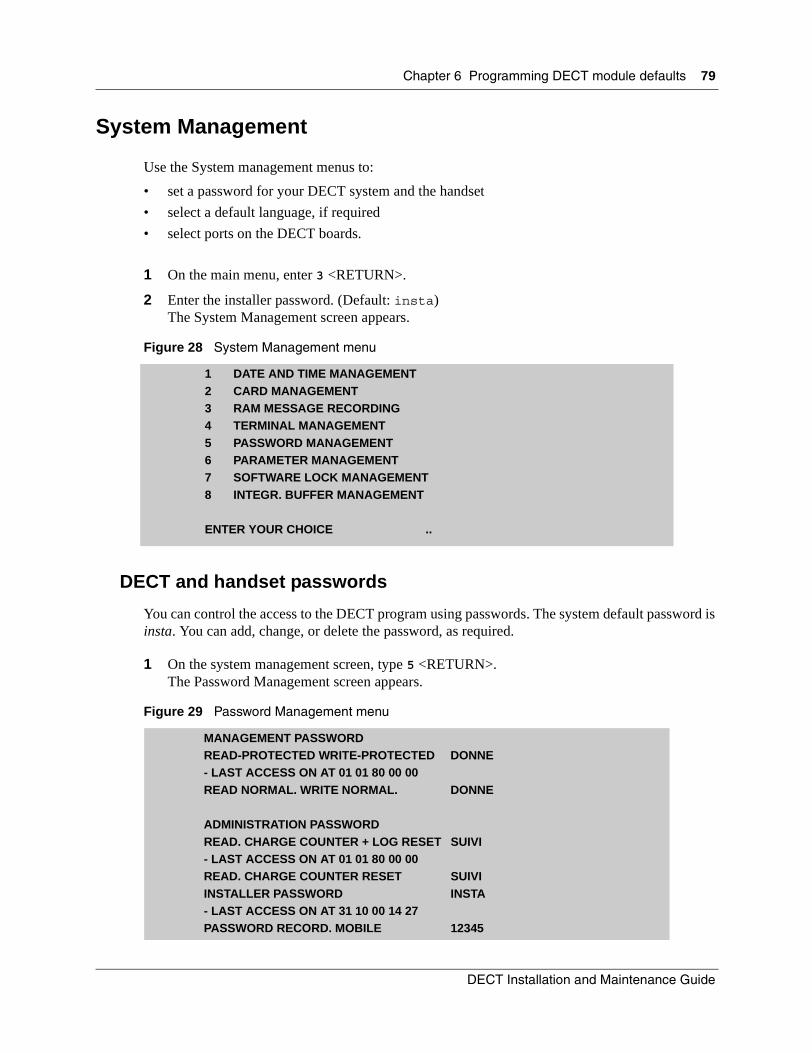
Chapter 6 Programming DECT module defaults 79
System Management
Use the System management menus to:
• set a password for your DECT system and the handset
• select a default language, if required
• select ports on the DECT boards.
1 On the main menu, enter 3 <RETURN>.
2 Enter the installer password. (Default: insta)The System Management screen appears.
Figure 28 System Management menu
DECT and handset passwords
You can control the access to the DECT program using passwords. The system default password is insta. You can add, change, or delete the password, as required.
1 On the system management screen, type 5 <RETURN>.The Password Management screen appears.
Figure 29 Password Management menu
1 DATE AND TIME MANAGEMENT2 CARD MANAGEMENT3 RAM MESSAGE RECORDING4 TERMINAL MANAGEMENT5 PASSWORD MANAGEMENT6 PARAMETER MANAGEMENT7 SOFTWARE LOCK MANAGEMENT8 INTEGR. BUFFER MANAGEMENT
ENTER YOUR CHOICE ..
MANAGEMENT PASSWORDREAD-PROTECTED WRITE-PROTECTED DONNE- LAST ACCESS ON AT 01 01 80 00 00READ NORMAL. WRITE NORMAL. DONNE
ADMINISTRATION PASSWORDREAD. CHARGE COUNTER + LOG RESET SUIVI- LAST ACCESS ON AT 01 01 80 00 00READ. CHARGE COUNTER RESET SUIVIINSTALLER PASSWORD INSTA- LAST ACCESS ON AT 31 10 00 14 27PASSWORD RECORD. MOBILE 12345
DECT Installation and Maintenance Guide

80 Chapter 6 Programming DECT module defaults
2 On the Installer Password line, enter a new password, or leave it blank.
3 On the Password Record. Mobile line, enter a registration number.This number is used as part of the registration key for the handset.
4 Press <CTRL j> to return to the System Management menu.
Language Management
If the menu system is not in the language you want, you can change the default language. If the menu is in the language you want, skip this section.
1 On the System Management menu, type 6 <RETURN> (Parameter Management).The Parameter Management screen appears.
Figure 30 Parameter Management menu
2 Use the space bar to select the correct language.
3 Press <CTRL j> to return to the System Management menu.
Note: If you change the DECT Administrator password, you must delete the scheduled time synch task. To delete the task, click the Schedule link on the BRU window to display the task, then click the Delete button.
After the task is deleted, you need to re-establish the time synch schedule. For details, refer to “Setting up the module Time Synch” on page 50.
MULTI-COMPANY MANAGEMENT NOMULTI-SITE MANAGEMENT NOOPERATOR GROUP AUDIT ACTIVATED NOTYPE OF THE WIRELESS MANAGEMENT DECTCONSOLE TIME-OUT (SECONDS) 600CURRENT LANGUAGE LANGUAGE 2INSTALL. NAME MC 6501 C ..........................
NUMBER OF RECORDS (current) (requested)- TELEPHONY TYPE 356 356- DATA TYPE 10 10- SERVICE TYPE 10 10- MONITORING TYPE 24 24
P0606013 02
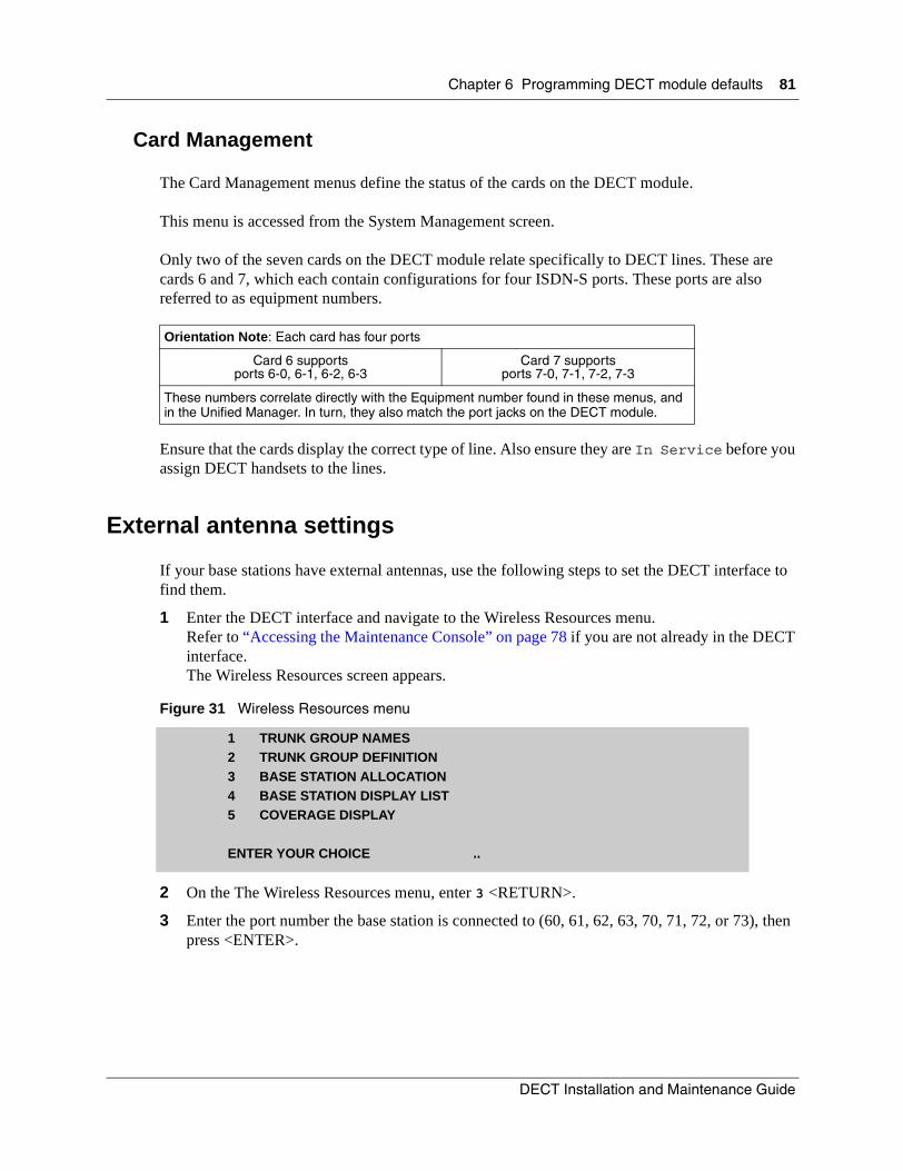
Chapter 6 Programming DECT module defaults 81
Card Management
The Card Management menus define the status of the cards on the DECT module.
This menu is accessed from the System Management screen.
Only two of the seven cards on the DECT module relate specifically to DECT lines. These are cards 6 and 7, which each contain configurations for four ISDN-S ports. These ports are also referred to as equipment numbers.
Ensure that the cards display the correct type of line. Also ensure they are In Service before you assign DECT handsets to the lines.
External antenna settings
If your base stations have external antennas, use the following steps to set the DECT interface to find them.
1 Enter the DECT interface and navigate to the Wireless Resources menu. Refer to “Accessing the Maintenance Console” on page 78 if you are not already in the DECT interface.The Wireless Resources screen appears.
Figure 31 Wireless Resources menu
2 On the The Wireless Resources menu, enter 3 <RETURN>.
3 Enter the port number the base station is connected to (60, 61, 62, 63, 70, 71, 72, or 73), then press <ENTER>.
Orientation Note: Each card has four ports
Card 6 supports ports 6-0, 6-1, 6-2, 6-3
Card 7 supports ports 7-0, 7-1, 7-2, 7-3
These numbers correlate directly with the Equipment number found in these menus, and in the Unified Manager. In turn, they also match the port jacks on the DECT module.
1 TRUNK GROUP NAMES2 TRUNK GROUP DEFINITION3 BASE STATION ALLOCATION4 BASE STATION DISPLAY LIST5 COVERAGE DISPLAY
ENTER YOUR CHOICE ..
DECT Installation and Maintenance Guide
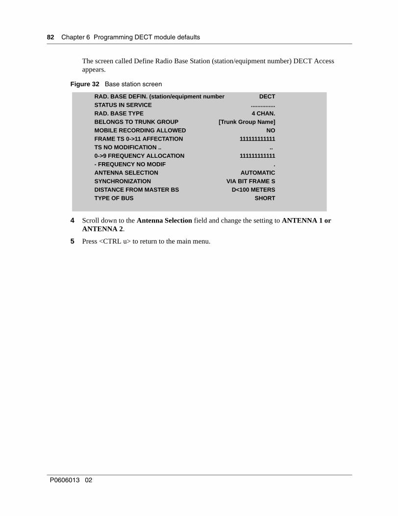
82 Chapter 6 Programming DECT module defaults
The screen called Define Radio Base Station (station/equipment number) DECT Access appears.
Figure 32 Base station screen
4 Scroll down to the Antenna Selection field and change the setting to ANTENNA 1 or ANTENNA 2.
5 Press <CTRL u> to return to the main menu.
RAD. BASE DEFIN. (station/equipment number DECTSTATUS IN SERVICE ...............RAD. BASE TYPE 4 CHAN.BELONGS TO TRUNK GROUP [Trunk Group Name]MOBILE RECORDING ALLOWED NOFRAME TS 0->11 AFFECTATION 111111111111TS NO MODIFICATION .. ..0->9 FREQUENCY ALLOCATION 111111111111- FREQUENCY NO MODIF .ANTENNA SELECTION AUTOMATICSYNCHRONIZATION VIA BIT FRAME SDISTANCE FROM MASTER BS D<100 METERSTYPE OF BUS SHORT
P0606013 02
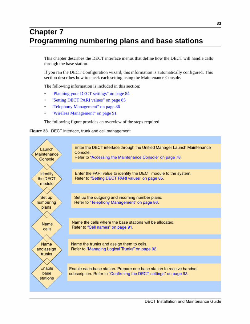
83
Chapter 7Programming numbering plans and base stations
This chapter describes the DECT interface menus that define how the DECT will handle calls through the base station.
If you ran the DECT Configuration wizard, this information is automatically configured. This section describes how to check each setting using the Maintenance Console.
The following information is included in this section:
• “Planning your DECT settings” on page 84
• “Setting DECT PARI values” on page 85
• “Telephony Management” on page 86
• “Wireless Management” on page 91
The following figure provides an overview of the steps required.
Figure 33 DECT interface, trunk and cell management
Launch Maintenance
Console
Identify the DECT module
Name cells
Set up numbering
plans
Enter the PARI value to identify the DECT module to the system. Refer to “Setting DECT PARI values” on page 85.
Set up the outgoing and incoming number plans.Refer to “Telephony Management” on page 86.
Name the cells where the base stations will be allocated.Refer to “Cell names” on page 91.
Enter the DECT interface through the Unified Manager Launch Maintenance Console.Refer to “Accessing the Maintenance Console” on page 78.
Name and assign
trunks
Enable base
stations
Name the trunks and assign them to cells.Refer to “Managing Logical Trunks” on page 92.
Enable each base station. Prepare one base station to receive handset subscription. Refer to “Confirming the DECT settings” on page 93.
DECT Installation and Maintenance Guide

84 Chapter 7 Programming numbering plans and base stations
Planning your DECT settings
To plan what you need to enter, refer to your DECT deployment plan.
You also require access to the Business Communications Manager information.
Use the following table to identify the cells, trunks and base station allocations.
Use the following table to identify the numbering plan entries for your system.
Table 13 Identifying cell, trunk and base station assignments
Cells Trunks assigned Base stations
Example:Cell CGCL22
two trunks are assigned60CGTR22, 61CGTR22
connected to these base stationsbase station 1, base station 2
Table 14 Identify the outgoing and incoming numbering codes for your system
DN length =
Outgoing DNs and codes Incoming DNs
P0606013 02
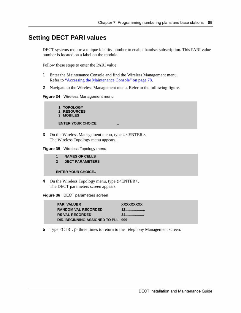
Chapter 7 Programming numbering plans and base stations 85
Setting DECT PARI values
DECT systems require a unique identity number to enable handset subscription. This PARI value number is located on a label on the module.
Follow these steps to enter the PARI value:
1 Enter the Maintenance Console and find the Wireless Management menu.Refer to “Accessing the Maintenance Console” on page 78.
2 Navigate to the Wireless Management menu. Refer to the following figure.
Figure 34 Wireless Management menu
3 On the Wireless Management menu, type 1 <ENTER>.The Wireless Topology menu appears..
Figure 35 Wireless Topology menu
4 On the Wireless Topology menu, type 2<ENTER>.The DECT parameters screen appears.
Figure 36 DECT parameters screen
5 Type <CTRL j> three times to return to the Telephony Management screen.
1 TOPOLOGY2 RESOURCES3 MOBILES
ENTER YOUR CHOICE ..
1 NAMES OF CELLS2 DECT PARAMETERS
ENTER YOUR CHOICE..
PARI VALUE 0 XXXXXXXXXRANDOM VAL RECORDED 12....................RS VAL RECORDED 34...................DIR. BEGINNING ASSIGNED TO PLL 999
DECT Installation and Maintenance Guide
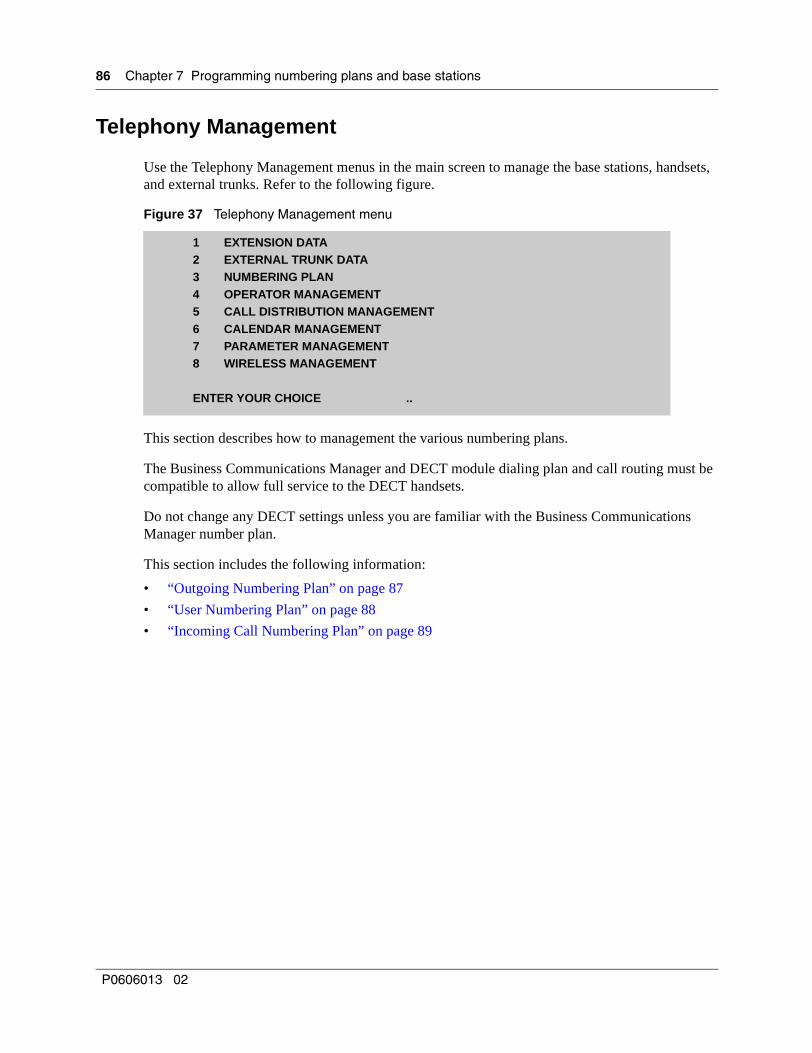
86 Chapter 7 Programming numbering plans and base stations
Telephony Management
Use the Telephony Management menus in the main screen to manage the base stations, handsets, and external trunks. Refer to the following figure.
Figure 37 Telephony Management menu
This section describes how to management the various numbering plans.
The Business Communications Manager and DECT module dialing plan and call routing must be compatible to allow full service to the DECT handsets.
Do not change any DECT settings unless you are familiar with the Business Communications Manager number plan.
This section includes the following information:
• “Outgoing Numbering Plan” on page 87
• “User Numbering Plan” on page 88
• “Incoming Call Numbering Plan” on page 89
1 EXTENSION DATA2 EXTERNAL TRUNK DATA3 NUMBERING PLAN4 OPERATOR MANAGEMENT5 CALL DISTRIBUTION MANAGEMENT6 CALENDAR MANAGEMENT7 PARAMETER MANAGEMENT8 WIRELESS MANAGEMENT
ENTER YOUR CHOICE ..
P0606013 02
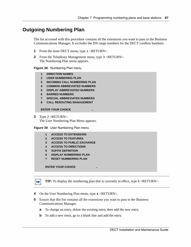
Chapter 7 Programming numbering plans and base stations 87
Outgoing Numbering Plan
The list accessed with this procedure contains all the extensions you want to pass to the Business Communications Manager. It excludes the DN range numbers for the DECT cordless handsets.
1 From the main DECT menu, type 1 <RETURN>.
2 From the Telephony Management menu, type 3 <RETURN>.The Numbering Plan menu appears.
Figure 38 Numbering Plan menu
3 Type 2 <RETURN>.The User Numbering Plan Menu appears.
Figure 39 User Numbering Plan menu
4 On the User Numbering Plan menu, type 4 <RETURN>.
5 Ensure that this list contains all the extensions you want to pass to the Business Communications Manager.
a To change an entry, delete the existing entry, then add the new entry.
b To add a new entry, go to a blank line and add the entry.
TIP: To display the numbering plan that is currently in effect, type 6 <RETURN>.
1 DIRECTION NAMES2 USER NUMBERING PLAN3 INCOMING CALL NUMBERING PLAN4 COMMON ABBREVIATED NUMBERS5 DISPLAY ABBREVIATED NUMBERS6 BARRED NUMBERS7 SPECIAL ABBREVIATED NUMBERS8 CALL REROUTING MANAGEMENT
ENTER YOUR CHOICE ..
1 ACCESS TO EXTENSIONS2 ACCESS TO FEATURES3 ACCESS TO PUBLIC EXCHANGE4 ACCESS TO DIRECTIONS5 SUFFIX DEFINITION6 DISPLAY NUMBERING PLAN7 RESET NUMBERING PLAN
ENTER YOUR CHOICE ..
DECT Installation and Maintenance Guide

88 Chapter 7 Programming numbering plans and base stations
Here are some examples:
— 9(*) = user dials 9, then any number of digits after (external line)
— 0(1) = user dials 0 (operator)
— 5(5) = user dials a five-digit extension starting with 5. (50000 to 59999)
Figure 40 DECT directory numbers
6 Press <CTRL j> to return to the Users Number Plan.
User Numbering Plan
The User numbering plan lists the range of handset extensions. This list provides handset-to-handset access on the network.
Follow these steps to add or change the User Numbering Plan entries:
1 On the User Numbering Plan menu, type 1 <RETURN> (Access to Extensions).The Local Dialing list appears.
Figure 41 Local Dialing List
2 Ensure that Number of Digits field entry corresponds to the DN length used by your Business Communications Manager system.
a To change the number, delete the current Number of Digits entry using the <Delete> key on your keyboard.
b Enter the new number, then press <RETURN>.
3 Range 1-12: enter the ranges of handset extensions. This allows you to access other handsets on the network from your handset.
a Delete any existing range numbers if they are incorrect.
b Add the new range(s) of DNs (597-624).
Note: This list excludes the DN range for the DECT handsets.
SPECIFIC NUMBERS1 9(*)........................2 0(1).......................3 5(5).......................etc. ..............................
NUMBER OF DIGITS 3NUMBER OF DIGITS TO DELETE 0
RANGE 1 597-9RANGE 2 66-1
RANGE 3 620-4etc.
P0606013 02

Chapter 7 Programming numbering plans and base stations 89
Syntax: The syntax you use to enter numbers depends on the entry in the Number of Digits line. Refer to the following table for the default ranges. Adjust the numbers to fit the DN range on your own system.
Example: If you specified 3 for the number of digits, enter the numbers as follows:
• To enter the range 500-529, enter 50-2 for Range 1
• To enter 530 to 532, enter 530-2
4 Press <CTRL j> until you return to the Telephony Management screen.
Incoming Call Numbering Plan
The list you access with this procedure determines what calls to the handset are allowed. Ensure that the Default Number of Digits in this list is the same as the DN length entered in your Business Communications Manager and the DECT local dialing list.
1 From the Numbering Plan menu, type 3 <RETURN>.The Incoming Call Numbering Plan menu appears.
Figure 42 Incoming Call Numbering Plan menu
2 Type 1 <RETURN> (Internal Dialing).The Incoming plan: internal numb. list appears.
Table 15 DECT defaults:
Default Range (597-624) Range 3-digit entry
597-599 Range 1 597-9
600-619 Range 2 60-1
620-624 Range 3 620-4
1 INTERNAL DIALING2 ACCESS TO PUBLIC EXCHANGE3 ACCESS TO DIRECTIONS4 DID CORPORATE NUMBERS5 DISPLAY NUMBERING PLAN6 RESET NUMBERING PLAN
ENTER YOUR CHOICE ..
DECT Installation and Maintenance Guide
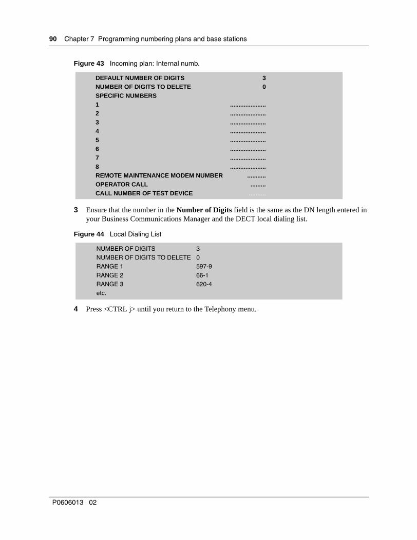
90 Chapter 7 Programming numbering plans and base stations
Figure 43 Incoming plan: Internal numb.
3 Ensure that the number in the Number of Digits field is the same as the DN length entered in your Business Communications Manager and the DECT local dialing list.
Figure 44 Local Dialing List
4 Press <CTRL j> until you return to the Telephony menu.
DEFAULT NUMBER OF DIGITS 3NUMBER OF DIGITS TO DELETE 0SPECIFIC NUMBERS1 .....................2 .....................3 .....................4 .....................5 .....................6 .....................7 .....................8 .....................REMOTE MAINTENANCE MODEM NUMBER ...........OPERATOR CALL .........CALL NUMBER OF TEST DEVICE ..........
NUMBER OF DIGITS 3NUMBER OF DIGITS TO DELETE 0RANGE 1 597-9
RANGE 2 66-1RANGE 3 620-4etc.
P0606013 02

Chapter 7 Programming numbering plans and base stations 91
Wireless Management
Manage the cells and virtual trunks through the Telephony Management/Wireless Management/Topology menu.
This section contains the following information:
• “Cell names” on page 91
• “Managing Logical Trunks” on page 92
Cell names
Each base station is part of a cell. Use this procedure to identify the cells in your system.
1 At the main menu, type 1 <ENTER>.
2 On the Telephony Management screen, type 8 <Enter> to access the Wireless Management menu.The Wireless Management menu appears.
Figure 45 Wireless Management menu
3 At the Wireless Management menu, type 1 <ENTER>.The Wireless Topology menu appears.
Figure 46 Wireless Topology menu
4 On the Wireless Topology menu, type 1 <ENTER> to access the Names of Cells screen.
5 Use the <TAB> key to move down the line to the cell names.
6 Enter a name for the cell you want to add. Note: Assign all your base stations to one cell name.
7 Type <CTRL j> to return to the Wireless Topology menu.
1 TOPOLOGY2 RESOURCES3 MOBILES
ENTER YOUR CHOICE ..
1 NAMES OF CELLS2 DECT PARAMETERS
ENTER YOUR CHOICE..
DECT Installation and Maintenance Guide

92 Chapter 7 Programming numbering plans and base stations
Managing Logical Trunks
Use the Wireless Management Resources menus to:
• name logical trunk groups
• define how the trunk groups will operate
Follow these steps to access the screen where you can change the logical trunks settings:
1 At the Wireless Management menu, type 2 <ENTER> to access the Wireless Resources menu.
Figure 47 Wireless Resources menu
2 On the Wireless Resources screen, type 1 <ENTER>.The Trunk Group Names screen appears.
3 Enter names for each logical trunk group.
Note: You must associate the cells with a logical trunk group name and relate this to a base station name. This procedure sets the communication path for the mobile handset within the DECT module.Define a trunk group for each base station. Use the tab key to move through the menu.
4 Press <CTRL j> to return to the Wireless Resources menu.
5 On the Wireless Resources menu, type 2 <ENTER>.
6 Enter a trunk group name. Enter a name or press the space bar to scroll through the list to pick a name.
7 Press <RETURN>.
8 Enter the cell name, or use the space bar to scroll through the list to pick a name.
LOCATED IN CELL............................
9 Press <RETURN>.
10 Press <CTRL u> to return to the main menu.
1 TRUNK GROUP NAMES2 TRUNK GROUP DEFINITION3 BASE STATION ALLOCATION4 BASE STATION DISPLAY LIST5 COVERAGE DISPLAY
ENTER YOUR CHOICE ..
P0606013 02

93
Chapter 8Programming DECT handset records
This section describes how to use the Maintenance Console to access the DECT interface to setup the base station record and to confirm the handset (mobile) numbers. It also describes how to add DNs for handsets to the DECT record. You must use this process if you add DNs after you run the DECT Configuration Wizard.
This information is contained in the following sections:
• “Confirming the DECT settings” on page 93
• “Mobile Management” on page 96
Confirming the DECT settings
Verify in the DECT module interface that the handsets are set up correctly.
If you do not know how to access the DECT interface, refer to “Accessing the Maintenance Console” on page 78.
1 From the main DECT interface menu, type 1 <ENTER>.The Telephony Management menu appears.
Figure 48 Telephony Management menu
2 Type 8 <ENTER>.The Wireless Management menu appears. The following figure displays the start menu for the processes that follow.
Figure 49 Wireless Management menu
1 EXTENSION DATA2 EXTERNAL TRUNK DATA3 NUMBERING PLAN4 OPERATOR MANAGEMENT5 CALL DISTRIBUTION MANAGEMENT6 CALENDAR MANAGEMENT7 PARAMETER MANAGEMENT8 WIRELESS MANAGEMENT
ENTER YOUR CHOICE ..
1 TOPOLOGY2 RESOURCES3 MOBILES
ENTER YOUR CHOICE ..
DECT Installation and Maintenance Guide
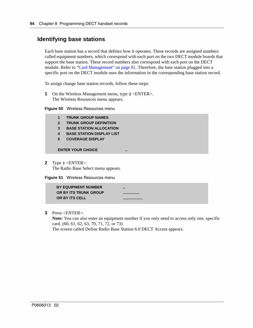
94 Chapter 8 Programming DECT handset records
Identifying base stations
Each base station has a record that defines how it operates. These records are assigned numbers called equipment numbers, which correspond with each port on the two DECT module boards that support the base station. These record numbers also correspond with each port on the DECT module. Refer to “Card Management” on page 81. Therefore, the base station plugged into a specific port on the DECT module uses the information in the corresponding base station record.
To assign change base station records, follow these steps:
1 On the Wireless Management menu, type 2 <ENTER>.The Wireless Resources menu appears.
Figure 50 Wireless Resources menu
2 Type 3 <ENTER>.The Radio Base Select menu appears.
Figure 51 Wireless Resources menu
3 Press <ENTER>.Note: You can also enter an equipment number if you only need to access only one, specific card. (60, 61, 62, 63, 70, 71, 72, or 73)The screen called Define Radio Base Station 6.0 DECT Access appears.
1 TRUNK GROUP NAMES2 TRUNK GROUP DEFINITION3 BASE STATION ALLOCATION4 BASE STATION DISPLAY LIST5 COVERAGE DISPLAY
ENTER YOUR CHOICE ..
BY EQUIPMENT NUMBER ..OR BY ITS TRUNK GROUP ................OR BY ITS CELL ...................
P0606013 02

Chapter 8 Programming DECT handset records 95
Figure 52 Base station screen
4 When you first install the base stations, this record shows the Status to be Disabled.
a Ensure that the Status is Disabled.
b Go down to Mobile Recording Allowed and set it to YES.
Warning: Set Mobile Recording Allowed to YES only for the period when you will be subscribing new handsets. At all other times, ensure this entry is set to No to prevent illegal entry of unauthorized handsets. You must disable the base station before you turn this setting on or off.
c Ensure that the screen displays the following parameters:
• A Trunk Group has been specified
• Rad. Base type is set to 4 CHAN
• Synchronization is set to VIA BIT M FRAME S
d Go back to Status and put the base station back in service.The LED on the base station goes solid while it checks with the DECT module for any updates. After the LED starts blinking, the base station is back in service. To check, press <CTRL j>, then return to the base station record.
5 Press <ESC n> to go to the next record.
6 Ensure that the screen displays the following parameters:
• A Trunk Group has been specified
• Rad. Base type is set to 4 CHAN
• Synchronization is set to VIA BIT M FRAME S
• Mobile Recording Allowed is set to NO.
7 Go to the Status line and press the space bar to put the base station record in service.The LED on the base station goes solid while it checks with the DECT module for any updates. After the LED starts blinking, the base station is back in service. To check, press <CTRL j>, then return to the base station record.
RAD. BASE DEFIN. (station/equipment number DECTSTATUS IN SERVICERAD. BASE TYPE 4 CHAN.BELONGS TO TRUNK GROUP [Trunk Group Name]MOBILE RECORDING ALLOWED NOFRAME TS 0->11 AFFECTATION 111111111111TS NO MODIFICATION ..0->9 FREQUENCY ALLOCATION 111111111111- FREQUENCY NO MODIFANTENNA SELECTION AUTOMATICSYNCHRONIZATION VIA BIT M FRAME SDISTANCE FROM MASTER BS D<100 METERSTYPE OF BUS SHORT
DECT Installation and Maintenance Guide

96 Chapter 8 Programming DECT handset records
8 Repeat steps 5 to 7 for the rest of the base stations.
9 Press <CTRL j> until the Wireless Management menu appears.
Mobile Management
The DECT module interface handset numbers must match the DNs found under the Unified Manager navigation tree Services, Telephony Services, System DNs, All ISDN/DECT DNs. To check this, or to change the DNs on the DECT interface, access the module through the Unified Manager using the Launch Maintenance Console command.
If you do not know how to access the DECT interface, refer to “Accessing the Maintenance Console” on page 78.
Note:Default DECT module DNs:
New Business Communications Manager: 597-624
Upgraded 2.0 Business Communications Manager: 501-532
These defaults assume a system with a three-digit DN structure, and a Start DN of 221. If your system is different, use these numbers as guidelines to find the defaults to your system.
DECT modules can only use DNs from three to six digits long.
Warning: Resetting system DN lengths
If you changed the DN length for your system after a DECT module has been installed, you will no longer be able to record mobiles to the DECT module. You need to reset the DECT module: Resources/DECT/Tools menu/Reset Selected MBM. Then go into the module interface and confirm that the DECT-based DNs still match those on the Unified Manager.
P0606013 02
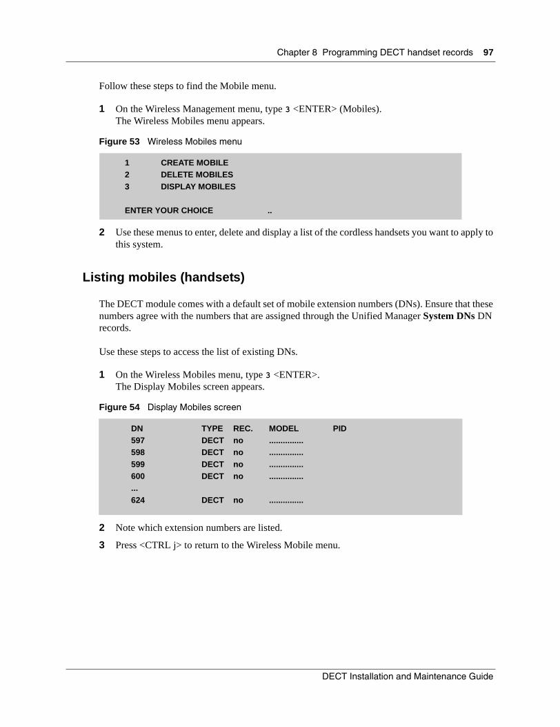
Chapter 8 Programming DECT handset records 97
Follow these steps to find the Mobile menu.
1 On the Wireless Management menu, type 3 <ENTER> (Mobiles).The Wireless Mobiles menu appears.
Figure 53 Wireless Mobiles menu
2 Use these menus to enter, delete and display a list of the cordless handsets you want to apply to this system.
Listing mobiles (handsets)
The DECT module comes with a default set of mobile extension numbers (DNs). Ensure that these numbers agree with the numbers that are assigned through the Unified Manager System DNs DN records.
Use these steps to access the list of existing DNs.
1 On the Wireless Mobiles menu, type 3 <ENTER>.The Display Mobiles screen appears.
Figure 54 Display Mobiles screen
2 Note which extension numbers are listed.
3 Press <CTRL j> to return to the Wireless Mobile menu.
1 CREATE MOBILE2 DELETE MOBILES3 DISPLAY MOBILES
ENTER YOUR CHOICE ..
DN TYPE REC. MODEL PID597 DECT no ...............598 DECT no ...............599 DECT no ...............600 DECT no ..................624 DECT no ...............
DECT Installation and Maintenance Guide
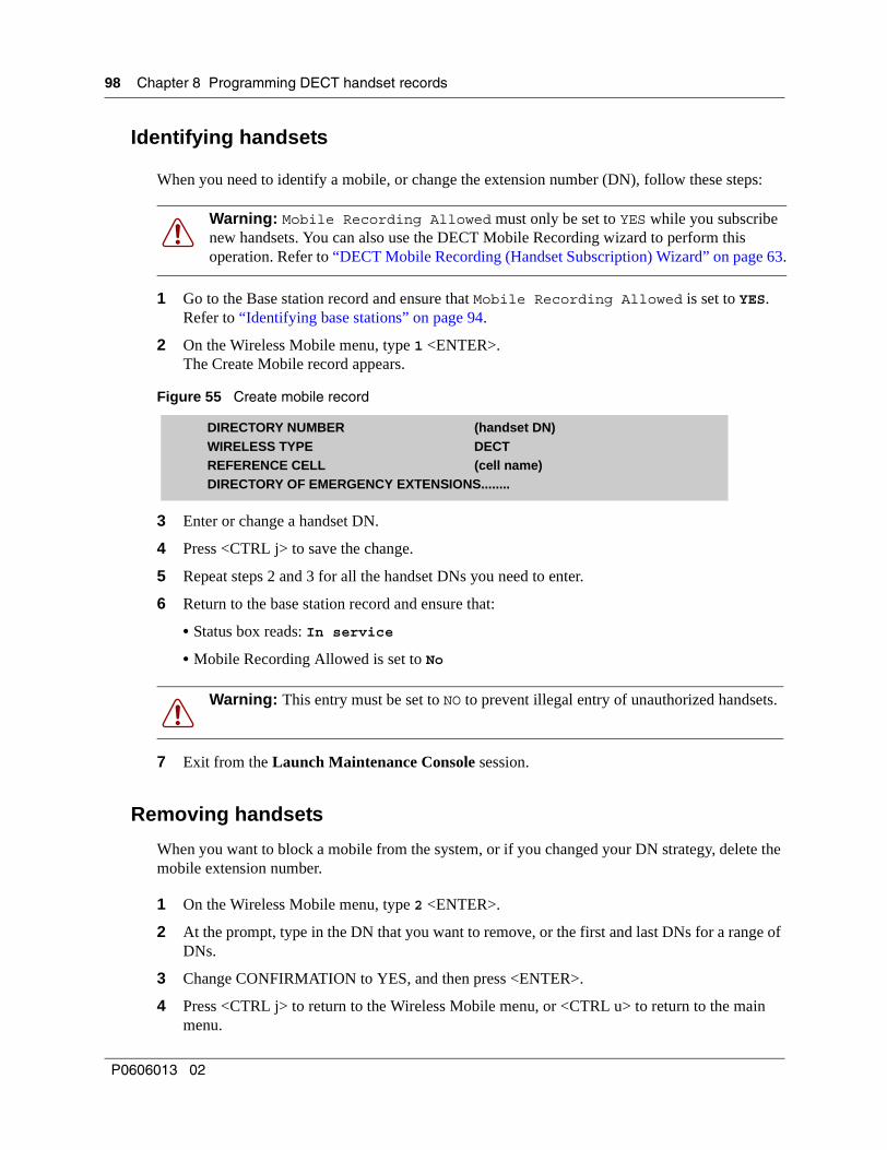
98 Chapter 8 Programming DECT handset records
Identifying handsets
When you need to identify a mobile, or change the extension number (DN), follow these steps:
1 Go to the Base station record and ensure that Mobile Recording Allowed is set to YES.Refer to “Identifying base stations” on page 94.
2 On the Wireless Mobile menu, type 1 <ENTER>.The Create Mobile record appears.
Figure 55 Create mobile record
3 Enter or change a handset DN.
4 Press <CTRL j> to save the change.
5 Repeat steps 2 and 3 for all the handset DNs you need to enter.
6 Return to the base station record and ensure that:
• Status box reads: In service
• Mobile Recording Allowed is set to No
7 Exit from the Launch Maintenance Console session.
Removing handsets
When you want to block a mobile from the system, or if you changed your DN strategy, delete the mobile extension number.
1 On the Wireless Mobile menu, type 2 <ENTER>.
2 At the prompt, type in the DN that you want to remove, or the first and last DNs for a range of DNs.
3 Change CONFIRMATION to YES, and then press <ENTER>.
4 Press <CTRL j> to return to the Wireless Mobile menu, or <CTRL u> to return to the main menu.
Warning: Mobile Recording Allowed must only be set to YES while you subscribe new handsets. You can also use the DECT Mobile Recording wizard to perform this operation. Refer to “DECT Mobile Recording (Handset Subscription) Wizard” on page 63.
Warning: This entry must be set to NO to prevent illegal entry of unauthorized handsets.
DIRECTORY NUMBER (handset DN)WIRELESS TYPE DECTREFERENCE CELL (cell name)DIRECTORY OF EMERGENCY EXTENSIONS........
P0606013 02

Chapter 8 Programming DECT handset records 99
Confirming the handset extension record
The mobiles must have a route from the DECT to the Business Communications Manager system. This should be a default to your system, but ensure that the settings described in this section are correct.
To do this procedure, you need to know the DNs for the handsets you install.
1 Navigate to the Telephony Management menu.
Figure 56 Telephony Management menu
2 Type 1 <ENTER>. The Extension Data menu appears.
Figure 57 Extension Data menu
3 Type 1 <ENTER>. The Extension Characteristics menu appears.
Figure 58 Extension Characteristics menu
1 EXTENSION DATA2 EXTERNAL TRUNK DATA3 NUMBERING PLAN4 OPERATOR MANAGEMENT5 CALL DISTRIBUTION MANAGEMENT6 CALENDAR MANAGEMENT7 PARAMETER MANAGEMENT8 WIRELESS MANAGEMENT
ENTER YOUR CHOICE ..
1 EXTENSION CHARACTERISTICS2 LOGICAL SUBSCRIBER MANAGEMENT3 AUTOMATIC DIRECTORY NUMBER ASSIGNMENT4 HUNT GROUP CHARACTERISTICS5 ADD/DELETE EXTENSIONS6 EXTENSION DIRECTORY7 CATEGORY MANAGEMENT8 PROGRAMMING EXTENSIONS9 OTHER EXTENSION DATAENTER YOUR CHOICE ..
BY EQUIPMENT NUMBER ........
BY DIRECTORY NUMBER ........
RECORD DELETED IF DIRECTORY CHANGED NO
DECT Installation and Maintenance Guide

100 Chapter 8 Programming DECT handset records
4 Tab down to the By Directory Number field.
5 Enter the DN for the cordless handset, and press <ENTER>.The Directory Number Selection record appears.
Figure 59 Handset record, page 1
6 Ensure the DID DN plan 1 field has the same directory number as the previous field. This is the DN number of the handset.Note: This step makes it unnecessary to assign the DNs to the Loop records in the Business Communications Manager.
7 Use <ESC m> to navigate to the second page.
Figure 60 Handset record, page 2
8 Ensure that Access To Route TONSTAR is set to YES.
DECT MOBILE EXTENSIONSUBSCR. STATUS IN SERVICEDIRECTORY NUMBER 16289
DID DN PLAN 1 16289EXTENSION NAME <USER NAME>REFERENCE CELLINTEGRATED VOICE BOX (IVB) NOSERVICE BEARER SPEECHDIRECTORY OF EMERGENCY EXTENSIONS ....DAY CATEGORY INTERNATIO.NIGHT CATEGORY INTERNATIODAY DISCRIMINATION RANGE .......NIGHT DISCRIMINATION RANGE .......
HOT LINE TYPE .....INTERCOM TYPE NO MONITORING
PAGING GROUP NUMBER 1 0..PAGING GROUP NUMBER 2 0..ACCESS TO ROUTE TONSTAR YESACCESS TO PAGING NCPRIVILEGED SET NCPICK UP PROTECTION OVERRIDE NCLOCKING ALLOWED YESUNLOCKING ALLOWED YESUSER MOBILE RECORDING YESPICK UP PROTECTION NONIGHT CATEGORY OVERRIDE YES
P0606013 02

Chapter 8 Programming DECT handset records 101
9 Use <ESC m> to navigate to the third page which shows the External forwarded allowed field.
Figure 61 Handset record, page 3
10 Ensure the External forwarding allowed is set to YES.
11 Exit to the Unified Manager.
CALL FORWARDING PROTECTION NODYNAMIC PROTECTION YESDO NOT DISTURB ALLOWED YESINTRUSION ALLOWED YESINTRUSION ACCEPTED YESPRE-EMPTIVE REROUTING TO VOICE MAIL NOUSE OF DISA FUNCTION NOCALL WAITING ACCEPT AND BEEPRETURN TO CONSOLE ON SPEC. TIME-OUTNOEXTERNAL FORWARDING ALLOWED YESASSISTANT FORWARDING ALLOWED YESSPEAKER PAGING YESID SENT TO PUBLIC NETWORK A.I.D.ID SENT TO PRIVATE NETWORK A.I.D.ID SENT CAN BE MODIF. FOR EACH CALL NO
DECT Installation and Maintenance Guide

102 Chapter 8 Programming DECT handset records
P0606013 02

103
Chapter 9Maintaining and upgrading DECT software
This chapter describes the backup and restore portion of the DECT Tools, which are located under the Unified Manager first-page Maintenance button or under the BRU menu within the Unified Manager application.
This section includes the following information:
• “Accessing the BRU screen, Unified Manager menu” on page 103
• “Accessing the BRU screen, DECT Tools menu” on page 104
• “Backup and Restore DECT module data” on page 105
Accessing the BRU screen, Unified Manager menu
1 Start the Unified Manager.
2 Do the following to check that the correct DECT module is selected:
a On the navigation tree, click the Resources key.
b Click on DECT.
c On the Maintenance Selection tab, confirm the module name, or select the correct module.
3 At the top of the navigation tree, click on BCM.
4 Under Tools, click on BRU.
5 At the prompt, enter the user name and password for the supervisor account.
Note: The supervisor account user name and password are the user name and password you used to access the Unified Manager. This password must have administrative privileges.
A new window appears.
6 Refer to each section for specific instructions about what to do next.
Note: You must use Microsoft Internet Explorer 5.5 or higher to use the BRU Utility.
DECT Installation and Maintenance Guide
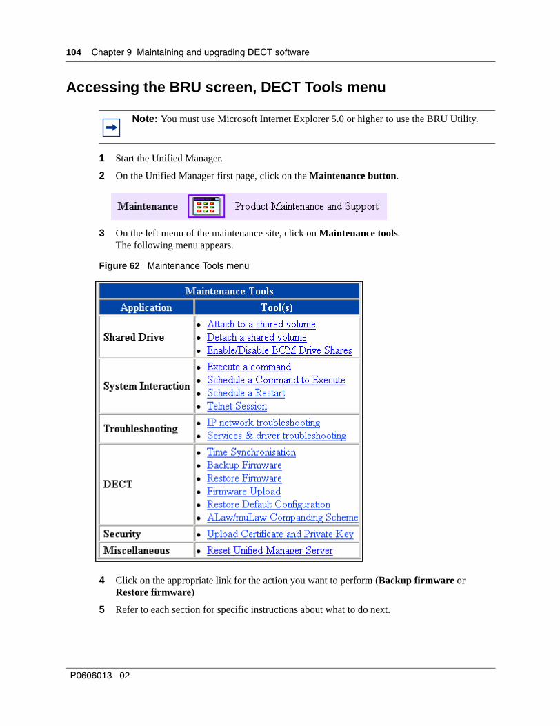
104 Chapter 9 Maintaining and upgrading DECT software
Accessing the BRU screen, DECT Tools menu
1 Start the Unified Manager.
2 On the Unified Manager first page, click on the Maintenance button.
3 On the left menu of the maintenance site, click on Maintenance tools.The following menu appears.
Figure 62 Maintenance Tools menu
4 Click on the appropriate link for the action you want to perform (Backup firmware or Restore firmware)
5 Refer to each section for specific instructions about what to do next.
Note: You must use Microsoft Internet Explorer 5.0 or higher to use the BRU Utility.
P0606013 02

Chapter 9 Maintaining and upgrading DECT software 105
Backup and Restore DECT module data
One of the special features of the DECT system is that part of the processing for the cordless handsets occurs separately through the DECT module software.
As such, this data must be backed up, particularly prior to updating the software or before any updates on the Business Communications Manager.
This section describes the DECT backup and restore procedures:
• “Backing up DECT data” on page 105
• “Restoring DECT data” on page 107
Backing up DECT data
The following procedure describes the backup process in detail.
1 Open the BRU screen. Refer to “Accessing the BRU screen, Unified Manager menu” on page 103 or “Accessing the BRU screen, DECT Tools menu” on page 104.
The backup screen appears.
Figure 63 Backup and Restore Utility screen
2 Under Backup Location, ensure the correct path is specified for your backup data. If not, click the Volume button, and change the path on the resulting screen.
3 Under Select BCM Component(s), select DECT OAM.
Warning: Perform this procedure during slow periods, as it requires system resources.
DECT Installation and Maintenance Guide

106 Chapter 9 Maintaining and upgrading DECT software
4 Under Backup Action, select the schedule information that you want.
• If you select the Perform the backup now button, leave the other fields blank and click on the START BACKUP button.
• If you select the Schedule the backup button, you need to also select the frequency and timing of the backup process. Then click on the SCHEDULE THE BACKUP button.
Figure 64 Scheduling a backup, one time
One-time only backup
Daily, or Weekly schedule (choose one or more days of the week)
Monthly schedule
P0606013 02

Chapter 9 Maintaining and upgrading DECT software 107
Restoring DECT data
This procedure disrupts service to DECT handsets since it replaces whatever DECT data is currently on the Business Communications Manager.
The following procedure describes how to restore data that you have archived.
1 Open the BRU screen. Refer to “Accessing the BRU screen, Unified Manager menu” on page 103 or “Accessing the BRU screen, DECT Tools menu” on page 104.
The backup screen appears.
Figure 65 Backup and Restore Utility screen
2 Click on the Restore tab to bring up the restore screen.
Figure 66 Backup and Restore Utility, restore screen
3 Under Backup Location, ensure the correct path is specified to your backup data. If not, click the Volume button, and change the path on the resulting screen.
DECT Installation and Maintenance Guide

108 Chapter 9 Maintaining and upgrading DECT software
4 Under Select BCM Component(s), select BCM Version Compare.
5 Under Restore Options, select the radio button to either restore the files only if they are different, or to restore the files, regardless of how they compare to the system version.
6 Click on the START RESTORE button.
Viewing the backup/restore schedule
If you have scheduled backups or restores for future dates, you can check the scheduling.
The following procedure describes how to restore data that you have archived.
1 Open the BRU screen. Refer to “Accessing the BRU screen, Unified Manager menu” on page 103 or “Accessing the BRU screen, DECT Tools menu” on page 104.
The backup screen appears.
Figure 67 Backup and Restore Utility screen
2 Click on the Schedule tab.
Figure 68 Backup and Restore Utility, schedule screen
P0606013 02

109
Chapter 10Troubleshooting and Alarm Monitoring
This section describes how to monitor alarms on the DECT module and what actions to take when they occur.
The information in this section includes the following:
• “Radio base station fault on startup” on page 109
• “Business Communications Manager application control” on page 109
• “Viewing and changing the DECT Alarm Monitor status” on page 112
• “Viewing alarms” on page 113
• “Base station/handset troubleshooting” on page 113
• “Changing the TCPPort” on page 114
• “Monitoring the DECT module LEDs” on page 114
• “Determining module companding law setting” on page 115
Refer to the Management User Guide for troubleshooting information about the Business Communications Manager.
Radio base station fault on startupConnect a PHONIS set or an ISDN tester as a replacement for the radio base station. As a rule, this configuration checks the two ISDN pairs for continuity.
Business Communications Manager application controlThe Diagnostics section of the Unified Manager contains Service Manager. This utility allows you to monitor the state of the DECT system and Maintenance console. It can also be used to start or stop the service.
1 Open the Diagnostics menu and click Service Manager. A list of services appears.
2 Scroll to find the DECT applications (DECTAlarms, DECTMtce, DECTOAM). The following figure shows the Services List.
Figure 69 Services list
DECT Installation and Maintenance Guide
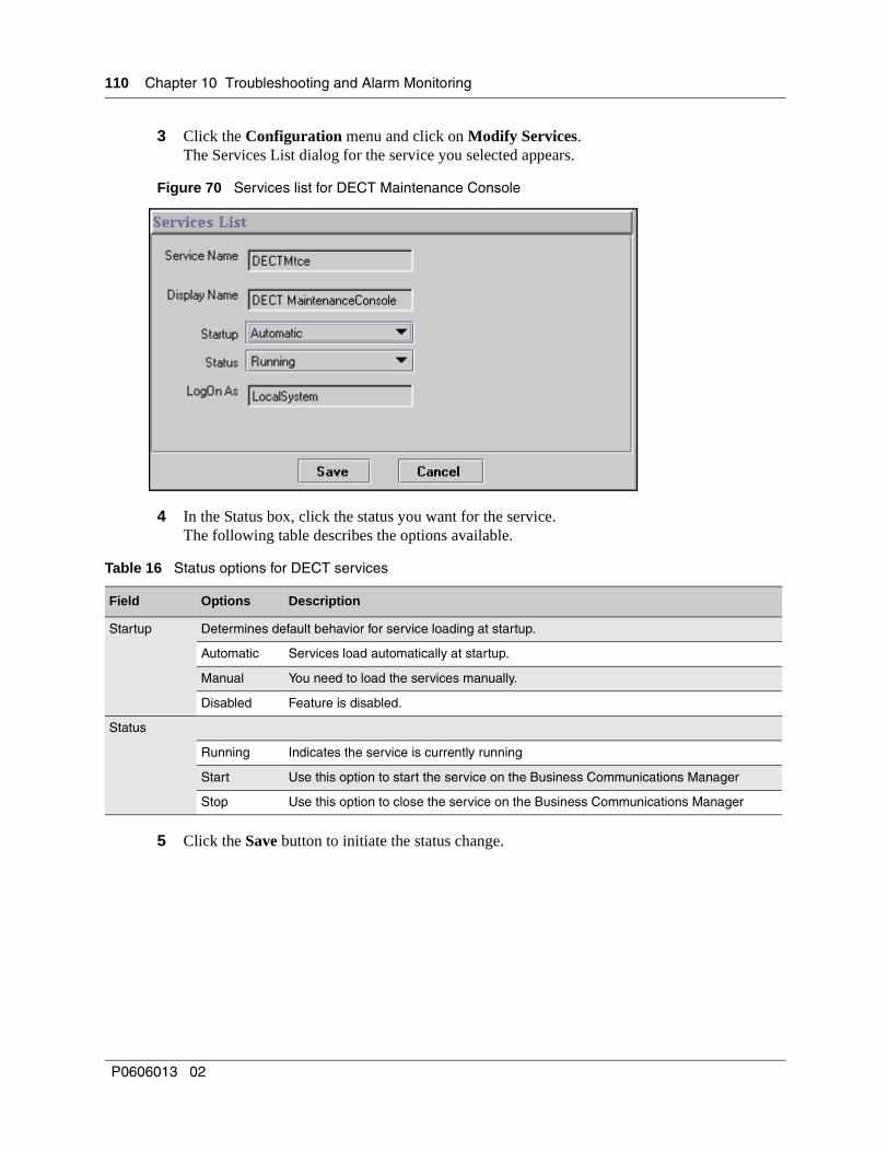
110 Chapter 10 Troubleshooting and Alarm Monitoring
3 Click the Configuration menu and click on Modify Services.The Services List dialog for the service you selected appears.
Figure 70 Services list for DECT Maintenance Console
4 In the Status box, click the status you want for the service. The following table describes the options available.
5 Click the Save button to initiate the status change.
Table 16 Status options for DECT services
Field Options Description
Startup Determines default behavior for service loading at startup.
Automatic Services load automatically at startup.
Manual You need to load the services manually.
Disabled Feature is disabled.
Status
Running Indicates the service is currently running
Start Use this option to start the service on the Business Communications Manager
Stop Use this option to close the service on the Business Communications Manager
P0606013 02
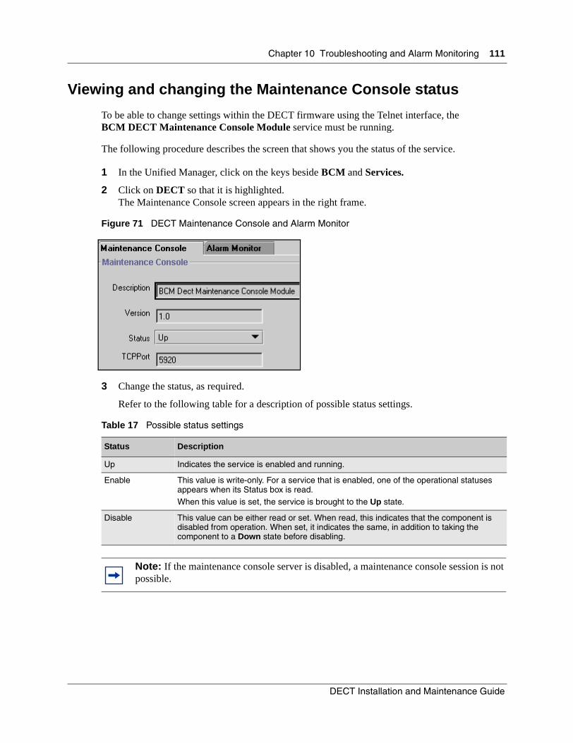
Chapter 10 Troubleshooting and Alarm Monitoring 111
Viewing and changing the Maintenance Console status
To be able to change settings within the DECT firmware using the Telnet interface, the BCM DECT Maintenance Console Module service must be running.
The following procedure describes the screen that shows you the status of the service.
1 In the Unified Manager, click on the keys beside BCM and Services.
2 Click on DECT so that it is highlighted.The Maintenance Console screen appears in the right frame.
Figure 71 DECT Maintenance Console and Alarm Monitor
3 Change the status, as required.
Refer to the following table for a description of possible status settings.
Table 17 Possible status settings
Status Description
Up Indicates the service is enabled and running.
Enable This value is write-only. For a service that is enabled, one of the operational statuses appears when its Status box is read.When this value is set, the service is brought to the Up state.
Disable This value can be either read or set. When read, this indicates that the component is disabled from operation. When set, it indicates the same, in addition to taking the component to a Down state before disabling.
Note: If the maintenance console server is disabled, a maintenance console session is not possible.
DECT Installation and Maintenance Guide

112 Chapter 10 Troubleshooting and Alarm Monitoring
Viewing and changing the DECT Alarm Monitor status
If you want the system to record DECT alarms, ensure that the DECT alarm monitor is enabled and running. The following procedure explains how to find the screen where you can view or change this information.
1 In the Unified Manager, click on the keys beside BCM and Services.
2 Click on DECT so that it is highlighted.The Maintenance Console screen appears in the right frame.
3 Click the Alarm Monitor tab. The Alarm Monitor screen appears.
Figure 72 DECT Maintenance Console and Alarm Monitor
4 Change the Status, as required. Refer to the following table for information about the status settings.
Table 18 Possible status settings
Status Description
Up Indicates the service is enabled and running.
Enable This value is write-only. For a service that is enabled, one of the operational statuses appears when its Status box is read.When this value is set, the service is brought to the Up state.
Disable This value can be either read or set. When read, this indicates that the component is disabled from operation. When set, it indicates the same, in addition to taking the component to a Down state before disabling.
Note: If the Alarm Monitor service is disabled, DECT alarms are not recorded in the Event Logger. These services must always remain enabled.
P0606013 02

Chapter 10 Troubleshooting and Alarm Monitoring 113
Viewing alarms
An enabled status for the Alarms Manager allows the alarms to write to a log on the Business Communications Manager. Access this information through the Unified Manager.
1 Open the Unified Manager.
2 Under BCM, highlight System.
3 Click the Fault menu, then click Alarm Banner.
An Alarm Banner appears, listing the number of alarms received under each priority, and the total number of alarms received.
Figure 73 Alarm Banner
4 Click the button for the fault list you want to view.The Alarm Browser window appears. This window lists all the alarms in that category.
5 Click the error you want to review.
6 Click Actions, and then click on Display Details.The Alarm Details screen appears outlining error details.
Base station/handset troubleshooting
The following table lists some possible problems and an explanation for the situation.
Table 19 Base station/handset troubleshooting
Problem Description
The base station cannot be loaded. The base station state changes to Faulty.
Disable it and try to load the base station as a two-channel base. When software loading succeeds, disable it again and put it in service as a 4-channel base.
When trying to subscribe a handset to the system, it continues to display Failed.
Possible causes:• The handset has not been created in the software.
• If the handset is subscribed to other bases, delete the bases and try again.
DECT Installation and Maintenance Guide

114 Chapter 10 Troubleshooting and Alarm Monitoring
Changing the TCPPortThe TCP port address must only be changed if some future feature requires this port.
To change the TCP port address:
1 In the Unified Manager, go to BCM, Services, DECT
2 Click Maintenance Console.
3 Enter the new TCPPort.
4 Set Status to Disable.
5 Wait until the system indicates the port is disabled.
6 Set Status back to Enable.
Monitoring the DECT module LEDs
The Power and Status LEDs on the module are both solid green when the module is operating properly. If an LED is off or blinking, use the table below to detect the cause.
Bad speech quality Check that the relevant base station is in service. If this is a temporary problem, then it is possible all the channels were busy and the handset was trying to access a more distant base station.If the problem does not correct itself, then cell coverage must be redesigned.
The handset name on the set is not the name that appears on called display sets.
Check the name on the DECT menu, as well as the name entered into the handset itself.
System performance presents problems such as with handovers, noise, one way speech in all areas.
Assuming that the site map and deployment requirements were followed exactly, take everything out of service and return it to service in sequence.
Table 20 LED states
Power(working status)
Status(hardware status) Details
Off Off No power applied to the module or failure of the module power converter.
On Off Field Programmable Gate Array (FPGA) not downloaded. This indicates that the MSC has not started correctly.
Table 19 Base station/handset troubleshooting (continued)
Problem Description
P0606013 02

Chapter 10 Troubleshooting and Alarm Monitoring 115
Determining module companding law setting
If you need to replace your DECT module, or if you replaced your Business Communications Manager base unit, you must ensure that the DECT module downloads the correct firmware for the companding law your region requires. The module defaults to a-law.
If you are unsure of which companding law your DECT module is set to, you can access the module interface and check.
1 From the main DECT interface menu, type 1 <ENTER>.The Telephony Management menu appears.
2 Type 7 <ENTER>.The Parameter Management menu appears.
3 Type 2 <ENTER>.The Miscellaneous Parameters menu list.
4 Press <Esc>e on your keyboard to scroll to the end of the list.
5 In Modification of other Parameters, type YES, then press <ENTER>.
6 In Parameter no. in decimal, type 372, then press <ENTER>.The resulting value will be either blank or 1.
blank = module is set to a-law1= module is set to µ-law.
WARNING: Do not change this setting!
7 If the module needs to be reset to a different companding law, refer to “Configuring the module for µ-law” on page 40 which explains how to perform the various steps that must be taken to download the correct firmware and to reset the module defaults.
On Blinking Operation problem:
• no DS256 link detected• DS256 frame alignment lost• Bandwidth not allocated
• Module is in maintenance stateNote: DS256 is the bus that connects the media bay modules to the MSC.
Blinking Blinking Hardware problem• partial failure of power converter• thermal overload
• fan failure
On On Module is ready to operate.
Table 20 LED states (continued)
Power(working status)
Status(hardware status) Details
DECT Installation and Maintenance Guide

116 Chapter 10 Troubleshooting and Alarm Monitoring
P0606013 02

117
Appendix AQuick reference to DECT module programming
If you have an existing DECT system that you do not want to run the DECT Configuration Wizard on, you can use the Maintenance Console in the Unified Manager to accomplish the configurations you require.
Familiarize yourself with opening the DECT interface. Refer to ”Accessing the Maintenance Console” on page 78. Details about setting up system lines and sets are provided in the Business Communications Manager Programming Operations Guide.
The chart on the following two pages provides the menu names and a brief description of the information required for each step of programming your DECT module, base stations, and handsets using the Maintenance Console.
Click on the following title to go to the DECT Programming Quick Reference Guide
DECT Installation and Maintenance Guide
118 Appendix A Quick reference to DECT module programming
P0606013 02
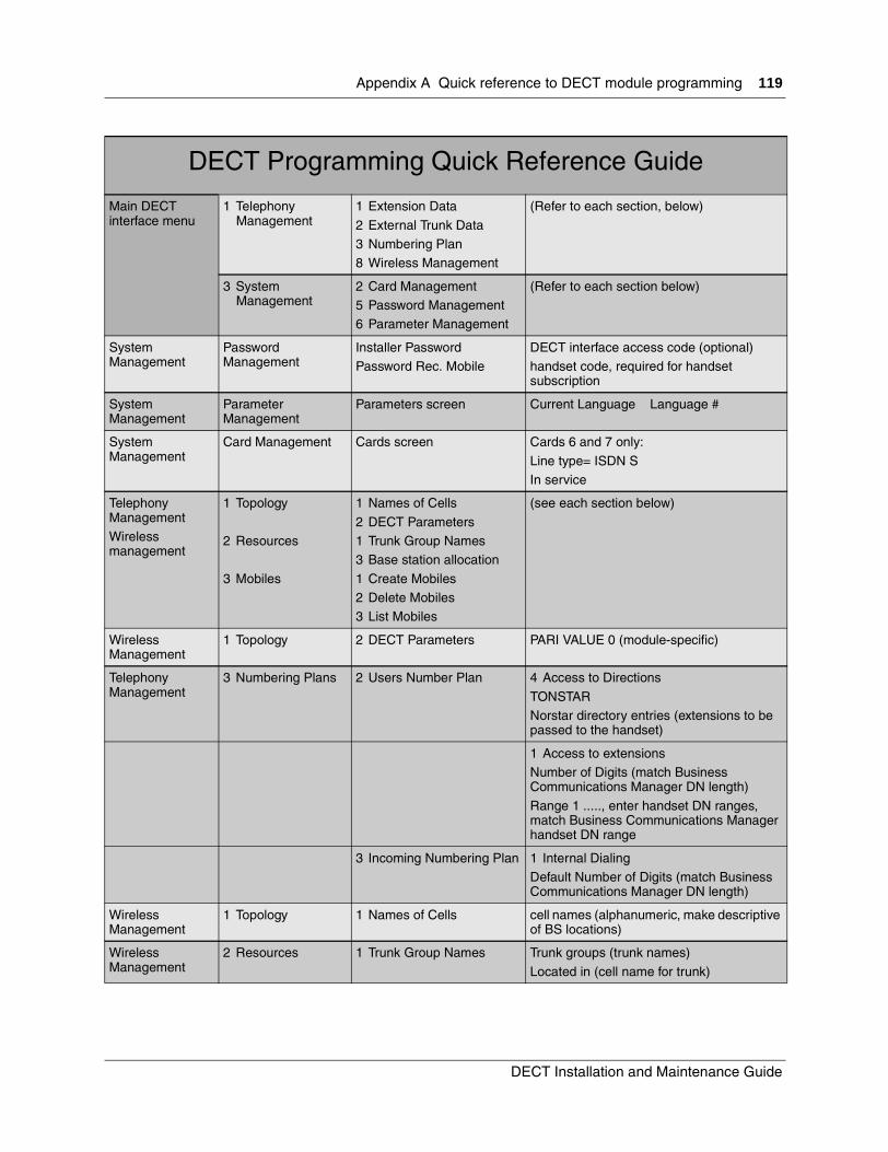
Appendix A Quick reference to DECT module programming 119
DECT Programming Quick Reference Guide
Main DECT interface menu
1 Telephony Management
1 Extension Data
2 External Trunk Data3 Numbering Plan8 Wireless Management
(Refer to each section, below)
3 System Management
2 Card Management5 Password Management6 Parameter Management
(Refer to each section below)
System Management
Password Management
Installer PasswordPassword Rec. Mobile
DECT interface access code (optional)handset code, required for handset subscription
System Management
Parameter Management
Parameters screen Current Language Language #
System Management
Card Management Cards screen Cards 6 and 7 only:
Line type= ISDN SIn service
Telephony ManagementWireless management
1 Topology
2 Resources
3 Mobiles
1 Names of Cells
2 DECT Parameters1 Trunk Group Names3 Base station allocation
1 Create Mobiles2 Delete Mobiles3 List Mobiles
(see each section below)
Wireless Management
1 Topology 2 DECT Parameters PARI VALUE 0 (module-specific)
Telephony Management
3 Numbering Plans 2 Users Number Plan 4 Access to Directions
TONSTARNorstar directory entries (extensions to be passed to the handset)
1 Access to extensionsNumber of Digits (match Business Communications Manager DN length)
Range 1 ....., enter handset DN ranges, match Business Communications Manager handset DN range
3 Incoming Numbering Plan 1 Internal DialingDefault Number of Digits (match Business Communications Manager DN length)
Wireless Management
1 Topology 1 Names of Cells cell names (alphanumeric, make descriptive of BS locations)
Wireless Management
2 Resources 1 Trunk Group Names Trunk groups (trunk names)
Located in (cell name for trunk)
DECT Installation and Maintenance Guide

120 Appendix A Quick reference to DECT module programming
3 Base Station allocation By equipment number: 6.0
Status: disabledMobile recording allowed: Yes (for one station only; set all other stations to No)
Trunk group: (from list)Rad. Base type: 4 CHANSynchronization: VIA BIT M FRAME
Enable base station.Go to next record
Wireless Management
3 Mobiles 3 List Mobiles Shows existing listed mobiles and current state
1 Create Mobiles Extension Number (handset DN)Wireless type DECT
Reference cell (cell name)
2 Delete Mobiles Enter DNs you want to remove.
Telephony Management
1 Extension data 1 Extension Characteristics By Directory Number (DN number of handset or leave blank to view all)Handset record
page 1: Directory Number and DID DN PLAN 1 have same number.page 2: Access to Route TONSTAR: Yes
page 3: External forwarding allowed: Yes
Business Communications Manager System, Unified Manager settings
Resources/Media Bay Module/
Bus ## Ensure module type is Trunk Module
Services, Telephony services, System DNS
Handset DNs Set up handsets
Default DNs:• New Business Communications Manager: 597-624• Upgraded 2.0 Business Communications Manager: 501-532
Services, Telephony services, System DNs
DN of twinned desk set
Enter handset DN in Answer DN
Unified Manager, various menus Set up lines, etc., as for other system setsRefer to the Programming Operations Guide.
Handset subscription
Declare Base Number
1
Enter Code (eight digits) Enter the set DN, then add enough digits of the mobile password to make up eight digits.
Test handsets on system
DECT Programming Quick Reference Guide
P0606013 02

121
Appendix BCordless handset verification
If the C4010 or C4020 handset does not subscribe or operate correctly, use the following section to determine if it is properly subscribed and correctly assigned to the DECT system.
Determining handset subscriptionIf the handset is already subscribed to the base station number you want to use, you need to unsubscribe the handset from that number.
This procedure describes how to find out if the handset was previously subscribed.
1 Turn on the handset.
2 Do one of the following:
• If this message appears, press the left arrow button on the handset to confirm OK, then subscribe the handset.
• If this message appears, press the left arrow button , then go to step 3.
3 Press the double-arrow key until Select Base appears.
4 Press the left arrow button , under Select Base.The system displays the radio base station numbers already in use.
5 If the number you want to use has already been subscribed, refer to “Unsubscribing the handset” on page 122.
Note: If the handset does not follow these procedures, check the user manual that came with the set for specific troubleshooting information.
Declare mobile set to rbs nbr?
12345678 OK
Mobile set out of range
bis Menu
DECT Installation and Maintenance Guide
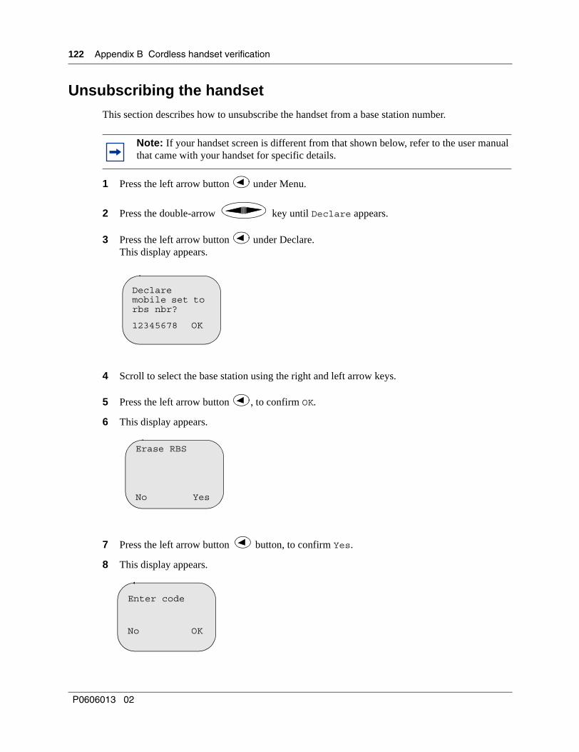
122 Appendix B Cordless handset verification
Unsubscribing the handsetThis section describes how to unsubscribe the handset from a base station number.
1 Press the left arrow button under Menu.
2 Press the double-arrow key until Declare appears.
3 Press the left arrow button under Declare.This display appears.
4 Scroll to select the base station using the right and left arrow keys.
5 Press the left arrow button , to confirm OK.
6 This display appears.
7 Press the left arrow button button, to confirm Yes.
8 This display appears.
Note: If your handset screen is different from that shown below, refer to the user manual that came with your handset for specific details.
Declare mobile set to rbs nbr?
12345678 OK
Erase RBS
No Yes
Enter code
No OK
P0606013 02
Appendix B Cordless handset verification 123
9 Press the Clear (C) button.
The mobile is unsubscribed and the screen returns to the main menu.
10 Subscribe the handset to the DECT system. Refer to “Subscribing DECT cordless handsets” on page 65.
Testing the handsetTest subscribed handsets by walking around the transmission area and confirming that the handset works. This test also confirms that the base stations can transfer the signal, as required.
Use the following procedure to perform more detailed tests, as required.
There are two ways of testing the handset: while in use and while in the idle mode.
1 Testing the handset while in use:
a Press the left arrow button to select Menu
b Press keys 1, 5 and 9 simultaneously.
c Exit this menu by holding down the Clear button.
2 Testing an idle handset:
a Ensure the set is in the idle mode.
b Press the left arrow button to select Menu.
c Press 7.
d Press 6.
e Press the right arrow button and hold it down until the test mode display appears.
f Exit this menu by holding down the Clear button.
Warning: This testing must be carried out only by authorized personnel. Entering incorrect commands can cause the handset to malfunction.
C
C
C
DECT Installation and Maintenance Guide
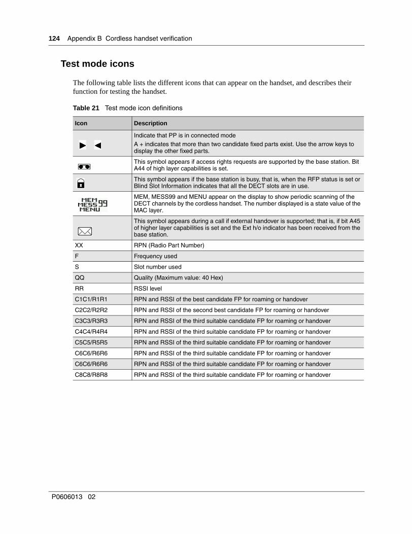
124 Appendix B Cordless handset verification
Test mode icons
The following table lists the different icons that can appear on the handset, and describes their function for testing the handset.
Table 21 Test mode icon definitions
Icon Description
Indicate that PP is in connected modeA + indicates that more than two candidate fixed parts exist. Use the arrow keys to display the other fixed parts.
This symbol appears if access rights requests are supported by the base station. Bit A44 of high layer capabilities is set.
This symbol appears if the base station is busy, that is, when the RFP status is set or Blind Slot Information indicates that all the DECT slots are in use.
MEM, MESS99 and MENU appear on the display to show periodic scanning of the DECT channels by the cordless handset. The number displayed is a state value of the MAC layer.
This symbol appears during a call if external handover is supported; that is, if bit A45 of higher layer capabilities is set and the Ext h/o indicator has been received from the base station.
XX RPN (Radio Part Number)
F Frequency used
S Slot number used
QQ Quality (Maximum value: 40 Hex)
RR RSSI level
C1C1/R1R1 RPN and RSSI of the best candidate FP for roaming or handover
C2C2/R2R2 RPN and RSSI of the second best candidate FP for roaming or handover
C3C3/R3R3 RPN and RSSI of the third suitable candidate FP for roaming or handover
C4C4/R4R4 RPN and RSSI of the third suitable candidate FP for roaming or handover
C5C5/R5R5 RPN and RSSI of the third suitable candidate FP for roaming or handover
C6C6/R6R6 RPN and RSSI of the third suitable candidate FP for roaming or handover
C6C6/R6R6 RPN and RSSI of the third suitable candidate FP for roaming or handover
C8C8/R8R8 RPN and RSSI of the third suitable candidate FP for roaming or handover
P0606013 02

125
Glossary
Antenna diversity
The base station has two internal antennas, which allows it to choose the strongest signal to send and receive.
Authentication key
This is part of the authentication procedure for the portable. When a call starts, the fixed part transmits a challenge to the portable part. The portable part calculates the proper response and sends it. After every call setup, the fixed and portable parts calculate a new authentication key for the next call.
Business Communications Manager
A PBX-like machine attached to the radio base stations that handles call processing, voice messaging, data routing and telephony.
Cell
For the media bay module, the term cell includes a series of radio base stations representing the basic roaming entity for cordless handsets. The media bay module actually knows the cell hosting this cordless handset but does not know the radio area, which is the radio base station to which this set is attached. A message sent to a cordless handset by the media bay module is sent to all radio base stations under this cell. Consequently, a cell typically represents a homogeneous space. One cell contains a maximum of eight base stations.
DSAA
DECT Standard Authentication Algorithm. Used to create the User Authentication Key.
EIC
Equipment Installation Code. This is a distributor reference, for example, Matra Nortel Communications, managed by ETSI.
4-channel station
Refers to a radio base station that can handle four calls simultaneously.
FPN + FPS
Fixed Part Number and Fixed Part Sub-number. This is a network user reference managed by Matra Nortel Communications.
Erlang
One Erlang is an average traffic load caused by one basic DECT speech connection, using one frequency/timeslot pair, all the time.
Handover
A cordless handset can abandon one radio connection for another, either to the same radio base station or to another one.
DECT Installation and Maintenance Guide

126 Glossary
Map
A chart prepared after the site survey, showing the positions of the radio base stations, the areas they cover, and the cells into which they are grouped.
Media bay module
This is a modularized box containing the hard connections to various peripheral telephony equipment. Media bay modules are installed in bays on the Business Communications Manager or a Business Communications Manager extension unit.
Mobile
The DECT cordless handset.
Overlapping Base Stations
Each base station has the same radio coverage, for example aisle, floor, but manages different groups of cordless handsets.
PARK
Portable Access Right Key (determines the right for this DECT cordless handset)
Password
A secret PIN code used by the fixed and portable parts to establish the right of the portable to use the system.
Radio area
Radio area refers to the space in which this radio base station radiates. If detected by traffic conditions (number of simultaneous calls in this office), several radio base stations can be installed side by side and define almost the same Radio Area. In this case, these radio base stations are referred to as Overlapping Base Stations. The size of each Radio Area varies according to the topology.
Radio area centre
Location of the radio base station or antenna connecting up this radio area.
Radio base station
A radio base station incorporates two identical omni-directional transceivers. A coverage area for a radio base station is in free space, spherical in shape and centred at the radio base station. A radio base station must belong to a trunk.
Radio range
Distance between the radio area center and its boundary limit. A radio range is environment dependent.
Rand f
Random f number, a sequence of up to 10 digits used to calculate the User Authentication Key.
P0606013 02

Glossary 127
RJ45
The jack used on the radio base stations and the media bay module.
RNIS-S0 terminals
Réseau Numerique (à) Integration (de) Services (French for ISDN).
Site survey
This is the process of surveying the area where you want to locate the base stations and mapping out the best area to mount the components for best reception.
Traffic level
The number of telephone calls being made in a particular area.
Trunk
A communication line that connects the PBX to the central office. A trunk must be associated with a cell. A DECT trunk and a PBX MC 6500 trunk are two different concepts.
DECT Installation and Maintenance Guide

128 Glossary
P0606013 02
129
Index
Aaccess to directions 119
access to extensions 119
acronyms 14
add mobile 120
a-lawsetting module to mu-law 40
answer DN 120
antenna losses 24
antennasattaching external connections 59base station 58bi-directional 59BNC connector 60cables 24diagram 24extension cord 24external 23internal 23omni-directional 25
antistatic grounding strap 54
attenuation 55
Bback panel 54
backup 105
backup, see also BRU
base stationantennas 58area covered 22back panel 54cable length 21co-located stations 53connect external antennas 59connecting 57declaring base station 66default 66definition screen 70, 95descriptiondetailed description 22disable 28environmental specifications 26equipment numbers 70erase 122extension bracket 53firmware check 57
first station distance 21grounding 54identifying 94install on a wall 54installation considerations 53interface settings 95interference 55internal antennas 22LED status 58Mobile Recording wizard 63mounting kit 53outdoors 53overlapping 26power
supply, base station 26range 25removing the cover 54reset, DECT interface 67RJ45 connector 22see also radio base stationssignal processing 26simultaneous calls 25specifications 25switches 23telephony management 86testing
system 71troubleshooting communication 71unsubscribing the handset 122wireless management 91
base station allocation 119
base station busy indicator 124
base stationsquick reference to base stations 117
bi-directional antennas 59
BNC connector 60
BRI, DECT 2
BRIP LED 35
BRIS LED 35
BRU 105, 107, 108
BRU, see also backup, restore, and upgrade
bus, see DS30 channel
Business Communications Managerchecking the region 30install media bay module 31restart system 35setup requirement for DECT 21supported DECTs 18
DECT Installation and Maintenance Guide

130 Index
system shutdown 34
busy tone 74
CC4010 61
C4020 61
C8card management 81
CA1, base station switch 23
cablesantennas 24, 60base station 21base station cable lengths 57base station connections 55measurements for base station 55minimizing interference 55reconnecting 35screened pair 55transmit/receive 22
call capture 72
call forward 72
call numbering, incoming call 89
call shuttle 72
Call waitingWizard patch 48
caller ID, handset display 72
CallPilot voice mail 72
cancel call forward 72
card management 81, 119
card port number 94
celllogical trunk groups 92roaming area 75
cell names 91, 119
changing languages 80
channel scanning indicator 124
checking the region 30
climatic conditions 26
coaxial cable, antennas 23
cold start 30
commands, DECT interface 28
companding lawssetting module to mu-law 40
components, base station description
conference calls 71
configuration, accessing the wizards 49
connected mode indicator 124
connectors, RJ45 22
conventions, text 14
core firmware 28
create mobile 119, 120
crosstalk 55
Ctrl J 28
Ctrl U 28
Ddata links 28
declare base number, handset 120
declare base station 66, 122
DECTaccessing the wizards 49base station firmware check 57base station settings 95caller ID, handset 72card management 81cell names 91changing the TCP Port 114checking the region 30checking the region setting 30choosing DS30 channels 32configuration process 38connecting base stations 26connections to media bay module 26declare base station 66define radio base station 70electromagnetic compatibility 3equipment number, RJ45 jacksexternal antennas 59first base station 21handling second call on handset 72handset features 20handset roaming 74handset specifications 27handset subscription 61identify base station 94install media bay module 31interface commands 28interface description 2interference 55main interface menu 78module installation process 31module LED states 114number of handsetsoutside base stations 53PARI value 85password 66
P0606013 02

Index 131
programming overview 28query voice mail 72quick reference to programming 117restart system 35roaming area 75set password 79setting DIP switches 32setup process overview 21standards and specifications 2subscribing the handset 65switch settings for replacement module 33system management 79system shutdown 34telephony management 86testing setup 71third call in 72transfer and conference calls 71Unified Manager resources 39using lines 71wireless management 91
DECT Configuration wizard 47
DECT Mobile Recording wizard 63
DECT modulebackup, restore and upgrade 105connecting to base station 57description 18restoring backed up data 107schedule for backup/restore 108setting module to mu-law 40
DECT parameters 85, 119
DECT wizards 47
defaultbase station 66DNs 120password 28settings, wizard 47
define radio base station 67, 70
delete mobiles 119, 120
deploymentplanning requirements 22setup process 21
dialed number width 29
DIP switchesnew module 32replacing module 33
direct inward roaming 75
disable base stations 28
disconnect power 34
DND on busy 72
DNs
Configuration wizard 47DECT 33handset code 66incoming number plan 89setting up voice mail 73
download firmware 57
DS30 channel, determining 32
Eelectromagnetic compatibility 3
emulation screen 78
enable call waitingWizard patch 48
enter code, handset 120
environmentbase station specifications 26standards and specifications 2
equipment number 119
equipment numbersmodule jacks 70see RJ45 connectors
erase subscription 122
ETSI specifications 2
exchange protocol 75
expansion cabinet, disconnect power 34
extension bracket 53
extension characteristics 120
extension cordantennas 24generated losses 24maximum length 24
external antennasacceptable models 23base station 22connecting to base station 59outdoor base station 53
external handover indicator 124
external trunk data 119
external trunks 86
Ffaceplate, see front bezel
fast blink, LED 58
field programmable gate array (FPGA) 115
firmwareat startup 57call waiting wizard patch 48
DECT Installation and Maintenance Guide

132 Index
requires E1 28
FP roaming/handover indicator 124
frequency band 25
frequency of use indicator 124
front bezel 34
Ggain, antennas 24
generated losses, antenna extension cord 24
go to main menu 28
green LED 35, 58
grounding, inside the base station 54
Hhandset
C4010 and C4020 61caller ID 72component description 18Configuration wizard 47declare base number 120detailed description 27determining current subscriptions 121display buttons 65erase subscriptions 122features 20handling second call 72idle 74idle mode testing 123message waiting indicator 72password 119query voice mail 72quick reference to programming 117registration 61registration key 80roaming 74set password 79set to recording mode 28setup test 71standards and specifications 2subscribing 21, 61, 65subscription code 66subscription process map 61system features 19, 71telephony management 86test 21, 123third call 72unsubscribing 122wireless management 91
handsetscall waiting Wizard patch 48
hardwarebase station considerations 53LEDs indicate problem 115
Iidentifying the module 39
idle mode 123
impedance tests 57
incoming numbering plan 89, 119
independent set 71
installer password 80, 119
interfacebase station screen 95card management 81cell names 91commands 28define radio base station 70identify base station 94main menu 78numbering plan 86PARI value 85system management 79telephony management 86wireless management 91
interference, base station 55
internal antennasbase station 22removing plate 59
internal dialing 119
IP, changing the TCP Port 114
ISDNcompanding laws 40
LLAL value 75
language management 80
launch maintenance console 78
leak-tight cabinets 53
LEDbase station 58media bay modules 114monitor 35power 114states 114testing setup 71
list mobiles 119
located in cell 92
located status 74
P0606013 02

Index 133
loop resistance 55
losses at frequency 24
MMA821X12 81
mailbox 72
make calls 71
maximum length, antenna extension cord 24
media bay modulecomponent description 18connecting base stations 26installing 31
Meridian voice mail 72
message waiting 72
message waiting indicator 72
mobile password 119
mobile recording allowed 70, 95
mobile sets, see handsets 61
mobiles 119
moduleDIP switch settings 32DS30 channels 32interface commands 28LED states 114LEDs 35numbering plan 86PARI value 85quick reference to programming 117replacing, switch settings 33restart system 35system shutdown 34testing setup 71
module bay 34
mounting kit 53
move up a level 28
MSC, LED indicates trouble 115
mu-law, setting module 40
MWI, see message waiting indicator 72
Nname, caller ID 72
names of cells 119
non-located status 74
NOSTAR settings 119
number plan syntax 29
numbering plan 86, 119
incoming 89
numbering plans 119
Oopen emulation tool 78
operating temperature 25
operations, LEDs 115
out of range 121
outgoing calls, roaming 75
Ppaint warning 26
parameter management 119
PARI value 27, 85, 119
passwordhandset 79handset code 66quick reference guide 119record, mobile 80setting 79system default 28
PBX, C8 2
powerbase station 22disconnect server 34LED 35, 114
power supply 26
prime set 74
processhandset subscription 61install DECT module 31setting up DECT 21
programmingautomatic 57quick reference 117
publications, related 15
Qquality indicator 124
Rradio base station, see base station
radio base type 95
radio channels 25
radio part number indicator 124
receive calls 71
DECT Installation and Maintenance Guide

134 Index
recording mode 28
region, checking 30
registration key 80
relative humidity 26
removecover 54internal antenna plate 59mobile 120
requirements, deployment 22
reset base station 67
reset, warm reset 26
resources 119
resources, Unified Manager 39
restart system 35
restore 107
restore data 105
RFPI 74
rights requests support indicator 124
RJ45 connector 22, 55, 57, 70
roamingdirect inward 75outgoing calls 75overview 74restrictions 74
roaming area 75
RPN indicator 124
RSSI level indicator 124
SS202, base station switch 23
SARI 74
scanning channels indicator 124
schedule 108
screen pair cables 55
second call 72
see also cordless handset
setup process 21
shutdown system 34
signal processing 26
signalling channel throughout 25
simultaneous calls 25
site map 21
site surveydeployment guide 22handsets 27
slot number indicator 124
slow blink, LED 58
specificationshandset 27radio base station 25system standards 2
statusIn service 70, 95LED 35, 114
storage temperature 26
subscribe handsets 21
subscribingdetermining current connections 121erase 122Mobile Recording wizard 63unsubscribing 122
switchesCA1 and S202 23DIP switch settings 32
symbols 13
synchronization 95
system features, handset 19, 71
system management 79, 119
system restore 35
system shutdown 34
system startup, accessing the wizards 49
systems information 28
TTCP Port, changing 114
telephony management 86, 119
temperature tolerance range 26
testinghandsets 123idle mode 123system 71
text conventions 14
third call in 72
throughput channel 25
topology 119
transfer calls 71
transmission power 25
troubleshooting base station communication 71
trunk group 95, 119
trunk group names 92, 119
twinning handset with fixed set 71
P0606013 02

Index 135
twinning sets 120
Uuse frequency indicator 124
users number plan 119
Vvoice mail 72
voice mail, query system 72
VT100 emulation 78
Wwall, installing base station 54
wireless management 91, 119
Wizardenable call waiting patch 48
wizardsaccessing 49Configuration wizard 47DECT 47
DECT Installation and Maintenance Guide

136 Index
P0606013 02


