14

Buxton and Hollis, Maine Bar Mills and Canal Bridges
WINs: 19280.00 and 19281.00 December 2014
SPECIAL PROVISION SECTION 501- FOUNDATION PILES
MICROPILES Amend Standard Specification Section 501 – Foundation Piles to include the following: 501.01 Description. This work shall consist of furnishing, constructing and load testing a micropile foundation as shown in the Plans and as specified herein. The micropile Contractor is responsible for furnishing all materials, products, accessories, tools, equipment, services, transportation, labor and supervision required for installation and load testing of micropiles as shown on the Plans, per approved submittals and as specified herein. The micropile Contractor is advised that existing canal and auxiliary spillway retaining walls, which are considered vibration sensitive structures, are located in close proximity to the Work. Vibration monitoring and movement monitoring will be completed during installation of micropiles by the Department as specified in Special Provision 501 - Vibration and Movement Monitoring and Control. In addition, threshold and limiting vibration and horizontal and vertical deformation values are included in Special Provision 501 – Vibration and Movement Monitoring and Control. The micropile Contractor shall consider these limitations in preparing their bid. 501.011 Definitions. Definitions that apply within this Special Provision are: Bond Breaker - A device, sleeve or special treatment placed over the steel reinforcement that will prevent load transfer to the soil over that length. A bond breaker also provides full lateral support of the micropile over the length of the bond breaker. Grout placed in contact with the soil using gravity pressure only will not be considered to constitute a bond breaker. Bond Zone - The gravity grouted, pressure grouted, and/or post grouted length of a micropile that is bonded to the bedrock and transfers the applied loads to the surrounding bedrock. Factored Design Load (FDL) - The maximum factored compressive axial design load for a micropile as indicated on the Plans. Drill Casing - Steel pipe of flush joint type used in the drilling process to stabilize the drill hole. Extended Length - An additional micropile length resulting from a requirement that the micropile capacity be achieved below a given elevation. Typically, extended lengths are prompted by a conflict with subsurface elements (e.g., underground structure, utilities, etc.) or unreliable soil strata. Bond breakers may be required. Micropile - A small diameter, bonded, cast-in-place friction pile formed by removing material using non-vibratory and non-displacement methods to create a cased open, cylindrical hole in the ground, which is subsequently filled with grout and steel reinforcement. Mill Secondary - Mill rejected American Petroleum Institute (API) casing, a.k.a. “Mill Rejects,” “Structural Grade,” “Limited Service,” or “Minimum Test Pipe”.
1 of 13
Buxton and Hollis, Maine Bar Mills and Canal Bridges
WINs: 19280.00 and 19281.00 December 2014
Non-production pile - Non-production piles are micropiles that are not incorporated into the substructure. Permanent Casing - A steel casing installed in the upper portion of a micropile to increase the micropile's moment capacity and lateral capacity against horizontal loads. Positive circulation or flush - A method of progressing and cleaning out a hole for a micropile wherein drilling fluid is injected into the hole and returns upward along the outside of the drill casing. Production micropile - A micropile which will be incorporated into the structure's foundation. Recirculation - A method of handling drilling fluid where the fluid coming back out of the hole is captured in a pan and reused. Reverse circulation - A method of cleaning the inside of the drill casing. Drilling fluid is circulated down through the drill rods and returns upwards through the inside of the drill casing to flush the drill casing clean. Tremie grouting - A method used to place grout in a wet hole. A grout tube is placed to the bottom of the drill hole. While keeping the grout tube opening submerged in the grout, grout is pumped into the hole, causing the drilling fluid to be displaced upward. 501.012 Micropile Contractor’s Experience Requirements and Submittal. Four (4) weeks prior to the start of installation of the micropiles the micropile Contractor performing the work described in this Special Provision shall submit proof of successfully constructed micropiles using non-displacement methods immediately adjacent to vibration sensitive structures at two (2) projects under similar site conditions to those indicated in the Contract documents. Two (2) weeks prior to the start of installation of the micropiles, the micropile Contractor shall submit a list identifying the on-site supervisors, drill rig operators and load testers assigned to the project. On-site supervisors shall have supervised the successful installation of micropiles on at least two (2) projects under similar site conditions to those indicated in the contract documents. Drill rig operators and load testers shall have at least one (1) year experience in construction and load testing of micropile foundations, respectively. The Resident shall approve or reject the micropile Contractor's qualifications and staff within fourteen (14) working days after receipt of the submission. 501.013 Submittals. The micropile Contractor will not be allowed to begin work until all related submittal requirements are satisfied and found acceptable to the Resident and until baseline vibration and vertical and horizontal deformation measurements are taken by the Department along the existing canal and auxiliary spillway retaining walls. At least four (4) weeks prior to the start of installation of the micropiles the micropile Contractor shall prepare and submit the information outlined below. All submittals will be reviewed in accordance with Standard Specification Section 105.7, Working Drawings.
2 of 13

Buxton and Hollis, Maine Bar Mills and Canal Bridges
WINs: 19280.00 and 19281.00 December 2014
Include in the Micropile Installation Plan submittal: 1. List and description of proposed equipment to be used for micropile installation,
including drilling equipment, cleaning method, checking cleanliness of drill holes, centralizers, installing micropiles, tremie grouting, tensioning, load testing and load transfer.
2. Details of proposed procedures and sequence for micropile installation, including method of drilling, installation, and grouting.
3. Procedures for advancing through boulders and other obstructions. 4. Procedures for containment of drilling fluid and spoils, and disposal of spoils. 5. Procedures for preventing loss of ground and densification of in-situ soils, which
could result in damage to the existing canal and auxiliary spillway retaining walls. 6. Procedures for limiting vibrations and horizontal and vertical deformations of the
existing canal and auxiliary spillway retaining walls should the threshold and limiting values specified in Special Provision 501 – Vibration and Movement Monitoring and Control be approached or exceeded.
7. Procedures for removal of high-density corrugated polyethylene tubing and factory grout in advance and in preparation of anchor plate and nut placement.
8. Shop drawings for all structural steel, including the micropile components, corrosion protection system, micropile top attachment and bond length details. Provide information on the length of the casing sections to be used, as dictated by the length of the drill mast and by the available overhead clearance, and the resulting location of joints. Shop drawings shall include a plan showing micropile designations and verification and proof test micropile locations.
9. Quality Control Plan (QCP) for the grout, in accordance with Standard Specification Section 502.1701, Quality Control, Method A and B, with the following exception: There are no permeability or entrained air requirements. This plan shall also include a description of the procedures and equipment for placing the grout and the method for monitoring quality control of the mix. At a minimum, quality control shall include: Use of a Baroid Mud Balance per American Petroleum Institute (API) Recommended Practice (RP) 13B-1, Standard Procedure for Testing Water Based Drilling Fluids, to check the specific gravity of the mixed grout prior to placement of the grout into each micropile; and compressive strength testing in accordance with AASHTO T106/ASTM C109 at a frequency of no less than one set of three (3) 2-inch grout cubes each day of operation, or per every ten (10) micropiles, whichever occurs more frequently.
10. If proposed, details of post-grouting equipment and procedures, including the method, sequence of operations and equipment required.
11. Layout drawings showing the proposed sequence of micropile installation. 12. Detailed procedures for load testing, including shop drawings/procedures detailing the
monitoring system for measuring movements during verification and proof load tests. These procedures/shop drawings shall bear the seal of a Professional Engineer licensed in the State of Maine. Submit calibration reports for each test jack, pressure gauge, master pressure gauge and load cell to be used. The calibration tests shall have been performed by an independent testing laboratory and tests shall have been performed within sixty (60) days of the date submitted. The Resident shall approve or reject the calibration data within five (5) working days after receipt of the data. Testing shall not commence
3 of 13
Buxton and Hollis, Maine Bar Mills and Canal Bridges
WINs: 19280.00 and 19281.00 December 2014
until the Resident has approved the jack, pressure gauge and master pressure gauge calibrations.
Micropile installation records shall be submitted to the Resident within 24 hours after each micropile installation is completed. At a minimum the records shall include: micropile drilling, duration and observations; description of soil and bedrock encountered; rate of advancement; micropile inclination; approximate final tip elevation; cut-off elevation; nominal resistance; description of unusual behavior and/or conditions; deviations from planned parameters; grout volumes pumped; micropile materials and dimensions; micropile location; inspector name; drill method; drill rig operator. The micropile Contractor shall submit to the Resident within thirty (30) calendar days after completion of the micropile work a report containing:
1. As-built drawings showing the locations of the micropiles and the micropile lengths. 2. Detailed drilling records including depth to bedrock quality. 3. Micropile load test results and graphs.
501.02 Materials. For all steel remaining as a permanent part of the work, all Buy America provisions shall apply. All applicable subsections of Standard Specification Section 502, Structural Concrete, shall apply to the grout, including, but not limited to, Section 502.03, Materials, 502.04, Shipping and Handling, 502.05, Composition and Proportioning, 502.06, Batching and 502.07, Mixing and Delivery. Material certifications for the micropile components shall be provided. Admixture for Grout - Admixtures shall conform to the requirements of ASTM C494 or AASHTO M194. Expansive admixtures shall only be added to the grout used for filling sealed encapsulations. Admixture shall be compatible with the grout and mixed in accordance with the manufacturer’s recommendations. Their use will only be permitted after field tests on fluid and set grout properties. Admixtures containing chlorides are not permitted. Accelerators are not permitted. Admixtures that control bleed, improve flowability, reduce water content and retard set may be used in the grout, subject to the review and acceptance of the Resident. Bar Tendon Hex Nuts and Couplers - Bar Tendon Hex Nuts and Couplers shall conform to ASTM A108 and develop the ultimate tensile strength of the bars without evidence of any failure. Cement - All cement shall be Portland cement conforming to ASTM C150/AASHTO M85, Type II and shall be the product of one manufacturer. If the brand or type of cement is changed during the project, additional grout mix tests shall be conducted to ensure consistency of quality and performance. Centralizers and Spacers - Centralizers and spacers shall be fabricated from schedule 40 PVC pipe or tube, steel, or material non-detrimental to the reinforcing steel. Wood shall not be used. Centralizers and spacers shall be securely attached to the reinforcement; sized to position the reinforcement within 3/8 inch of plan location form center of micropile; sized to allow grout
4 of 13
Buxton and Hollis, Maine Bar Mills and Canal Bridges
WINs: 19280.00 and 19281.00 December 2014
tremie pipe insertion to the bottom of the drill hole; and sized to allow grout to freely flow up the drill hole and casing without misalignment of the reinforcement. Encapsulation - Double corrosion protection shall be fabricated using high-density, corrugated polyethylene tubing conforming to the requirement of ASTM D3350/AASHTO M252 with nominal wall thickness of 0.31 inch (0.8 mm). The inside annulus between the reinforcing bars and the encapsulating tube shall be a minimum of 0.197 inch (5 mm) and be fully grouted with non-shrink grout. Grouting shall be performed during fabrication by the manufacturer. Field grouting of corrosion protection will not be allowed. Fine Aggregate - If sand-cement is used, sand shall conform to ASTM C144/AASHTO M45. Grout - Neat cement or sand/cement mixture with a minimum 3-day compressive strength of 2,750 psi and a minimum 28-day compressive strength of 5000 psi per ASTM T106/ASTM C109. Limit water-soluble chloride-ion content in hardened concrete to 0.15 percent by weight of cement. Grout Protection - Provide a minimum 1-inch grout cover over bars and ½ inch grout cover over couplers. Permanent Steel Casing/Pipe Used As Reinforcement - Steel casing for micropiles shall have the minimum outside diameter shown on the approved Plans and shall conform to API 5CT N80 or ASTM A252 Grade 3 with a minimum yield strength (Fy) of 80 ksi, with the exception that spiral welded pipe shall not be allowed. Lap welded seams are not acceptable. Mill secondaries cannot be used for reinforcement. The steel shall be a Prequalified Base Metal from the AWS D1.1 Structural Welded Code - Steel. For API steel pipe used as permanent casing, submit a minimum of two representative coupon test results or mill certifications (if available) on each load delivered to the project. Splices shall conform to the requirements of ASTM A148/A148M Grade 725-585, (Grade 105-85). Threaded casing joints shall develop at least the required compressive, tensile, and/or bending strength. The casing shall be flush joint and the pipe joint shall be completely shouldered and with no stripped threads. The manufacturer or fabricator of steel pipe piling shall furnish a certificate of compliance stating that the piling being supplied conforms to these specifications. The certificate of compliance shall include test reports for tensile and chemical tests. Samples for testing shall be taken from the base metal, steel or coil or from the manufactured or fabricated piling. The certificate of compliance shall be in English units. Plates and Shapes - Structural steel plates and shapes for micropile tip attachment shall conform to ASTM A572 Grade 50 (AASHTO M183) Reinforcing Steel - Reinforcement steel shall be continuously threaded bar, Grade 75 ksi, conforming to ASTM A615, as manufactured by DSI or approved equal. When a bearing plate
5 of 13
Buxton and Hollis, Maine Bar Mills and Canal Bridges
WINs: 19280.00 and 19281.00 December 2014
and nut are required to be threaded onto the top end of the reinforcing bars for micropile top to footing anchorage, the threading may be continuous spiral deformed ribbing provided by the bar deformations or may be cut into the reinforcing bar. If threads are cut into a reinforcing bar, the next larger bar number designation from that shown on the Plans shall be provided at no additional cost. Submit certified mill test reports. 501.04 Construction Requirements. Progress all micropiles using steel drill casing. Install the permanent casing prior to or in conjunction with the micropile drillhole advancement. Install micropiles in accordance with the Contract documents and per the procedures submitted to, and accepted by, the Department. It is the Contractor’s sole responsibility to prevent detrimental vibrations, horizontal and vertical deformations and damage to the existing canal and auxiliary spillway retaining walls. Any damage to the existing canal and auxiliary spillway retaining walls as a result of the micropile Contractor’s Work shall be repaired at no additional cost to the Department. Tolerances - Install the top of the permanent casing to the elevation indicated in the Contract Documents. Install the permanent casing so that the center of each casing does not vary from the plan location by more than 3 inches. Micropile-hole alignment of vertical micropiles shall be within 2% of design alignment. Micropile-hole alignment of micropiles inclined up to 1:6 shall be within 4% of design alignment. Micropile-hole alignment of micropiles inclined greater than 1:6 shall be within 7% of design alignment. Top elevation of the micropile shall be within plus 1 inch or minus 2 inches of the design vertical elevation. Centerline of reinforcing steel shall not be more than ¾ inch from centerline of piling. Threshold/Limiting Values – Micropile construction shall produce vibrations and horizontal and vertical deformations on/of the existing canal and auxiliary spillway retaining walls less than the threshold and limiting values provided in Special Provision 501 – Vibration Movement and Monitoring Control Section 501.013. Equipment Location Limitations – Equipment and material stockpiles used to construct the micropile foundation shall be located no closer than 15 ft from the back face (landside) of the existing canal and auxiliary spillway retaining walls to avoid loading the retaining walls. Drilling, Soil Removal, and Permanent Casing Installation - The drilling equipment and methods shall be suitable for drilling through the conditions to be encountered, with minimal disturbance to these conditions or any overlying or adjacent structures (specifically the existing canal and auxiliary spillway retaining walls) or services. The drilling equipment shall be capable of installing micropiles to a depth of twenty (20) percent of the micropile length beyond the tip depths shown in the Contract Documents. All micropile drillholes shall be constructed using drill casing from ground surface into bedrock per the requirements shown on the Plans. Casing shall be firmly seated into rock. Open/unsupported drillholes will not be permitted. The drillhole must be constructed to the defined nominal diameter, full length, prior to placing grout and reinforcement. Do not drill or flush ahead of the drill casing by more than 6 inches at any time during micropile installation. Perform drilling and excavation in such a manner as to prevent the collapse of the hole. Use of bentonite slurry is not permitted. Use of polymer slurry to remove cuttings from the cased hole must be approved by the Resident. Install micropiles so that the permanent casing is tight against the surrounding soil.
6 of 13

Buxton and Hollis, Maine Bar Mills and Canal Bridges
WINs: 19280.00 and 19281.00 December 2014
The micropile Contractor is responsible for removing and/or advancing through all underground obstructions that may interfere with the installation of micropiles. If obstructions are encountered during drilling for a micropile, progress through them by means of coring or a tricone roller bit. Use of drop type impact hammers and blasting are not permitted. Use of a down-the-hole hammer shall be approved by the Resident. Control the procedures and operations so as to prevent mining, damage or settlement to adjacent structures (specifically the existing canal and auxiliary spillway retaining walls), tunnels, utilities or adjacent ground. If any mining, damage or settlement occurs, halt operations. Provide a written plan to the Resident for review with procedures to avoid reoccurrence. Resume work only after the Resident has approved the plan in writing. Repair all damage and settlement at no additional cost to the Department. In instances where vibration and/or horizontal and vertical deformation threshold or limiting values on the existing canal and auxiliary spillway retaining wall are approached or are exceeded the actions specified in Special Provision 501 – Vibration and Movement Monitoring and Control (specifically Section 501.04) shall be followed. Delays resulting from exceedances, and the plan preparation and review process shall be the sole responsibility of the Contractor, at no additional cost to the Department. Control the procedures and operations so as to prevent the soil at the bottom of the hole from flowing into the hole at all times during installation and cleaning out. Monitor the rate of fluid flow used to progress the holes. Control drilling fluid and dispose of spoil in accordance with the approved procedure. All installation techniques shall be determined and scheduled such that there will be no interconnection or damage to micropiles in which grout has not achieved final set. To that end, once the grouting for a micropile has been completed, none of the following activities shall be performed on adjacent micropiles that are within five (5) feet, until the grout has set for a minimum of 24 hours: Progress a hole; perform pressure grouting or post-grouting. If a retarder is used in the grout, then the minimum wait time shall be extended, as approved by the Resident. Micropile Splices - Micropile splices shall be constructed to develop the required factored design strength of the micropile cross section. Lengths of pipe/casing to be spliced shall be secured in proper alignment and in such a manner that no eccentricity between the axis of the two lengths spliced or angle between them results. Reinforcement, Centralizers, and Post Grout Tube Placement - Reinforcement shall be placed prior to tremie grouting. The reinforcement surface shall be free of all deleterious substances such as soil, mud, grease or oil that might contaminate the grout or coat the reinforcement and impair bond. Cutting of reinforcing bars with torches is not permitted. Centralizers and spacers (if used) shall be sized to: Position the reinforcement within 3/4 inches of plan location from the center of the micropile; allow grout tremie pipe insertion to the bottom of the drill hole; allow grout to freely flow up the drill hole and casing and between adjacent reinforcing bars. Centralizers, spaced not to exceed 10 feet, must be used to center the reinforcement for its entire length. The uppermost and lower most centralizers shall be located a
7 of 13
Buxton and Hollis, Maine Bar Mills and Canal Bridges
WINs: 19280.00 and 19281.00 December 2014
maximum of 5 feet from the ends of the micropile. Securely attach the centralizers to withstand installation stresses. Do not drop, but lower the steel reinforcement to its specified location in the hole. If a post grout tube is used, attach it to the steel reinforcement prior to lowering it. Partially inserted reinforcing bars shall not be driven or forced into the hole. The micropile Contractor shall redrill and reinsert steel when necessary to facilitate inserting at no additional cost to the Department. Threaded pipe casing joints shall not be used within 2 feet of the bottom of the pile cap. Grout Placement - The micropile Contractor shall provide calibrated systems and equipment to measure the grout quality (including, at a minimum, compressive strength according to AASHTO T106/ASTM C109 and grout density), quantity, and pumping pressure during the grouting operations. Provide pressure gages capable of measuring the actual grout pressures used such that actual pressure readings are within the middle third of the gage. Micropiles shall be grouted the same day the load transfer bond length is drilled. After drilling, the hole shall be flushed with water and/or air to remove drill cuttings and/or other loose debris to the satisfaction of the Resident. The grout shall not contain lumps or any other evidence of poor or incomplete mixing. Admixtures, if used, shall be mixed in accordance with manufacturer’s recommendations. The grouting equipment shall be sized to enable the grout to be pumped in one continuous operation. The grout should be kept in constant agitation prior to pumping. Fill annular space between the permanent casing and the micropile with the grout meeting the requirements of the approved mix design. Grout shall be placed within one (1) hour or less after mixing or within the time recommended by the manufacturer if admixtures are used, and shall be installed without significant interruption. If significant interruption occurs, the micropile Contractor shall replace the micropile or install a new replacement micropile at a location approved by the Resident at no additional cost to the Department. Grout not placed within the allowed time will be rejected. Provide quality control of the mix by monitoring grout quality per the QCP submitted to, and accepted by, the Department. The grout shall be injected from the lowest point of the drill hole by means of a tremie pipe until clean, pure grout flows from the top of the micropile. The grout may be pumped through grout tubes, hollow stem augers or drill rods. Subsequent to tremie grouting, all grouting operations shall ensure complete continuity of the grout column. The use of compressed air to directly pressurize the fluid grout is not permissible. The entire micropile shall be grouted to the design cut-off level. Make provisions for checking the grout level in place at the end of each stage of grouting. Record the initial volume of grout required to fill the hole. Record grouting pressure and volume of grout being pumped into the micropile during pressure grouting. Upon completion, maintain the grout level at or above the micropile cut off elevation until the grout has set. Upon completion of grouting, the grout tube may remain in the hole, but it shall be filled with grout.
8 of 13
Buxton and Hollis, Maine Bar Mills and Canal Bridges
WINs: 19280.00 and 19281.00 December 2014
Locate the grout volume measuring gages at the micropile installation site so that they are accessible and legible to the Resident. Grout within the micropiles shall attain the minimum required minimum 28-day compressive strength prior to being subjected to micropile load testing. Grout Testing – Testing will be performed in accordance with the QCP submitted to, and accepted by, the Department.- Micropile Acceptance Criteria – The following must be achieved in order for the production micropiles to be acceptable to the Department: 1. Tolerance criteria met. 2. Installed in accordance with the approved Micropile Installation Plan. 3 Installed using the same methods as the accepted test pile. 4. No damage sustained during construction. 5. Proof piles meet the criteria above and, in addition, the proof test Acceptance Criteria in Section 501.042. Unacceptable Micropiles - Unacceptable micropiles are micropiles which do not meet the Acceptance Criteria outlined above. In the event that a Micropile is identified as unacceptable, the micropile Contractor shall submit to the Resident a written plan of remedial action showing how to correct the problem and prevent its reoccurrence. The micropile Contractor shall repair, augment, or replace the unacceptable micropile in accordance with the approved remedial plan, at no additional cost to the Department. The location of replacement micropiles shall be approved by the Resident. No repair shall be permitted until the written plan is approved by the Resident. 501.041 Verification Load Testing. One successful, pre-production verification axial load test shall be conducted on a sacrificial, plumb micropile installed within 50 feet of the proposed production micropile locations at a location approved by the Resident. Verification load tests shall verify that the installed micropile meets the required test load capacity and the load test acceptance criteria. The verification micropile(s) shall be installed prior to production micropile installation. The drilling and grouting methods, pipe/casing and other reinforcement details, and depth of embedment for the successful verification test micropile shall be identical to the subsequent production micropile installation except where approved otherwise by the Resident. The verification load test will be conducted in tension. The verification micropile shall be loaded to 150% of the maximum factored compressive axial design load, shown on the Plans. The verification load testing shall be completed in the presence of the Department. Micropile verification load testing shall be in general conformance with ASTM D-3689 (tension load test) except as modified herein. The micropile Contractor shall provide load testing equipment with a movement-measuring device with a sensitivity of 0.001 inches of displacement. Testing equipment shall include two (2) dial gauges, dial gauge support, jack and pressure gauge, electronic load cell and reference beam. A leveling plate shall be attached to the surface of the test pile and the jack shall be set in position with the load centered on the pile. The
9 of 13
Buxton and Hollis, Maine Bar Mills and Canal Bridges
WINs: 19280.00 and 19281.00 December 2014
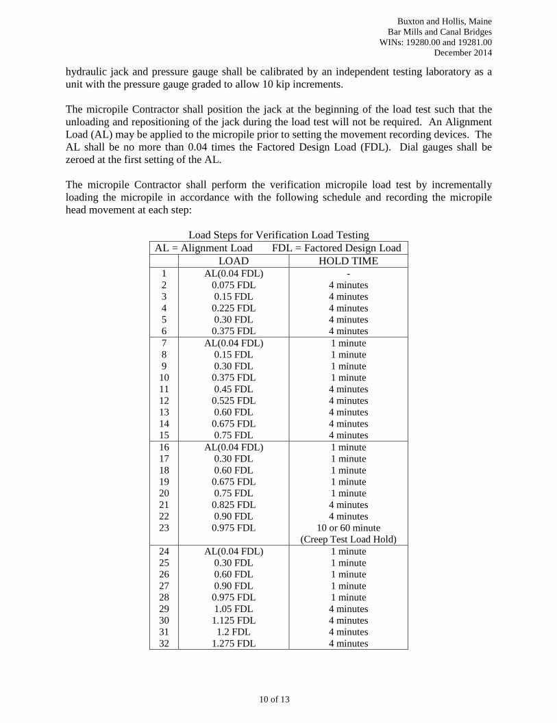
hydraulic jack and pressure gauge shall be calibrated by an independent testing laboratory as a unit with the pressure gauge graded to allow 10 kip increments. The micropile Contractor shall position the jack at the beginning of the load test such that the unloading and repositioning of the jack during the load test will not be required. An Alignment Load (AL) may be applied to the micropile prior to setting the movement recording devices. The AL shall be no more than 0.04 times the Factored Design Load (FDL). Dial gauges shall be zeroed at the first setting of the AL. The micropile Contractor shall perform the verification micropile load test by incrementally loading the micropile in accordance with the following schedule and recording the micropile head movement at each step:
Load Steps for Verification Load Testing AL = Alignment Load FDL = Factored Design Load
LOAD HOLD TIME 1 2 3 4 5 6
AL(0.04 FDL) 0.075 FDL 0.15 FDL 0.225 FDL 0.30 FDL 0.375 FDL
- 4 minutes 4 minutes 4 minutes 4 minutes 4 minutes
7 8 9 10 11 12 13 14 15
AL(0.04 FDL) 0.15 FDL 0.30 FDL 0.375 FDL 0.45 FDL 0.525 FDL 0.60 FDL 0.675 FDL 0.75 FDL
1 minute 1 minute 1 minute 1 minute 4 minutes 4 minutes 4 minutes 4 minutes 4 minutes
16 17 18 19 20 21 22 23
AL(0.04 FDL) 0.30 FDL 0.60 FDL 0.675 FDL 0.75 FDL 0.825 FDL 0.90 FDL 0.975 FDL
1 minute 1 minute 1 minute 1 minute 1 minute 4 minutes 4 minutes
10 or 60 minute (Creep Test Load Hold)
24 25 26 27 28 29 30 31 32
AL(0.04 FDL) 0.30 FDL 0.60 FDL 0.90 FDL 0.975 FDL 1.05 FDL 1.125 FDL 1.2 FDL
1.275 FDL
1 minute 1 minute 1 minute 1 minute 1 minute 4 minutes 4 minutes 4 minutes 4 minutes
10 of 13

Buxton and Hollis, Maine Bar Mills and Canal Bridges
WINs: 19280.00 and 19281.00 December 2014
33 34 35 36 37 38 39 40
1.35 FDL 1.425 FDL 1.5 FDL 1.2 FDL 0.90 FDL 0.60 FDL 0.30 FDL
AL (0.04 FDL)
4 minutes 4 minutes 4 minutes 4 minutes 4 minutes 4 minutes 4 minutes
15 minutes Micropile top movement shall be measured at each load increment. Micropile movement during the creep test shall be measured and recorded at 1, 2, 3, 4, 5, 6, 10, 20, 30, 50, and 60 minutes. The Acceptance Criteria for micropile verification load tests shall be:
1. The micropile shall sustain the axial compression design load (0.75 FDL) in tension with no more than 0.33 inch total vertical movement at the top of the micropile as measured relative to the top of the micropile prior to the start of load testing. If an alignment load is used, then the allowable movement will be reduced by multiplying by a factor of [(0.75 FDL-AL)/0.75FDL].
2. Test micropiles shall have a creep rate at the end of the 0.975 FDL increment which is not greater than 0.04 inches/log cycle time from 1 to 10 minutes or 0.08 inches/log cycle time from 6 to 60 minutes and has a linear or decreasing creep rate throughout the creep load hold period.
3. Failure does not occur by the 1.5 FDL test load. Failure is defined as a slope of the load versus deflection curve (at end of increment) exceeding 0.025 inch/kip.
If the micropile load test fails to meet the design requirements, the cause(s) shall be established, and the micropile design and/or installation methods shall be modified. These modifications include, but are not limited to, installing replacement micropiles, modifying the installation methods, increasing the bond length, regrouting via pre-placed re-grout tubes, or changing the micropile type. Any modification which requires changes to the structure shall have prior review and acceptance of the Resident. The cause for any modifications of design or construction procedures shall be decided in order to appropriately determine any additional cost implications. Any modifications of construction procedures shall be at the micropile Contractor’s expense. Subsequent verification micropiles shall be installed at locations approved by the Resident using the approved modified construction procedures and retested, as detailed previously in this Subsection. If the verification test results meet the acceptance criteria, the Resident shall review and approve the modified design and/or installation methods proposed by the Contractor prior to beginning production micropile installation. The micropile Contractor shall minimize disturbance to the ground surface when placing and removing blocking. The micropile Contractor shall also avoid loading the existing canal and auxiliary spillway retaining walls during any and all load testing. The micropile Contractor will provide the Resident with a written report confirming micropile details and construction procedures within 7 working days after the completion of the pre-production load tests. This written confirmation will either confirm the micropile construction
11 of 13
Buxton and Hollis, Maine Bar Mills and Canal Bridges
WINs: 19280.00 and 19281.00 December 2014
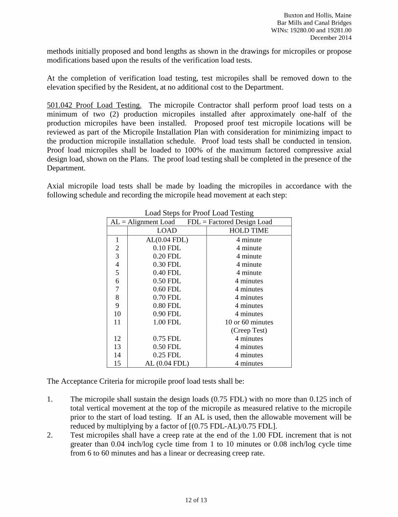
methods initially proposed and bond lengths as shown in the drawings for micropiles or propose modifications based upon the results of the verification load tests. At the completion of verification load testing, test micropiles shall be removed down to the elevation specified by the Resident, at no additional cost to the Department. 501.042 Proof Load Testing. The micropile Contractor shall perform proof load tests on a minimum of two (2) production micropiles installed after approximately one-half of the production micropiles have been installed. Proposed proof test micropile locations will be reviewed as part of the Micropile Installation Plan with consideration for minimizing impact to the production micropile installation schedule. Proof load tests shall be conducted in tension. Proof load micropiles shall be loaded to 100% of the maximum factored compressive axial design load, shown on the Plans. The proof load testing shall be completed in the presence of the Department. Axial micropile load tests shall be made by loading the micropiles in accordance with the following schedule and recording the micropile head movement at each step:
Load Steps for Proof Load Testing AL = Alignment Load FDL = Factored Design Load
LOAD HOLD TIME 1 2 3 4 5 6 7 8 9 10 11
12 13 14 15
AL(0.04 FDL) 0.10 FDL 0.20 FDL 0.30 FDL 0.40 FDL 0.50 FDL 0.60 FDL 0.70 FDL 0.80 FDL 0.90 FDL 1.00 FDL
0.75 FDL 0.50 FDL 0.25 FDL
AL (0.04 FDL)
4 minute 4 minute 4 minute 4 minute 4 minute 4 minutes 4 minutes 4 minutes 4 minutes 4 minutes
10 or 60 minutes (Creep Test)
4 minutes 4 minutes 4 minutes 4 minutes
The Acceptance Criteria for micropile proof load tests shall be: 1. The micropile shall sustain the design loads (0.75 FDL) with no more than 0.125 inch of
total vertical movement at the top of the micropile as measured relative to the micropile prior to the start of load testing. If an AL is used, then the allowable movement will be reduced by multiplying by a factor of [(0.75 FDL-AL)/0.75 FDL].
2. Test micropiles shall have a creep rate at the end of the 1.00 FDL increment that is not greater than 0.04 inch/log cycle time from 1 to 10 minutes or 0.08 inch/log cycle time from 6 to 60 minutes and has a linear or decreasing creep rate.
12 of 13

Buxton and Hollis, Maine Bar Mills and Canal Bridges
WINs: 19280.00 and 19281.00 December 2014
3. Failure does not occur at the 1.00 FDL test load. Failure is defined as a slope of the load versus deflection curve (at the end of the increment) exceeding 0.025 inch/kip.
If a production micropile that is proof load tested fails to meet the Acceptance Criteria, modifications shall be made to the design, the construction procedures or both. These modifications include, but are not limited to, installing replacement micropiles, incorporating micropiles of reduced load capacities, modifying the installation methods, increasing the bond length, or changing the micropile type. Any modification which requires changes to the structure shall have prior review and acceptance of the Resident. Any modifications of construction procedures shall be at the micropile Contractor’s expense. The Resident may elect to proof test an additional micropile in consideration of a failed proof test and/or the circumstances of the modification. 501.05 Method of Measurement. All work related to mobilization and demobilization of any equipment required to satisfactorily complete all micropile installation and load testing shall be measured on a lump sum basis. Micropiles will be measured as the number of accepted micropiles installed including up to one (1) successful verification load test micropile. This measurement shall not include micropiles damaged prior to completion of the work unless remedied to the satisfaction of the Resident. This measurement shall not include verification micropiles that did not meet the acceptance criteria as outlined herein or additional micropiles installed to remediate failed proof load piles. 501.06 Basis of Payment. Drilling Equipment Mobilization. This item shall include the cost of furnishing all labor, materials and equipment necessary for transporting, erecting, dismantling and removing all micropile construction equipment and load testing equipment. The lump sum price for this item will be paid once all equipment is mobilized to the Project site. Micropiles. Payment for micropiles will be paid at the Contract Unit Price per micropile, installed and accepted. The price shall be full compensation for all Work associated with satisfactorily installing the micropiles, including, but not limited to, submittals, shop drawings, Quality Control testing, micropile load testing, and reports. All costs to repair any damage and settlement to adjacent ground and structures shall be incidental to the pay item for micropiles and at no additional cost to the Department. All costs to repair, augment and/or replace all rejected micropiles shall be incidental to the pay item for micropiles and at no additional cost to the Department. Micropiles that fail to meet the Acceptance Criteria will be rejected and no payment will be made for these micropiles. Separate payment will not be made for advancing through boulders and obstructions, but will be considered incidental to the micropile pay item.. There will be no extra payment for grout overruns.
Payment will be made under: Pay Item: Pay Unit 501.804 Drilling Equipment Mobilization - Micropiles Lump Sum 501.220 Micropiles Each
13 of 13


