31
BWR Description Jacopo Buongiorno Associate Professor of Nuclear Science and Engineering 22.06: Engineering of Nuclear Systems 1

BWR Description
Jacopo BuongiornoAssociate Professor of Nuclear Science and Engineering
22.06: Engineering of Nuclear Systems
1

Boiling Water Reactor (BWR)
Public domain image by US NRC.
2

The BWR is a Direct Cycle PlantThe BWR is a Direct Cycle Plant
S t MP 7 136 System pressure, MPa 7.136 Core thermal power, MWth 3323 Electric power, MWe 1130 Thermal efficiency, % 34 Vessel ID / Thickness / Height, m 6.4 / 0.16 / 22g , Core shroud diameter, m 5.2 Number of fuel assemblies 764 Core mass flow rate, kg/s 13702 Core inlet temperature, ºC 278.3 Core outlet temperature, ºC 287.2 Core exit quality, % 13.1 Feedwater flow rate, kg/s 1820 Feedwater temperature, ºC 220 St fl t k / 1820Steam flow rate, kg/s 1820 Steam temperature, ºC 287.2 Core power density, kW/L 50.5 Core flow bypass 14 %
A.V. Nero, Jr., A Guidebook to Nuclear Reactors, 1979
Image by MIT OpenCourseWare.
Steam line
Reactor vessel
Feedwater
Core
Feedpumps
Demineralizer
Condensatepumps
Turbine generator
Separators &dryers
Heater
Recirculation pumps
3

[MPa]
Phase Diagram of WaterPhase Diagram of Water
Pressure
7 37.3
Vapor Vapor
278 288 Temperature [C]
Saturation line
BWR core
Liquid
4

BWR Core
5

BWR Core LayoutBWR Core Layout0°
Fuel Bundle Control Cell Bundle Peripheral Bundle Control BladeControl Blade
270° 90°
Typical Control Cell Core Layout 180°180
© source unknown All rights reserved. This content is excluded from our Creative Commons license. For more information, see http://ocw.mit.edu/fairuse.6

BWR Fuel AssemblyBWR Fuel Assembly
Upper Tie Plate
Channel Fastener
Assembly
Fuel Cladding
Fuel Claddding Expansion
Spring
Fuel Channel
Lower
Plenum Spring
Tie Plate
Nose Piece Fuel Rod
Fuel Pellet
F l bli h d t ll t P07.cvs
Single bundle 3D view uel assemblies have a duct wall to prevent vapor radial drifting
Image by MIT OpenCourseWare. © source unknown All rights reserved. This content is excluded from our Creative Commons license. For more information, see http://ocw.mit.edu/fairuse.
F
7

BWR Fuel AssembliesBWR Fuel Assemblies
Image by MIT OpenCourseWare.
8

Fuel Assembly Parameters for 9x9 Fuel AssemblyParameter Value Fuel Pellet OD (mm) 9.55 Fuel Pin OD (mm) 11.18 Clad Thickness (mm) 0.71 Fuel Pin Pitch (mm) 14.27 Active Fuel rod height (mm) 3707.9 Total Fuel Rod height (mm) 4178.7 Part Length Rod Height (mm) 2436 Fuel Pins / Water Rods per Fuel Assemblyp y 74/2 Number of Part Length Rods 8 Inner/Outer diameter of the water rods (mm) 23.37/24.89 Duct Thickness (mm) 2.54 Clearance between duct and peripheral fuel rods (mm) 3.53 Clearance between water rods and fuel rods (mm)( ) 1.79 Assembly Outer Dimension (mm) 137.54 Inter-Assembly Gap (mm) 14.86 Average Linear Power (kW/m) 16.46 Pressure Drop (kPa) 160 Average enrichment (wt%) Average enrichment (wt%) 4.314.31 Average Discharge Burnup (GWd/t) 56 Refueling scheme 4 batches Number of rods with gadolinia 8 Gadolinia concentration (wt%) 5 Hydrogen to Heavy Metal Ratio Hydrogen to Heavy Metal Ratio 4 53 4.53 Void Coefficient (pcm/% void) -144 Fuel Temperature Coefficient (pcm/K) -1.7 Approximate Assembly Weight (kg) 281
9

Control BladeControl Blade
Image removed due to copyright restrictions.
Image by MIT OpenCourseWare.
10

BWR Control Rod Drive SystemBWR Control Rod Drive System
Image by MIT OpenCourseWare.
11

BWR SPATIAL CORE PROPERTIES(WITH CONTROL RODS PARTIALLY INSERTED)
Relative power
Average void fractionCritical heat flux ratioin hot channel x0.1
1.5
1.0
0.5
00 0.1 0.2 0.3 0.4 0.5 0.6 0.7 0.8 0.9 1.0
Relative axial length
Rel
ativ
e pa
ram
eter
s
Bottom of core Top of core
Image by MIT OpenCourseWare.
12

POWER IN FRESH FUEL ASSEMBLY AS ADJACENTCOCONTROOL ROD ISS WITHDRAAWN TOOWARD BOOTTOMO A O
“BWR/6: General Description of a BWR,” GE, 1980.
Nodal power normalized to 1.0 over the core.
(Bottom).2
.4
.6
.8
1.0
1.2
1.4
1.6
1.8
(Top)Axial Length of Fuel
17 25 33 42 50 58 0Percent FullInsertion
67
Rel
ativ
e Po
wer
670
Image by MIT OpenCourseWare.
13

Connection of BWR Core Desiggn to Neutronics
Why are the fuel rods spaced out more in a BWR than in a PWR?Why are the fuel rods spaced out more in a BWR than in a PWR?
Why is the core power density lower in a BWR core than in a PWR?
What is the purpose of spatial fuel enrichment zoning throughout a BWR fuel assembly?
What function do the water rods perform?
h h l d i d f h b f hWhy are the BWR control rods inserted from the bottom of the core?
Can dissolved boron be used as a means to control reactivity in a BWR core?
14

BWR Bundle Design AdvancesBWR Bundle Design AdvancesExtended burnup features More fuel ppins ((1010)) for a lower
heat flux
Heavier fuel loadings
Improved mechanical performance “Barrier” cladding
Low growth, wear resistant materials
Improved operational performanceImproved operational performance Natural uranium blankets
Flow mixing grids to enhance margin to critical power
Part-Length Fuel Rods (Stability, SDM)
Large Central Water Channels (Stability,y, SDM ))(
Sophisticated poison & enrichment zoning
Control Rod
Fuel RodPart Length Fuel Rod
Image by MIT OpenCourseWare.
© source unknown All rights reserved. This content is excluded from our Creative Commons license. For more information, see http://ocw.mit.edu/fairuse.
15

BWR Vessel and VesselBWR Vessel and VesselInternals
16
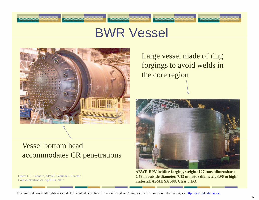
BWR VesselBWR Vessel
Vessel bottom head accommodates CR penetrations
Large vessel made of ring forgings to avoid welds in the core region
ABWR RPV beltline forging, weight: 127 tons; dimensions: From: L.E. Fennern, ABWR Seminar – Reactor, 7.48 m outside diameter, 7.12 m inside diameter, 3.96 m high; Core & Neutronics. April 13, 2007. material: ASME SA 508, Class 3 EQ.
© source unknown. All rights reserved. This content is excluded from our Creative Commons license. For more information, see http://ocw.mit.edu/fairuse.17

BWR Vessel InternalsBWR Vessel Internals
From: V. Shah, P. MacDonald, Aging and Life Extension of Major LWR Components, 1993.
© Elsevier. All rights reserved. This content is excluded from our Creative Commons license. For more information, see http://ocw.mit.edu/fairuse.Source: Shah, V. N. and P. E. MacDonald. Aging and Life Extension of Major Light Water Reactor Components. Atlanta, GA: Elsevier Science, 1993. ISBN: 9780444894489. 18

Steam Separators
Steam Dome
Steam Dryer Height
Steam Dryers
Drain Pipes Steam + Droplets
From: V. Shah, P. MacDonald, Aging and Life Extension of Major LWR Components, 1993.
© Elsevier. All rights reserved. This content is excluded from our Creative Commons license. For more information, see http://ocw.mit.edu/fairuse.Source: Shah, V. N. and P. E. MacDonald. Aging and Life Extension of Major Light Water Reactor Components. Atlanta, GA: Elsevier Science, 1993. ISBN: 9780444894489. 19

BWR Recirculation System
20

BWR Recirculation SystemBWR Recirculation System BWR/6 ABWR ESBWR
Steam Dryers
Steam Flow to Turbine
Steam Separators Feed Flow
from Condenser g o
Jet Pump Core
Driving Flow
RecirculationPump
Ten internal Relies on natural External recirculation pumps + jet pumps recirculation pumps circulation
Courtesy of GE Hitachi Nuclear Systems. Used with permission.21

Traditional BWR vs ABWR and ESBWRTraditional BWR vs ABWR and ESBWRParameter
Power (MWt/MWe) 3293/1098
21.9/6.4
764
3.7
50
185/LP
9
2
1E-5
115 150
1E-6
3
9
193/LP
2(large)
54.2
3.7
800
21.8/6.4
3900/1360 3926/1350
21.1/7.1
872
3.7
51
10
205/FM
18
3
1E-7 1E-7
269/FM
3.0
54
1132
27.7/7.1
4500/1550
ESBWR
160 <100
Zero
Zero
Zero2(large)
BWR/4-Mk I(Browns Ferry 3)
BWR/6-Mk III(Grand Gulf) ABWR
Vessel height/dia. (m)
Fuel bundles (number)
Active fuel height (m)
Power density (kW/L)
Recirculation pumps
Number of CRDs/type
Safety system pumps
Safety diesel generator
Core damage freq./yr
Safety Bldg Vol (m3/MWe)
Image by MIT OpenCourseWare.
22

Suction Flow Drive Flow 2
BWR/6 Recirculation FlowBWR/6 Recirculation Flow1 unit
Steam Dryers
Steam Flow to Turbine 1 unit
Steam Separators
Driving Flow
Feed Flow from Turbine 1 unit
5 units
Jet Pump Core
4 units
Recirculation Pump
2 units 6 units
Jet Pump M-Ratio = Suction Flow / Drive Flow = 2/
Courtesy of GE Hitachi Nuclear Systems. Used with permission.
23
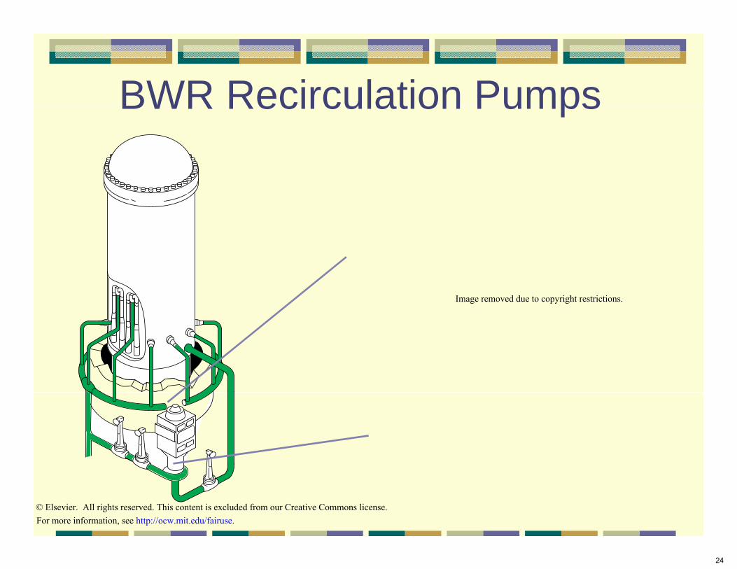
BWR Recirculation PumpsBWR Recirculation Pumps
Image removed due to copyright restrictions.
© Elsevier. All rights reserved. This content is excluded from our Creative Commons license. For more information, see http://ocw.mit.edu/fairuse.
24

BWR Jet PumpsBWR Jet PumpsHolddown Assembly
Inlet
Jet Pump Nozzle AssemblyRestrainers and S tSupportsCore ShroudMixer
Restrainers and Supports
Inlet Riser
pp
Reactor Vessel WallCore Support
Diffuser and Tail PipeRecirculation InletRecirculation Inlet Nozzle – 1 per Jet Pump Riser
© Elsevier. All rights reserved. This content is excluded from our Creative Commons license. For more information, see http://ocw.mit.edu/fairuse.25

BWR Balance Of Plant (BOP)
26

eate s
BWR Power Cyycle Moisture Separator
and Reheater Steam
Reactor Vessel Generator
LP LPHPTurbine
Separatorsand Dryers
Core
Feedwater Extraction Steam
Recirc Pump
Recirc Pump
Feed Pumps
Demineralizers Extraction Steam
p p
Drain
Heaters
Heaters
Condensate Pumps
Condenser
Pumps
“BWR/6, General Description of a BWR,” GE, 1980
Courtesy of GE Hitachi Nuclear Systems. Used with permission.
27

Radioactive SteamRadioactive Steam Entire Power Conversion System becomes Radioactive Shi ldi i N d dShielding is Needed
Reaction products from water: O16 + n N16 + H1, T1/2 = 7.2 s; , 1/2O17 + n N17 + H1, T1/2 = 4.2 s; , O18 + n O19 F19, T1/2 = 29 s; ,
Activation of corrosion pproducts: Fe54 + n Fe55, T1/2 = 2.7 y;
Fe58 + n Fe59, T1/2 = 44.6 d; , Co59 + nn CoCo60, T, T1/2 = 5.3 y; , Co 5.3 y; ,
Ni58 + n Ni59, T1/21/2= 8x10⁴ y; ,
Ni62 + n Ni63, T1/2 = 100 y; ,
28

Air Ejjector
Removes Anyy Gases in Coolant Downstream of Condenser
They Must be Held Up and Stabilized
Nobel Gas Fission Products Escaped from Faulty Fuel Pins(Xe, Kr isotopes)
Xe135 Cs135 + b-Xe Cs b + g, T1/2 = 9.2 h g, T 9.2 h1/2Kr88 Rb88 + b- + g, T1/2 = 2.8 h
Kr85 Rb85 + b-1 + g, T1/2 = 10.7 y
H2 from Radiolysis of H2O N Isotopes Produced by (O + n) Reactions Gases Leaking into CondenserGases Leaking into Condenser
29

BWR safety systems andBWR safety systems andcontainment to be discussed
later in the course
30

MIT OpenCourseWarehttp://ocw.mit.edu
22.06 Engineering of Nuclear SystemsFall 2010
For information about citing these materials or our Terms of Use, visit: http://ocw.mit.edu/terms.


