15
: http://www.ctarl.org.tw /BX4AA 1 WRC-03 .
| Date post: | 09-Sep-2018 |
| Category: |
Documents |
| Upload: | hoangnguyet |
| View: | 214 times |
| Download: | 0 times |

!"#$%&'()*+,!"#$%%&'&( )*+,-. /&0 1 00 2
34#$&%( 00&560&7 8 '&& 9:;#$&%( 00&500<=
>?@AB1#CDEFCGBHIJ K LMN1OP>?
Q" : http://www.ctarl.org.tw
!"/BX4AA#$
1% &'()*+,-./0123456789WRC-03:;<=>?@A-BC>DEFGHIJKL.

0MN
()*+,-./01234567
1. O7PQ/012R+,-.56>ST12GUVW)XY)RZ[/0\]R^_3456`7Qa
2. `IW)bcXY)TdefRZ[g]R/012>hijklm/012n4T+,-.34UVoW)p
qr1sRtuv,a
3. wox56huyl@z{|}()QP(EPIRB)*~>z{��12G>��Rz{12G>�s�12G>�
��*~��z{���r�lR��12Ga
4. �@����lR�?>�L�����j7���zR56>ul@m���R56��vy�R� ¡()
*J¢£¤r¥¦§>��z56¨�©?ªHREFGH«¬¤®LRa
5. ¯@()*�L*~>°Vª�±²R�³´µv¶>u·¸mx/012R+¹ºl34a
APPENDIX 3 (Rev.WRC-03)
Tables of maximum permitted power levels for spurious
or spurious domain emissions
(See Article 3)
1 The following sections indicate the maximum permitted levels of certain unwanted
emissions, in terms of power as indicated in the tables, of components supplied by a transmitter to the
antenna transmission line. Section I, which provides spurious emission limits, is applicable until
1 January 2012 to transmitters installed on or before 1 January 2003; Section II, which limits emissions in
the spurious domain, is applicable to transmitters installed after 1 January 2003 and to all transmitters
after 1 January 2012. The provisions of No. 4.5 apply to unwanted emissions not covered in Sections I
and II.
2 Spurious and spurious domain emissions (covered by Sections I and II) from any part of the
installation, other than the antenna and its transmission line, shall not have an effect greater than would
occur if this antenna system were supplied with the maximum permitted power at the frequency of that
emission.
3 These levels shall not, however, apply to emergency position-indicating radiobeacon
(EPIRB) stations, emergency locator transmitters, ships’ emergency transmitters, lifeboat transmitters,
survival craft stations or maritime transmitters when used in emergency situations.
4 For technical or operational reasons, more stringent levels than those specified may be
applied to protect specific services in certain frequency bands. The levels applied to protect these
services, such as safety and passive services, shall be those agreed upon by the appropriate world
radiocommunication conference. More stringent levels may also be fixed by specific agreement between
the administrations concerned. Additionally, special consideration of transmitter spurious or spurious
domain emissions may be required for the protection of safety services, radio astronomy and space

services using passive sensors. Information on the levels of interference detrimental to radio astronomy,
Earth exploration satellites and meteorological passive sensing is given in the most recent version of
Recommendation ITU-R SM.329.
5 Spurious and spurious domain emission limits (covered by Sections I and II) for combined
radiocommunication and information technology equipment are those for the radiocommunication
transmitters. (WRC-03)

Section I – Spurious emission limits for transmitters installed on
or before 1 January 2003 (valid until 1 January 2012)
6 Radar systems are exempt from spurious emission limits under this Section. The lowest
practicable power of spurious emission should be achieved. (WRC-2000)
TABLE I
Attenuation values and absolute mean power levels used to calculate maximum
permitted spurious emission power levels for use with radio equipment
Frequency band containing the
assignment
(lower limit exclusive,
upper limit inclusive)
For any spurious component, the attenuation (mean
power within the necessary bandwidth relative to the
mean power of the spurious component concerned)
shall be at least that specified below and the absolute
mean power levels given shall not be exceeded1
9 kHz to 30 MHz 40 dB
50 mW 2, 3, 4
30 MHz to 235 MHz
– mean power above 25 W 60 dB
1 mW 5
– mean power 25 W or less 40 dB
25 W
235 MHz to 960 MHz
– mean power above 25 W 60 dB
20 mW 6, 7
– mean power 25 W or less 40 dB
25 W 6, 7
960 MHz to 17.7 GHz
– mean power above 10 W 50 dB
100 mW 6, 7, 8, 9
– mean power 10 W or less 100 W 6, 7, 8, 9
Above 17.7 GHz The lowest possible values achievable shall be employed
(see Recommendation 66 (Rev.WRC-2000)*).
1 When checking compliance with the provisions of the Table, it shall be verified that the
bandwidth of the measuring equipment is sufficiently wide to accept all significant
components of the spurious emission concerned.
2 For mobile transmitters which operate below 30 MHz, any spurious component shall have
an attenuation of at least 40 dB without exceeding the value of 200 mW, but every effort
should be made to comply with the level of 50 mW wherever practicable.
3 For transmitters of a mean power exceeding 50 kW which can operate on two or more
frequencies covering a frequency range approaching an octave or more, while a reduction
below 50 mW is not mandatory, a minimum attenuation of 60 dB shall be provided.

TABLE I (end)
4 For hand-portable equipment of mean power less than 5 W, the attenuation shall be 30 dB,
but every practicable effort should be made to attain 40 dB attenuation.
5 Administrations may adopt a level of 10 mW provided that harmful interference is not
caused.
6 Where several transmitters feed a common antenna or closely spaced antennas on neigh-
bouring frequencies, every practicable effort should be made to comply with the levels
specified.
7 Since these levels may not provide adequate protection for receiving stations in the radio
astronomy and space services, more stringent levels might be considered in each individual
case in the light of the geographical position of the stations concerned.
8 These levels are not applicable to systems using digital modulation techniques, but
may be used as a guide. Values for these systems may be provided by the relevant
ITU-R Recommendations, when available (see Recommendation 66 (Rev.WRC-2000)*).
9 These levels are not applicable to stations in the space services, but the levels of their
spurious emissions should be reduced to the lowest possible values compatible with the
technical and economic constraints to which the equipment is subject. Values for these
systems may be provided by the relevant ITU-R Recommendations, when available
(see Recommendation 66 Rev.WRC-2000)*).
* Note by the Secretariat: This Recommendation was abrogated by WRC-03.
Section II – Spurious domain emission limits for transmitters installed after 1 January 2003 and for
all transmitters after 1 January 2012 (WRC-03)
Application of these limits
7 The frequency range of the measurement of spurious domain emissions is from 9 kHz to
110 GHz or the second harmonic if higher. (WRC-03)
8 Except as provided in § 9 and 10 of this Appendix, the spurious domain emission levels are
specified in the following reference bandwidths:
– 1 kHz between 9 kHz and 150 kHz
– 10 kHz between 150 kHz and 30 MHz
– 100 kHz between 30 MHz and 1 GHz
– 1 MHz above 1 GHz. (WRC-03)
9 The reference bandwidth of all space service spurious domain emissions should be
4 kHz. (WRC-03)
10 For radar systems, the reference bandwidths for specifying spurious domain emission levels
should be calculated for each particular system. Thus, for the four general types of radar pulse modulation
utilized for radionavigation, radiolocation, acquisition, tracking and other radiodetermination functions,
the reference bandwidth values are determined using the following:
– for a fixed-frequency, non-pulse-coded radar, the reciprocal of the radar pulse length, in seconds
(e.g. if the radar pulse length is 1 s, then the reference bandwidth is 1/(1 s) 1 MHz);
– for a fixed-frequency, phase-coded pulsed radar, the reciprocal of the phase chip length, in seconds
(e.g. if the phase-coded chip is 2 s long, then the reference bandwidth is 1/(2 s) 500 kHz);
– for a frequency modulated (FM) or chirped radar, the square root of the quantity obtained by
dividing the chirp bandwidth in MHz by the pulse length, in s (e.g. if the FM is from 1 250 MHz
to 1 280 MHz, i.e. 30 MHz, during the pulse length of 10 s, then the reference bandwidth is
(30 MHz/10 s)1/2 1.73 MHz);
– for radars operating with multiple waveforms, the reference bandwidth for specifying spurious
domain emission levels is determined empirically from observations of the radar emission and is
obtained following the guidance given in the most recent version of Recommendation ITU-R
M.1177.
In the case of radars, for which the bandwidth, as determined using the method above, is greater than
1 MHz, a reference bandwidth of 1 MHz should be used. (WRC-03)
10bis Guidance regarding the methods of measuring spurious domain emissions is given in the
most recent version of Recommendation ITU-R SM.329. The e.i.r.p. method specified in this
Recommendation should be used when it is not possible to accurately measure the power supplied to the
antenna transmission line, or for specific applications where the antenna is designed to provide significant
attenuation in the spurious domain. Additionally, the e.i.r.p. method may need some modification for
special cases. Specific guidance regarding the methods of measuring spurious domain emissions from
radar systems is given in the most recent version of Recommendation ITU-R M.1177.
To improve measurement accuracy, sensitivity and efficiency, the resolution bandwidth in which spurious
domain emissions are measured can be different from the reference bandwidth used for specifying
spurious domain emission levels. (WRC-03)
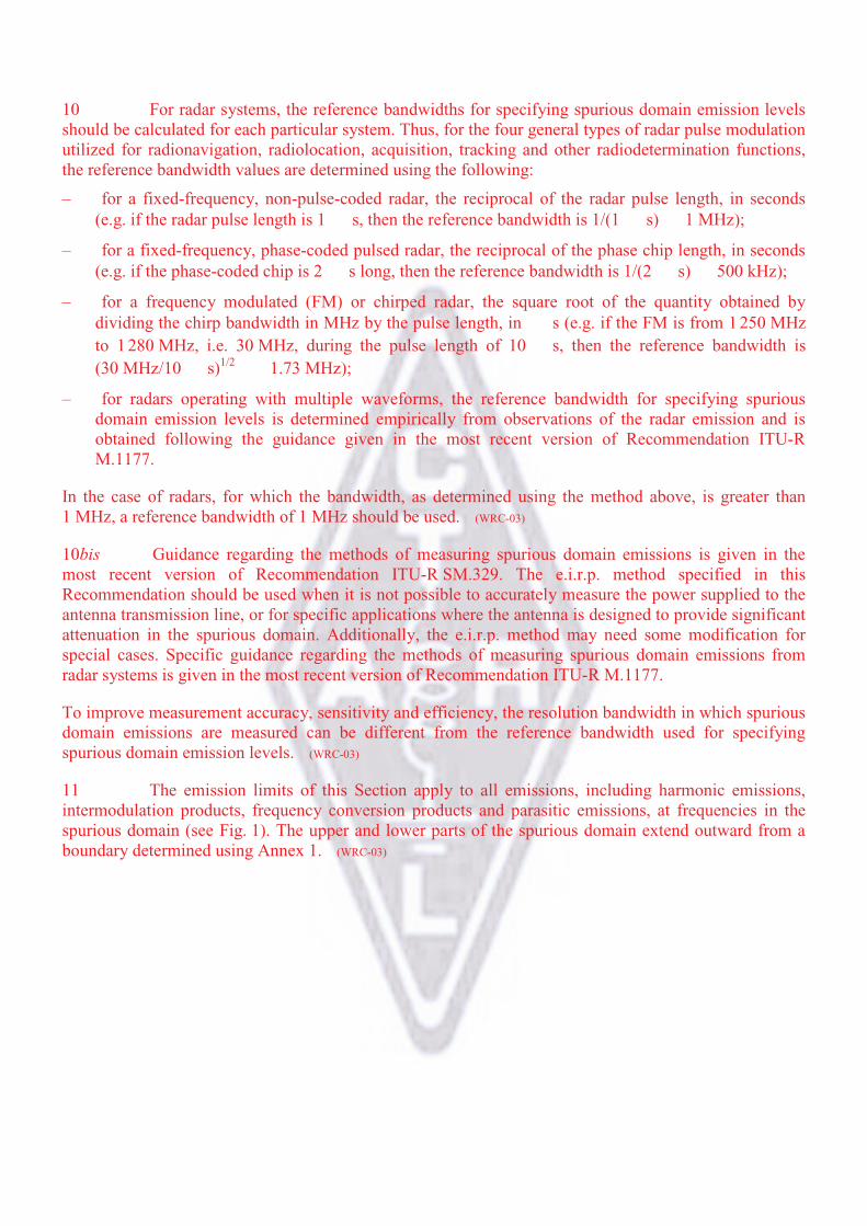
11 The emission limits of this Section apply to all emissions, including harmonic emissions,
intermodulation products, frequency conversion products and parasitic emissions, at frequencies in the
spurious domain (see Fig. 1). The upper and lower parts of the spurious domain extend outward from a
boundary determined using Annex 1. (WRC-03)
11bis (SUP - WRC-03)
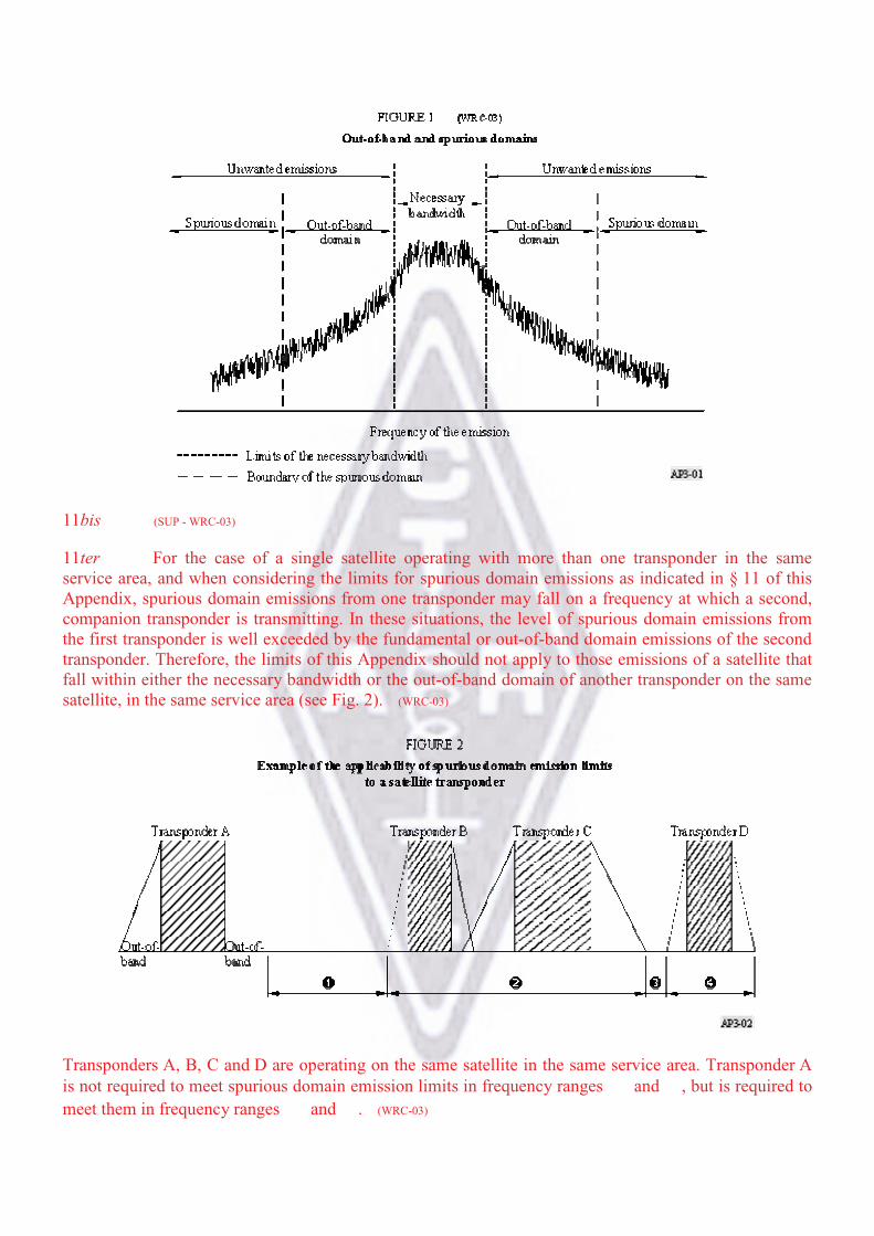
11ter For the case of a single satellite operating with more than one transponder in the same
service area, and when considering the limits for spurious domain emissions as indicated in § 11 of this
Appendix, spurious domain emissions from one transponder may fall on a frequency at which a second,
companion transponder is transmitting. In these situations, the level of spurious domain emissions from
the first transponder is well exceeded by the fundamental or out-of-band domain emissions of the second
transponder. Therefore, the limits of this Appendix should not apply to those emissions of a satellite that
fall within either the necessary bandwidth or the out-of-band domain of another transponder on the same
satellite, in the same service area (see Fig. 2). (WRC-03)
Transponders A, B, C and D are operating on the same satellite in the same service area. Transponder A
is not required to meet spurious domain emission limits in frequency ranges and , but is required to
meet them in frequency ranges and . (WRC-03)

12 Examples of applying 43 10 log (P) to calculate attenuation requirements
Where specified in relation to mean power, spurious domain emissions are to be at least x dB below the
total mean power P, i.e. – x dBc. The power P (W) is to be measured in a bandwidth wide enough to
include the total mean power. The spurious domain emissions are to be measured in the reference
bandwidths given in the relevant ITU-R Recommendations. The measurement of the spurious domain
emission power is independent of the value of necessary bandwidth. Because the absolute emission power
limit, derived from 43 10 log (P), can become too stringent for high-power transmitters, alternative
relative powers are also provided in Table II.
Example 1
A land mobile transmitter, with any value of necessary bandwidth, must meet a spurious domain emission
attenuation of 43 10 log (P), or 70 dBc, whichever is less stringent. The reference bandwidths used
for specifying spurious domain emission levels are provided in § 8 to 10 of this Appendix. Applying this
in the frequency range between 30 MHz and 1 GHz gives a reference bandwidth of 100 kHz.
With a measured total mean power of 10 W:
– Attenuation relative to total mean power 43 10 log (10) 53 dBc.
– The 53 dBc value is less stringent than the 70 dBc, so the 53 dBc value is used.
– Therefore: Spurious domain emissions must not exceed 53 dBc in a 100 kHz bandwidth, or
converting to an absolute level, they must not exceed 10 dBW – 53 dBc –43 dBW in a 100 kHz
reference bandwidth.
With a measured total mean power of 1 000 W:
– Attenuation relative to total mean power 43 10 log (1 000) 73 dBc.
– The 73 dBc value is more stringent than the 70 dBc limit, so the 70 dBc value is used.
– Therefore: Spurious domain emissions must not exceed 70 dBc in a 100 kHz bandwidth, or
converting to an absolute level, they must not exceed 30 dBW – 70 dBc _40 dBW in a 100 kHz
reference bandwidth. (WRC-03)
Example 2
A space service transmitter with any value of necessary bandwidth must meet a spurious domain emission
attenuation of 43 10 log (P), or 60 dBc, whichever is less stringent. To measure

spurious domain emissions at any frequency, Note 10 to Table II indicates using a reference bandwidth of
4 kHz.
With a measured total mean power of 20 W:
– Attenuation relative to total mean power 43 10 log (20) 56 dBc.
– The 56 dBc value is less stringent than the 60 dBc limit, so the 56 dBc value is used.
– Therefore: Spurious domain emissions must not exceed 56 dBc in a 4 kHz reference bandwidth, or
converting to an absolute level, they must not exceed 13 dBW – 56 dBc _43 dBW in a 4 kHz
reference bandwidth. (WRC-03)
TABLE II (WRC-03)
Attenuation values used to calculate maximum permitted
spurious domain emission power levels for
use with radio equipment
Service category in accordance with
Article 1, or equipment type15
Attenuation (dB) below the power
supplied to the antenna transmission line
All services except those services quoted below: 43 10 log (P), or 70 dBc, whichever is less stringent
Space services (earth stations)10, 16 43 10 log (P), or 60 dBc, whichever is less stringent
Space services (space stations)10, 17 43 10 log (P), or 60 dBc, whichever is less stringent
Radiodetermination14 43 10 log (PEP), or 60 dB, whichever is less stringent
Broadcast television11 46 10 log (P), or 60 dBc, whichever is less stringent,
without exceeding the absolute mean power level of 1 mW
for VHF stations or 12 mW for UHF stations. However,
greater attenuation may be necessary on a case by case
basis
Broadcast FM 46 + 10 log (P), or 70 dBc, whichever is less stringent; the
absolute mean power level of 1 mW should not be
exceeded
Broadcasting at MF/HF 50 dBc; the absolute mean power level of 50 mW should
not be exceeded
SSB from mobile stations12 43 dB below PEP
Amateur services operating below 30 MHz (including
those using SSB)16
43 10 log (PEP), or 50 dB, whichever is less stringent
Services operating below 30 MHz, except space,
radiodetermination, broadcast, those using SSB from
mobile stations, and amateur12
43 10 log (X), or 60 dBc, whichever is less stringent,
where X PEP for SSB modulation, and X P for
other modulation
Low-power device radio equipment13 56 10 log (P), or 40 dBc, whichever is less stringent
Emergency transmitters18 No limit
TABLE II (end) (WRC-03)
P: mean power in watts supplied to the antenna transmission line, in accordance with No. 1.158. When burst
transmission is used, the mean power P and the mean power of any spurious domain emissions are measured
using power averaging over the burst duration.
PEP: peak envelope power in watts supplied to the antenna transmission line, in accordance with No. 1.157.
dBc: decibels relative to the unmodulated carrier power of the emission. In the cases which do not have a carrier,
for example in some digital modulation schemes where the carrier is not accessible for measurement, the
reference level equivalent to dBc is decibels relative to the mean power P.
10 Spurious domain emission limits for all space services are stated in a 4 kHz reference bandwidth.
11 For analogue television transmissions, the mean power level is defined with a specified video signal
modulation. This video signal has to be chosen in such a way that the maximum mean power level (e.g. at the
video signal blanking level for negatively modulated television systems) is supplied to the antenna
transmission line.
12 All classes of emission using SSB are included in the category “SSB”.
13 Low-power radio devices having a maximum output power of less than 100 mW and intended for
short-range communication or control purposes; such equipment is in general exempt from individual
licensing.
14 For radiodetermination systems (radar as defined by No. 1.100), spurious domain emission attenuation (dB)
shall be determined for radiated emission levels, and not at the antenna transmission line. The measurement
methods for determining the radiated spurious domain emission levels from radar systems should be guided
by the most recent version of Recommendation ITU-R M.1177. (WRC-03)
15 In some cases of digital modulation (including digital broadcasting), broadband systems, pulsed modulation
and narrow-band high-power transmitters for all categories of services, there may be difficulties in meeting
limits close to 250% of the necessary bandwidth.
16 Earth stations in the amateur-satellite service operating below 30 MHz are in the service category “Amateur
services operating below 30 MHz (including those using SSB)”. (WRC-2000)
17 Space stations in the space research service intended for operation in deep space as defined by No. 1.177 are
exempt from spurious domain emission limits. (WRC-03)
18 Emergency position-indicating radio beacon, emergency locator transmitters, personal location beacons,
search and rescue transponders, ship emergency, lifeboat and survival craft transmitters and emergency land,
aeronautical or maritime transmitters. (WRC-2000)
ANNEX 1 (WRC-03)
Determination of the boundary between the
out-of-band and spurious domains
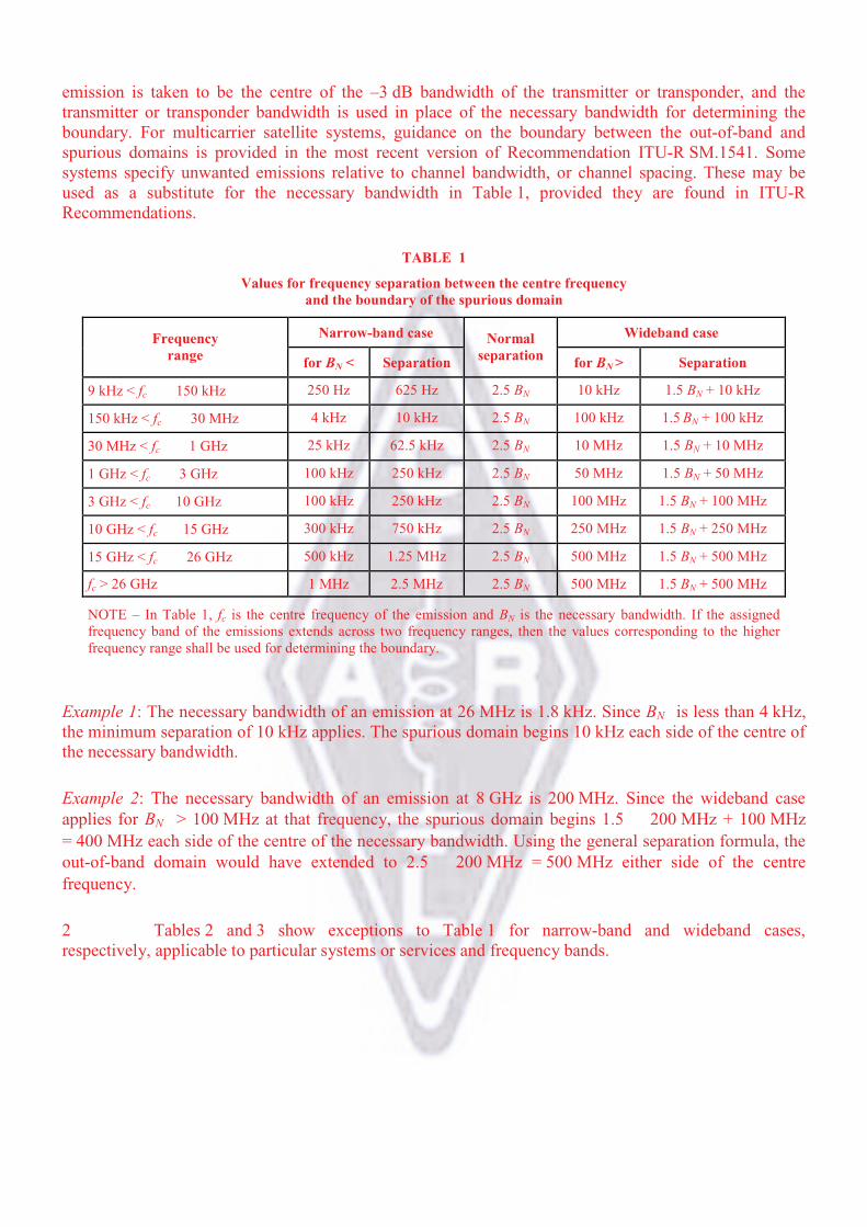
1 Except as provided below, the boundary between the out-of-band and spurious domains
occurs at frequencies that are separated from the centre frequency of the emission by the values shown in
Table 1. In general, the boundary, on either side of the centre frequency, occurs at a separation of 250%
of the necessary bandwidth, or at 2.5 BN, as shown in Table 1. For most systems, the centre frequency of
the emission is the centre of the necessary bandwidth. For multichannel or multicarrier
transmitters/transponders, where several carriers may be transmitted simultaneously from a final output
amplifier or an active antenna, the centre frequency of the
emission is taken to be the centre of the –3 dB bandwidth of the transmitter or transponder, and the
transmitter or transponder bandwidth is used in place of the necessary bandwidth for determining the
boundary. For multicarrier satellite systems, guidance on the boundary between the out-of-band and
spurious domains is provided in the most recent version of Recommendation ITU-R SM.1541. Some
systems specify unwanted emissions relative to channel bandwidth, or channel spacing. These may be
used as a substitute for the necessary bandwidth in Table 1, provided they are found in ITU-R
Recommendations.
TABLE 1
Values for frequency separation between the centre frequency
and the boundary of the spurious domain
Narrow-band case Wideband case Frequency
range for BN < Separation
Normal
separation for BN > Separation
9 kHz < fc 150 kHz 250 Hz 625 Hz 2.5 BN 10 kHz 1.5 BN + 10 kHz
150 kHz < fc 30 MHz 4 kHz 10 kHz 2.5 BN 100 kHz 1.5 BN + 100 kHz
30 MHz < fc 1 GHz 25 kHz 62.5 kHz 2.5 BN 10 MHz 1.5 BN + 10 MHz
1 GHz < fc 3 GHz 100 kHz 250 kHz 2.5 BN 50 MHz 1.5 BN + 50 MHz
3 GHz < fc 10 GHz 100 kHz 250 kHz 2.5 BN 100 MHz 1.5 BN + 100 MHz
10 GHz < fc 15 GHz 300 kHz 750 kHz 2.5 BN 250 MHz 1.5 BN + 250 MHz
15 GHz < fc 26 GHz 500 kHz 1.25 MHz 2.5 BN 500 MHz 1.5 BN + 500 MHz
fc > 26 GHz 1 MHz 2.5 MHz 2.5 BN 500 MHz 1.5 BN + 500 MHz
NOTE – In Table 1, fc is the centre frequency of the emission and BN is the necessary bandwidth. If the assigned
frequency band of the emissions extends across two frequency ranges, then the values corresponding to the higher
frequency range shall be used for determining the boundary.
Example 1: The necessary bandwidth of an emission at 26 MHz is 1.8 kHz. Since BN is less than 4 kHz,
the minimum separation of 10 kHz applies. The spurious domain begins 10 kHz each side of the centre of
the necessary bandwidth.
Example 2: The necessary bandwidth of an emission at 8 GHz is 200 MHz. Since the wideband case
applies for BN > 100 MHz at that frequency, the spurious domain begins 1.5 200 MHz + 100 MHz
= 400 MHz each side of the centre of the necessary bandwidth. Using the general separation formula, the
out-of-band domain would have extended to 2.5 200 MHz = 500 MHz either side of the centre
frequency.
2 Tables 2 and 3 show exceptions to Table 1 for narrow-band and wideband cases,
respectively, applicable to particular systems or services and frequency bands.

TABLE 2
Narrow-band variations for particular systems or services and frequency bands
Narrow-band case
System or service Frequency range for BN <
(kHz)
Separation
(kHz)
14 kHz-1.5 MHz 20 50(1)
PT � 50 W 30 75(2)Fixed service
1.5-30 MHz PT > 50 W 80 200
(2)
(1) The separation value is based on an assumption that the maximum value of the necessary bandwidth is
about 3 kHz for the frequency range 14 kHz-1.5 MHz. The separation value of 50 kHz is extremely
large as compared with the necessary bandwidth. This is because unwanted emissions of high power
transmitters under modulated conditions have to be below the spurious limit (70 dBc) at the boundary
between the out-of-band and spurious domains.
(2) PT is the transmitter power. The separation values are based on an assumption that the maximum value
of the necessary bandwidth is about 12 kHz for the frequency range 1.5-30 MHz. The separation value
of 200 kHz for PT > 50 W is extremely large as compared with the necessary bandwidth. This is because
unwanted emissions of high power transmitters under modulated conditions have to be below the
spurious limit, 70 dBc, at the boundary between the out-of-band and spurious domains. Also, if future
systems in the fixed service operating in this frequency range require a necessary bandwidth larger than
12 kHz, it may become necessary to review the 200 kHz separation.
TABLE 3
Wideband variations for particular systems or services and frequency bands
Wideband case System or service Frequency range
For BN > Separation
Fixed service 14-150 kHz 20 kHz 1.5 BN + 20 kHz
Fixed-satellite
service (FSS)
3.4-4.2 GHz 250 MHz 1.5 BN + 250 MHz
FSS 5.725-6.725 GHz 500 MHz 1.5 BN + 500 MHz
FSS 7.25-7.75 GHz and 7.9-8.4 GHz 250 MHz 1.5 BN + 250 MHz
FSS 10.7-12.75 GHz 500 MHz 1.5 BN + 500 MHz
Broadcasting-satellite
service
11.7-12.75 GHz 500 MHz 1.5 BN + 500 MHz
FSS 12.75-13.25 GHz 500 MHz 1.5 BN + 500 MHz
FSS 13.75-14.8 GHz 500 MHz 1.5 BN + 500 MHz
3 For primary radar, the boundary between the out-of-band and spurious domains is the
frequency at which the out-of-band domain limits specified in the applicable ITU-R Recommendations
are equal to the spurious domain limit defined in Table II of this Appendix. Further guidance on the
boundary between the out-of-band and spurious domains for primary radar is provided in the most recent
version of Recommendation ITU-R SM.1541.

¯@Z[/0\]c»¼½�¾n¿
AR^_34À¯@ªH/0\]
R^_34ÁuV¹@ÃÄÅÆr
®L>Çcȯ^_3456hiÉ
Êr®L§a½ËÌ 1Á
à Å
ÍÎ|ÏRn4½OÐÑ
d>�ÐÍÎ9AÁ
56yl@ÒlR12GTbÓÔ
ÕÖ×ÓØÙÚTÛrܧT°Ó
ÔÔÝ×ÓØÓÚ¶
56yl@ÓÔÕÖ×ÓØÓÚTrÜ
R12GbÓÔÔÝ×ÓØÓÚTrª
R12G
9ÞßV 30àß 40]á
50âã
½ËÌ 2,3,4Á
40]á
50âã
½ËÌ 4,7,8Á
30àßV 235àß
ä^_34 25ãT�
ä^_34 25ã�TO
60]á
1âã½ËÌ 5Á
40]á
25åã½ËÌ 5,6Á
60]á
1âã½ËÌ 9Á
40]á
25åã
235àßV 960àß
ä^_34 25ãT�
ä^_34 25ã�TO
60]á
20âã½ËÌ 10,11Á
40]á
25âã½ËÌ 10,11Á
960àßV 17,7æß
ä^_34 10ãT�
ä^_34 10ã�TO
ç;@ 235 àßT�|Ïn4R1
2Gè(®LR56ao�12GR
/01234ué³¹V�ºlv
6a
50]á
100âã½ËÌ 10,11,12,13Á
100åã
½ËÌ 10,11,12,13Á

17.7æßT� ?@ 17.7æßT�R��ê;r�l��R
h¥�¡a956ëKÛ¾?()*ìí£
;îÓïðñòaué�óôõy�R CCIR
ö¤÷rQRøù,TVy�Rö¤÷úû
lv¶,üu�l�ó·¸R+¹øù (ýþ
ö¤÷ÿ ! ")a

+,-./01234567RËÌ
(1) �#$m7R®L`%&�>��'ºc�³Ü(Rn)¿*T±²rªH@/012R+�\]a
(2) ^_34ÉÊ 50Þãèç;@ 30àßTOScn4,-±.Ó/�T�R12G>èh01¼V 50âãTO>
2u3ª 60]áR+¹»¼èué4T· 50âãR56a
(3) ^_345@ 5ãSç;@ 30àßTOR6789µÜ(>c»¼VÂuv 30]á>èué4T· 40]áR»
¼a
(4) ç;@ 30àßTORJ:12G>cZ[/0\]VÂ:ª 40]áR»¼ühÉÊ 200 âã>wk�Jué4
T· 50âãR56a
(5) ç;@ 30àßT�R;n��J:()**<Ü(>cZ[/012R^_34?@;=>?S@@Z[cAB
C��J:nD§>hiÉÊ 10åãR56>S9BC��J:n)AZ[hÀEFn4�RZ[cA/012
^_34hiÉ 2.5åãR56>2kGd�l12GR^_349 20ãT�§>o�56iH12G^_34
IGJKRa
(6) 12GLª^_34 100âãTOkc3ª^_3456hÉÊ 10åã§h01cMN· 40]áR»¼a
(7) ^_34ÉÊ 50 Þãèóç;@ÙO�T�n4cn4,-±.Ó/�T�R12G>9h01¼V 50 âãT
O�>u3ª 60]áR+¹»¼a
(8) ^_345@ 5ãR6789µÜ(>c»¼uv 30]á>wué4T· 40]áR»¼a
(9) kch1sPQ¡RS�>TEFGHiûl3ª 10âãR56a
(10) køO12GTU.Vn4UuÓW¥W)�X±.RVW)�>Tué4MNr|LR56a
(11) Yo�56¯()*WZ[Ä\]��R±^*~�ó(_7Uy�R`a>�@ªHV*~b�}fRVc�
d>T¾ef��zR56a
(12) o�56hóyl@�lø};=��Rpq>2ilv|ga��hil�>To�pqRøùi?ªHRB
C()*ìjík£ö¤l7Ua
(13) o�56hyl@\]��RV*~>2c/01256u¼ÂV�óR+¹øù>½TyumÜ(9��Ä©m
�RÐnÁa��hil�>To�pqRøùi?ªHBC()*ìjík£ö¤l7Ua


