www.KleinschmidtGroup.com 1 REPLACEMENT OPTIONS FOR PENSTOCKS BY JILLIAN DAVIS, P.E., KLEINSCHMIDT ASSOCIATES, PITTSFIELD, ME, USA ABSTRACT Many wood stave penstocks installed in the last century are approaching the end of their safe, reliable, and useful service life. Once leakage surpasses the ability of typical maintenance to manage it, exterior deterioration of the wood staves, steel bands, and saddle foundations can accelerate. As deterioration progresses, continued maintenance may not be economically justifiable, and owners must choose either to replace or abandon a penstock. The most common replacement materials are steel, fiberglass-reinforced polymer (FRP), or concrete. The advantages and disadvantages of these three materials are presented through three recent penstock replacement projects where site conditions, station characteristics, penstock diameter, length, hydraulics, construction access, material shipping constraints, and cost all affected the choice of replacement material. West Danville, owned by Green Mountain Power (GMP), is located in Vermont. The 5-foot diameter wood stave penstock failed when the slope supporting the penstock sloughed, causing a section of the penstock to settle. The entire slope was found to be unstable, and the penstock required relocation. Investigation of options focused on steel and various diameters and routing options. The final configuration was a 5-foot-diameter, welded steel pipe, and the penstock was moved approximately 25 feet further into the hillside. Rocky River, owned by First Light Power (FLP), is located in Connecticut. The 15-foot- diameter wood stave penstock’s leakage resulted in safety concerns and costly maintenance had become time consuming and prohibitive. The final configuration consisted of a 10-foot-diameter FRP pipe with an estimated service life at least equal to steel but with less maintenance. Orono, owned by Brookfield Renewable Energy Group (Brookfield), is located in Maine. The project had three, 10-foot-diameter stave penstocks that collapsed in 1996. Replacement options evaluated included steel and concrete. The final configuration, a 23-foot-wide by 12-foot-high cast-in-place box concrete penstock was chosen due to clearance limitations, hydraulics, and cost.
Transcript
www.KleinschmidtGroup.com 1
REPLACEMENT OPTIONS FOR PENSTOCKS BY JILLIAN DAVIS, P.E., KLEINSCHMIDT ASSOCIATES, PITTSFIELD, ME, USA
ABSTRACT
Many wood stave penstocks installed in the last century are approaching the end of their safe, reliable, and useful service life. Once leakage surpasses the ability of typical maintenance to manage it, exterior deterioration of the wood staves, steel bands, and saddle foundations can accelerate. As deterioration progresses, continued maintenance may not be economically justifiable, and owners must choose either to replace or abandon a penstock. The most common replacement materials are steel, fiberglass-reinforced polymer (FRP), or concrete. The advantages and disadvantages of these three materials are presented through three recent penstock replacement projects where site conditions, station characteristics, penstock diameter, length, hydraulics, construction access, material shipping constraints, and cost all affected the choice of replacement material.
West Danville, owned by Green Mountain Power (GMP), is located in Vermont. The 5-foot diameter wood stave penstock failed when the slope supporting the penstock sloughed, causing a section of the penstock to settle. The entire slope was found to be unstable, and the penstock required relocation. Investigation of options focused on steel and various diameters and routing options. The final configuration was a 5-foot-diameter, welded steel pipe, and the penstock was moved approximately 25 feet further into the hillside.
Rocky River, owned by First Light Power (FLP), is located in Connecticut. The 15-foot-diameter wood stave penstock’s leakage resulted in safety concerns and costly maintenance had become time consuming and prohibitive. The final configuration consisted of a 10-foot-diameter FRP pipe with an estimated service life at least equal to steel but with less maintenance.
Orono, owned by Brookfield Renewable Energy Group (Brookfield), is located in Maine. The project had three, 10-foot-diameter stave penstocks that collapsed in 1996. Replacement options evaluated included steel and concrete. The final configuration, a 23-foot-wide by 12-foot-high cast-in-place box concrete penstock was chosen due to clearance limitations, hydraulics, and cost.
REPLACEMENT OPTIONS FOR PENSTOCKS BY J ILLIAN DAVIS, P.E., KLEINSCHMIDT ASSOCIATES, PITTSFIELD, ME, USA
www.KleinschmidtGroup.com 2
INTRODUCTION
References to wood stave pipe date back to the 1850s, and both the ancient Egyptians and the Romans used bored wooden pipes. Wood stave pipe, as we know it, had its heyday in the late1800s through the mid-to-late 1900s, when wood was relatively inexpensive, manual labor was cheap, and building the pipes didn’t require extensive construction mobilization, large equipment, or easy access. Although still used today, in North America wood stave pipe often is replaced with other materials such as steel, fiberglass-reinforced polymer (FRP), or concrete. One reason is because over the last 100 years the smaller relative increase in the cost of material and increased capacities of material handling equipment, that allows larger sections to be shop fabricated, results in less field labor and a lower total cost . Also other materials typically have longer service lives that reduce the life cycle cost.
This paper presents three penstock replacement projects where the original wood stave pipe had either failed, or deteriorated to where the penstock was becoming unreliable or uneconomical to maintain, and because of site specific reasons the chosen replacement material was not wood stave. The advantages and disadvantages of the replacement materials are presented in each case. Site specific characteristics such as the penstock diameter, length, hydraulics, construction access, material shipping constraints, and cost all affected the final material choice.
CASE STUDY ONE – WEST DANVILLE
The West Danville Project, owned and operated by Green Mountain Power (GMP), is located on Joe’s Brook at the outlet of Joe’s Pond in West Danville, Vermont. Originally constructed in 1917, the penstock intake structure is located on the left side (looking downstream) of a 50-foot-long by 12-foot-high concrete dam that impounds the 419 acres of Joe’s Pond. As of April 2010, a 5-foot interior diameter (I.D.) wood stave penstock (
ORIGINAL PENSTOCK LAYOUT
Figure 1) ran approximately 1,300 linear feet alongside a steep hill from the intake downstream to a 45-foot-tall, 10-foot-diameter, 1982-vintage, fiberglass surge tank. Then, 775 linear feet of 4-foot-diameter, 1982-vintage fiberglass penstock ran downstream to the single 1,200 kilowatts (kW) horizontal Francis turbine. The net head at the site is approximately 176 feet.
FIGURE 1
REPLACEMENT OPTIONS FOR PENSTOCKS BY J ILLIAN DAVIS, P.E., KLEINSCHMIDT ASSOCIATES, PITTSFIELD, ME, USA
www.KleinschmidtGroup.com 3
In April 2010, landslides occurred at several locations along the length of the 5-foot-diameter wood stave penstock. As shown in
WOOD STAVE PENSTOCK SUPPORT FAILURE
Figure 2, the penstock sat near the downside, outside edge of an access road constructed into the hillside. One section of the landslide occurred directly underneath approximately 10 feet of the penstock, causing several pipe support saddles to collapse and the pipe to deflect severely. Although the pipe did not rupture, the loss of support and concern about the stability of the slope
supporting the remaining portions of the pipe adjacent to the steep hill caused GMP to halt station operation and search for a permanent long-term solution to replace the failed penstock.
Because GMP wanted to maximize its renewable hydroelectric assets, it commissioned Kleinschmidt to analyze the potential benefits of increasing the station’s hydraulic capacity for consideration in determining the optimum diameter of the replacement penstock diameter. This study revealed only marginal generation gains that did not warrant replacing the existing turbine; therefore, the penstock’s maximum design hydraulic capacity remained at 100 cubic feet per second (cfs).
METHOD FOR SELECTING REPLACEMENT MATERIAL AND CONFIGURATION
At the time of the failure, GMP was in the process of completing a phased, 5-year replacement of 7,060 linear feet of 6-foot-diameter wood stave penstock with steel in nearby Marshfield, Vermont. Based upon GMP's experience with these similar size and site conditions, it focused consideration of the replacement alternatives for West Danville on steel as the pipe material. The stability of the hillside, which had sloughed off beneath the weight of the existing penstock, was a primary concern; therefore, GMP first hired a geotechnical engineer, Geo Design Inc. of Windsor, Vermont, to analyze the cause of the slough and identify alternatives for remediating the slope that this portion of the penstock traversed. They also engaged a surveyor to map the area surrounding the locations that Kleinschmidt considered in our analysis of three layout options with varying pipe diameters, comparing the resulting head and generation losses. (Figure 3). Because the hillside is a steep rock cliff immediately downstream of the intake, the initial 278 feet of the penstock for all the options was considered to vary between a 3.5- and 5-foot-diameter, above-ground pipe supported by ring girders.
FIGURE 2
REPLACEMENT OPTIONS FOR PENSTOCKS BY J ILLIAN DAVIS, P.E., KLEINSCHMIDT ASSOCIATES, PITTSFIELD, ME, USA
www.KleinschmidtGroup.com 4
Option A routed the replacement penstock parallel to the existing penstock offset by approximately offset 25 feet from the original centerline into the existing hillside. The hillside would be excavated to accommodate the new steel penstock, and the new pipe buried into the slope as the slope was backfilled and returned to its original 1917 gradient. . Option A was approximately 1,151 linear feet long from the intake to the surge tank. Four diameters (5 feet, 4.5 feet, 4 feet, and 3.5 feet) were checked for head loss and any change in generation compared to the stave penstock Table 1.
Options B and C followed two different paths through existing topographical saddles in the hillside to the left of the penstock (looking downstream) and then looped around the back of the hill, parallel to the existing access road, until they linked back into the existing surge tank. Option B was approximately 1,750 linear feet long between the intake and the surge tank; Option C was approximately 1,770 linear feet long. Both options were analyzed as a single, 5-foot-diameter pipe; two, parallel, 4-foot-diameter pipes; and three, parallel, 3.5-foot-diameter pipes (Table 1). Due to limited space immediately downstream of the intake, both Options B and C ran 278 feet as a 5-foot-diameter, above-ground steel penstock before splitting into the smaller pipes.
TABLE 1 COMPARISON OF PENSTOCK REPLACEMENT OPTIONS FOR WEST DANVILLE
a The lengths shown for B-1, B-2, C-1 and C-2 do not include 278 feet of 5-foot-diameter steel penstock running from the intake to the split
b Two parallel pipes c Three parallel pipes
REPLACEMENT OPTIONS FOR PENSTOCKS BY J ILLIAN DAVIS, P.E., KLEINSCHMIDT ASSOCIATES, PITTSFIELD, ME, USA
www.KleinschmidtGroup.com 5
FIGURE 3
REPLACEMENT OPTIONS FOR PENSTOCKS BY J ILLIAN DAVIS, P.E., KLEINSCHMIDT ASSOCIATES, PITTSFIELD, ME, USA
www.KleinschmidtGroup.com 6
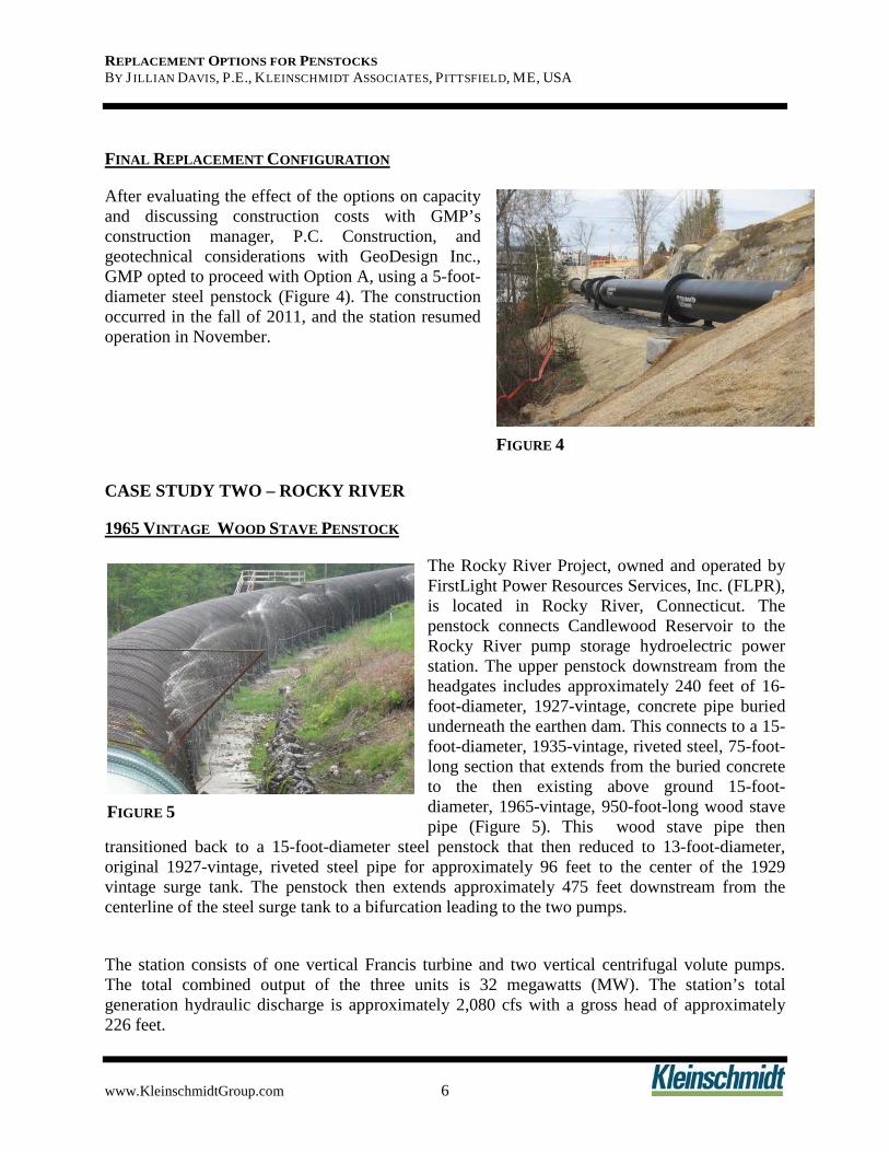
After evaluating the effect of the options on capacity and discussing construction costs with GMP’s construction manager, P.C. Construction, and geotechnical considerations with GeoDesign Inc., GMP opted to proceed with Option A, using a 5-foot-diameter steel penstock (
FINAL REPLACEMENT CONFIGURATION
Figure 4). The construction occurred in the fall of 2011, and the station resumed operation in November.
CASE STUDY TWO – ROCKY RIVER
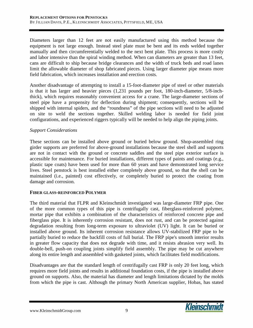
The Rocky River Project, owned and operated by FirstLight Power Resources Services, Inc. (FLPR), is located in Rocky River, Connecticut. The penstock connects Candlewood Reservoir to the Rocky River pump storage hydroelectric power station. The upper penstock downstream from the headgates includes approximately 240 feet of 16-foot-diameter, 1927-vintage, concrete pipe buried underneath the earthen dam. This connects to a 15-foot-diameter, 1935-vintage, riveted steel, 75-foot-long section that extends from the buried concrete to the then existing above ground 15-foot-diameter, 1965-vintage, 950-foot-long wood stave pipe (
1965 VINTAGE WOOD STAVE PENSTOCK
Figure 5). This wood stave pipe then transitioned back to a 15-foot-diameter steel penstock that then reduced to 13-foot-diameter, original 1927-vintage, riveted steel pipe for approximately 96 feet to the center of the 1929 vintage surge tank. The penstock then extends approximately 475 feet downstream from the centerline of the steel surge tank to a bifurcation leading to the two pumps.
The station consists of one vertical Francis turbine and two vertical centrifugal volute pumps. The total combined output of the three units is 32 megawatts (MW). The station’s total generation hydraulic discharge is approximately 2,080 cfs with a gross head of approximately 226 feet.
FIGURE 5
FIGURE 4
REPLACEMENT OPTIONS FOR PENSTOCKS BY J ILLIAN DAVIS, P.E., KLEINSCHMIDT ASSOCIATES, PITTSFIELD, ME, USA
www.KleinschmidtGroup.com 7
The wood stave portion of the penstock was last replaced in 1965, and by 2010, FLPR was concerned about its remaining reliable service life. The wood pipe consisted of 4-inch-thick staves banded by 1-inch-diameter steel hoops. The hoops originally were installed at approximately 6-inch centers, but because of leakage resulting in accelerated corrosion intermediate additional bands were installed in 2004, 2005, and 2008between the original 1965 bands for the entire length of pipe.
CONCERNS ABOUT THE WOOD STAVE PENSTOCK
As shown in Figure 5, the wood stave penstock leaked considerably. Where possible, normal techniques for repairing wooden pipe, such as wedges and plugs, had been used to minimize leakage and increase the service life of the penstock. During the 2010 dewatering, FLPR personnel attempted to reduce leakage further by placing rubber gasket material (Figure 6) between the steel bands and wooden staves, but this repair was time consuming. During the week outage, FLPR’s crew was able to insert only
approximately 30 feet of material along one side of the 940-foot-long wood stave pipe.
The leakage caused ancillary problems, such as corrosion of even the newer, recently installed bands; decay of exterior staves; and deterioration of the foundation. The wood staves had deteriorated to the degree that normal maintenance practices, such as chinking and plugs, were only minimally effective, and FLPR’s renewed attempt to limit leakage by inserting sheets of rubber between the staves and bands was too labor intensive and costly to provide any significant improvement. FLPR considered installing sheets of plywood to the pipe’s interior surfaces to control leakage, but this approach was also labor intensive, and the estimated effective service life of this repair option was less than 10 years.
Based on the extent of the leakage, FLPR decided that replacing the wood stave penstock was the most cost effective approach for maintaining the station’s reliable long-term operation.
Kleinschmidt evaluated various materials, diameters, alignments, methods of support, service lives, and costs for replacing the 950 feet of stave penstock. Concerns such as corrosion resistance, thermal reaction, and hydraulic characteristics, were evaluated for each penstock material, which included wood stave, steel and FRP.
METHOD FOR SELECTING REPLACEMENT MATERIAL AND CONFIGURATION
FIGURE 6
REPLACEMENT OPTIONS FOR PENSTOCKS BY J ILLIAN DAVIS, P.E., KLEINSCHMIDT ASSOCIATES, PITTSFIELD, ME, USA
www.KleinschmidtGroup.com 8
WOOD STAVE
MATERIAL COMPARISON
FLPR and Kleinschmidt investigated replacing the existing wood stave pipe in kind. The plan was to reuse the existing steel cradles that generally appeared in to be reasonable condition upon individual inspection during demolition of the existing penstock. The steel bands also would be reused as possible. FLPR had received shipment of the bands from Canbar Inc. (Canbar) between 2005 and 2008 as part of maintenance to tighten the staves and reduce leakage.
The nominally 4-foot by 6-inch staves would be machined to form a 15-foot ID pipe. Staves are typically kiln dried and then milled to concentric circles on the inside and outside faces and to the radial lines of the pipe on the edges. Edges are tongue-and-groove and milled to form a water tight seam. The staves are cut square on the ends and milled for spline or Kelsey Butt end joint connectors. Historically, staves were treated with creosote or chromate copper arsenate (CCA) to enhance the longevity of the penstock; however, these treatments are environmentally unacceptable and currently are not available as wood preservatives.
One of the advantages of wood stave penstocks is that they can be built using local labor under the direction of an experienced advisor that can be provided by the pipe supplier. . Although stave penstocks can be erected by a less skilled, less expensive labor force without heavy machinery, field installation is labor intensive, typically taking 8 to10 man-hours for each foot of pipe. At Rocky River where the site is readily accessible to heavy construction equipment, field installation of a wood stave penstock resulted in a total cost equal to or greater than that of installing pipes of other materials.
A wood stave penstock should be installed above ground on saddle supports. This keeps moisture from being retained in the stave exteriors, which would accelerate decay, and allows for inspection and maintenance to preserve the structural integrity of the penstock supports. The existing steel saddles would be reused where possible, reducing the cost of material and installation to replace the wood stave penstock.
STEEL
Diameter Selection Considerations FLPR and Kleinschmidt also investigated replacing the wood stave pipe with welded steel pipe in diameters ranging from 10 to 15 feet. Typically, steel penstock is shop fabricated into completed “cans” and then shipped to the site for installation and assembly at circumferential field joints. For typical thicknesses the cans are most efficiently fabricated as spiral welded pipe by twisting a steel sheet continuously over a mandrel and automatically welding the resulting helical spiral joint. If the pipe diameter is within a conveniently shippable size (i.e., less than 13 feet in diameter), then steel pipe can be shop fabricated into complete sections of 40 to 50 feet long, which minimizes field erection costs.
REPLACEMENT OPTIONS FOR PENSTOCKS BY J ILLIAN DAVIS, P.E., KLEINSCHMIDT ASSOCIATES, PITTSFIELD, ME, USA
www.KleinschmidtGroup.com 9
Diameters larger than 12 feet are not easily manufactured using this method because the equipment is not large enough. Instead steel plate must be bent and its ends welded together manually and then circumferentially welded to the next bent plate. This process is more costly and labor intensive than the spiral winding method. When can diameters are greater than 13 feet, cans are difficult to ship because bridge clearances and the width of truck beds and road lanes limit the allowable diameter of shop fabricated pieces. Using larger diameter pipe means more field fabrication, which increases installation and erection costs.
Another disadvantage of attempting to install a 15-foot-diameter pipe of steel or other materials is that it has larger and heavier pieces (1,231 pounds per foot, 180-inch-diameter, 5/8-inch-thick), which requires reasonably convenient access for a crane. The large-diameter sections of steel pipe have a propensity for deflection during shipment; consequently, sections will be shipped with internal spiders, and the “roundness” of the pipe sections will need to be adjusted on site to weld the sections together. Skilled welding labor is needed for field joint configurations, and experienced riggers typically will be needed to help align the piping joints.
Support Considerations These sections can be installed above ground or buried below ground. Shop-assembled ring girder supports are preferred for above-ground installations because the steel shell and supports are not in contact with the ground or concrete saddles and the steel pipe exterior surface is accessible for maintenance. For buried installations, different types of paints and coatings (e.g., plastic tape coats) have been used for more than 60 years and have demonstrated long service lives. Steel penstock is best installed either completely above ground, so that the shell can be maintained (i.e., painted) cost effectively, or completely buried to protect the coating from damage and corrosion.
FIBER GLASS-REINFORCED POLYMER
The third material that FLPR and Kleinschmidt investigated was large-diameter FRP pipe. One of the more common types of this pipe is centrifugally cast, fiberglass-reinforced polymer, mortar pipe that exhibits a combination of the characteristics of reinforced concrete pipe and fiberglass pipe. It is inherently corrosion resistant, does not rust, and can be protected against degradation resulting from long-term exposure to ultraviolet (UV) light. It can be buried or installed above ground. Its inherent corrosion resistance allows UV-stabilized FRP pipe to be partially buried to reduce the backfill costs of full burial. The FRP pipe's smooth interior results in greater flow capacity that does not degrade with time, and it resists abrasion very well. Its double-bell, push-on coupling joints simplify field assembly. The pipe may be cut anywhere along its entire length and assembled with gasketed joints, which facilitates field modifications.
Disadvantages are that the standard length of centrifugally cast FRP is only 20 feet long, which requires more field joints and results in additional foundation costs, if the pipe is installed above ground on supports. Also, the material has diameter and length limitations dictated by the molds from which the pipe is cast. Although the primary North American supplier, Hobas, has stated
REPLACEMENT OPTIONS FOR PENSTOCKS BY J ILLIAN DAVIS, P.E., KLEINSCHMIDT ASSOCIATES, PITTSFIELD, ME, USA
www.KleinschmidtGroup.com 10
that larger diameters may be available in the future, but in 2012 the largest available pipe diameter was 10 feet, 6 inches.
BURIED PENSTOCK VS. EXPOSED PENSTOCK
Another design consideration included whether to install the replacement penstock above or below grade. Table 2 summarizes some of the advantages and disadvantages of buried and exposed penstocks.
TABLE 2 SUMMARY OF ADVANTAGES AND DISADVANTAGES OF BURIED AND EXPOSED PENSTOCKS
ADVANTAGES DISADVANTAGES Buried Penstocks
• Soil cover protects the penstocks from temperature variation and eliminates the need for expansion joints.
• Temperature consistency allows rust and turbicles to remain tightly adhered to the internal surface of steel pipes, thereby helping to prevent progressive thinning and pitting of the pipe wall.
• Soil cover protects the conveyed water from freezing.
• Concealment offers increased protection against physical damage by vandals, animals, or earthquakes.
• The continuity of support offers structural redundancy and reduces the potential for support problems or failure.
• Exterior surfaces are not accessible for inspection.
• Exterior steel surfaces may require special coating to protect them from the corrosive action of salts in the soil, especially near road crossings where deicing salts are applied in winter.
Exposed Penstocks
• The entire shell exterior can be inspected and repaired readily. This is especially important for steel or wood.
• The penstock is exposed to large temperature variations and may require expansion joints and sliding supports.
• For FRP, the field joints are not able to transmit shear and movement. Therefore, each section of FRP pipe needs to be supported on each end, resulting in a large number of saddles and field foundations.
Kleinschmidt recommended that if FLPR selected steel or wood to replace the penstock, it should be installed above ground on saddles or supports to allow for inspection and maintenance to preserve the structural integrity of the penstock shell. The recommended approach for FRP pipe was continuous ground support to reduce the number of required field foundations. If properly UV protected, the pipe would only require burying to the spring line.
REPLACEMENT OPTIONS FOR PENSTOCKS BY J ILLIAN DAVIS, P.E., KLEINSCHMIDT ASSOCIATES, PITTSFIELD, ME, USA
www.KleinschmidtGroup.com 11
HYDRAULIC COMPARISON
For a preliminary hydraulic comparison of materials in 2010, the replacement pipe followed the original alignment, regardless of material; therefore, all line losses were based on the same length of pipe, and the effect on velocities depended upon the friction factor of the various materials. The total gross head loss through the penstock is a combination of the losses through the section of penstock being replaced and the existing concrete and steel sections to remain. In all cases, the optimum penstock flow for this pump storage station was determined by both the upper pumping capacity and the maximum generation. During the initial replacement study, the optimum penstock flow was defined as 2,080 cfs, which is the total combined hydraulic capacity of all the units. When comparing pipes of equal diameters, the head loss (resistance to flow) was less with the centrifugally cast FRP pipe, followed by the steel pipe (Table 3). The uneven interior surface of the stave pipe created the most significant head loss of the three materials considered.
TABLE 3 MATERIAL VS HEADLOSS
MATERIAL HEADLOSS Wood Stave 1.97 ft Steel Pipe 1.86 ft
FRP 1.11 ft In 2011, FLPR requested a review of optimal penstock diameter in response to the station’s limited capacity factor and the unlikely future expansion of the electrical generation capacity, and to match the diameter of the new penstock with demand more effectively. The upper penstock is 15 feet in diameter and appeared to have been sized to accommodate potential future expansion of the Rocky River Power Station based on the partial construction of a downstream bifurcation in 1929. Just prior to the surge tank, the penstock diameter reduces to 13 feet. As the penstock reaches the power house, the flow is split between the two pumping units and the main turbine. At this location, the diameter of the penstock to the main turbine reduces to 11 feet.
For a follow-up evaluation of alternatives, FLPR specified that the penstock was to be sized to support generation using the main turbine only. Flow rates to the turbine of 1,370 cfs and 1,470 cfs were evaluated because these rates were defined as the points of best turbine efficiency and best gate, respectively. Kleinschmidt examined total head loss for the penstock and overall performance when the stave section of penstock was replaced with FRP pipe that ranged from 13 feet in diameter to 7 feet in diameter. Most of the flow analysis was based on friction factors (flow resistance) associated with fiberglass/plastic pipe. The upper diameter of 13 feet was selected because this is the same size as the lower penstock, and it is the upper limit for shipping.
REPLACEMENT OPTIONS FOR PENSTOCKS BY J ILLIAN DAVIS, P.E., KLEINSCHMIDT ASSOCIATES, PITTSFIELD, ME, USA
www.KleinschmidtGroup.com 12
COST COMPARISON
Kleinschmidt and FLPR eliminated steel and stave penstock materials because they are initially costlier, require more maintenance long term, and especially in the case of stave, have a shorter estimated service life (Table 4). Then, FLPR and Kleinschmidt compared how FRP pipe of various diameters affected resulting annual plant output.
TABLE 4 ESTIMATED COSTS AND SERVICE LIFE
MATERIAL ESTIMATED MATERIAL COST
ESTIMATED TOTAL
INSTALLED COST
ESTIMATED SERVICE LIFE
Wood Stave (15 ft. Φ) $1,200,000 $2,750,000 < 45 years Steel Pipe (15 ft. Φ) $2,100,000 $3,500,000 50-80 years FRP (10 ft. Φ) $900,000 $2,100,000 80+ years
Average annual plant electrical output from 2000 to 2009 was used to compute the potential annual revenue and to establish the electrical generation capacity factor (6.9 percent). By maintaining a constant capacity factor, decreasing the size of the replacement penstock increased head loss between the dam and the turbine, and this translated to a loss of generation within a constrained period of time. Using the 13-foot-diameter penstock as the basis for the replacement penstock, each 1-foot decrease in the diameter of the replacement penstock resulted in an increase of lost annual revenues. Cost estimates for replacement penstocks of the various diameters were used to compare total project cost to anticipated “loss” of generation for each size of pipe. Using replacement penstock with a diameter of less than 10 feet, revenue losses due to increased head loss would increase more dramatically than the reduction in the cost of the replacement pipe. That is, the decrease in electrical generation for a penstock of smaller diameter greatly exceeded the cost savings associated with using the smaller pipe.
As a result of this review, FLPR selected the centrifugally cast, FRP pipe based on price, corrosion resistance, minimum future maintenance and minimum head loss at full flow. The selection of the 10-foot-diameter replacement penstock was based on minimizing the initial replacement cost of the penstock without significantly reducing the present and foreseeable electrical output of the main turbine generator. The replacement penstock included a provision for the later addition of a second parallel penstock if future conditions result in a higher station capacity factor that would warrant lowering the head losses at higher station discharges. The Rocky River penstock replacement project went out to bid for pipe supply in January 2012, installation bids in March
FINAL REPLACEMENT CONFIGURATION
FIGURE 7
REPLACEMENT OPTIONS FOR PENSTOCKS BY J ILLIAN DAVIS, P.E., KLEINSCHMIDT ASSOCIATES, PITTSFIELD, ME, USA
www.KleinschmidtGroup.com 13
and was completed by December 2012. Figure 7 shows the upstream portion of the completed section of replacement FRP pipe.
CASE STUDY THREE – ORONO
The Orono Hydroelectric Project, previously owned and operated by Bangor Hydroelectric Co., is located on the Penobscot River in Orono, Maine. In 1996 the penstock intake structure was located on the right side (looking downstream) of a 1,067-foot-long concrete dam. Three, 10-foot-diameter, 1960-vintage wood stave penstocks ran approximately 860 linear feet from the intake beneath a railroad trestle until they transitioned to 10-foot-diameter penstocks averaging 50 feet long leading to four units totaling 2.33 MW. A fourth, 12-foot-diameter stave penstock had been decommissioned in 1953. The net head at the site is approximately 29.4 feet.
ORIGINAL PENSTOCK LAYOUT
The Orono Project has not operated since June 1, 1996, when the two remaining penstocks failed. The first penstock collapsed in 1994. The repair or replacement of the penstocks was deemed unnecessary because the project was scheduled for decommissioning as part of the Basin Mills development. All three penstocks were disabled, and the Orono Plant was shut down. In 1998 the Federal Energy Regulatory Commission (FERC) denied the Basin Mills development. In 1999 FERC approved transfer of the license from Bangor Hydro to PPL Maine, LLC, which became Black Bear Hydro in 2009 and was acquired by Brookfield in 2014.
WOOD STAVE PENSTOCK FAILURE
In 2001 PPL Maine began planning the repowering of the Orono Hydroelectric Station and enlisted Kleinschmidt to provide engineering services. Preliminary plans were to replace the three penstocks with 1/2-inch thick, 10-foot-diameter, steel penstocks supported either by ring girders or saddles. Although the penstocks could span further on ring girders, thus requiring less support, Kleinschmidt’s preliminary analysis indicated that supporting the penstocks on saddles spaced at 25 feet on center would be the less costly of the two options. At the time of the penstock replacement, however, the expense of fabricating and shipping three, 10-foot-diameter steel penstocks was high, so Kleinschmidt suggested that PPL Maine investigate the use of cast-
METHOD FOR SELECTING REPLACEMENT MATERIAL AND CONFIGURATION
FIGURE 8
REPLACEMENT OPTIONS FOR PENSTOCKS BY J ILLIAN DAVIS, P.E., KLEINSCHMIDT ASSOCIATES, PITTSFIELD, ME, USA
www.KleinschmidtGroup.com 14
in-place concrete. After investigating the costs, PPL Maine agreed, and Kleinschmidt proceeded to design a concrete penstock.
In 2008 Kleinschmidt began designing a rectangular concrete penstock, or a four-sided concrete flume, to transport water from the intake to the powerhouse. At the intake, the penstock was connected at the location of the three, 10-foot-diameter stubs left by the previous penstocks. Approximately 200 feet downstream of the intake is a railroad trestle that has 13.2 feet of clearance between the underside beams and bedrock. To pass enough flow and travel beneath the bridge, the penstock has interior dimensions of 20 feet wide by 10 feet tall upstream and below the bridge and then transitions to 12 feet tall downstream of the bridge. The 10-foot height combined with a base slab and roof capable of spanning the 20-foot width allows for a 9-inch clearance below the bridge beams. Approaching the powerhouse, the penstock transitions to an open flume rather than using a surge tank.
The design of the concrete penstock accounted for head loss obstructions and transition from one cross section to another. Its area was calculated to match the total combined area of the three, 10-foot-diameter penstocks (except under the bridge where the height was reduced to fit between the existing railroad steel and the bedrock).Unlike the original arrangement, the new penstock did not suddenly expand into the surge chamber. Rather the concrete, box-shaped penstock reduced headloss by flaring the intersection with the surge chamber without sudden enlargements, and the floor of the surge chamber was filled with concrete and sloped up to the gate sills to provide a smooth transition to the gates. Between the hydraulic considerations and rebuilding the three units, PPL Maine was able to increase its generation from 2.33 MW to 2.78 MW.
Kleinschmidt also evaluated the merits of using a three-sided flume and sealing the base with flowable fill. Some of the considerations for this evaluation were the cost of flowable fill versus reinforced concrete, the total quantity of each required, the affect on the reinforcement, the requirements to dowel to bedrock to accommodate the design loads, the ease of construction access, and formwork provisions. PPL Maine's decision on which option to use was based on the 5- to 10-year payback period.
Operations at the Orono Powerhouse recommenced in January 2009.
FINAL REPLACEMENT CONFIGURATION
REPLACEMENT OPTIONS FOR PENSTOCKS BY J ILLIAN DAVIS, P.E., KLEINSCHMIDT ASSOCIATES, PITTSFIELD, ME, USA
www.KleinschmidtGroup.com 15
FIGURE 9
BIOGRAPHICAL SKETCH
Jillian Davis, P.E. Ms. Davis joined Kleinschmidt Associates in January 2008 as a civil/structural engineer and is a Project Engineer in the Hydro Resources Engineering Department. Ms. Davis earned her B.S. in Civil Engineering from the University of Maine, Orono. Ms. Davis has participated in many projects including the design of new hydroelectric structures, the rehabilitation of existing hydroelectric sites, and the inspection of penstocks and water retaining structures.