146
BYOD—Identity and Authentication SOLUTION DESIGN GUIDE August 2013

BYOD—Identity and AuthenticationSOlutIOn DESIgn guIDE
August 2013

table of Contents
Table of Contents
Preface ........................................................................................................................................1
CVD Navigator .............................................................................................................................2use Cases .................................................................................................................................. 2Scope ......................................................................................................................................... 2Proficiency .................................................................................................................................. 2
Introduction .................................................................................................................................3technology use Cases ............................................................................................................... 3
use Case: Allowing Only Employees Access to the network ................................................. 4use Case: Controlling the Services a user Can Access Based on group Membership .......... 4
Design Overview ......................................................................................................................... 4
Deployment Details ......................................................................................................................6Enable Authentication ................................................................................................................. 6
Deploying Cisco Identity Services Engine ............................................................................... 6Enabling Visibility to the lAn ................................................................................................ 18Enabling Visibility to the Wireless network ........................................................................... 34Deploying Digital Certificates ................................................................................................ 39Enabling 802.1X Authentication ............................................................................................. 48Configuring group Policy Objects ......................................................................................... 56Deploying Cisco AnyConnect on Windows Endpoints .......................................................... 72Configuring Mac Workstations for 802.1X Authentication ...................................................... 77Configure Mac OS X Supplicant ........................................................................................... 80
Enable Authorization ................................................................................................................. 80Enabling Authorization for Cisco IP Phones .......................................................................... 80Enabling Authorization for Wireless Access Points ............................................................... 81Modifying the MAB Authentication Policy ............................................................................. 84Enabling Authorization for Wired Endpoints .......................................................................... 85Enabling Authorization for Wireless Endpoints ...................................................................... 97Modifying the Authorization Policy to be Closed ................................................................. 100Enabling EAP Chaining ....................................................................................................... 102Enabling Downloadable Access lists ................................................................................... 111Enabling Security group Access .........................................................................................116Monitoring network Access ............................................................................................... 130
Appendix A: Product List ......................................................................................................... 141

Preface August 20131
PrefaceCisco Validated Designs (CVDs) provide the framework for systems design based on common use cases or current engineering system priorities. they incorporate a broad set of technologies, features, and applications to address customer needs. Cisco engineers have comprehensively tested and documented each CVD in order to ensure faster, more reliable, and fully predictable deployment.
CVDs include two guide types that provide tested and validated design and deployment details:
• Technology design guides provide deployment details, information about validated products andsoftware, and best practices for specific types of technology.
• Solution design guides integrate or reference existing CVDs, but also include product features andfunctionality across Cisco products and may include information about third-party integration.
Both CVD types provide a tested starting point for Cisco partners or customers to begin designing and deploying systems using their own setup and configuration.
How to Read CommandsMany CVD guides tell you how to use a command-line interface (ClI) to configure network devices. this section describes the conventions used to specify commands that you must enter.
Commands to enter at a ClI appear as follows:
configure terminal
Commands that specify a value for a variable appear as follows:
ntp server 10.10.48.17
Commands with variables that you must define appear as follows:
class-map [highest class name]
Commands at a ClI or script prompt appear as follows:
Router# enable
long commands that line wrap are underlined. Enter them as one command:
police rate 10000 pps burst 10000 packets conform-action set-discard-class-transmit 48 exceed-action transmit
noteworthy parts of system output or device configuration files appear highlighted, as follows:
interface Vlan64
ip address 10.5.204.5 255.255.255.0
Comments and QuestionsIf you would like to comment on a guide or ask questions, please use the feedback form.
For the most recent CVD guides, see the following site:
http://www.cisco.com/go/cvd

CVD navigator August 20132
CVD navigatorthe CVD navigator helps you determine the applicability of this guide by summarizing its key elements: the use cases, the scope or breadth of the technology covered, the proficiency or experience recommended, and CVDs related to this guide. this section is a quick reference only. For more details, see the Introduction.
Use Casesthis guide addresses the following technology use cases:
• Allowing Only Employees Access to the Network—A customer wants to require all devices accessing the network to be authenticated before being allowed access.
• Controlling the Services a User Can Access Based on Group Membership—A customer wants to correlate network access policies with business groups.
For more information, see the “use Cases” section in this guide.
Scopethis guide covers the following areas of technology and products:
• lAn access layer switching
• Onsite and remote-site wireless lAn controllers
• Data center firewalls
• Management and user authentication, authorization, and policy
For more information, see the “Design Overview” section in this guide.
Proficiencythis guide is for people with the following technical proficiencies—or equivalent experience:
• CCNP Routing and Switching—3 to 5 years planning, implementing, verifying, and troubleshooting local and wide-area networks
• CCNP Security—3 to 5 years testing, deploying, configuring, maintaining security appliances and other devices that establish the security posture of the network
• CCNP Wireless—3 to 5 years designing, installing, and troubleshooting wireless lAns
Related CVD Guides
Campus Wired LANTechnology Design GuideVALIDATED
DESIGN
Campus Wireless LANTechnology Design GuideVALIDATED
DESIGN
to view the related CVD guides, click the titles or visit the following site:
http://www.cisco.com/go/cvd

Introduction August 20133
Introductionthere is a trend in the marketplace today that is often referred to as Bring Your Own Device (BYOD). BYOD is a spectrum of business problems that can be solved in various ways. these range from accessing guest wireless networks to providing device authentication and identification. the goal is to provide a common work environment, regardless of the type of device being used. this could be accomplished by providing a virtualized desktop or by allowing users to self-register devices for use on the network.
Organizations are experiencing an unprecedented transformation in the network landscape. In the past, It typically provided network resources only to corporate-managed PCs, such as laptops and desktops. today, employees are requiring access from both corporate managed and unmanaged devices, including mobile devices like smart phones and tablets. this rapid proliferation of mobile devices capable of supporting applications drastically increases workforce mobility and productivity, but it also presents an enormous challenge to It organizations seeking to enforce security policies across a growing population of devices, operating systems, and connectivity profiles.
the distinction between a work device and a personal device has evolved. this evolution of mobile device usage and the introduction of mobile devices into the workplace has caused a paradigm shift in how It views what qualifies as a network “end point device” and also what it means to “be at work.”
An organization needs to know not only who is accessing their wired and wireless networks, but also when the networks are accessed and from where. In addition, with the wide adoption of nontraditional devices, such as smart phones and tablets, and people bringing their own devices to access the network, organizations need to know how many of these devices are connecting. With this information, the organization can create policy to prevent connection by nontraditional devices, limit connection to approved devices, or make access to network resources easier for these non-traditional devices. this presents a challenge for It organizations that seek to provide end-users with a consistent network access experience and the freedom to use any device, while still enforcing stringent security policies to protect corporate intellectual property. Further complicating the situation is delivering both consistent access and enforcing proper security policy based on the specific user-access scenario (wired, wireless, guest, local, branch, and remote users).
to balance the productivity gains versus the security risks, It needs to implement a solution that allows for seamless on-boarding of users and devices, simplicity of on-going operations, and the ability to extend end-user applications to any user or any device at any time.
Technology Use CasesWith an increasingly mobile workforce and a diverse number of platforms used to gain access to the network, organizations are looking for ways to monitor and control network access. An organization needs to know not only who is accessing their wired and wireless networks, but also when the networks were accessed and from where. In addition, with the wide adoption of devices such as smart phones and tablets and with people bringing their own devices to access the network, organizations need to know how many of these devices are connecting. With this information, the organization can create a policy to prevent connection by nontraditional devices, limit connection to approved devices, or make access to network resources easier for these nontraditional devices.
Organizations are being driven by industry and regulatory compliance (PCI, Sarbanes-Oxley) to be able to report on who is accessing the organization’s information, where they are accessing it from, and what type of device they are using to access it. government mandates such as Federal Information Processing Standard (FIPS) and Federal Information Security Management Act (FISMA) are also requiring agencies and entities working with government agencies to track this information. In some cases, an organization may choose to limit access to certain information in order to adhere to these regulations.

Introduction August 20134
this information is also key data that can be used to generate advanced security policies. Organizations see this as a daunting task requiring the use of several advanced technologies and often delay implementing a solution simply because they don’t know where to begin.
this guide is the first step in deploying a complete identity-based architecture. Future projects will address additional use cases that will focus on the features that will provide for things such as enforcement, guest access, and confidentiality.
Use Case: Allowing Only Employees Access to the NetworkA customer wants to require all devices accessing the network to be authenticated before being allowed access.
this design guide enables the following network capabilities:
• Identify the types of devices accessing the network
• Authenticate by using 802.1X authentication on the wired and wireless networks for both users and devices
• Monitor the users and devices that are accessing the network, and when they are accessing the network
Use Case: Controlling the Services a User Can Access Based on Group MembershipA customer wants to correlate network access policies with business groups. However, employees can use one of several mobile devices to log in to the wireless network. Additionally, device IP addresses can change as employees move throughout the campus to attend meetings during the day.
this design guide enables the following network capabilities:
• Identify the types of devices accessing the network
• limit access to the network using access lists and Security group tag Access lists (SgACls), based on the group to which the employee belongs
Design OverviewCisco Identity Services Engine (ISE) is an identity and access control policy platform that enables organizations to enforce compliance, enhance infrastructure security, and streamline their service operations. Cisco ISE is a core component of Cisco trustSec. Its architecture allows an organization to gather real-time contextual information from the network, users, and devices to make proactive policy decisions by tying identity into network elements such as access switches, wireless controllers, and VPn gateways.
this deployment uses Cisco ISE as the authentication, authorization, and accounting server for the wired and wireless networks using RADIuS. Cisco ISE acts as a proxy to the existing Active Directory (AD) services to maintain a centralized identity store for all network services.
In addition to authentication, this deployment uses Cisco ISE to profile devices in order to determine the specific type of devices that are accessing the network. this is done by examining network traffic for certain criteria, based on certain characteristics. Cisco ISE currently has probes for Dynamic Host Configuration Protocol (DHCP), HttP, RADIuS, Domain name System (DnS), Simple name Management Protocol (SnMP) traps and queries, network Mapper (nmap) scans, and Cisco IOS netFlow. to analyze the traffic, the engine can be deployed as an inline policy enforcement device, or the traffic can be forwarded to the engine. As an example, the network infrastructure is configured to send DHCP and Cisco Discovery Protocol (CDP) data via RADIuS to Cisco ISE for analysis. the engine then evaluates the RADIuS data and can identify the device based off of the data in the RADIuS packet. For example, Cisco IP Phones are identified by their DHCP class identifier.

Introduction August 20135
In the lAn, there are three modes for deploying Cisco trustSec: monitor mode, low-impact mode, and closed mode. Cisco recommends a phased deployment model that can allow for limited impact on network access while gradually introducing authentication/authorization on the network. An organization’s goals might be met by implementing only some of the overall functionality of Cisco trustSec and a successful deployment does not require all three modes to be deployed. this document covers the deployment phases of monitor mode and low-impact mode both at the headquarters site and the remote sites, with Cisco ISE being centralized in the data center. the deployment in use deploys two features within Cisco IOS on the switches in the access layer at both the headquarters sites as well as the remote sites. the first is MAC Authentication Bypass (MAB), which authenticates the device on the switch port by the MAC address. Monitor mode logs the MAC addresses that connect and grant access to any device that connects. the second feature is 802.1X open mode, which allows the switch port to give unrestricted access to the network even though authentication and authorization have not been performed. this enables the deployment of identity without affecting existing connectivity. this phased approach allows you to prepare for moving to another mode in the future. In addition to these features, this deployment also deploys the Security group Access (SgA) features of Security group tags (Sgt) and Security group Exchange Protocol (SXP) in low-impact mode in order to enforce the access policy. Packets for a particular group are marked with an Sgt in the trustSec header. SXP is used to pass tagged packets across devices that do not support marking Sgts by binding the IP address of the device to the Sgt and then passing the packets along to a device that does support Sgts. Devices then enforce a security policy using these tags. In the organization, these switch configurations will be managed by Cisco Prime lAn Management Solution (lMS) 4.2 and the new trustSec Work Center. Cisco Prime lMS simplifies the deployment of identity by performing a network-readiness assessment for an identity deployment, providing templates for the various modes—monitor, low-impact, closed—and providing a step-by-step wizard to configure the various components required.
You accomplish integrating Cisco ISE into the wireless network by using Cisco ISE as the RADIuS server for wireless 802.1X authentication, authorization, and accounting. You configure this on every wireless lAn controller (WlC) in the network, at both headquarters and the remote sites. the one exception is for the controller used for guest access. You can also configure the WlCs to forward DHCP requests to Cisco ISE in order to enable the profiling of wireless endpoints.
Figure 1 - Cisco ISE integration into CVD
Cisco ISE
ActiveDirectory
WirelessLAN Controller
10
28
RADIUS
Internet Edge
Remote Access VPN
CertificateAuthority
Core
Distribution
Access
Data Center
Remote Site
LDAPDHCP

Deployment Details August 20136
Deployment Detailsthe deployment described here bases all IP addressing off of the Campus Wired lAn Design guide. Any IP addresses used in this guide are examples; you should use addressing that is applicable to your architecture.
Cisco ISE has different personas, or modes, for which it can be configured: administration, policy service, and monitoring. For a standalone configuration where the appliance is all personas, the maximum number of endpoints that can be supported is 2000. to support a greater number of endpoints, you will need to divide the personas across multiple appliances. In this example, there is a primary and secondary policy service and administration node and a primary and secondary monitoring node. this will allow the deployment to scale to 10,000 endpoints. If your deployment does not require support for more than 2000 endpoints, then you can just have a primary and secondary set of engines that support all the personas.
Table 1 - Cisco ISE engine IP addresses and hostnames
Device IP address Hostname
Primary Cisco ISE administration and policy service node 10.4.48.41 ise-1.cisco.local
Secondary Cisco ISE administration and policy service node 10.4.48.42 ise-2.cisco.local
Primary Cisco ISE monitoring node 10.4.48.43 ise-3.cisco.local
Secondary Cisco ISE monitoring node 10.4.48.44 ise-4.cisco.local
Enable Authentication
Deploying Cisco Identity Services Engine
1. Set up initial primary engine
2. Set up the remaining engines
3. Configure certificate trust list
4. Configure Cisco ISE deployment nodes
5. Install Cisco ISE license
6. Configure network devices in Cisco ISE
7. Configure Cisco ISE to use Active Directory
8. Disable IP Phone authorization policy
PR
OC
ESS
Deployment Details August 20137
Procedure 1 Set up initial primary engine
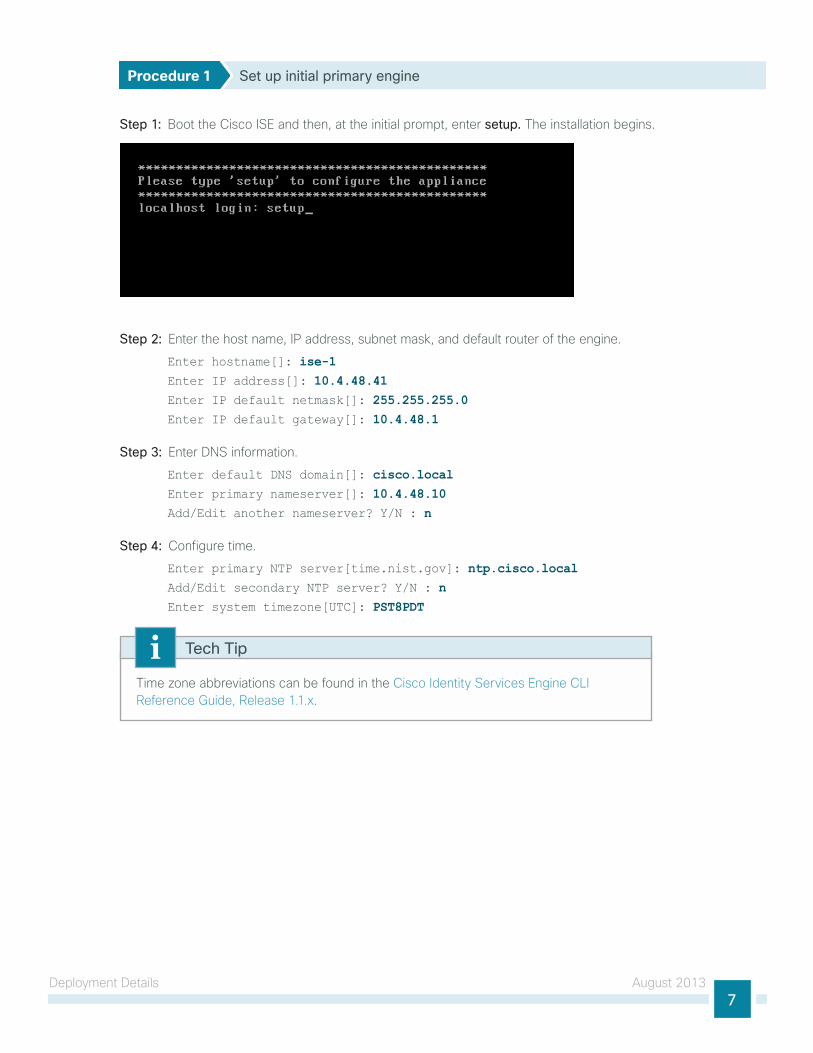
Step 1: Boot the Cisco ISE and then, at the initial prompt, enter setup. the installation begins.
Step 2: Enter the host name, IP address, subnet mask, and default router of the engine.
Enter hostname[]: ise-1Enter IP address[]: 10.4.48.41Enter IP default netmask[]: 255.255.255.0Enter IP default gateway[]: 10.4.48.1
Step 3: Enter DnS information.
Enter default DNS domain[]: cisco.localEnter primary nameserver[]: 10.4.48.10Add/Edit another nameserver? Y/N : n
Step 4: Configure time.
Enter primary NTP server[time.nist.gov]: ntp.cisco.localAdd/Edit secondary NTP server? Y/N : nEnter system timezone[UTC]: PST8PDT
time zone abbreviations can be found in the Cisco Identity Services Engine ClI Reference guide, Release 1.1.x.
Tech Tip

Deployment Details August 20138
Step 5: Configure an administrator account.
You must configure an administrator account in order to access to the ClI console. this account is not the same as the one used to access the guI.
Enter username[admin]: adminEnter password: [password]Enter password again: [password]
Cisco ISE completes the installation and reboots. this process takes several minutes. You are asked to enter a new database administrator password and a new database user password during the provisioning of the internal database. Do not press Control-C during the installation, or the installation aborts.
the primary engine is now installed.
Procedure 2 Set up the remaining engines
the procedure for setting up the remaining engines is the same as the primary, with the only difference being the IP address and host name configured for the engine. to set up the remaining engines, follow Procedure 1, “Cisco ISE integration into CVD,” and use the values supplied in table 1 for the remaining engines.
Procedure 3 Configure certificate trust list
the engines use public key infrastructure (PKI) to secure communications between them. Initially in this deployment, you use local certificates, and you must configure a trust relationship between all of the engines. to do this, you need to import the local certificates from the secondary administration node and the two monitoring nodes into the primary administration node.
Step 1: In your browser, connect to the secondary engine’s guI at http://ise-2.cisco.local.
Step 2: In Administration > System, select Certificates.
Step 3: In the local Certificates window, select the local certificate by selecting the box next to the name of the secondary engine, ise-2.cisco.local, and then click Export.
Step 4: Choose Export Certificate Only, and then click Export.
Step 5: When the browser prompts you to save the file to a location on the local machine, choose where to store the file and make a note of it. You will be importing this file into the primary engine.
Step 6: In a browser, access the primary engine’s guI at http://ise-1.cisco.local.

Deployment Details August 20139
Step 7: In Administration > System, select Certificates.
Step 8: In the Certificate Operations pane on the left, click Certificate Store, and then click Import.
Step 9: next to the Certificate File box, click Browse, and then locate the certificate exported from the secondary engine. It has an extension of .pem. Click Submit.
Step 10: Repeat this procedure for the remaining engines, ise-3.cisco.local and ise-4.cisco.local.
Procedure 4 Configure Cisco ISE deployment nodes
You can configure the personas of Cisco ISE—administration, monitoring, and policy service—to run all on a single engine or to be distributed amongst several engines. For this example installation, you will deploy a pair of engines for administration and policy service with one serving as primary and the other secondary and another pair of engines for monitoring with one serving as primary and the other secondary.
Step 1: Connect to http://ise-1.cisco.local.
Step 2: From the Administration menu, choose System, and then choose Deployment. A message appears notifying you that the node is currently stand-alone. Click OK.
Step 3: In the Deployment pane, click the gear icon, and then select Create Node Group.
In order for the two Cisco ISE devices to share policy and state information, they must be in a node group. the nodes use IP multicast to distribute this information, so they need to be able to communicate via IP multicast.
Step 4: Configure the node group with the node group name ISE-Group and the default multicast address of 228.10.11.12, and then click Submit.
Step 5: A pop-up window lets you know the group was created successfully. Click OK.
Deployment Details August 201310
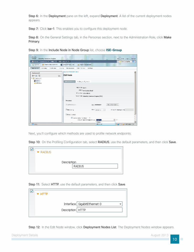
Step 6: In the Deployment pane on the left, expand Deployment. A list of the current deployment nodes appears.
Step 7: Click ise-1. this enables you to configure this deployment node.
Step 8: On the general Settings tab, in the Personas section, next to the Administration Role, click Make Primary.
Step 9: In the Include Node in Node Group list, choose ISE-Group.
next, you’ll configure which methods are used to profile network endpoints.
Step 10: On the Profiling Configuration tab, select RADIUS, use the default parameters, and then click Save.
Step 11: Select HTTP, use the default parameters, and then click Save.
Step 12: In the Edit node window, click Deployment Nodes List. the Deployment nodes window appears.

Deployment Details August 201311
Step 13: Click Register, and then choose Register an ISE Node.
Step 14: Enter the IP address or host name of the primary monitoring Cisco ISE engine from table 1 (in this example, ise-3.cisco.local) and the credentials for the admin account, and then click Next.
Step 15: Select Monitoring, and then in the Role list, choose Primary. Make sure Administration and Policy Service are not selected.
Step 16: Click Submit. the node registers, and a pop-up window displays letting you know that the process was successful. Click OK.
Step 17: In the Deployment node window, click ise-1.

Deployment Details August 201312
Step 18: Clear Monitoring, and then click Save. the node updates, and a message displays letting you know that the process was successful. Click OK. the node restarts.
Step 19: log in to the console, and then in the Administration menu, in the System section, choose Deployment.
Step 20: In the Deployment node window, click Register, and then choose Register an ISE Node.
Step 21: Enter the IP address or host name of the secondary administration Cisco ISE from table 1 (in this example, ise-2.cisco.local) and the credentials for the admin account, and then click Next.
Step 22: Select only Administration and Policy Service. In the Administration section, in the Role list, choose Secondary, and then in the Policy Service section, in the Node Group list, choose ISE-Group.
Step 23: Click Submit. the node registers, and a pop-up window displays letting you know that the process was successful. Click OK.

Deployment Details August 201313
next, you’ll configure which methods are used to profile network endpoints for the secondary policy service node.
Step 24: In the Deployment Nodes list, click ise-2.
Step 25: On the Profiling Configuration tab, select RADIUS, and use the default parameters.
Step 26: Select HTTP, use the default parameters, and then click Save.
Step 27: In the Edit node window, click Deployment Nodes List. the Deployment nodes window appears.
Step 28: In the Deployment nodes window, click Register, and then choose Register an ISE Node.
Step 29: Enter the IP address or host name of the secondary monitoring Cisco ISE from table 1 (in this example, ise-4.cisco.local) and the credentials for the admin account, and then click Next.
Step 30: Select Monitoring, and then in the Role list, choose Secondary. Make sure Administration and Policy Service are not selected.

Deployment Details August 201314
Step 31: Click Submit. the node registers, and a pop-up window displays letting you know that the process was successful. Click OK.
You have now deployed all Cisco ISE nodes: a pair of redundant administration and policy service nodes and a pair of redundant monitoring nodes.
Procedure 5 Install Cisco ISE license
Cisco ISE comes with a 90-day demo license for both the Base and Advanced packages. to go beyond 90 days, you need to obtain a license from Cisco. In a redundant configuration, you only need to install the license on the primary administration node.
When installing a Base license and an Advanced license, the Base license must be installed first.
Tech Tip
Step 1: Mouse over Administration, and then, from the System section of the menu, choose Licensing.
notice that you only see one node here since only the primary administration node requires licensing.
Step 2: Click the name of the Cisco ISE server. this enables you to edit the license details.
Step 3: under licensed Services, click Add Service.

Deployment Details August 201315
Step 4: Click Browse, locate your license file, and then click Import.
Step 5: If you have multiple licenses to install, repeat the process for each.
Procedure 6 Configure network devices in Cisco ISE
Configure Cisco ISE to accept authentication requests from network devices. RADIuS requires a shared secret key to enable encrypted communications. Each network device that will use Cisco ISE for authentication will need to have this key.
Step 1: Mouse over Administration, and then, from the network Resources section of the menu, choose Network Devices.
Step 2: In the left pane, click Default Device.
Each network device can be configured individually, or devices can be grouped by location, by device type, or by using IP address ranges. the other option is to use the Default Device to configure the parameters for devices that aren’t specifically configured. All network devices in this example use the same key, so for simplicity, this example uses the Default Device.
Tech Tip
Step 3: In the Default Network Device Status list, choose Enable.
Step 4: Enter the RADIuS shared secret, and then click Save.

Deployment Details August 201316
Procedure 7 Configure Cisco ISE to use Active Directory
Cisco ISE will use the existing Active Directory (AD) server as an external authentication server. First, you must configure the external authentication server.
Step 1: Mouse over Administration, and then, from the Identity Management section of the menu, choose External Identity Sources.
Step 2: In the left panel, click Active Directory.
Step 3: On the Connection tab, enter the AD domain (for example, cisco.local) and the name of the server (for example, AD1), and then click Save Configuration.
Step 4: Verify these settings by selecting the box next to the node, clicking Test Connection, and then choosing Basic Test.
Step 5: Enter the credentials for a domain user, and then click OK.
Step 6: A message appears letting you know whether or not the test was successful. Click Close.
Step 7: Select the box next each node, and then click Join.
Step 8: Enter the credentials for a domain administrator account. Cisco ISE is now joined to the AD domain.
Deployment Details August 201317
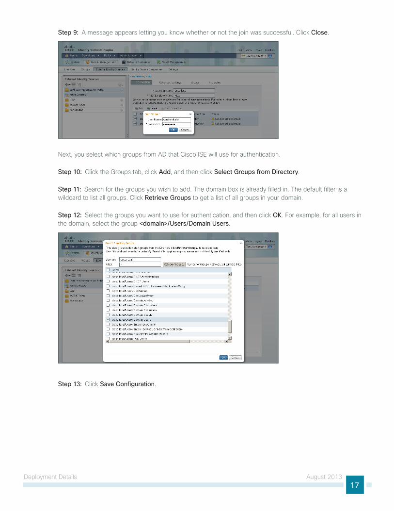
Step 9: A message appears letting you know whether or not the join was successful. Click Close.
next, you select which groups from AD that Cisco ISE will use for authentication.
Step 10: Click the groups tab, click Add, and then click Select Groups from Directory.
Step 11: Search for the groups you wish to add. the domain box is already filled in. the default filter is a wildcard to list all groups. Click Retrieve Groups to get a list of all groups in your domain.
Step 12: Select the groups you want to use for authentication, and then click OK. For example, for all users in the domain, select the group <domain>/Users/Domain Users.
Step 13: Click Save Configuration.

Deployment Details August 201318
Procedure 8 Disable IP Phone authorization policy
there is a default policy in place for Cisco IP Phones that have been profiled. this profile applies a downloadable access list on the port to which the phone is connected. Since there is no policy enforcement taking place at this point, this rule should be disabled.
Step 1: On the menu bar, mouse over Policy, and then click Authorization.
Step 2: For the Profiled Cisco IP Phones rule, click Edit, click the green check mark icon, choose Disabled, click Done, and then click Save.
Enabling Visibility to the LAN
1. Configure MAC Authentication Bypass
2. Configure 802.1X for wired users
3. Enable RADIuS in the access layer
4. Enable identity
5. Disable port security timers
6. Configure identity on Catalyst 4500
PR
OC
ESS
Cisco ISE now has a baseline configuration. the next step is to configure Cisco ISE with an authentication policy and to configure the switches for identity by using Cisco Prime lMS 4.2 and the Cisco trustSec Work Center.
Procedure 1 Configure MAC Authentication Bypass
MAC Authentication Bypass (MAB) allows you to configure specific machine MAC addresses on the switch to bypass the authentication process. For monitor mode, this is required, since you aren’t enforcing authentication. You configure MAB to allow any MAC address to authenticate for both the wired and wireless networks.
Step 1: Mouse over Policy, and then choose Authentication. the Policy type is Rule-Based.
there are already two default rules in place, MAB and Dot1X.

Deployment Details August 201319
Step 2: next to Wired_MAB, click the + symbol. to the right of the Wired_MAB condition name, click the gear symbol, and then choose Add Condition from Library.
Step 3: In the Select Condition list, next to Compound Condition, click the > symbol.
Step 4: Choose Wireless_MAB, and then click anywhere to continue.
Step 5: For the MAB policy, click the black triangle to the right of the and…. this brings up the identity store used for the MAB rule.
next, you change the options on the Internal users database, which is used for profiling.
Step 6: next to Internal Endpoints, click the +.

Deployment Details August 201320
Step 7: In this example deployment, all endpoints are allowed to authenticate. Set the following values, click anywhere in the window in order to continue, and then click Save:
• If authentication failed—Continue
• If user not found—Continue
• If process failed—Drop
Procedure 2 Configure 802.1X for wired users
there is already a Dot1X rule configured on the engine. Although in this example deployment you aren’t deploying any wired endpoints with 802.1X supplicants at this point, you should still configure this rule to prepare for the next phase of an identity deployment.
Step 1: Mouse over Policy, and then, from the menu, choose Authentication.
Step 2: Rename the rule Wired-Dot1X. this differentiates the rule from a wireless 802.1X rule.
Step 3: For the Wired-Dot1X rule, click the black triangle to the right of the and…. this brings up the identity store used for this rule.
the default identity store is the internal user database. For 802.1X, use the Active Directory server that you defined earlier.
Step 4: next to Internal users, click the + symbol. this enables you to edit the identity store and the parameters.

Deployment Details August 201321
Step 5: In the Identity Source list, choose the previously defined AD server AD1, use the default options for this identity source, click anywhere in the window to continue, and then click Save.
Procedure 3 Enable RADIUS in the access layer
Step 1: In a web browser, connect to Cisco Prime lMS, for example: https://lms.cisco.local.
Step 2: Mouse over Work Centers, and then, from the trustSec section, choose Getting Started. this shows the network’s Cisco trustSec-readiness assessment, which verifies that the software versions support the identity features and that the switches are capable of running RADIuS.

Deployment Details August 201322
Cisco Prime lMS 4.2 supports trustSec 2.0 features. the trustSec 2.0 feature set did not include support for the Cisco Catalyst 4500 Series Switches. Alternate procedures are listed in this guide for configuring these switches.
Tech Tip
next, you configure identity by enabling RADIuS on the switch.
Step 3: Mouse over Work Centers, and then, from the trustSec section, choose RADIUS Configuration.
Step 4: In the RADIuS-capable devices table, select the switches for which you want to enable RADIuS, and then click Next.
Step 5: On the Configure RADIuS page, select RADIUS Group, and in the RADIUS Group Name box, enter ISE-Group, and then in the Shared Key box, use the value used in previous procedures.
Step 6: In the RADIuS Server Details section, click Add.
Step 7: In the pop-up window, for the RADIuS server IP address, enter 10.4.48.41, and then click Save and add another.
Step 8: For the second RADIuS server, enter 10.4.48.42, and then click Save. the RADIuS server group has been configured.

Deployment Details August 201323
Step 9: In the AAA Configuration section, make sure that only Enable for 802.1X / MAB AAA is selected. A message about not configuring AAA for web authentication appears. Click OK.
Step 10: On the Configure RADIuS page, click Next.
You can review the ClI commands that will be pushed to the switch by clicking Preview CLI.
Tech Tip
Step 11: Enter a job description, and then click Finish. Deployment begins immediately.
Step 12: When you receive the message regarding the addition of AAA commands, click Yes, and then on the pop-up window generated after the job is created, click OK.

Deployment Details August 201324
Procedure 4 Enable identity
the identity configuration enables monitor mode on the switch. this enables both 802.1X and MAC Authentication Bypass (MAB); however, no authentication policy is enabled. this allows the ports to be monitored with no disruption to current network activity.
Step 1: Mouse over Work Centers, and then, under the trustSec section, choose Identity Configuration.
Step 2: In the navigator pane, click Enable Identity on Interfaces.
Step 3: In the Filter list, choose the switch that was previously configured for RADIuS, in the Port Group Selector pane, select All Groups, and then click Next.

Deployment Details August 201325
Step 4: Select the check boxes next to the ports for which you want to enable identity, and then click Next.
next, you configure monitor mode.
Step 5: In the Identity mode to be configured section, move the Security Mode slider to Monitor, which is the default.
Step 6: In the Authentication profile and host mode section, set the following values:
• Define Authentication Profile—802.1X, then MAB
• Define Host Mode—MultiAuth
• Action to be taken on security violation—No Change
In the MAC Configuration section, make sure only Enable MAC Move is selected.

Deployment Details August 201326
Step 7: In the Additional Configurations section, select Advanced Options, and then in the Adhoc commands box, enter the following command, and then click Next.
device-sensor accounting
For device profiling, you need to enable the IOS Sensor feature on the switch to include DHCP and CDP information in the RADIuS messages sent from the switch to Cisco ISE. the IOS Sensor feature relies on information from the DHCP snooping feature that was enabled in the Campus Wired lAn Design guide. this feature is not supported on the Cisco Catalyst 2960S access layer switches. If you want to use device profiling in the access layer, you will need to deploy Cisco Catalyst 3560, 3750, or 4500 Series Switches.
Tech Tip
Identity configuration is complete. next, you create a deployment job in order to deliver the configuration to the switch.

Deployment Details August 201327
Step 8: In the Job Description box, enter a description, click Finish, and then click OK.
You can review the ClI commands that will be pushed to the switch by clicking Preview CLI.
Tech Tip
the global commands added to the switch configuration at the completion of the previous two procedures are as follows.
radius-server host 10.4.48.41 auth-port 1645 acct-port 1646
radius-server host 10.4.48.42 auth-port 1645 acct-port 1646
radius-server key [key]aaa group server radius ISE-Group
server 10.4.48.41 auth-port 1645 acct-port 1646
server 10.4.48.42 auth-port 1645 acct-port 1646
aaa authentication dot1x default group ISE-Group
aaa authorization network default group ISE-Group
aaa authorization configuration default group ISE-Group
aaa accounting dot1x default start-stop group ISE-Group
radius-server vsa send accounting
radius-server vsa send authentication
authentication mac-move permit
dot1x system-auth-control
device-sensor accounting

Deployment Details August 201328
the interface commands added at the completion of the previous two procedures are as follows.
interface [interface] authentication host-mode multi-auth
authentication open
authentication order dot1x mab
authentication port-control auto
mab
dot1x pae authenticator
Procedure 5 Disable port security timers
the current CVD incorporates the use of port security to provide a level of security and prevent rogue devices from being connected. However, 802.1X also provides this functionality and there can be conflicts when both are enabled on a port at the same time. this is particularly true of inactivity timers since both port security and 802.1X each have their own set of timers. the conflict causes 802.1X to re-authenticate every time the port security time out is reached. to avoid this issue, port security timers need to be disabled.
Step 1: Connect to the Cisco Prime lMS server by browsing to https://lms.cisco.local.
Step 2: navigate to Configuration > Tools > NetConfig. this opens the Job Browser.
Step 3: Click Create. this enables you to configure a new job.
Step 4: Select Port based, and then click Go.
Step 5: In the tree, next to All Devices, click the + symbol, select the switch you are configuring, and then click Next.
In this example, only one switch is being configured, but you can select multiple switches to accommodate a large deployment. the group Selector allows you to choose switches by pre-defined groups or by model.
Tech Tip
Step 6: Select Define an Ad-Hoc Rule. A new screen is displayed.
Step 7: For the ad-hoc rule, in the Object Type list, choose Port.
Step 8: In the Variable list, choose Identity_Security_Mode.
Step 9: In the Operator list, choose =, and then in the Value list, choose Monitor.

Deployment Details August 201329
Step 10: Click Add Rule Expression, and then click Next.
Step 11: In the task Selector, select Adhoc Task, and then click Next.
Step 12: Click Add Instance, and then, in the new window, enter the ClI commands necessary to remove the port security configuration.
no switchport port-security aging time
no switchport port-security aging type
no switchport port-security violation
Step 13: Click Applicable Devices, select the switch to which you want to apply this configuration, click Close, and then click Save.

Deployment Details August 201330
Step 14: After returning to the Add tasks window, click Next.
Step 15: Fill in a description for the job, and then click Next. the job is submitted for immediate deployment.
Step 16: Click Finish, and then when you receive a notice that the job was submitted successfully, click OK.
Procedure 6 Configure identity on Catalyst 4500
Cisco trustSec Work Center supports trustSec 2.0 features, but does not support Cisco Catalyst 4500. However, Catalyst 4500 does support all of the features in use. You have to configure these by using the netConfig feature of Cisco lMS. this procedure covers enabling RADIuS, configuring 802.1X in monitor mode, and disabling port security.
Step 1: Connect to the Cisco Prime lMS server by browsing to https://lms.cisco.local:1741.
Step 2: Mouse over Configuration, and then, from the tools section, choose NetConfig.
Step 3: In the netConfig Job Browser, click Create.
Step 4: Select Device Based for the netConfig Job type, and then click Go.
Step 5: In the Device Selector, expand All Devices, select the devices where you want to enable identity.
Step 6: In the task Selector, expand All Tasks, select Adhoc, and then click Next.

Deployment Details August 201331
Step 7: Click Add Instance, and then, in the new window, enter the ClI commands necessary to configure identity.
radius-server host 10.4.48.41 auth-port 1645 acct-port 1646
radius-server host 10.4.48.42 auth-port 1645 acct-port 1646
radius-server key [key]aaa group server radius ISE-Group
server 10.4.48.41 auth-port 1645 acct-port 1646
server 10.4.48.42 auth-port 1645 acct-port 1646
aaa authentication dot1x default group ISE-Group
aaa authorization network default group ISE-Group
aaa authorization configuration default group ISE-Group
aaa accounting dot1x default start-stop group ISE-Group
radius-server vsa send accounting
radius-server vsa send authentication
authentication mac-move permit
dot1x system-auth-control
device-sensor accounting
Step 8: Click Applicable Devices, select the switch to which you want to apply this configuration, and then click Close.
Step 9: For the command mode, choose Config, and then click Save.
Step 10: After returning to the Add tasks window, click Next.
Step 11: Fill in a description for the job, and then click Next. the job is submitted for immediate deployment.
Step 12: Click Finish, and then when you receive a notice that the job was submitted successfully, click OK.
Step 13: navigate to Configuration > Tools > NetConfig. this opens the Job Browser.
Step 14: Click Create. this enables you to configure a new job.
Step 15: Select Port based, and then click Go.
Step 16: In the tree, next to All Devices, click the + symbol, select the switch you are configuring, and then click Next.
In this example, only one switch is being configured, but you can select multiple switches to accommodate a large deployment. the group Selector allows you to choose switches by pre-defined groups or by model.
Tech Tip

Deployment Details August 201332
Step 17: Select Define an Ad-Hoc Rule. A new screen is displayed.
Step 18: For the ad-hoc rule, in the Rule text section, click Include.
Step 19: In the Include list section, expand Devices, and then select the switch you want to configure for identity.
Step 20: Choose the ports you want to configure for identity, and then click Include. the window closes.
Step 21: Move to step 3 of the wizard by clicking Next.
Step 22: In the task Selector, select Adhoc Task, and then click Next.
Step 23: Click Add Instance, and then, in the new window, enter the ClI commands necessary in order to enable monitor mode and remove the port security configuration.
authentication host-mode multi-auth
authentication open
authentication order dot1x mab
authentication port-control auto
mab
dot1x pae authenticator
no switchport port-security aging time
no switchport port-security aging type
no switchport port-security violation
Deployment Details August 201333
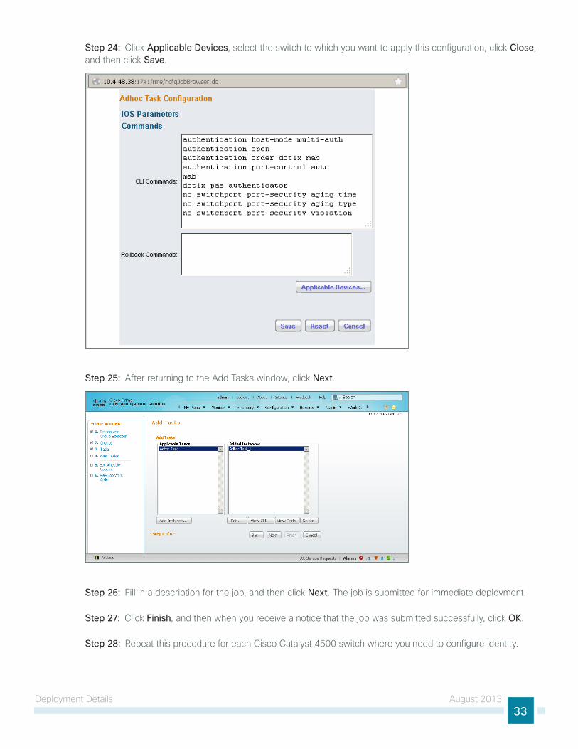
Step 24: Click Applicable Devices, select the switch to which you want to apply this configuration, click Close, and then click Save.
Step 25: After returning to the Add tasks window, click Next.
Step 26: Fill in a description for the job, and then click Next. the job is submitted for immediate deployment.
Step 27: Click Finish, and then when you receive a notice that the job was submitted successfully, click OK.
Step 28: Repeat this procedure for each Cisco Catalyst 4500 switch where you need to configure identity.

Deployment Details August 201334
Enabling Visibility to the Wireless Network
1. Configure 802.1X for wireless endpoints
2. Disable EAP-tlS on Cisco ISE
3. Add ISE as RADIuS authentication server
4. Add Cisco ISE as RADIuS accounting server
5. Enable client profiling
PR
OC
ESS
to authenticate wireless clients, you need to configure the wireless lAn controllers (WlC) to use the new Cisco ISE servers as RADIuS servers for authentication and accounting. the existing entry is disabled so that if there are any issues after moving to Cisco ISE, you can quickly restore the original configuration. Additionally, you configure the WlCs for DHCP profiling so that profiling information can be obtained from the DHCP requests from these clients and sent to the Cisco ISE.
Procedure 1 Configure 802.1X for wireless endpoints
to differentiate wireless users in the authentication logs, create a rule to identify when wireless users authenticate.
Step 1: In a browser, access the primary engine’s guI at http://ise-1.cisco.local and navigate to Policy > Authentication to open the Authentication Policy page.
Step 2: For the Default Rule, click the Actions button, and then choose Insert new row above. A new rule, Standard Policy 1, is created.
Step 3: Rename Standard Policy 1 to Wireless-Dot1X. In the Condition(s) box, click the + symbol, and then choose Select Existing Condition from Library.
Step 4: In the Select Condition list, next to Compound Condition, click the > symbol.
Deployment Details August 201335
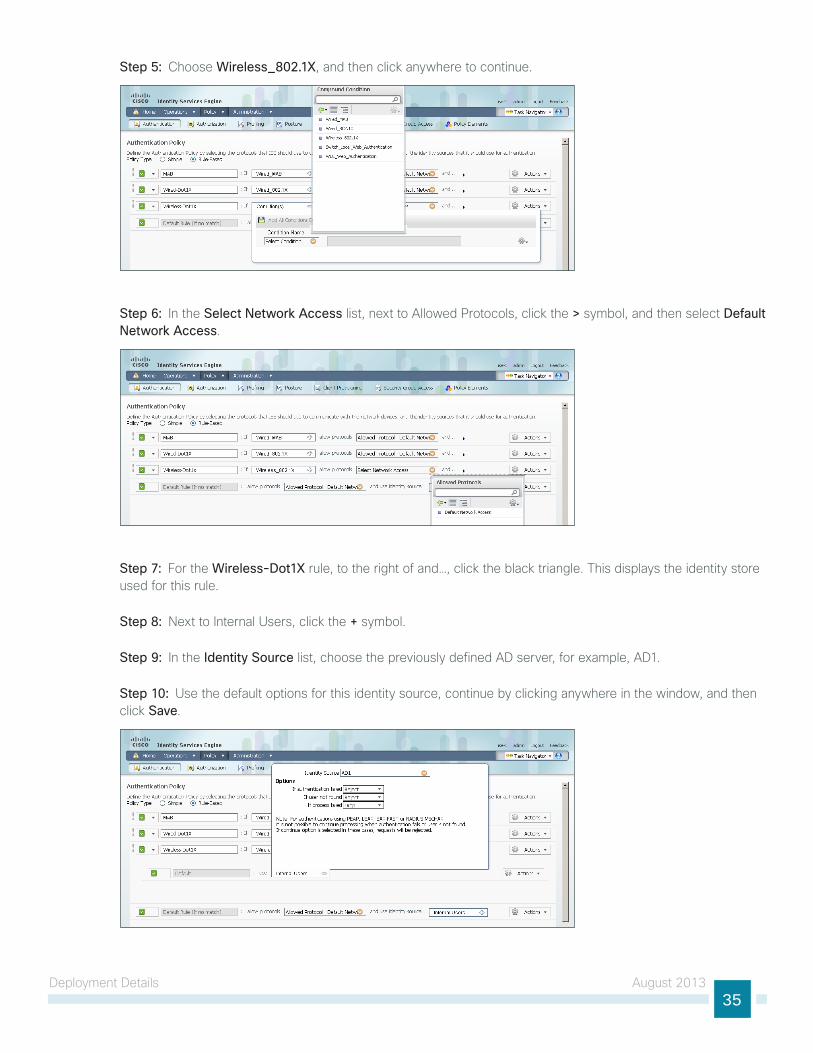
Step 5: Choose Wireless_802.1X, and then click anywhere to continue.
Step 6: In the Select Network Access list, next to Allowed Protocols, click the > symbol, and then select Default Network Access.
Step 7: For the Wireless-Dot1X rule, to the right of and…, click the black triangle. this displays the identity store used for this rule.
Step 8: next to Internal users, click the + symbol.
Step 9: In the Identity Source list, choose the previously defined AD server, for example, AD1.
Step 10: use the default options for this identity source, continue by clicking anywhere in the window, and then click Save.

Deployment Details August 201336
Procedure 2 Disable EAP-TLS on Cisco ISE
For wireless deployments that aren’t currently using digital certificates, you need to disable EAP-tlS in order to allow clients to log in. You will be deploying digital certificates in a later phase of this deployment.
Step 1: On the menu bar, mouse over Policy, and then, from the Policy Elements section of the menu, choose Results.
Step 2: In the left pane, double-click Authentication. this expands the options.
Step 3: Double-click Allowed Protocols, and then select Default Network Access.
Step 4: Clear the global Allow EAP-TLS check box and under the PEAP settings, clear the Allow EAP-TLS check box, and then click Save.
Procedure 3 Add ISE as RADIUS authentication server
Perform this procedure for every wireless lAn controller (WlC) in the architecture with the exception of the standalone guest WlC, if you have deployed one.
Step 1: navigate to the WlC console by browsing to https://wlc1.cisco.local.
Step 2: On the menu bar, click Security.
Step 3: In the left pane, under the RADIuS section, click Authentication.
Step 4: Click New. A new server is added.
Step 5: In the Server IP Address box, enter 10.4.48.41, and then enter your RADIuS shared secret.

Deployment Details August 201337
Step 6: next to Management, clear the Enable box, and then click Apply.
Step 7: Repeat Step 4 through Step 6 in order to add the secondary engine, 10.4.48.42, to the WlC configuration.
After adding Cisco ISE as a RADIuS server, disable the current RADIuS server in use. By disabling the server instead of deleting it, you can easily switch back if needed. Perform this procedure for every wireless lAn controller (WlC) in the architecture with the exception of the standalone guest WlC, if you have deployed one.
Step 8: On the RADIuS Authentication Servers screen, click the Server Index of the original RADIuS server, and then, for Server Status, select Disabled. Click Apply.
Step 9: On the RADIuS Authentication Servers screen, click Apply.
Procedure 4 Add Cisco ISE as RADIUS accounting server
Perform this procedure for every wireless lAn controller (WlC) in the architecture, with the exception of the standalone guest WlC, if you have deployed one.
Step 1: On the menu bar, click Security.
Step 2: In the left pane, under the RADIuS section, click Accounting.
Step 3: Click New. this adds a new server.

Deployment Details August 201338
Step 4: In the Server IP Address box, enter 10.4.48.41, enter your RADIuS shared secret, and then click Apply.
Step 5: Repeat Step 3 through Step 4 in order to add the secondary engine, 10.4.48.42, to the WlC configuration.
Step 6: On the RADIuS Accounting Servers screen, click the Server Index of the original RADIuS server, and then, for Server Status, select Disabled. Click Apply.
Step 7: On the RADIuS Accounting Servers screen, click Apply.
Procedure 5 Enable client profiling
You need to enable client profiling on the WlC in order to send DHCP and HttP information to the engine for endpoint profiling.
Step 1: On the WlC, navigate to WLANs, and then select the WlAn ID for the SSIDs you wish to monitor.
Step 2: On the Advanced tab, in the Client Profiling section, select DHCP Profiling.
Step 3: When the message appears about enabling DHCP Reqd and disabling local Auth, click OK.

Deployment Details August 201339
Step 4: In the Client Profiling section, select HTTP Profiling, and then click Apply.
Step 5: When a message appears saying that the WlAns need to be disabled, click OK.
the network infrastructure is now enabled for monitoring the network to determine what types of devices are connecting. Additionally, authentication using Cisco ISE is enabled for the wireless network. this is a good place in the deployment to test the deployment and monitor network access. Some organizations may not need to implement the next phase and choose to stop here.
Deploying Digital Certificates
1. Install certificate authority
2. Install trusted root certificate for domain
3. Install trusted root on AD server
4. Request a certificate for ISE from the CA
5. Download CA root certificate
6. Issue certificate for Cisco ISE
7. Install trusted root certificate in Cisco ISE
8. Install local certificate in Cisco ISE
9. Delete old certificate and request
PR
OC
ESS
In the next phase of deployment, you configure the infrastructure to support the use of digital certificates for user and machine authentication. using digital certificates when deploying 802.1X is a Cisco best practice. In this example deployment, you will be deploying digital certificates to Microsoft Windows XP and Windows 7 endpoints as well as to Apple Mac OS X devices. the certificate authority (CA) you will be using is the one built into Windows Server 2008 Enterprise, and you will install it as a standalone server.

Deployment Details August 201340
Procedure 1 Install certificate authority
there are six different role services that can be installed when configuring the certificate authority. For this deployment, you will install all of them.
Step 1: Install an enterprise root certificate authority on a Windows 2008 R2 Enterprise server.
For more information about installing a certificate authority, see the Microsoft Windows Server 2008 Active Directory Certificate Services Step-by-Step guide.
Reader Tip
Procedure 2 Install trusted root certificate for domain
Install a trusted root certificate on the AD controller in order to distribute it to the clients so that certificates from the CA server will be trusted.
Step 1: On the console of the AD controller, launch a web browser, and then connect to the certificate authority at the following: https://ca.cisco.local/certsrv
Step 2: Click Download a CA certificate, certificate chain, or CRL.
Step 3: Make sure the current certificate is selected and the DER encoding method is selected.
Step 4: Click Download CA Certificate, and then save the certificate file on the AD controller.
Step 5: On the AD console, navigate to Start > Administrative Tools > Group Policy Management.
Step 6: Expand Forest > Domains > [local domain] > Group Policy Objects.
Deployment Details August 201341
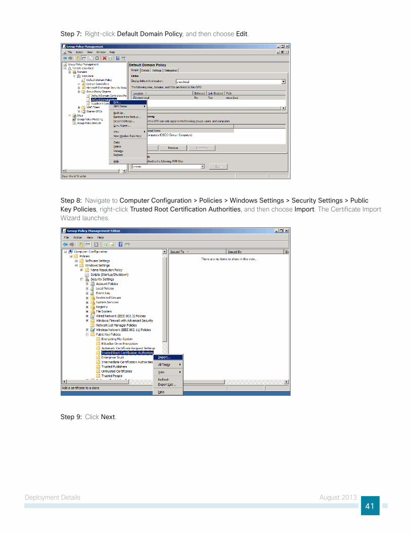
Step 7: Right-click Default Domain Policy, and then choose Edit.
Step 8: navigate to Computer Configuration > Policies > Windows Settings > Security Settings > Public Key Policies, right-click Trusted Root Certification Authorities, and then choose Import. the Certificate Import Wizard launches.
Step 9: Click Next.

Deployment Details August 201342
Step 10: Click Browse, locate the trusted root certificate saved in Step 2, and then click Next.
Step 11: Place the certificate in the trusted Root Certification Authorities certificate store, and then click Next.
Step 12: Click Finish. the certificate imports.
Step 13: Click OK to close the wizard.
Procedure 3 Install trusted root on AD server
In addition to configuring AD server to distribute the trusted root certificate to workstations, you need to install the certificate directly on the AD server. A group policy object (gPO) update takes care of this automatically. In this procedure, you will force the update to run immediately.
Step 1: On the AD console, navigate to Start > Run.
Step 2: type cmd, and then press Enter. A command window opens.

Deployment Details August 201343
Step 3: update the group policy.
C:\> gpupdate
Procedure 4 Request a certificate for ISE from the CA
In order to obtain a certificate from the CA, Cisco ISE needs to generate a signing request that will be used by the CA to generate a certificate.
Step 1: Connect to https://ise-1.cisco.local.
Step 2: Mouse over Administration, and then, from the System section of the menu, choose Certificates.
Step 3: under Certificate Operations, select Local Certificates.
Step 4: Click Add, and then choose Generate Certificate Signing Request.
Step 5: In the Certificate Subject box, after the “Cn=”, enter the fully qualified domain name (FQDn) of the Cisco ISE server, and then click Submit.

Deployment Details August 201344
Step 6: On the message acknowledging that the certificate was successfully generated, click OK.
Step 7: Click Certificate Signing Requests, select the check box next to the new request, and then click Export.
Step 8: Save the file to your local machine. You will use this file to generate a certificate on the CA for Cisco ISE.
Procedure 5 Download CA root certificate
Step 1: Browse to https://ca.cisco.local/certsrv.
Step 2: Click Download a CA certificate, certificate chain, or CRL.
Step 3: Make sure the current certificate is selected and the DER encoding method is selected.
Step 4: Click Download CA Certificate, and then save the certificate file on the local machine.
Procedure 6 Issue certificate for Cisco ISE
Step 1: Click Home. the CA’s home screen displays.
Step 2: Click Request a certificate.

Deployment Details August 201345
Step 3: Click advanced certificate request.
Step 4: In a text editor, such as notepad, open the certificate file saved in Procedure 4, “Request a certificate for ISE from the CA.”
Step 5: Select all the text, and then copy it to the clipboard.
Step 6: In the browser, on the Submit a Certificate Request or Renewal Request page, in the Saved Request box, paste the certificate contents.
Step 7: In the Certificate Template list, choose Web Server, and then click Submit.
Step 8: Select DER encoded, and then click Download certificate. the certificate saves to your local machine.
Procedure 7 Install trusted root certificate in Cisco ISE
Step 1: In the Cisco ISE interface, mouse over Administration, and then, from the System section of the menu, choose Certificates.
Step 2: Click Certificate Store, and then click Import.

Deployment Details August 201346
Step 3: Click Browse, and then locate the root CA certificate saved in Procedure 5, “Download CA root certificate.”
Step 4: Select Trust for client authentication, and then click Submit.
Procedure 8 Install local certificate in Cisco ISE
Step 1: In the Cisco ISE interface, mouse over Administration, and then, from the System section of the menu, choose Certificates.
Step 2: Click Local Certificates.
Step 3: Click Add, and then choose Bind CA Certificate.
Step 4: Click Browse and locate the certificate saved from Procedure 6, “Issue certificate for Cisco ISE.”

Deployment Details August 201347
Step 5: In the Protocol section, select both EAP and Management Interface. When you receive a message that selecting the Management Interface check box will require the Cisco ISE appliance to restart, click OK, and then click Submit.
Step 6: When you receive a message that the Cisco ISE appliance will restart, click OK.
Procedure 9 Delete old certificate and request
now that you have imported the local certificate into Cisco ISE, you need to delete the old self-signed certificate as well as the certificate signing request generated previously.
Step 1: In the Cisco ISE interface, mouse over Administration, and then, in the System section, choose Certificates.
Step 2: Click Local Certificates.
Step 3: Select the box next to the self-signed certificate. this is the certificate issued by the Cisco ISE appliance and not the certificate issued by the CA that was just imported.
Step 4: Click Delete, and then click OK.
Step 5: Click Certificate Signing Requests.

Deployment Details August 201348
Step 6: Select the box next to the certificate signing request that was created in Procedure 4, “Request a certificate for ISE from the CA.”
Step 7: Click Delete, and then click OK.
Enabling 802.1X Authentication
1. Create user authentication policies
2. Create machine authentication policies
3. Enable certificates
4. Enable EAP-tlS
PR
OC
ESS
You will configure Cisco ISE policies to support 802.1X authentication using digital certificates for both wired and wireless users.
Procedure 1 Create user authentication policies
An authentication profile is used to determine how a certificate will be used for authentication. You will create an authentication profile for user authentication using certificates.
Step 1: In Cisco ISE, mouse over Administration, and then, in the Identity Management section, choose External Identity Sources.
Step 2: In the left pane, click Certificate Authentication Profile, and then click Add.
Step 3: give the profile a meaningful name, and in the Principal Username X509 Attribute list, choose Subject Alternative Name.
Deployment Details August 201349
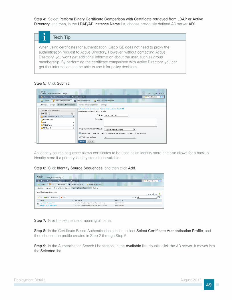
Step 4: Select Perform Binary Certificate Comparison with Certificate retrieved from LDAP or Active Directory, and then, in the LDAP/AD Instance Name list, choose previously defined AD server AD1.
When using certificates for authentication, Cisco ISE does not need to proxy the authentication request to Active Directory. However, without contacting Active Directory, you won’t get additional information about the user, such as group membership. By performing the certificate comparison with Active Directory, you can get that information and be able to use it for policy decisions.
Tech Tip
Step 5: Click Submit.
-
An identity source sequence allows certificates to be used as an identity store and also allows for a backup identity store if a primary identity store is unavailable.
Step 6: Click Identity Source Sequences, and then click Add.
Step 7: give the sequence a meaningful name.
Step 8: In the Certificate Based Authentication section, select Select Certificate Authentication Profile, and then choose the profile created in Step 2 through Step 5.
Step 9: In the Authentication Search list section, in the Available list, double-click the AD server. It moves into the Selected list.

Deployment Details August 201350
Step 10: In the Advanced Search list Settings section, select Treat as if the user was not found and proceed to the next store in the sequence, and then click Submit.
Procedure 2 Create machine authentication policies
You will create an authentication profile for machine authentication using certificates.
Step 1: In Cisco ISE, mouse over Administration, and then, in the Identity Management section, choose External Identity Sources.
Step 2: In the left pane, click Certificate Authentication Profile, and then click Add.
Step 3: give the profile a meaningful name, and in the Principal Username X509 Attribute list, choose Common Name.
Deployment Details August 201351
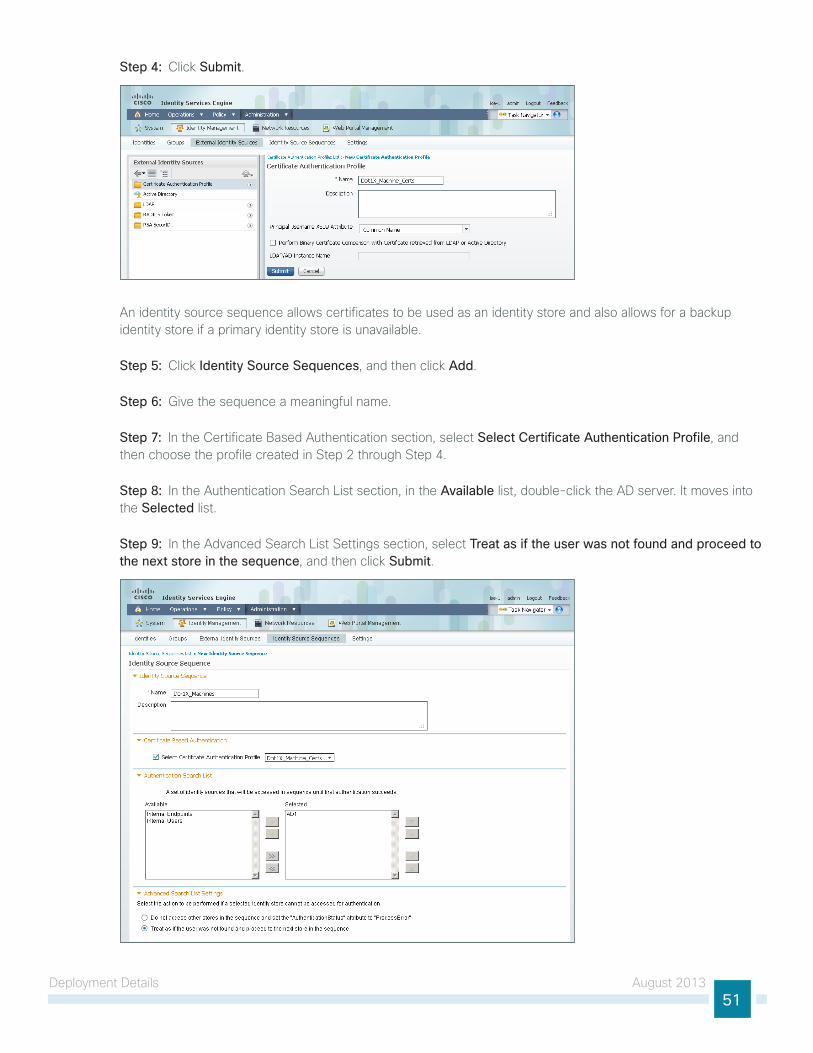
Step 4: Click Submit.
An identity source sequence allows certificates to be used as an identity store and also allows for a backup identity store if a primary identity store is unavailable.
Step 5: Click Identity Source Sequences, and then click Add.
Step 6: give the sequence a meaningful name.
Step 7: In the Certificate Based Authentication section, select Select Certificate Authentication Profile, and then choose the profile created in Step 2 through Step 4.
Step 8: In the Authentication Search list section, in the Available list, double-click the AD server. It moves into the Selected list.
Step 9: In the Advanced Search list Settings section, select Treat as if the user was not found and proceed to the next store in the sequence, and then click Submit.
Deployment Details August 201352
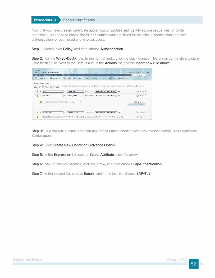
Procedure 3 Enable certificates
now that you have created certificate authentication profiles and identity source sequences for digital certificates, you need to enable the 802.1X authentication policies for machine authentication and user authentication for both wired and wireless users.
Step 1: Mouse over Policy, and then choose Authentication.
Step 2: For the Wired-Dot1X rule, to the right of and…, click the black triangle. this brings up the identity store used for this rule. next to the Default rule, in the Actions list, choose Insert new rule above.
Step 3: give the rule a name, and then next to the Enter Condition box, click the box symbol. the Expression Builder opens.
Step 4: Click Create New Condition (Advance Option).
Step 5: In the Expression list, next to Select Attribute, click the arrow.
Step 6: next to network Access, click the arrow, and then choose EapAuthentication.
Step 7: In the second list, choose Equals, and in the last list, choose EAP-TLS.

Deployment Details August 201353
Step 8: Click the gear icon at the end of the condition, and then choose Add Attribute/Value.
Step 9: In the Expression list, next to Select Attribute, click the arrow.
Step 10: next to Radius, click the arrow, and then select User-name.
Step 11: In the second list, choose Starts with, and in the last box, type host/ and then click OK.
Step 12: next to Internal users, click the + symbol.

Deployment Details August 201354
Step 13: In the Identity Source list, choose the identity source sequence for machine authentication that you created in Procedure 2, “Create machine authentication policies,” use the default options for this identity source, and then click anywhere in the window to continue.
You now create a rule for wired user authentication.
Step 14: next to the Default rule, in the Actions list, choose Insert new rule above.
Step 15: give the rule a name, and then next to the Enter Condition box, click the box symbol. the Expression Builder opens.
Step 16: Click Create New Condition (Advance Option).
Step 17: In the Expression list, next to Select Attribute, click the arrow.
Step 18: next to network Access, click the arrow, and then choose EapAuthentication.
Step 19: In the second list, choose Equals, and in the last list, choose EAP-TLS, and then click OK.
Step 20: next to Internal users, click the + symbol.

Deployment Details August 201355
Step 21: In the Identity Source list, choose the identity source sequence for machine authentication that you created in Procedure 1, “Create user authentication policies,” use the default options for this identity source, and then click anywhere in the window to continue.
Step 22: Click Save.
Step 23: Repeat Step 2 through Step 22 for the Wireless-Dot1X rule.
Procedure 4 Enable EAP-TLS
In a previous section, you disabled EAP-tlS. now that you are using digital certificates, you need to re-enable it.
Step 1: On the menu bar, mouse over Policy, and then in the Policy Elements section, choose Results.
Step 2: In the left pane, double-click Authentication. this expands the options.
Step 3: Double-click Allowed Protocols, and then choose Default Network Access.
Deployment Details August 201356
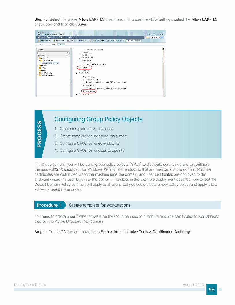
Step 4: Select the global Allow EAP-TLS check box and, under the PEAP settings, select the Allow EAP-TLS check box, and then click Save.
Configuring Group Policy Objects
1. Create template for workstations
2. Create template for user auto-enrollment
3. Configure gPOs for wired endpoints
4. Configure gPOs for wireless endpoints
PR
OC
ESS
In this deployment, you will be using group policy objects (gPOs) to distribute certificates and to configure the native 802.1X supplicant for Windows XP and later endpoints that are members of the domain. Machine certificates are distributed when the machine joins the domain, and user certificates are deployed to the endpoint where the user logs in to the domain. the steps in this example deployment describe how to edit the Default Domain Policy so that it will apply to all users, but you could create a new policy object and apply it to a subset of users if you prefer.
Procedure 1 Create template for workstations
You need to create a certificate template on the CA to be used to distribute machine certificates to workstations that join the Active Directory (AD) domain.
Step 1: On the CA console, navigate to Start > Administrative Tools > Certification Authority.

Deployment Details August 201357
Step 2: Expand the CA server, right-click Certificate Templates, and then choose Manage. the Certificate templates Console opens.
Step 3: Right-click the Computer template, and then choose Duplicate Template.
Step 4: For compatibility, make sure that Windows 2003 Server Enterprise is selected.
Step 5: In the Properties of new template window, click the General tab, and then give the template a name.
Step 6: On the Request Handling tab, select Allow private key to be exported, and then click CSPs.

Deployment Details August 201358
Step 7: Select Requests must use one of the following CSPs and Microsoft Enhanced Cryptographic Provider v1.0, and then click OK.

Deployment Details August 201359
Step 8: On the Security tab, click Domain Computers, and then for both Enroll and Autoenroll, make sure Allow is selected.
Step 9: use the defaults for the remaining tabs, and then click OK.
Step 10: Close the Certificate templates Console.

Deployment Details August 201360
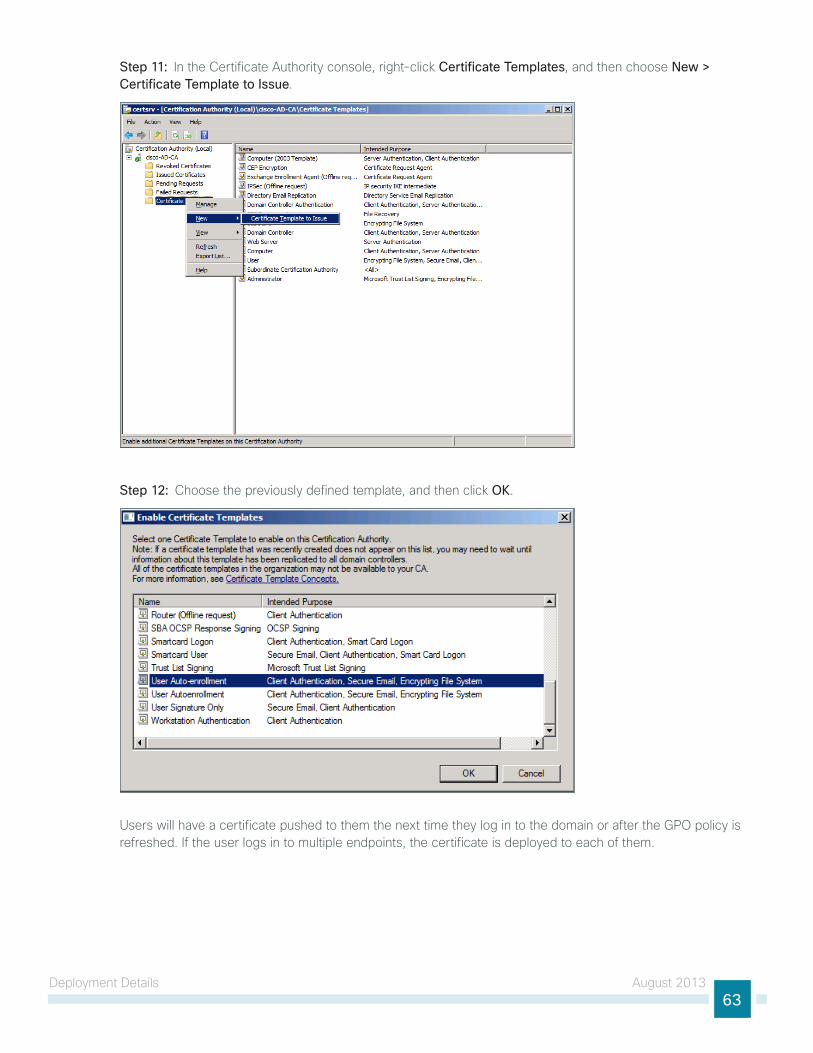
Step 11: In the Certificate Authority console, right-click Certificate Templates, and then choose New > Certificate Template to Issue.
Step 12: Choose the previously defined template, and then click OK.
When machines join the domain or when the gPO policy is refreshed (the default period is 90 minutes), the machine receives a machine certificate to allow for 802.1X machine authentication.

Deployment Details August 201361
Procedure 2 Create template for user auto-enrollment
this deployment uses group policy objects (gPOs) to have domain users auto-enroll to obtain a certificate when they log in to the domain. to enable auto-enrollment, you need to create a certificate template for these users.
Step 1: On the CA console, navigate to Start > Administrative Tools > Certification Authority.
Step 2: Expand the CA server, right-click Certificate Templates, and then choose Manage. the Certificate templates Console opens.
Step 3: Right-click the user template, and then choose Duplicate Template.
Step 4: For compatibility with Windows XP, make sure that Windows 2003 Server Enterprise is selected.
Step 5: In the Properties of new template window, click the General tab, and then give the template a name.
Step 6: On the Request Handling tab, select Allow private key to be exported, make sure Enroll subject without requiring any user input is selected, and then click CSPs.
Step 7: Select Requests must use one of the following CSPs and Microsoft Enhanced Cryptographic Provider v1.0, and then click OK.

Deployment Details August 201362
Step 8: On the Security tab, click Domain Users, and then for Read, Enroll, and Autoenroll, make sure Allow is selected.
Step 9: use the defaults for the remaining tabs, and then click OK.
Step 10: Close the Certificate templates Console.
Deployment Details August 201363
Step 11: In the Certificate Authority console, right-click Certificate Templates, and then choose New > Certificate Template to Issue.
Step 12: Choose the previously defined template, and then click OK.
users will have a certificate pushed to them the next time they log in to the domain or after the gPO policy is refreshed. If the user logs in to multiple endpoints, the certificate is deployed to each of them.

Deployment Details August 201364
Procedure 3 Configure GPOs for wired endpoints
this deployment uses gPOs to configure the 802.1X supplicant on wired endpoints running Windows XP SP3 and higher.
Step 1: On the CA console, navigate to Start > Administrative Tools > Group Policy Management.
Step 2: Expand Forest > Domain > local domain > Group Policy Objects.
Step 3: Right-click Default Domain Policy and click Edit. the group Policy Management Editor opens.
Step 4: In the group Policy Management Editor, navigate to Computer Configuration > Policies > Windows Settings > Security Settings.
Step 5: Right-click Wired Network (IEEE 802.3e) Policies, and then choose Create a New Wired Network Policy for Windows Vista and Later Releases.
Step 6: On the general tab, give the policy a name and description, and then make sure Use Windows Wired Auto Config service for clients is selected.
Step 7: On the Security tab, make sure Enable of IEEE 802.1X authentication for network access is selected.
Step 8: In the Network Authentication Method list, choose Microsoft: Smart Card or other certificate.
Step 9: In the Authentication Mode list, choose User or computer authentication.
Step 10: Click Properties.
Step 11: Make sure Use a certificate on this computer is selected, and then make sure Use simple certificate selection and Validate server certificate are selected.

Deployment Details August 201365
Step 12: In the Trusted Root Certification Authorities list, next to the root certificate for the CA, select the check box.
Step 13: Click OK. the certificate properties window closes.
Step 14: In the policy properties window, click Apply, and then click OK again.
Procedure 4 Configure GPOs for wireless endpoints
this deployment uses gPOs to configure the 802.1X supplicant for wireless endpoints running Windows XP SP3 and higher.
Step 1: On the CA console, navigate to Start > Administrative Tools > Group Policy Management.
Step 2: Expand Forest > Domain > local domain > Group Policy Objects.
Step 3: Right-click Default Domain Policy. the group Policy Management Editor opens.
Step 4: In the group Policy Management Editor, navigate to Computer Configuration > Policies > Windows Settings > Security Settings.
Step 5: Right-click Wireless Network (IEEE 802.11) Policies, and then choose Create a New Wireless Network Policy for Windows Vista and Later Releases.
Step 6: On the general tab, give the policy a name and description, and then make sure Use Windows WLAN AutoConfig service for clients is selected.

Deployment Details August 201366
Step 7: Click Add, and then choose Infrastructure.
Step 8: give the profile a name, enter the name of the SSID for the wireless network, and then click Add.
Step 9: On the Security tab, in the Authentication list, choose WPA2-Enterprise, and then in the Encryption list, choose AES.
Step 10: In the Select a network authentication method list, choose Microsoft: Smart Card or other certificate.
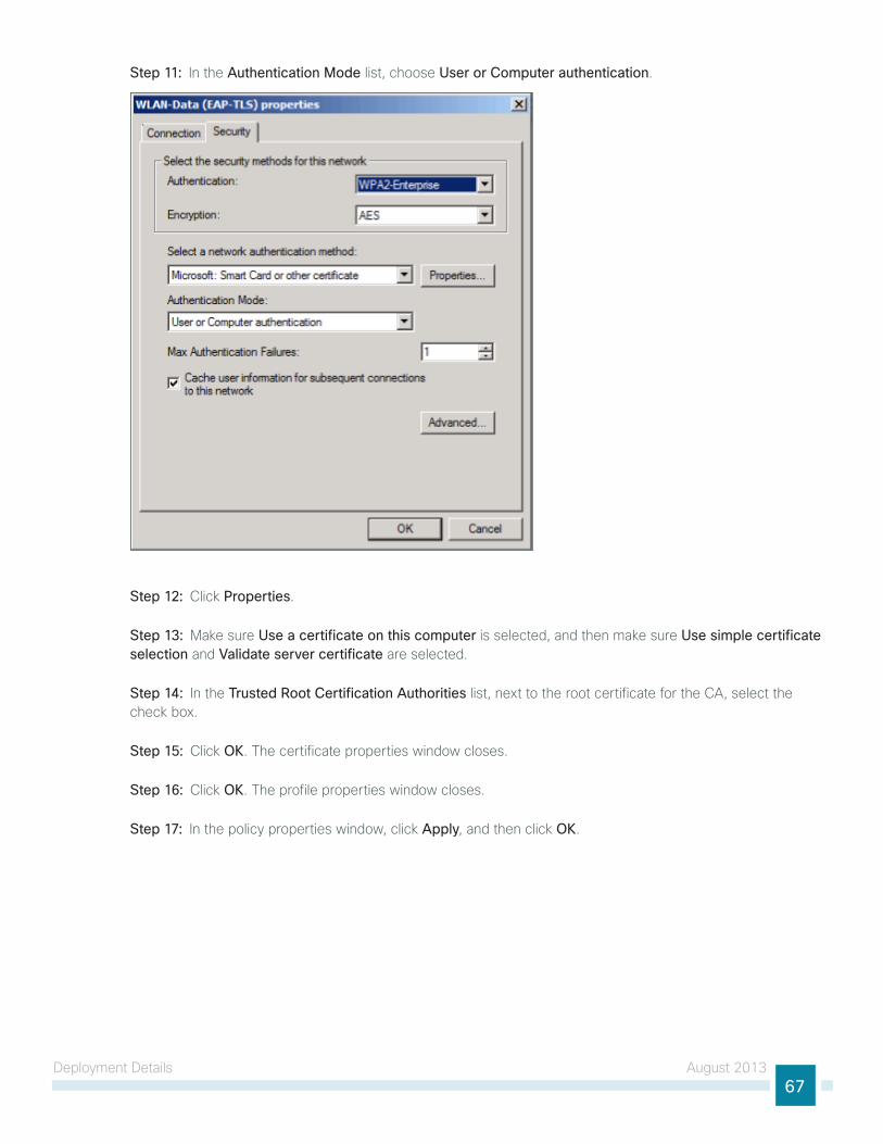
Deployment Details August 201367
Step 11: In the Authentication Mode list, choose User or Computer authentication.
Step 12: Click Properties.
Step 13: Make sure Use a certificate on this computer is selected, and then make sure Use simple certificate selection and Validate server certificate are selected.
Step 14: In the Trusted Root Certification Authorities list, next to the root certificate for the CA, select the check box.
Step 15: Click OK. the certificate properties window closes.
Step 16: Click OK. the profile properties window closes.
Step 17: In the policy properties window, click Apply, and then click OK.

Deployment Details August 201368
next, you create a policy for Windows XP clients.
Step 18: Right-click Wireless Network (IEEE 802.11) Policies, and then choose Create a New Windows XP Policy.
Step 19: On the general tab, give the policy a name and description, and then make sure Use Windows WLAN AutoConfig service for clients is selected.

Deployment Details August 201369
Step 20: In the Networks to access list, choose Any available network (access point preferred).
Step 21: On the Preferred networks tab, click Add, and then select Infrastructure.
Step 22: Enter the SSID for the network and give a description.
Step 23: In the Authentication list, choose WPA2, and then in the Encryption list, choose AES.
Step 24: On the IEEE 802.1X tab, in the EAP type list, choose Microsoft: Smart Card or other certificate.

Deployment Details August 201370
Step 25: In the Authentication Mode list, choose User or Computer authentication.
Step 26: Click Settings, make sure Use a certificate on this computer is selected, and then make sure Use simple certificate selection and Validate server certificate are selected.

Deployment Details August 201371
Step 27: In the Trusted Root Certification Authorities list, next to the root certificate for the CA, select the check box, and then click OK.
Step 28: In the profile properties window, click Apply, and then click OK.
Step 29: In the policy properties window, click Apply, and then click OK.
At this point, all endpoints running Windows XP SP3 and later will have a 802.1X supplicant configuration pushed to them the next time they log in to the domain or after the gPO policy is refreshed.

Deployment Details August 201372
Deploying Cisco AnyConnect on Windows Endpoints
1. Install Cisco AnyConnect
2. Install Profile Editor
3. Create wired profile
4. Create wireless profile
PR
OC
ESS
Cisco AnyConnect Secure Mobility Client 3.1 can be used as an 802.1X supplicant on Windows endpoints, using the network Access Manager module. In this example deployment, the network Access Manager is configured with both wired and wireless profiles using digital certificates.
Procedure 1 Install Cisco AnyConnect
to use Cisco AnyConnect Secure Mobility Client 3.1 as your 802.1X supplicant on Windows endpoints, you need to download the latest version from Cisco.com along with the Profile Editor. the client is distributed as an ISO image and will need to either be burned to a disk or mounted as a disk image by using a utility that provides this function. You need to be logged in as an administrator to install AnyConnect Secure Mobility Client.
the latest Cisco AnyConnect Secure Mobility client and Profile Editor can be downloaded from the following location: http://software.cisco.com/download/release.html?mdfid=283000185&softwareid=282364313&release=3.1.02040
to deploy the Cisco AnyConnect Secure Mobility Client to multiple workstations with the same policy, you can create a customized installation package. You need to copy all the files from the installation disk to a folder on the hard drive, for example, C:\AnyConnect. then, follow the procedure above to edit the profile. Copy the file (C:\ProgramData\Cisco\Cisco AnyConnect Secure Mobility Client\network Access Manager\system\configuration.xml) to C:\AnyConnect\Profiles\nam\configuration.xml.
Copy the contents of C:\AnyConnect to some form of removable media, for instance, CD, DVD, uSB drive, etc. You can then take this new installer package and run the installation on a workstation. the custom configuration file is loaded and ready for use.
Tech Tip
Step 1: Start the installer for the Cisco AnyConnect Secure Mobility Client by launching the Setup program on the disk.

Deployment Details August 201373
Step 2: Select AnyConnect Diagnostic and Reporting Tool and AnyConnect Network Access Manager, and then clear all of the other check boxes.
Step 3: Click Install Selected, verify the components selected to install, and then click OK.
Step 4: Click Accept. this accepts the license agreement.
Step 5: After the installation completes, click OK. You may be asked to restart the computer.
Procedure 2 Install Profile Editor
Step 1: locate the Profile Editor Installer downloaded previously, and then double-click it. the installation process starts.
the installation requires Java Runtime Environment 1.6 or higher. If you don’t have it installed, you are prompted to install it.
Step 2: If you are prompted to install Java Runtime Environment 1.6 or higher, click Next. this installs it.
Step 3: Click Next. the installation of Profile Editor continues.
Step 4: Click Typical, and then click Install.
Step 5: Click Finish. the installation completes.

Deployment Details August 201374
Procedure 3 Create wired profile
Step 1: launch the Profile Editor by navigating to Start > All Programs > Cisco > Cisco AnyConnect Profiler Editor > Network Access Manager Profile Editor.
Step 2: From the File menu, choose Open, and then select C:\ProgramData\Cisco\Cisco AnyConnect Secure Mobility Client\Network Access Manager\system\configuration.xml.
Step 3: Click Networks.
Step 4: Select the wired profile, and then click Edit.
Step 5: Enter a name for the profile, and then click Next.
Step 6: Select Authenticating Network, and then click Next.
Step 7: Select Machine and User Connection, and then click Next.
Step 8: For the machine authentication method, select EAP-TLS, and then click Next.
Step 9: For machine identity, enter an unprotected identity pattern. In this deployment, use host.[domain], and then click Next.
Step 10: For the user authentication method, select EAP-TLS, and then click Next.
Step 11: For user identity, enter an unprotected identity pattern. In this deployment, use [username]@[domain].

Deployment Details August 201375
Step 12: In the user Credentials section, select Prompt for Credentials, and then select Remember while User is Logged On.
Step 13: under Certificate Sources, select Smart Card or OS certificates, and then click Done.
Procedure 4 Create wireless profile
Step 1: In the Profile Editor, click Add. this creates a new wireless profile.
Step 2: Enter a name for the profile, and then, for group membership, select In all groups (Global).

Deployment Details August 201376
Step 3: In the Choose Your network Media section, select Wi-Fi (wireless) Network, enter the SSID of the wireless network, and then click Next.
Step 4: Select Authenticating Network, for the association mode, choose WPA2 Enterprise (AES), and then click Next.
Step 5: Select Machine and User Connection, and then click Next.
Step 6: For the machine authentication method, select EAP-TLS, and then click Next.
Step 7: For machine identity, enter an unprotected identity pattern. In this deployment, use host.[domain], and then click Next.
Step 8: For the user authentication method, select EAP-TLS, and then click Next.
Step 9: For user identity, enter an unprotected identity pattern. In this deployment, use [username]@[domain].
Step 10: In the user Credentials section, select Prompt for Credentials, and then select Remember while User is Logged On.
Step 11: under Certificate Sources, select Smart Card or OS certificates, and then click Done.
Step 12: From the File menu, choose Save. this updates the configuration file.
At this point, all Windows endpoints now have certificates deployed and are enabled to use 802.1X authentication. On the wireless network, any device that doesn’t have a certificate uses PEAP to gain access to the network. Monitor mode is running on the wired network, so endpoints that aren’t configured for 802.1X still get access by using MAC Authentication Bypass (MAB).
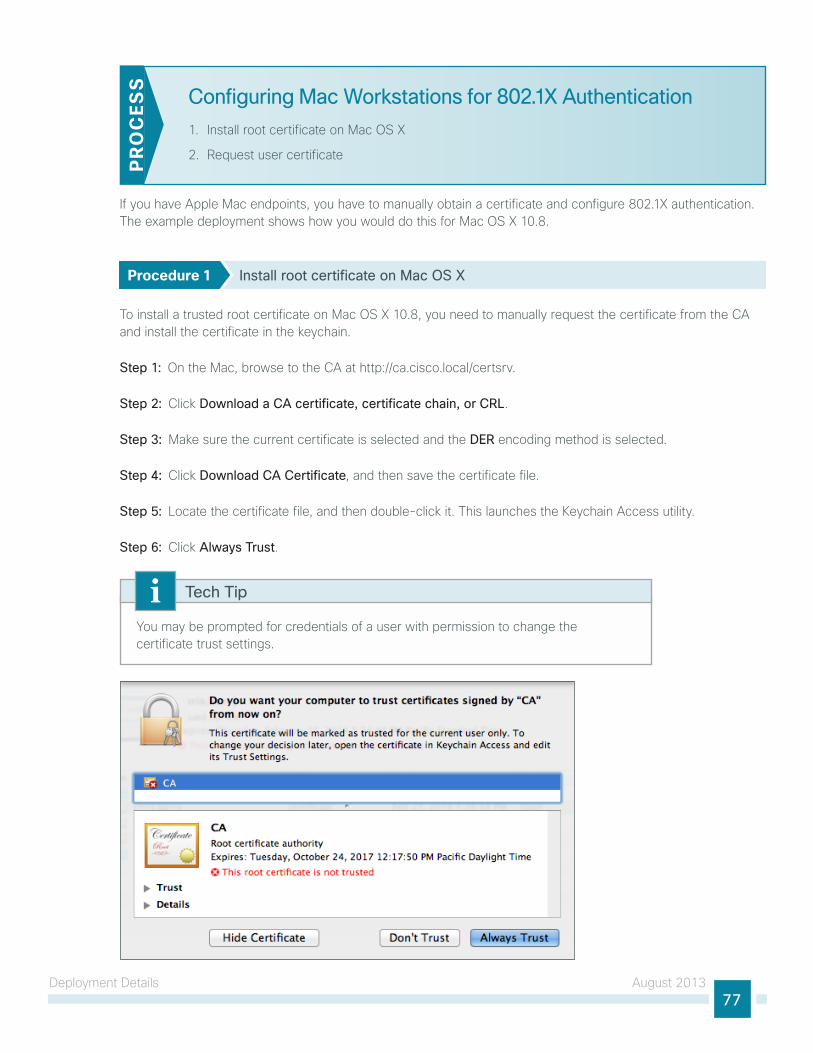
Deployment Details August 201377
Configuring Mac Workstations for 802.1X Authentication
1. Install root certificate on Mac OS X
2. Request user certificatePR
OC
ESS
If you have Apple Mac endpoints, you have to manually obtain a certificate and configure 802.1X authentication. the example deployment shows how you would do this for Mac OS X 10.8.
Procedure 1 Install root certificate on Mac OS X
to install a trusted root certificate on Mac OS X 10.8, you need to manually request the certificate from the CA and install the certificate in the keychain.
Step 1: On the Mac, browse to the CA at http://ca.cisco.local/certsrv.
Step 2: Click Download a CA certificate, certificate chain, or CRL.
Step 3: Make sure the current certificate is selected and the DER encoding method is selected.
Step 4: Click Download CA Certificate, and then save the certificate file.
Step 5: locate the certificate file, and then double-click it. this launches the Keychain Access utility.
Step 6: Click Always Trust.
You may be prompted for credentials of a user with permission to change the certificate trust settings.
Tech Tip
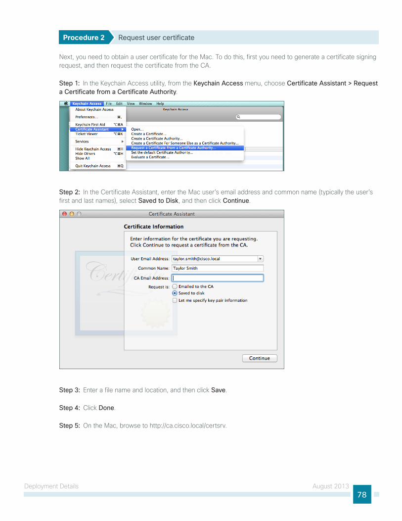
Deployment Details August 201378
Procedure 2 Request user certificate
next, you need to obtain a user certificate for the Mac. to do this, first you need to generate a certificate signing request, and then request the certificate from the CA.
Step 1: In the Keychain Access utility, from the Keychain Access menu, choose Certificate Assistant > Request a Certificate from a Certificate Authority.
Step 2: In the Certificate Assistant, enter the Mac user’s email address and common name (typically the user’s first and last names), select Saved to Disk, and then click Continue.
Step 3: Enter a file name and location, and then click Save.
Step 4: Click Done.
Step 5: On the Mac, browse to http://ca.cisco.local/certsrv.

Deployment Details August 201379
Step 6: Authenticate to the CA as the user for which you wish to obtain a certificate.
If you still have the browser window open from when you downloaded the trusted root certificate, click Home in the upper right corner. this returns you to the main page of the CA.
Tech Tip
Step 7: Click Request a certificate.
Step 8: Click advanced certificate request.
Step 9: In a text editor, such as textEdit, open the certificate request file saved in Step 3.
Step 10: Select all the text, and then copy it to the clipboard.
Step 11: In the browser, on the Submit a Certificate Request or Renewal Request page, in the Saved Request box, paste the certificate contents.
Step 12: In the Certificate Template list, choose User, and then click Submit.
Step 13: Select DER encoded, and then click Download certificate. this saves the certificate.
Step 14: In Finder, locate the saved certificate, and then double-click it. the Keychain Access utility imports the certificate.

Deployment Details August 201380
Configure Mac OS X SupplicantWhen accessing an 802.1X enabled network, Mac OS X will prompt you for a username and password. You will be connected to the network using PEAP and this will be stored in a configuration profile. to configure the 802.1X to use certificates and EAP-tlS in Mac OS X 10.8, you will manually create a configuration profile. this process is documented in detail in the white paper 802.1X Authentication available from Apple.
Any device that doesn’t have a certificate that wishes to use 802.1X will use PEAP to gain access to the network. Monitor mode is running on the wired network, so endpoints that aren’t configured for 802.1X still get access by using MAC Authentication Bypass (MAB).
Enable Authorizationthe network infrastructure is now configured for 8021.X authentication in monitor mode, and you have installed certificates on the endpoints and configured their 802.1X supplicants. upon successful authentication, the endpoint is granted full network access. However, monitor mode allows for endpoints that fail 802.1X to access the network using MAB. this is a good point in the deployment to stop to verify that certificates are deployed to all endpoints and supplicants are configured correctly without impacting the users’ network connectivity. You can monitor the logs to determine who is failing authentication and then correct those issues.
the next step would be to deploy some form of authorization to control what authenticated endpoints can access on the network. this next phase is called low-impact mode. In low-impact mode, endpoints are authenticated with either 802.1X or MAB. MAB is used for devices that require network access but either don’t support 802.1X or don’t have 802.1X configured. In this example, we are using MAB to authenticate IP phones and wireless access points that we will identify with device profiling. Any other device will have to successfully authenticate with 802.1X, or it will not have access to the network. After authentication, the endpoint is given full access to the network, but prior to authentication, the endpoint will only have access to the services necessary for authentication.
Enabling Authorization for Cisco IP Phones
1. Enable Cisco IP Phone policy
PR
OC
ESS
there is a built-in policy in Cisco ISE for Cisco IP Phones that was disabled in a previous section. You will enable this policy and create an authorization profile for Cisco IP Phones.
Procedure 1 Enable Cisco IP Phone policy
Step 1: Connect to http://ise-1.cisco.local.
Step 2: From the Policy menu, select Authorization.
Step 3: For the Profiled Cisco IP Phones rule, click Edit.
Step 4: Click the grey circle icon at the front of the rule, and then choose Enabled.
Step 5: Click Done, and then click Save.
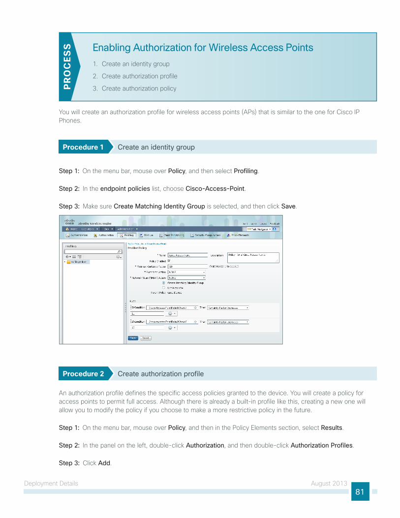
Deployment Details August 201381
Enabling Authorization for Wireless Access Points
1. Create an identity group
2. Create authorization profile
3. Create authorization policyPR
OC
ESS
You will create an authorization profile for wireless access points (APs) that is similar to the one for Cisco IP Phones.
Procedure 1 Create an identity group
Step 1: On the menu bar, mouse over Policy, and then select Profiling.
Step 2: In the endpoint policies list, choose Cisco-Access-Point.
Step 3: Make sure Create Matching Identity Group is selected, and then click Save.
Procedure 2 Create authorization profile
An authorization profile defines the specific access policies granted to the device. You will create a policy for access points to permit full access. Although there is already a built-in profile like this, creating a new one will allow you to modify the policy if you choose to make a more restrictive policy in the future.
Step 1: On the menu bar, mouse over Policy, and then in the Policy Elements section, select Results.
Step 2: In the panel on the left, double-click Authorization, and then double-click Authorization Profiles.
Step 3: Click Add.

Deployment Details August 201382
Step 4: name the profile Cisco_APs and give a description.
Step 5: Select DACL Name and in the list, make sure PERMIT_ALL_TRAFFIC is selected, and then click Submit.
Procedure 3 Create authorization policy
Step 1: On the menu bar, mouse over Policy, and then select Authorization.
Step 2: For the Default rule, on the right, click the black triangle symbol, and then select Insert New Rule Above. A new rule named Standard Rule 1 is created.
Step 3: Rename the rule Profiled Cisco APs.
Step 4: For the new rule, in the Conditions column, next to Any, click the + symbol.

Deployment Details August 201383
Step 5: From the list, next to Endpoint Identity Groups, click the > symbol and then next to Profiled, click the > symbol.
Step 6: Choose Cisco-Access-Point.
Step 7: under the Permissions column, next to AuthZ Profile, click the + symbol.
Step 8: In the list, next to Standard, click the > symbol, and then choose Cisco_APs.
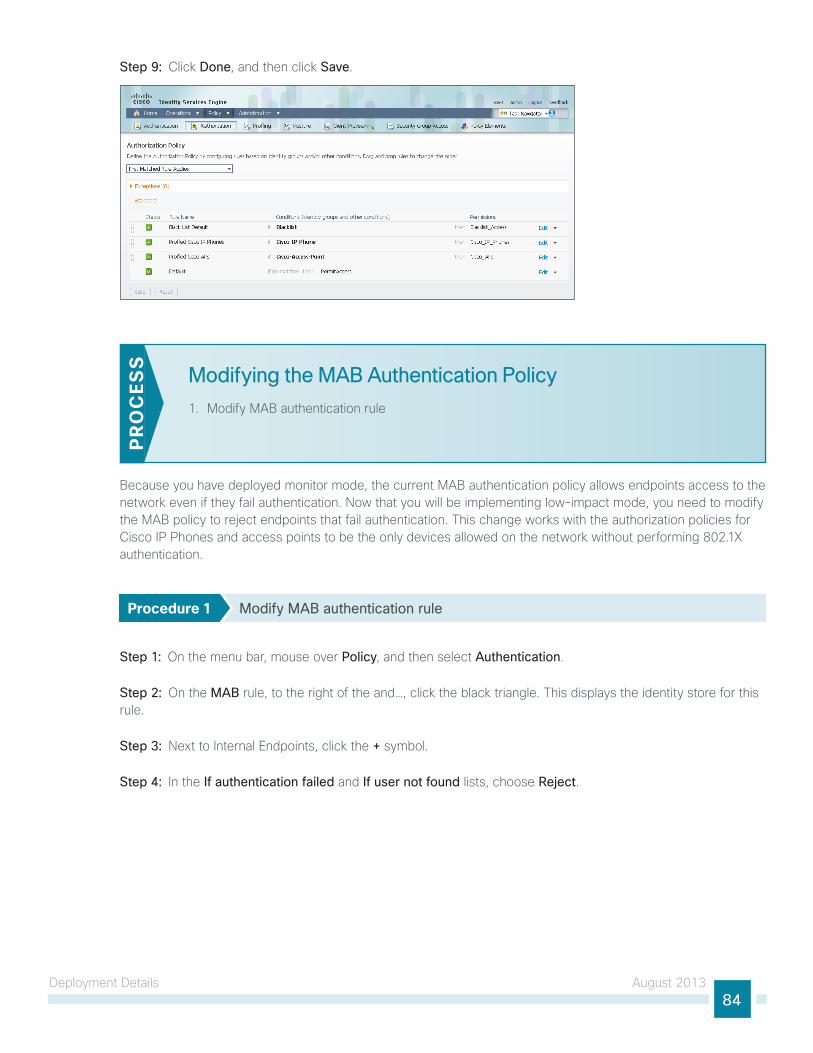
Deployment Details August 201384
Step 9: Click Done, and then click Save.
Modifying the MAB Authentication Policy
1. Modify MAB authentication rule
PR
OC
ESS
Because you have deployed monitor mode, the current MAB authentication policy allows endpoints access to the network even if they fail authentication. now that you will be implementing low-impact mode, you need to modify the MAB policy to reject endpoints that fail authentication. this change works with the authorization policies for Cisco IP Phones and access points to be the only devices allowed on the network without performing 802.1X authentication.
Procedure 1 Modify MAB authentication rule
Step 1: On the menu bar, mouse over Policy, and then select Authentication.
Step 2: On the MAB rule, to the right of the and…, click the black triangle. this displays the identity store for this rule.
Step 3: next to Internal Endpoints, click the + symbol.
Step 4: In the If authentication failed and If user not found lists, choose Reject.

Deployment Details August 201385
Step 5: Click anywhere in the window to continue, and then click Save.
Enabling Authorization for Wired Endpoints
1. Create authorization profile
2. Create authorization policy
3. Enable low-impact mode
4. Enable low impact mode on Catalyst 4500
5. Enable change of authorization
6. Enable CoA on Catalyst 4500
PR
OC
ESS
You will enable authorization for wired endpoints that authenticate using digital certificates. At this stage, once authenticated, the endpoint will be granted full access to the network. this policy can be modified if you choose a more restrictive policy in the future.
Procedure 1 Create authorization profile
An authorization profile defines the specific access policies granted to the device. You will create a profile for wired endpoints to permit full access.
Step 1: On the menu bar, mouse over Policy, and then in the Policy Elements section, select Results.
Step 2: In the panel on the left, double-click Authorization, and then double-click Authorization Profiles.
Step 3: Click Add.
Step 4: name the profile Wired_Dot1X and give a description.
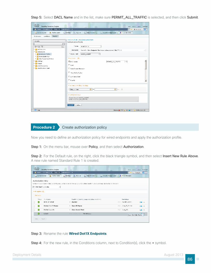
Deployment Details August 201386
Step 5: Select DACL Name and in the list, make sure PERMIT_ALL_TRAFFIC is selected, and then click Submit.
Procedure 2 Create authorization policy
now you need to define an authorization policy for wired endpoints and apply the authorization profile.
Step 1: On the menu bar, mouse over Policy, and then select Authorization.
Step 2: For the Default rule, on the right, click the black triangle symbol, and then select Insert New Rule Above. A new rule named Standard Rule 1 is created.
Step 3: Rename the rule Wired Dot1X Endpoints.
Step 4: For the new rule, in the Conditions column, next to Condition(s), click the + symbol.
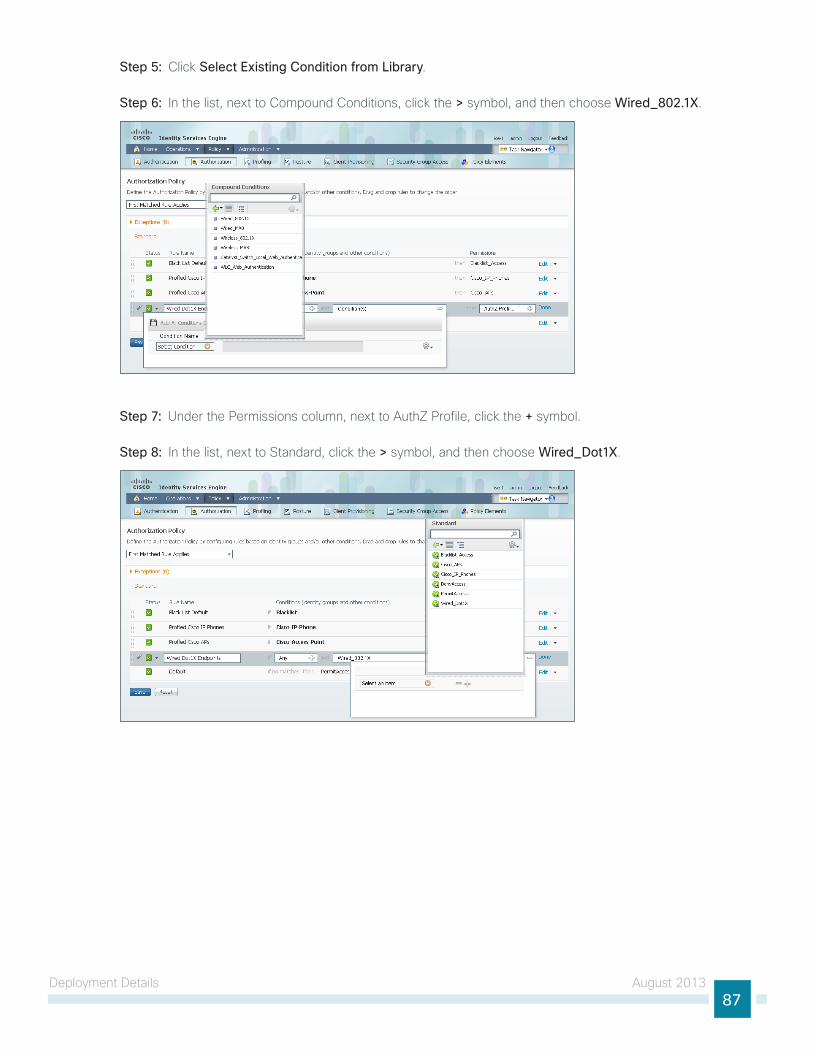
Deployment Details August 201387
Step 5: Click Select Existing Condition from Library.
Step 6: In the list, next to Compound Conditions, click the > symbol, and then choose Wired_802.1X.
Step 7: under the Permissions column, next to AuthZ Profile, click the + symbol.
Step 8: In the list, next to Standard, click the > symbol, and then choose Wired_Dot1X.
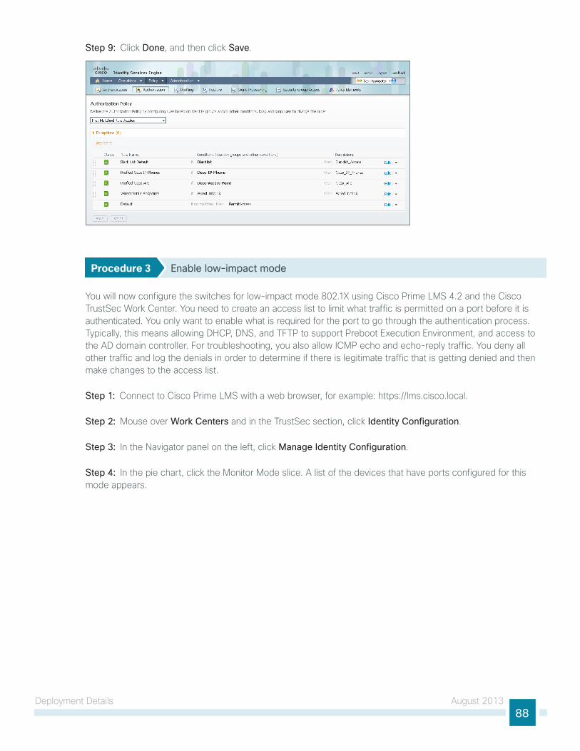
Deployment Details August 201388
Step 9: Click Done, and then click Save.
Procedure 3 Enable low-impact mode
You will now configure the switches for low-impact mode 802.1X using Cisco Prime lMS 4.2 and the Cisco trustSec Work Center. You need to create an access list to limit what traffic is permitted on a port before it is authenticated. You only want to enable what is required for the port to go through the authentication process. typically, this means allowing DHCP, DnS, and tFtP to support Preboot Execution Environment, and access to the AD domain controller. For troubleshooting, you also allow ICMP echo and echo-reply traffic. You deny all other traffic and log the denials in order to determine if there is legitimate traffic that is getting denied and then make changes to the access list.
Step 1: Connect to Cisco Prime lMS with a web browser, for example: https://lms.cisco.local.
Step 2: Mouse over Work Centers and in the trustSec section, click Identity Configuration.
Step 3: In the navigator panel on the left, click Manage Identity Configuration.
Step 4: In the pie chart, click the Monitor Mode slice. A list of the devices that have ports configured for this mode appears.

Deployment Details August 201389
Step 5: Select each switch with ports that you wish to move from monitor mode to low-impact mode, and then click Edit Mode.
Step 6: Select the check boxes next to the ports that you want to edit, and then click Next.
Step 7: In the Identity mode to be configured section, move the Security Mode slider to Low impact, and then in the Associated ACL box, enter PreAuth.
Step 8: . In the Authentication profile and host mode section, set the following values:
• Define Authentication Profile—802.1X, then MAB
• Define Host Mode—Multidomain
• Action to be taken on security violation—No Change
Step 9: In the MAC Configuration section, make sure only Enable MAC Move is selected.

Deployment Details August 201390
Step 10: In the Additional Configurations section, select Advanced Options. In the Adhoc commands box, enter the following commands, and then click Next.
ip device tracking
ip access-list extended PreAuth
permit ip any host 10.4.48.10
permit udp any eq bootpc any eq bootps
permit udp any any eq domain
permit udp any any eq tftp
permit icmp any any echo
permit icmp any any echo-reply
deny ip any any log

Deployment Details August 201391
Step 11: In the Job Description box, enter a description, and then click Finish. the job is submitted and a confirmation message appears. Click OK.
You can review the ClI commands that will be pushed to the switch by clicking Preview CLI.
Tech Tip
the global commands added to the switch configuration at the completion of this procedure are as follows.
ip device tracking
ip access-list extended PreAuth
permit ip any host 10.4.48.10
permit udp any eq bootpc any eq bootps
permit udp any any eq domain
permit udp any any eq tftp
permit icmp any any echo
permit icmp any any echo-reply
deny ip any any log
the interface commands added at the completion of this procedure are as follows.
interface [interface] ip access-group PreAuth in
authentication host-mode multi-domain
Procedure 4 Enable low impact mode on Catalyst 4500
the trustSec Work Center supports trustSec 2.0 features, which does not include support for Cisco Catalyst 4500. However, Catalyst 4500 does support all of the features in use. You will have to configure these using the netConfig feature of Cisco lMS. this procedure covers configuring 802.1X in low impact mode.
Step 1: Connect to the Cisco Prime lMS server by browsing to https://lms.cisco.local:1741.

Deployment Details August 201392
Step 2: Mouse over Configuration, and then, from the tools section, choose NetConfig.
Step 3: In the netConfig Job Browser, click Create.
Step 4: Select Device Based for the netConfig Job type, and then click Go.
Step 5: In the Device Selector, expand All Devices, select the devices where you want to enable low impact mode.
Step 6: In the task Selector, expand All Tasks, select Adhoc, and then click Next.
Step 7: Click Add Instance, and then, in the new window, enter the ClI commands necessary to configure low impact mode.
ip device tracking
ip access-list extended PreAuth
permit ip any host 10.4.48.10
permit udp any eq bootpc any eq bootps
permit udp any any eq domain
permit udp any any eq tftp
permit icmp any any echo
permit icmp any any echo-reply
deny ip any any log
Step 8: Click Applicable Devices, select the switch to which you want to apply this configuration, and then click Close.
Step 9: For the command mode, choose Config, and then click Save.
Step 10: After returning to the Add tasks window, click Next.
Step 11: Fill in a description for the job, and then click Next. the job is submitted for immediate deployment.
Step 12: Click Finish, and then when you receive a notice that the job was submitted successfully, click OK.
Step 13: navigate to Configuration > Tools > NetConfig. this opens the Job Browser.
Step 14: Click Create. this enables you to configure a new job.
Step 15: Select Port based, and then click Go.
Step 16: In the tree, next to All Devices, click the + symbol, select the switch you are configuring, and then click Next.
In this example, only one switch is being configured, but you can select multiple switches to accommodate a large deployment. the group Selector allows you to choose switches by pre-defined groups or by model.
Tech Tip

Deployment Details August 201393
Step 17: Select Define an Ad-Hoc Rule. this brings up a new screen.
Step 18: For the ad-hoc rule, in the Rule text section, click Include.
Step 19: In the Include list section, expand Devices, and then select the switch you want to configure for low impact mode.
Step 20: Choose the ports you want to configure for low impact mode, and then click Include. the window closes.
Step 21: Move to step 3 of the wizard by clicking Next.
Step 22: In the task Selector, select Adhoc Task, and then click Next.
Step 23: Click Add Instance, and then, in the new window, enter the ClI commands necessary in order to enable monitor mode and to remove the port security configuration.
ip access-group PreAuth in
authentication host-mode multi-domain

Deployment Details August 201394
Step 24: Click Applicable Devices, select the switch to which you want to apply this configuration, click Close, and then click Save.
Step 25: After returning to the Add tasks window, click Next.
Step 26: Fill in a description for the job, and then click Next. the job is submitted for immediate deployment.
Step 27: Click Finish, and then when you receive a notice that the job was submitted successfully, click OK.
Step 28: Repeat this procedure for each Cisco Catalyst 4500 where you need to configure low impact mode.
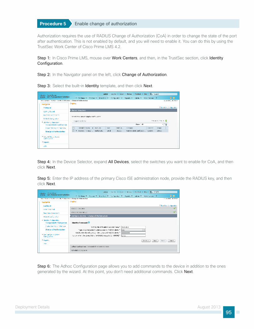
Deployment Details August 201395
Procedure 5 Enable change of authorization
Authorization requires the use of RADIuS Change of Authorization (CoA) in order to change the state of the port after authentication. this is not enabled by default, and you will need to enable it. You can do this by using the trustSec Work Center of Cisco Prime lMS 4.2.
Step 1: In Cisco Prime lMS, mouse over Work Centers, and then, in the trustSec section, click Identity Configuration.
Step 2: In the navigator panel on the left, click Change of Authorization.
Step 3: Select the built-in Identity template, and then click Next.
Step 4: In the Device Selector, expand All Devices, select the switches you want to enable for CoA, and then click Next.
Step 5: Enter the IP address of the primary Cisco ISE administration node, provide the RADIuS key, and then click Next.
Step 6: the Adhoc Configuration page allows you to add commands to the device in addition to the ones generated by the wizard. At this point, you don’t need additional commands. Click Next.
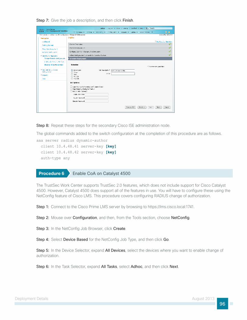
Deployment Details August 201396
Step 7: give the job a description, and then click Finish.
Step 8: Repeat these steps for the secondary Cisco ISE administration node.
the global commands added to the switch configuration at the completion of this procedure are as follows.
aaa server radius dynamic-author
client 10.4.48.41 server-key [key] client 10.4.48.42 server-key [key] auth-type any
Procedure 6 Enable CoA on Catalyst 4500
the trustSec Work Center supports trustSec 2.0 features, which does not include support for Cisco Catalyst 4500. However, Catalyst 4500 does support all of the features in use. You will have to configure these using the netConfig feature of Cisco lMS. this procedure covers configuring RADIuS change of authorization.
Step 1: Connect to the Cisco Prime lMS server by browsing to https://lms.cisco.local:1741.
Step 2: Mouse over Configuration, and then, from the tools section, choose NetConfig.
Step 3: In the netConfig Job Browser, click Create.
Step 4: Select Device Based for the netConfig Job type, and then click Go.
Step 5: In the Device Selector, expand All Devices, select the devices where you want to enable change of authorization.
Step 6: In the task Selector, expand All Tasks, select Adhoc, and then click Next.
Deployment Details August 201397
Step 7: Click Add Instance, and then, in the new window, enter the ClI commands necessary to enable change of authorization.
aaa server radius dynamic-author
client 10.4.48.41 server-key [key] client 10.4.48.42 server-key [key] auth-type any
Step 8: Click Applicable Devices, select the switch to which you want to apply this configuration, click Close, choose Config for the command mode, and then click Save.
Step 9: After returning to the Add tasks window, click Next.
Step 10: Fill in a description for the job, and then click Next. the job is submitted for immediate deployment.
Step 11: Click Finish, and then when you receive a notice that the job was submitted successfully, click OK.
Step 12: Repeat this procedure for each Cisco Catalyst 4500 switch where you want to enable RADIuS change of authorization.
Enabling Authorization for Wireless Endpoints
1. Create authorization profile
2. Create authorization policyPR
OC
ESS
You will enable authorization for wireless endpoints that authenticate using digital certificates. At this stage, once authenticated, the endpoint will be granted full access to the network. this policy can be modified if you choose a more restrictive policy in the future.
Procedure 1 Create authorization profile
An authorization profile defines the specific access policies granted to the device. You will create a policy for wireless endpoints to permit full access. By default, a client is given full access when joining the wireless network, so you will not need to define an access list at this point.
Step 1: In a browser, access the primary engine’s guI at http://ise-1.cisco.local. On the menu bar, mouse over Policy, and then in the Policy Elements section, select Results.
Step 2: In the panel on the left, double-click Authorization, and then double-click Authorization Profiles.
Step 3: Click Add.
Step 4: name the profile Wireless_Dot1X and give a description.

Deployment Details August 201398
Step 5: In the Access Type list, make sure ACCESS_ACCEPT is selected, and then click Submit.
Procedure 2 Create authorization policy
now you need to define an authorization policy for wireless endpoints and apply the authorization profile.
Step 1: On the menu bar, mouse over Policy, and then select Authorization.
Step 2: For the Default rule, on the right, click the black triangle symbol, and then select Insert New Rule Above. A new rule named Standard Rule 1 is created.
Step 3: Rename the rule Wireless Dot1X Endpoints.
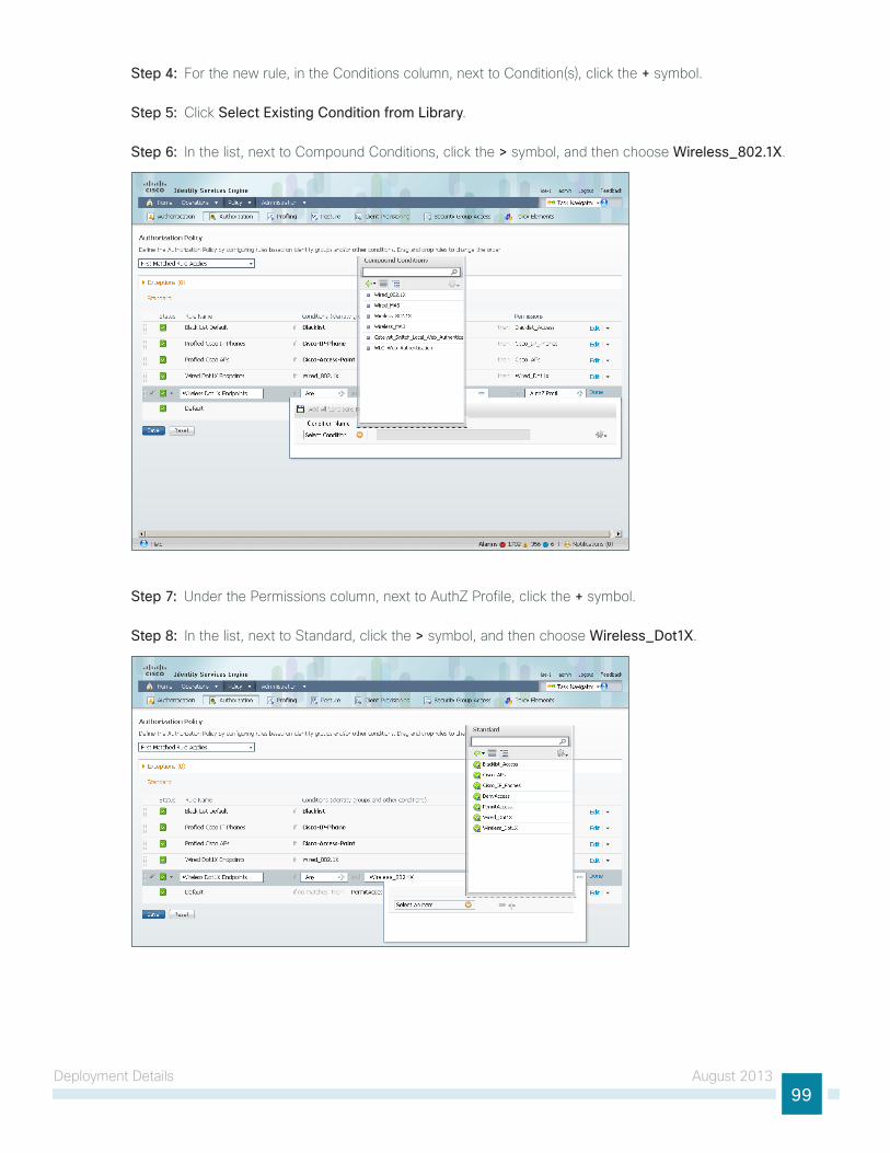
Deployment Details August 201399
Step 4: For the new rule, in the Conditions column, next to Condition(s), click the + symbol.
Step 5: Click Select Existing Condition from Library.
Step 6: In the list, next to Compound Conditions, click the > symbol, and then choose Wireless_802.1X.
Step 7: under the Permissions column, next to AuthZ Profile, click the + symbol.
Step 8: In the list, next to Standard, click the > symbol, and then choose Wireless_Dot1X.
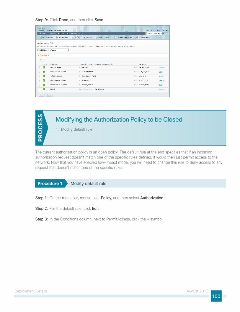
Deployment Details August 2013100
Step 9: Click Done, and then click Save.
Modifying the Authorization Policy to be Closed
1. Modify default rule
PR
OC
ESS
the current authorization policy is an open policy. the default rule at the end specifies that if an incoming authorization request doesn’t match one of the specific rules defined, it would then just permit access to the network. now that you have enabled low-impact mode, you will need to change this rule to deny access to any request that doesn’t match one of the specific rules.
Procedure 1 Modify default rule
Step 1: On the menu bar, mouse over Policy, and then select Authorization.
Step 2: For the default rule, click Edit.
Step 3: In the Conditions column, next to PermitAccess, click the + symbol.

Deployment Details August 2013101
Step 4: In the list, next to Standard, click the > symbol, and then choose DenyAccess.
Step 5: Click Done, and then click Save.

Deployment Details August 2013102
Enabling EAP Chaining
1. Enable EAP Chaining
2. Create authentication policy
3. Create authorization profile
4. Create authorization rule
5. Configure AnyConnect wired profile
6. Configure AnyConnect wireless profile
PR
OC
ESS
You have deployed both machine certificates and user certificates to Microsoft Windows workstations. However, only one of the certificates is used for authentication—the user certificate when a user is logged in and the machine certificate when one isn’t. EAP Chaining allows you to authenticate using both certificates by using the Cisco AnyConnect Secure Mobility Client 3.1.
Procedure 1 Enable EAP Chaining
Step 1: Connect to https://ise-1.cisco.local.
Step 2: On the menu bar, mouse over Policy, and then, from the Policy Elements section of the menu, choose Results.
Step 3: In the left pane, double-click Authentication. this expands the options.
Step 4: Double-click Allowed Protocols, and then select Default Network Access.
Step 5: Select Enable EAP Chaining, and then click Save.
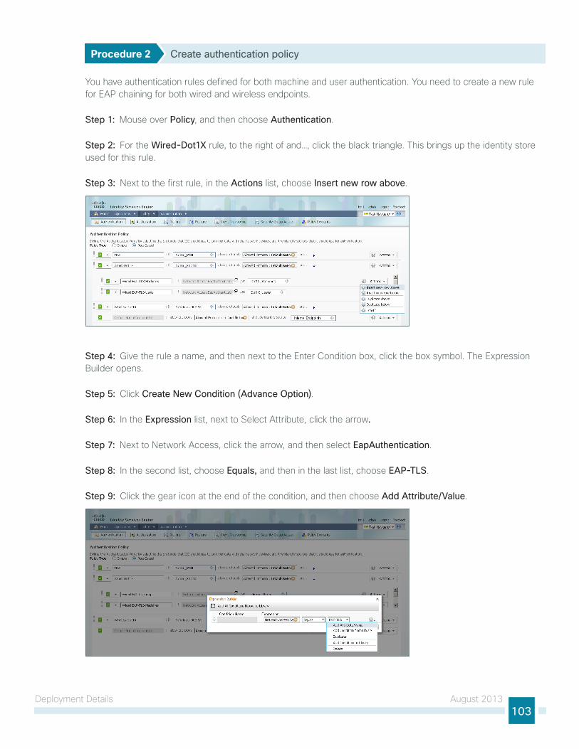
Deployment Details August 2013103
Procedure 2 Create authentication policy
You have authentication rules defined for both machine and user authentication. You need to create a new rule for EAP chaining for both wired and wireless endpoints.
Step 1: Mouse over Policy, and then choose Authentication.
Step 2: For the Wired-Dot1X rule, to the right of and…, click the black triangle. this brings up the identity store used for this rule.
Step 3: next to the first rule, in the Actions list, choose Insert new row above.
Step 4: give the rule a name, and then next to the Enter Condition box, click the box symbol. the Expression Builder opens.
Step 5: Click Create New Condition (Advance Option).
Step 6: In the Expression list, next to Select Attribute, click the arrow.
Step 7: next to network Access, click the arrow, and then select EapAuthentication.
Step 8: In the second list, choose Equals, and then in the last list, choose EAP-TLS.
Step 9: Click the gear icon at the end of the condition, and then choose Add Attribute/Value.

Deployment Details August 2013104
Step 10: In the Expression list, next to Select Attribute, click the arrow.
Step 11: next to Radius, click the arrow, and then choose User-name.
Step 12: In the second list, choose Equals, and then in the last box, type anonymous, and then click OK.
Step 13: next to Internal users, click the + symbol.
Step 14: In the Identity Source list, choose the identity source sequence for machine authentication that you created in Procedure 2, “Create machine authentication policies,” use the default options for this identity source, and then click anywhere in the window to continue.
Step 15: Click Save.
Step 16: Repeat Step 2 through Step 15 for the Wireless-Dot1X rule.

Deployment Details August 2013105
Procedure 3 Create authorization profile
An authorization profile defines the specific access policies granted to the device. You will create a policy to permit full access for devices that pass both user and machine authentication. Although there is already a built-in profile that permits full access, creating a new one will allow you to modify the policy if you choose to make a more restrictive policy in the future.
Step 1: On the menu bar, mouse over Policy, and then in the Policy Elements section, click Results.
Step 2: In the panel on the left, double-click Authorization, and then double-click Authorization Profiles.
Step 3: Click Add.
Step 4: name the profile User+Macine-Cert and give a description.
Step 5: Select DACL Name and in the list, choose PERMIT_ALL_TRAFFIC, and then click Submit.
Procedure 4 Create authorization rule
now you need to define an authorization policy and apply the authorization profile.
Step 1: On the menu bar, mouse over Policy, and then select Authorization.
Step 2: For the Profiled Cisco APs rule, on the right, click the black triangle symbol, and then select Insert New Rule Below. A new rule named Standard Rule 1 is created.
Step 3: Rename the rule EAP Chaining Machine andUser.

Deployment Details August 2013106
Step 4: For the new rule, in the Conditions column, next to Condition(s), click the + symbol.
Step 5: Click Create New Condition (Advance Option).
Step 6: under Expression, next to Select Attribute, click the arrow. the menu opens.
Step 7: next to network Access, click the > symbol, and then choose EapAuthentication.
Step 8: In the first list, choose Equals, and then, in the second list, choose EAP-TLS.
Step 9: Click the gear icon at the end of the rule, and then select Add Attribute/Value.
Step 10: In the new rule, under Expression, next to Select Attribute, click the arrow. the menu opens.
Step 11: next to network Access, click the > symbol, and then choose EapTunnel.
Step 12: In the first list, choose Equals, and then, in the second list, choose EAP-FAST.
Step 13: Click the gear icon at the end of the rule, and then select Add Attribute/Value.
Step 14: In the new rule, under Expression, next to Select Attribute, click the arrow. the menu opens.
Step 15: next to network Access, click the > symbol, and then choose EapChainingResult.
Step 16: In the first list, choose Equals, and then, in the second list, choose User and machine both succeeded then click anywhere to continue.
Step 17: In the Permissions section, next to AuthZ Profile(s), click the + symbol.
Step 18: In the Select an item list, next to Standard, click the > symbol.
Step 19: Choose the user+Machine-Cert authorization profile that you created in Procedure 3, “Create authorization profile.”
Step 20: Click Done, and then click Save.
Procedure 5 Configure AnyConnect wired profile
the AnyConnect client was installed in the process “Deploying Cisco AnyConnect on Windows Endpoints.” You now configure the Cisco AnyConnect Secure Mobility Client to use EAP Chaining.
Step 1: On the client running AnyConnect, launch the Profile Editor by navigating to Start > All Programs > Cisco > Cisco AnyConnect Profiler Editor > Network Access Manager Profile Editor.
Step 2: From the File menu, choose Open, and then select C:\ProgramData\Cisco\Cisco AnyConnect Secure Mobility Client\Network Access Manager\system\configuration.xml.

Deployment Details August 2013107
First, you will create a wired profile for EAP Chaining.
Step 3: Click Networks, and then click Add.
Step 4: Enter a name for the profile, select Wired (802.3) Network, and then click Next.
Step 5: Select Authenticating Network, and then click Next.
Step 6: Select Machine and User Connection, and then click Next.
Step 7: For the machine authentication method, select EAP-FAST.
Step 8: In the Inner Methods based on Credentials Source section, select Authenticate using a certificate and Send client certificate using EAP-TLS in the tunnel.
Step 9: Make sure Use PACs is selected, and then click Next.
Step 10: For the Certificates tab, click Next. this accepts the default values.
Step 11: For the PAC Files tab, click Next. this accepts the default values.
Step 12: Enter an unprotected identity pattern. In this deployment, use host/anonymous.

Deployment Details August 2013108
Step 13: Enter a protected identity pattern. In this deployment, use host/[username].[domain], and then click Next.
Step 14: For the user authentication method, select EAP-FAST.
Step 15: In the Inner Methods based on Credentials Source section, select Authenticate using a certificate and Send client certificate using EAP-TLS in the tunnel.
Step 16: Make sure Use PACs is selected, and then click Next.
Step 17: For the Certificates tab, click Next. this accepts the default values.
Step 18: For the PAC Files tab, click Next. this accepts the default values.
Step 19: Enter an unprotected identity pattern. In this deployment, use anonymous.
Step 20: Enter a protected identity pattern. In this deployment, use [username]@[domain].

Deployment Details August 2013109
Step 21: In the user Credentials section, select Prompt for Credentials, and then select Remember while User is Logged On.
Step 22: under Certificate Sources, select Smart Card or OS certificates, and then click Done.
Procedure 6 Configure AnyConnect wireless profile
You will now create a wireless profile for EAP Chaining.
Step 1: Click Networks, and then click Add.
Step 2: Enter a name for the profile.

Deployment Details August 2013110
Step 3: In the Choose Your network Media section, select Wi-Fi (wireless) Network. For SSID, enter your wireless SSID, and then click Next.
Step 4: Select Authenticating Network, choose WPA2 Enterprise (AES) for Association Mode, and then click Next.
Step 5: Select Machine and User Connection, and then click Next.
Step 6: For the machine authentication method, select EAP-FAST.
Step 7: In the Inner Methods based on Credentials Source section, select Authenticate using a certificate and Send client certificate using EAP-TLS in the tunnel.
Step 8: Make sure Use PACs is selected, and then click Next.
Step 9: For the Certificates tab, click Next. this accepts the default values.
Step 10: For the PAC Files tab, click Next. this accepts the default values.
Step 11: Enter an unprotected identity pattern. In this deployment, use host/anonymous.
Step 12: Enter a protected identity pattern. In this deployment, use host/[username].[domain], and then click Next.
Step 13: For the user authentication method, select EAP-FAST.
Step 14: In the Inner Methods based on Credentials Source section, select Authenticate using a certificate and Send client certificate using EAP-TLS in the tunnel.

Deployment Details August 2013111
Step 15: Make sure Use PACs is selected, and then click Next.
Step 16: For the Certificates tab, click Next. this accepts the default values.
Step 17: For the PAC Files tab, click Next. this accepts the default values.
Step 18: Enter an unprotected identity pattern. In this deployment, use anonymous.
Step 19: Enter a protected identity pattern. In this deployment, use [username]@[domain].
Step 20: In the user Credentials section, select Prompt for Credentials, and then select Remember while User is Logged On.
Step 21: under Certificate Sources, select Smart Card or OS certificates, and then click Done.
Step 22: From the File menu, choose Save. this updates the configuration file.
Enabling Downloadable Access Lists
1. Add Active Directory groups to ISE
2. Create wired access list
3. Create authorization profile
4. Create authorization policy
5. Configure WlC for authorization
PR
OC
ESS
You have now configured access for any user who authenticates successfully to be granted full access to the network. the next step will be to provide differentiated access to users based on their Active Directory (AD) group. You will create an authorization policy that verifies the user’s AD group and then applies an access list to the switch or wireless access point for that user.
Procedure 1 Add Active Directory groups to ISE
Step 1: In a browser, access the primary engine’s guI at http://ise-1.cisco.local.
Step 2: Mouse over Administration, and then, from the Identity Management section of the menu, choose External Identity Sources.
Step 3: In the left panel, click Active Directory.
Step 4: Click the groups tab, click Add, and then click Select Groups from Directory.
Step 5: Search for the groups you wish to add. the domain box is already filled in. the default filter is a wildcard to list all groups. Click Retrieve Groups to get a list of all groups in your domain.
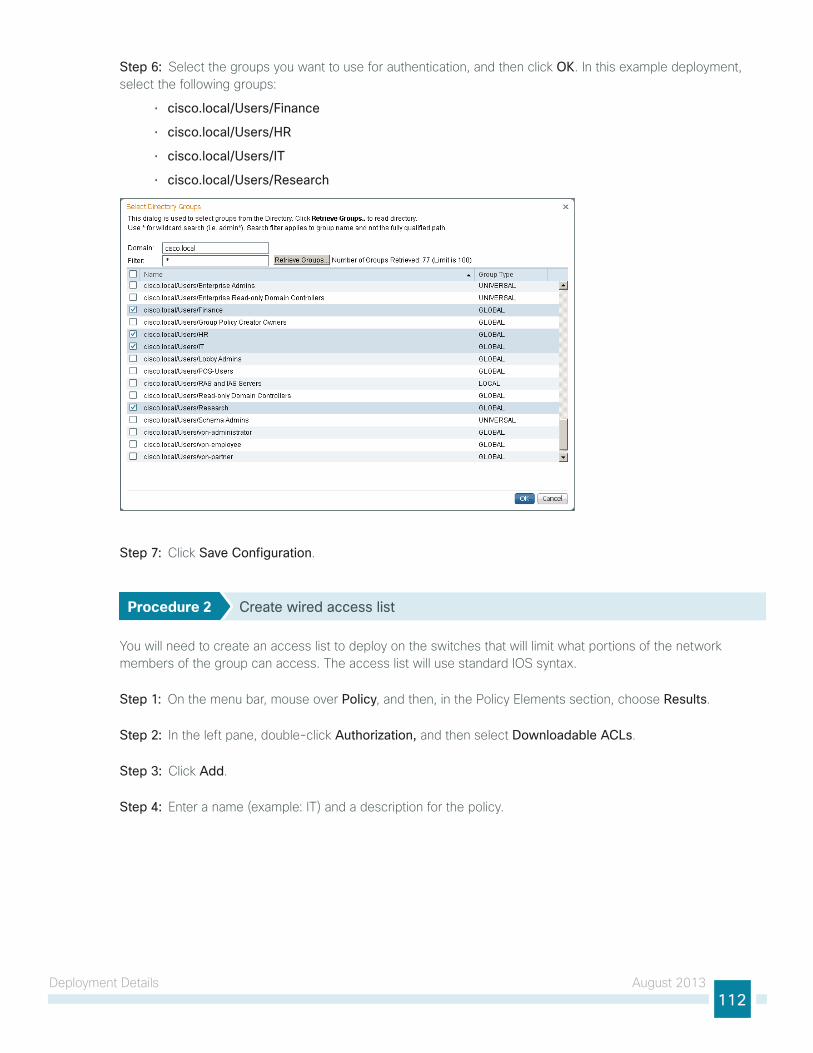
Deployment Details August 2013112
Step 6: Select the groups you want to use for authentication, and then click OK. In this example deployment, select the following groups:
• cisco.local/Users/Finance
• cisco.local/Users/HR
• cisco.local/Users/IT
• cisco.local/Users/Research
Step 7: Click Save Configuration.
Procedure 2 Create wired access list
You will need to create an access list to deploy on the switches that will limit what portions of the network members of the group can access. the access list will use standard IOS syntax.
Step 1: On the menu bar, mouse over Policy, and then, in the Policy Elements section, choose Results.
Step 2: In the left pane, double-click Authorization, and then select Downloadable ACLs.
Step 3: Click Add.
Step 4: Enter a name (example: It) and a description for the policy.

Deployment Details August 2013113
Step 5: In the DACl content section, enter the ACl by using IOS syntax, and then click Submit.
Procedure 3 Create authorization profile
An authorization profile defines the specific access policies granted to the device. You will create a policy to apply an access list to the access device to limit what the endpoint has access to on the network.
Step 1: On the menu bar, mouse over Policy, and then, in the Policy Elements section, choose Results.
Step 2: In the left pane, double-click Authorization, and then select Authorization Profiles.
Step 3: Click Add.
Step 4: Enter a name (example: It) and a description for the policy.
Step 5: In the Common task section, select DACL Name, and then select the ACl that you configured in Procedure 2, “Create wired access list.” In the example, the ACl is “It.”
Step 6: In the Common task section, select Airespace ACL Name, and then enter the name of the ACl that you are applying to the WlC. In this example, the ACl is “It.”
Step 7: Click Submit.
Procedure 4 Create authorization policy
Step 1: On the menu bar, mouse over Policy, and then click Authorization.
Step 2: For the Wired Dot1X Endpoints rule, on the right, click the black triangle symbol, and then select Insert New Rule Above. A new rule named Standard Rule 1 is created.
Step 3: Rename Standard Rule 1 to IT.
Step 4: In the Condition(s) list, choose the + symbol, and then click Create New Condition (Advance Option).
Step 5: under Expression, next to Select Attribute, click the arrow. the menu opens.
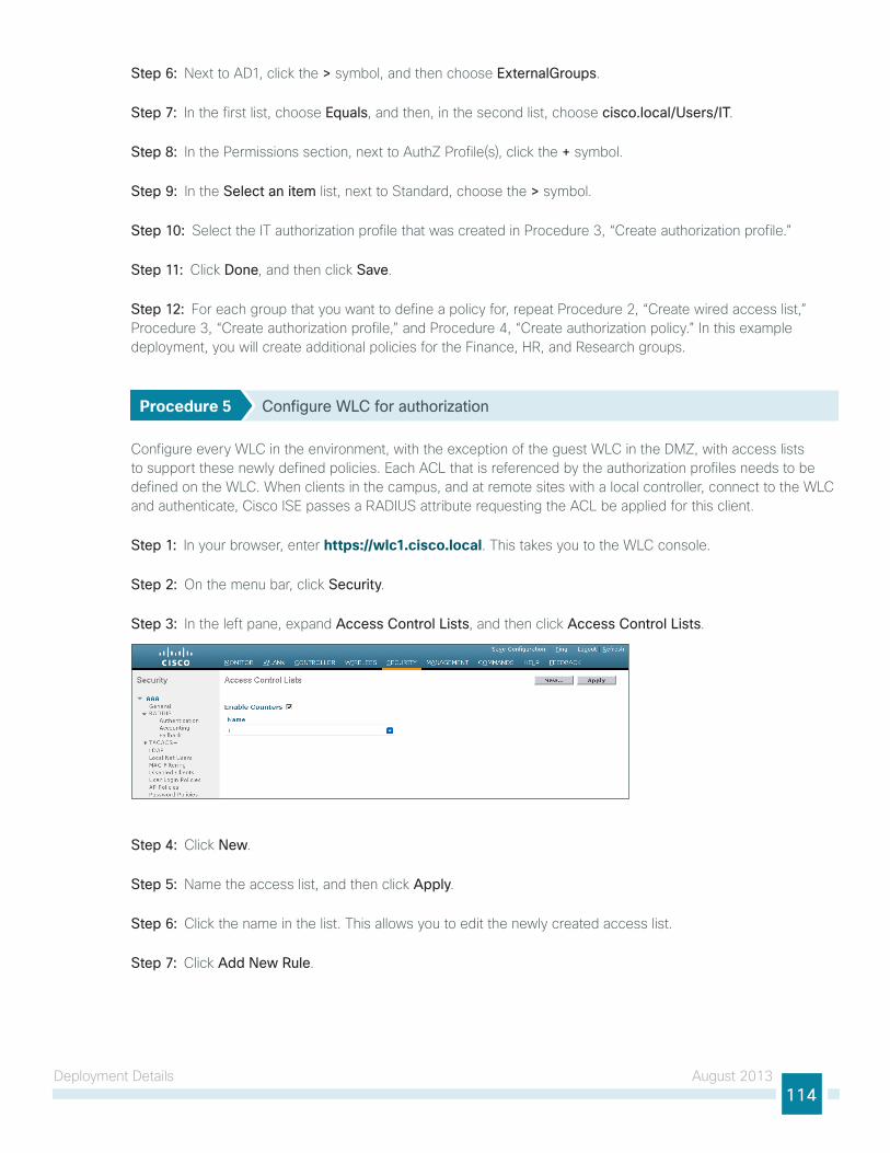
Deployment Details August 2013114
Step 6: next to AD1, click the > symbol, and then choose ExternalGroups.
Step 7: In the first list, choose Equals, and then, in the second list, choose cisco.local/Users/IT.
Step 8: In the Permissions section, next to AuthZ Profile(s), click the + symbol.
Step 9: In the Select an item list, next to Standard, choose the > symbol.
Step 10: Select the It authorization profile that was created in Procedure 3, “Create authorization profile.”
Step 11: Click Done, and then click Save.
Step 12: For each group that you want to define a policy for, repeat Procedure 2, “Create wired access list,” Procedure 3, “Create authorization profile,” and Procedure 4, “Create authorization policy.” In this example deployment, you will create additional policies for the Finance, HR, and Research groups.
Procedure 5 Configure WLC for authorization
Configure every WlC in the environment, with the exception of the guest WlC in the DMZ, with access lists to support these newly defined policies. Each ACl that is referenced by the authorization profiles needs to be defined on the WlC. When clients in the campus, and at remote sites with a local controller, connect to the WlC and authenticate, Cisco ISE passes a RADIuS attribute requesting the ACl be applied for this client.
Step 1: In your browser, enter https://wlc1.cisco.local. this takes you to the WlC console.
Step 2: On the menu bar, click Security.
Step 3: In the left pane, expand Access Control Lists, and then click Access Control Lists.
Step 4: Click New.
Step 5: name the access list, and then click Apply.
Step 6: Click the name in the list. this allows you to edit the newly created access list.
Step 7: Click Add New Rule.

Deployment Details August 2013115
Step 8: Create a new access list rule based on your security policy, and then click Apply. In our example deployment, members of the It group are only allowed access to the internal network (10.4.0.0/16).
the access list needs to have entries for the traffic in both directions, so make sure you have pairs of access list rules for both inbound and outbound traffic. Also, there is an implicit “deny all” rule at the end of the access list so any traffic not explicitly permitted is denied.
Tech Tip
Step 9: Repeat Step 3 through Step 8 in this procedure for each access list that you defined in the authorization profiles in Cisco ISE.
next, you enable WlC in order to allow Cisco ISE to use RADIuS to override the current settings, so that the access list can be applied to the wireless lAn.
Step 10: On the menu bar, click WLANs.
Step 11: Click the WlAn ID of the wireless network that the wireless personal devices are accessing.

Deployment Details August 2013116
Step 12: Click Advanced, and then select Allow AAA Override.
Step 13: Click Apply, and then click Save Configuration.
Enabling Security Group Access
1. Define Security group tags
2. Add ASA as network device
3. Modify authorization policy
4. Configure SXP on IOS devices
5. Configure SXP on WlCs
6. Configure SXP on ASA
7. Configure firewall policy
8. Monitoring Sgts on Cisco ASA
9. Monitoring Sgts on the switches
10. Monitoring Sgts on the WlC
PR
OC
ESS
Security group Access (SgA) technology allows user identity information to be associated with their network traffic and then passed throughout the network. this information can then be used to enforce an access policy using Security group tags (Sgt) and Security group Access Control lists (SgACl).
the Sgt Exchange Protocol (SXP) is used to propagate the IP-to-Sgt bindings across network devices that do not support Sgts. In this example, we are passing Sgt information from the access layer devices to Cisco ASA in the data center.
SXP establishes a peering relationship between two devices to exchange the IP-to-Sgt bindings. there are two roles in the relationship: the speaker and the listener. the speaker passes the IP-to-Sgt bindings to the listener. In our example, the access layer switch needs to pass these bindings to Cisco ASA in the data center. You could have the switch peer directly with the ASA appliance, however, that may not scale well in larger environments. It is a best practice to minimize the number or peers a device has by aggregating connections.

Deployment Details August 2013117
For example, campus access layer switches would peer with a distribution switch, which then would peer with the ASA appliance. Or, access layer switches at a remote site would peer with a distribution switch at the site, which would peer with the WAn aggregation router at the headquarters, which would then peer with the ASA appliance.
22
95
SXPHeadquarters
Data CenterRemote Site
ASA
Wireless LANController
Wireless LANController
DistributionSwitch
DistributionSwitch
WANRouter
AccessSwitches
AccessSwitches
Procedure 1 Define Security Group Tags
Step 1: In a browser, access the primary engine’s guI at http://ise-1.cisco.local.
Step 2: On the menu bar, mouse over Policy, and then in the Policy Elements section, select Results.
Step 3: In the panel on the left, double-click Security Group Access, and then click Security Groups.
Step 4: Click Add.
Step 5: give the group a name and description, and then click Submit.
Step 6: Repeat Step 4 and Step 5 for each tag you wish to create. In this example deployment, you create tags for each of the following groups: Finance_users, HR_users, It_users, Research_users, and network_Devices.
Procedure 2 Add ASA as network device
In order to allow Cisco ISE to provide Sgt enforcement on Cisco ASA, the ASA appliance needs to be added as a network device in ISE.
Step 1: On the menu bar, mouse over Administration, and then in the network Resources section, click Network Devices.
Step 2: Click Add.
Step 3: Enter the hostname of the ASA appliance and give it a description.
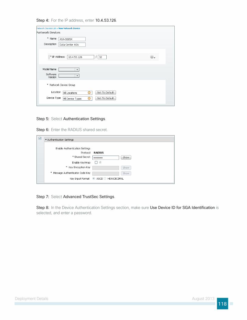
Deployment Details August 2013118
Step 4: For the IP address, enter 10.4.53.126.
Step 5: Select Authentication Settings.
Step 6: Enter the RADIuS shared secret.
Step 7: Select Advanced TrustSec Settings.
Step 8: In the Device Authentication Settings section, make sure Use Device ID for SGA Identification is selected, and enter a password.

Deployment Details August 2013119
Step 9: In the SgA notifications and updates section, accept the default values.
Step 10: In the Out of Band (OOB) SgA PAC section, click Generate PAC.
Step 11: Enter an encryption key and the PAC time to live, and then click Generate PAC.
Step 12: You are prompted to save the file to your local machine. Choose a location, and then click OK.
Step 13: Click Submit.
Procedure 3 Modify authorization policy
In Procedure 4, “Create authorization policy,” of the previous section, you created authorization policies that limited network access based on Active Directory group membership by using access lists. In this procedure, you will modify those policies to instead use Sgts.
Step 1: On the menu bar, mouse over Policy, and then click Authorization.
Step 2: For the It rule, click Edit.
Step 3: In the Permissions column, click the + symbol next to It.
Step 4: Click the + symbol to add a new permission.
Step 5: Expand the drop-down menu and click the > symbol next to Security group.
Step 6: Select IT_Users.
Step 7: Click Done, and then click Save.
Step 8: Repeat Step 2 through Step 7 for each policy you need to modify to support Sgts. In this example deployment, you will edit the Finance, HR and Research policies.

Deployment Details August 2013120
Procedure 4 Configure SXP on IOS devices
Step 1: Connect to the Cisco Prime lMS server by browsing to https://lms.cisco.local:1741.
Step 2: Mouse over Configuration, and then, from the tools section, choose NetConfig.
Step 3: In the netConfig Job Browser, click Create.
Step 4: Select Device Based for the netConfig Job type, and then click Go.
Step 5: In the Device Selector, expand All Devices, and then select the devices where you want to enable SXP.
Step 6: In the task Selector, expand All Tasks, select Adhoc, and then click Next.
Step 7: Click Add Instance, and then, in the new window, enter the ClI commands necessary to enable SXP.
cts sxp enable
cts sxp default password <password>cts sxp default source-ip <IP-address-of-switch>cts sxp connection peer <IP-address-of-peer> password default mode local {speaker|listener}
Step 8: Click Applicable Devices, select the switch to which you want to apply this configuration, click Close, choose Config for the command mode, and then click Save.
Step 9: After returning to the Add tasks window, click Next.
Step 10: Fill in a description for the job, and then click Next. the job is submitted for immediate deployment.
Step 11: Click Finish, and then when you receive a notice that the job was submitted successfully, click OK.
Step 12: Repeat this procedure for each IOS device where you need to configure SXP.
Procedure 5 Configure SXP on WLCs
Step 1: navigate to the WlC console by browsing to https://wlc1.cisco.local.
Step 2: On the menu bar, click Security.
Step 3: In the left pane, click TrustSec SXP.
Step 4: In the SXP State pull-down, select Enabled.
Step 5: Enter the default password. this password must match what is configured on the peer.
Step 6: Add a new peer by clicking New.
Step 7: Enter the IP address of the peer, and then click Apply. the SXP Configuration page appears.

Deployment Details August 2013121
Step 8: Click Apply.
Procedure 6 Configure SXP on ASA
You now configure SXP on Cisco ASA and create a policy that limits access to servers in the data center based on the Sgts.
Step 1: In a browser, navigate to the Cisco ASA management console at https://DC-ASA5585X.cisco.local, and then click Run ASDM.
Step 2: navigate to Configuration > Firewall > Identity by TrustSec.
Step 3: Select Enable SGT Exchange Protocol (SXP).
Step 4: For the Default Source field, enter the IP address of the interface of the Cisco ASA appliance used for management.
Step 5: Enter a password, and then verify it.
Step 6: In the Server group Setup section, click Manage.

Deployment Details August 2013122
Step 7: In the Configure AAA Server group window, click Add.
Step 8: In the AAA Server group field, enter ISE-Group.
Step 9: For Accounting Mode, select Simultaneous, and then click OK.
Step 10: In the Selected group section, for Servers, click Add.
Step 11: In the list, choose the firewall interface outside.

Deployment Details August 2013123
Step 12: In the RADIuS Parameters sections, enter the Shared Secret Key, accept the defaults for the remaining parameters, and then click OK.
Step 13: Repeat Step 10 through Step 12 for the secondary Cisco ISE administration node, ise-2.cisco.local.
Step 14: Click OK. the Configure AAA Server groups window closes.
Step 15: Click Import PAC.
Step 16: Click Browse, and then locate the PAC file you saved to your machine in Step 12, Procedure 2, “Add ASA as network device.”
Step 17: Enter the PAC password, and then confirm it. Click Import.

Deployment Details August 2013124
now you will add SXP peers to Cisco ASA.
Step 18: Click Add.
Step 19: Enter the IP address of the peer.
Step 20: For Password, choose Default, for Mode, choose Local, and for Role, choose Listener, and then click OK.
Step 21: Repeat Step 18 through Step 20 for each peer you need to add.
Step 22: Click Apply.
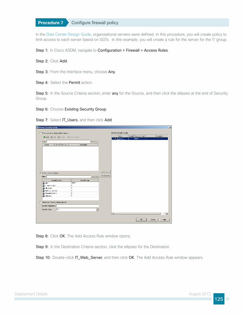
Deployment Details August 2013125
Procedure 7 Configure firewall policy
In the Data Center Design guide, organizational servers were defined. In this procedure, you will create policy to limit access to each server based on Sgts. In this example, you will create a rule for the server for the It group.
Step 1: In Cisco ASDM, navigate to Configuration > Firewall > Access Rules.
Step 2: Click Add.
Step 3: From the Interface menu, choose Any.
Step 4: Select the Permit action.
Step 5: In the Source Criteria section, enter any for the Source, and then click the ellipses at the end of Security group.
Step 6: Choose Existing Security Group.
Step 7: Select IT_Users, and then click Add.
Step 8: Click OK. the Add Access Rule window opens.
Step 9: In the Destination Criteria section, click the ellipses for the Destination.
Step 10: Double-click IT_Web_Server, and then click OK. the Add Access Rule window appears.

Deployment Details August 2013126
Step 11: For the service, enter tcp/http, tcp/https, and then click OK.
Repeat Step 2 through Step 11 for each server that you wish to create an Sgt policy for. In this deployment, the remaining groups are Finance, HR, and Research.
Procedure 8 Monitoring SGTs on Cisco ASA
You will use ASDM to verify SXP is working properly and Sgts are being passed to Cisco ASA.
Step 1: In Cisco ASDM, navigate to Monitoring > Properties > Identity by TrustSec > SXP Connections. this shows all the current SXP connections to the ASA.

Deployment Details August 2013127
Step 2: In Cisco ASDM, navigate to Monitoring > Properties > Identity by TrustSec > IP Mappings. this shows all the current IP to Sgt mappings passed to the ASA.
Procedure 9 Monitoring SGTs on the switches
From the command line of the switch, you monitor SXP connections and the Sgt assignments using a few show commands.
Step 1: Verify the Sgt assigned to a switch port after user authorization on an access layer switch.
show authentication session interface <interface>
A3750X#show authentication session interface GigabitEthernet 2/0/1 Interface: GigabitEthernet2/0/1
MAC Address: 0050.56b9.007c
IP Address: 10.4.2.13
User-Name: alex.reed
Status: Authz Success
Domain: DATA
Security Policy: Should Secure
Security Status: Unsecure
Oper host mode: multi-auth
Oper control dir: both
Authorized By: Authentication Server
Vlan Policy: N/A
SGT: 0004-0
Session timeout: N/A
Idle timeout: N/A
Common Session ID: 0A040F06000001778A321722
Acct Session ID: 0x00000B5D
Handle: 0xCB000178

Deployment Details August 2013128
Step 2: Verify the SXP connections on a switch.
show cts sxp connections
D6500VSS#show cts sxp connections SXP : Enabled
Highest Version Supported: 3
Default Password : Set
Default Source IP: 10.4.15.254
Connection retry open period: 120 secs
Reconcile period: 120 secs
Retry open timer is not running
----------------------------------------------
Peer IP : 10.4.15.5
Source IP : 10.4.15.254
Conn status : On
Conn version : 2
Local mode : SXP Listener
Connection inst# : 4
TCP conn fd : 3
TCP conn password: default SXP password
Duration since last state change: 11:20:31:22 (dd:hr:mm:sec)
----------------------------------------------
Peer IP : 10.4.15.6
Source IP : 10.4.15.254
Conn status : On
Conn version : 3
Local mode : SXP Listener
Connection inst# : 6
TCP conn fd : 1
TCP conn password: default SXP password
Duration since last state change: 11:20:31:22 (dd:hr:mm:sec)
----------------------------------------------
Peer IP : 10.4.53.126
Source IP : 10.4.15.254
Conn status : On
Conn version : 2
Local mode : SXP Speaker
Connection inst# : 1
TCP conn fd : 2
TCP conn password: default SXP password
Duration since last state change: 11:20:31:22 (dd:hr:mm:sec)
----------------------------------------------

Deployment Details August 2013129
Peer IP : 10.4.79.5
Source IP : 10.4.15.254
Conn status : On
Conn version : 3
Local mode : SXP Listener
Connection inst# : 1
TCP conn fd : 4
TCP conn password: default SXP password
Duration since last state change: 11:20:23:02 (dd:hr:mm:sec)
Total num of SXP Connections = 4
Procedure 10 Monitoring SGTs on the WLC
You use the guI of the WlC to monitor the Sgt assignments and SXP connections.
First, verify the Sgt assigned to a client after user authorization on a WlC.
Step 1: In the web console, click Monitor, and then click Clients.
Step 2: Click the client MAC address. the Details window opens.
Step 3: Scroll down to the Security Information section.
next, verify SXP connections from the WlC.
Step 4: In the web console, click Security.

Deployment Details August 2013130
Step 5: In the navigation pane on the left, click TrustSec SXP.
Monitoring Network Access
1. View the Cisco ISE dashboard
2. Configure identity groups
3. Add a custom profile
4. Examining the authentication log
5. Create custom authentication reports
6. Identify endpoints
7. Create device-type reports
PR
OC
ESS
the configuration of the network infrastructure is complete. now it’s time to answer the what, when, where, and who questions regarding network access by using the reporting functionality of Cisco ISE to gain a better understanding of current activity on the network.
Cisco ISE is now configured to authenticate users and to profile endpoints based on RADIuS and DHCP information. the reporting capabilities of Cisco ISE allow you to determine what type of device is connecting to your network, when it connects, and where it connects from. Also, you will know who is connecting to your network and what authentication method was used.
Procedure 1 View the Cisco ISE dashboard
the first place to view this information is on the Cisco ISE home dashboard. It gives a summary view of the health status of the servers in the group, how devices are authenticating, and what types of devices have been profiled.
Step 1: On the menu bar, click Home.

Deployment Details August 2013131
Step 2: If you want to view additional information for a section, click the upper-right corner of that section. the section expands.
Procedure 2 Configure identity groups
Cisco ISE has more in-depth reporting options to give more details on the devices connecting to the network. to help identify the endpoints, you can use identity groups to classify profiled endpoints and to generate reports.
the example below describes how to do this for an Apple iPad. the procedure for other types of devices is similar.
Step 1: In the menu bar, mouse over Policy, and then choose Profiling.
Step 2: Click Apple-iPad. this enables you to edit this policy.
Step 3: Select Create Matching Identity Group, and then click Save.

Deployment Details August 2013132
You can repeat these steps for other endpoint types as needed. You can also investigate the rules used to profile the endpoint to understand the process. In the case of the Apple iPad, Cisco ISE uses two rules. One is based on DHCP information, and the other is based on HttP.
Procedure 3 Add a custom profile
Although there are many pre-defined profiles, you may find that a device you want to profile doesn’t have an existing profile. You can create a new one using unique characteristics of the device. Review some of the existing profiles to get an idea of the options and methods available to you for device profiling.
the example below creates a profile for the Amazon Kindle Fire by using information obtained from the device’s DHCP request and from HttP requests.
Step 1: Connect to https://ise-1.cisco.local.
Step 2: Mouse over Policy, and then, from the drop-down menu, choose Profiling.
Step 3: Click Add.
Step 4: give the policy the name Kindle-Fire and a description.
Step 5: In the rules section, next to Conditions, click the + symbol, and then click Create New Condition (Advance Option).
Step 6: In the Expression list, next to DHCP, click the > symbol, and then choose host-name.
Step 7: In the second list, choose CONTAINS, and then, in the final box, enter kindle.
Step 8: Choose Certainty Factor Increases, and then set the value to 10.

Deployment Details August 2013133
Step 9: Click the gear icon at the end of the rule, and then select Insert new rule below.
Step 10: next to Conditions, click the + symbol, and then click Create New Condition (Advance Option).
Step 11: In the Expression list, next to IP, click the > symbol, and then choose User-Agent.
Step 12: In the second list, choose CONTAINS, and then, in the final box, enter kindle.
Step 13: Choose Certainty Factor Increases, set the value to 20, and then click Submit.
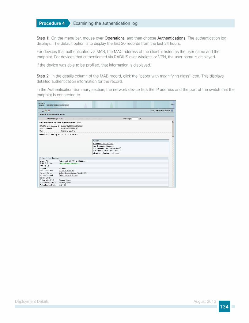
Deployment Details August 2013134
Procedure 4 Examining the authentication log
Step 1: On the menu bar, mouse over Operations, and then choose Authentications. the authentication log displays. the default option is to display the last 20 records from the last 24 hours.
For devices that authenticated via MAB, the MAC address of the client is listed as the user name and the endpoint. For devices that authenticated via RADIuS over wireless or VPn, the user name is displayed.
If the device was able to be profiled, that information is displayed.
Step 2: In the details column of the MAB record, click the “paper with magnifying glass” icon. this displays detailed authentication information for the record.
In the Authentication Summary section, the network device lists the IP address and the port of the switch that the endpoint is connected to.

Deployment Details August 2013135
You can find additional details, such as the Identity group and Identity Policy, in the Authentication Details section.
Similar data can be found for endpoints that have authenticated with RADIuS. the user name is displayed in these records as well as the Extensible Authentication Protocol (EAP) method used.
Procedure 5 Create custom authentication reports
the default authentication log view is limited to displaying only the most recent entries. to get in-depth reporting, you need to create a custom report.
Step 1: On the menu bar, mouse over Operations, and then, in the Reports section, choose Catalog.
Step 2: In the left pane, select AAA Protocol.
Step 3: Select RADIUS Authentication.
Step 4: Click Run. Different time ranges for producing the default report are displayed.
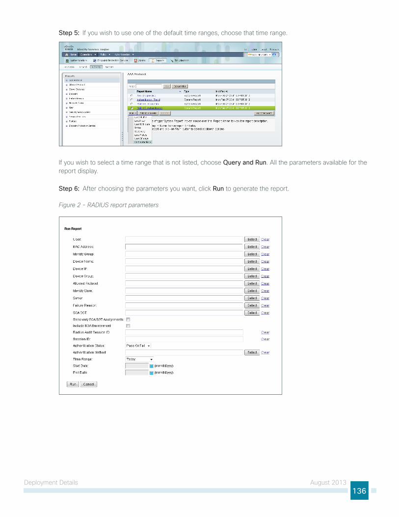
Deployment Details August 2013136
Step 5: If you wish to use one of the default time ranges, choose that time range.
If you wish to select a time range that is not listed, choose Query and Run. All the parameters available for the report display.
Step 6: After choosing the parameters you want, click Run to generate the report.
Figure 2 - RADIUS report parameters

Deployment Details August 2013137
Procedure 6 Identify endpoints
using information gleaned from the RADIuS and DHCP requests, Cisco ISE can identify what types of devices are connecting to the network. this can assist in determining the network security policy based on the type of device that is in use.
Step 1: On the menu bar, mouse over Operations, and then, in the Reports section, choose Catalog.
Step 2: In the left pane, click Endpoint. this displays the available endpoint reports.
Step 3: Select Endpoint Profiler Summary, and then click Run.
Step 4: Select the desired time period to run the report.
Step 5: Once the report is generated, you can view the details of a profiled endpoint by clicking the magnifying glass icon.
the details given in the summary section are the MAC address, the endpoint policy, and the identity group for the endpoint. Additional details, such as IP address and network access devices, are available in the Endpoint Details section. For wireless and remote-access VPn endpoints that authenticated with RADIuS, the user name is also listed.
Figure 3 - Endpoint profile summary
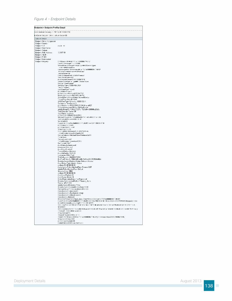
Deployment Details August 2013138
Figure 4 - Endpoint Details
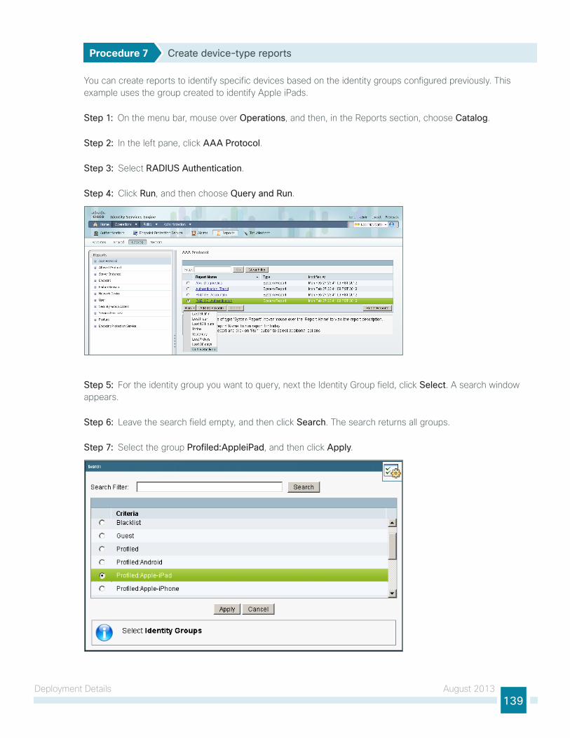
Deployment Details August 2013139
Procedure 7 Create device-type reports
You can create reports to identify specific devices based on the identity groups configured previously. this example uses the group created to identify Apple iPads.
Step 1: On the menu bar, mouse over Operations, and then, in the Reports section, choose Catalog.
Step 2: In the left pane, click AAA Protocol.
Step 3: Select RADIUS Authentication.
Step 4: Click Run, and then choose Query and Run.
Step 5: For the identity group you want to query, next the Identity group field, click Select. A search window appears.
Step 6: leave the search field empty, and then click Search. the search returns all groups.
Step 7: Select the group Profiled:AppleiPad, and then click Apply.

Deployment Details August 2013140
Step 8: Select a time range for the report, and then click Run. the report generates.
Figure 5 - Sample report

Appendix A: Product list August 2013141
Appendix A: Product listNetwork Management
Functional Area Product Description Part Numbers Software
Identity Management
Cisco Identity Services Engine Virtual Appliance ISE-VM-K9= 1.1.2.145
Cisco ISE Base License for 2500 Endpoints L-ISE-BSE-2500=
Cisco ISE Base License for 3500 Endpoints L-ISE-BSE-3500=
Cisco ISE Base License for 5000 Endpoints L-ISE-BSE-5K=
Cisco ISE Base License for 10,000 Endpoints L-ISE-BSE-10K=
Cisco ISE Advanced 3-year License for 2500 Endpoints L-ISE-ADV3Y-2500=
Cisco ISE Advanced 3-year License for 3500 Endpoints L-ISE-ADV3Y-3500=
Cisco ISE Advanced 3-year License for 5000 Endpoints L-ISE-ADV3Y-5K=
Cisco ISE Advanced 3-year License for 10,000 Endpoints L-ISE-ADV3Y-10K=
Network Management
Cisco Prime Infrastructure 1.1 R-PI-1.1-K9 4.2
Prime Infrastructure 1.1 Software – 50 Device Base License R-PI-1.1-50-K9
Prime Infrastructure 1.1 Software – 100 Device Base License R-PI-1.1-100-K9
Prime Infrastructure 1.1 Software – 500 Device Base License R-PI-1.1-500-K9
Prime Infrastructure 1.1 Software – 1K Device Base License R-PI-1.1-1K-K9
Prime Infrastructure 1.1 Software – 2.5K Device Base License R-PI-1.1-2.5K-K9
Prime Infrastructure 1.1 Software – 5K Device Base License R-PI-1.1-5K-K9
LAN Access LayerFunctional Area Product Description Part Numbers Software
Modular Access Layer Switch
Cisco Catalyst 4507R+E 7-slot Chassis with 48Gbps per slot WS-C4507R+E 3.4.0.SG(15.1-2SG) IP Base licenseCisco Catalyst 4500 E-Series Supervisor Engine 7L-E WS-X45-SUP7L-E
Cisco Catalyst 4500 E-Series 48 Ethernet 10/100/1000 (RJ45) PoE+ ports WS-X4648-RJ45V+E
Cisco Catalyst 4500 E-Series 48 Ethernet 10/100/1000 (RJ45) PoE+,UPoE ports
WS-X4748-UPOE+E
Stackable Access Layer Switch
Cisco Catalyst 3850 Series Stackable 48 Ethernet 10/100/1000 PoE+ ports WS-C3850-48F 3.2.1SE(15.0-1EX1) IP Base licenseCisco Catalyst 3850 Series Stackable 24 Ethernet 10/100/1000 PoE+ Ports WS-C3850-24P
Cisco Catalyst 3850 Series 2 x 10GE Network Module C3850-NM-2-10G
Cisco Catalyst 3850 Series 4 x 1GE Network Module C3850-NM-4-1G
Cisco Catalyst 3750-X Series Stackable 48 Ethernet 10/100/1000 PoE+ ports WS-C3750X-48PF-S 15.0(2)SE2 IP Base licenseCisco Catalyst 3750-X Series Stackable 24 Ethernet 10/100/1000 PoE+ ports WS-C3750X-24P-S
Cisco Catalyst 3750-X Series Two 10GbE SFP+ and Two GbE SFP ports network module
C3KX-NM-10G
Cisco Catalyst 3750-X Series Four GbE SFP ports network module C3KX-NM-1G

Appendix A: Product list August 2013142
Functional Area Product Description Part Numbers Software
Standalone Access Layer Switch
Cisco Catalyst 3560-X Series Standalone 48 Ethernet 10/100/1000 PoE+ ports
WS-C3560X-48PF-S 15.0(2)SE2 IP Base license
Cisco Catalyst 3560-X Series Standalone 24 Ethernet 10/100/1000 PoE+ ports
WS-C3560X-24P-S
Cisco Catalyst 3750-X Series Two 10GbE SFP+ and Two GbE SFP ports network module
C3KX-NM-10G
Cisco Catalyst 3750-X Series Four GbE SFP ports network module C3KX-NM-1G
Stackable Access Layer Switch
Cisco Catalyst 2960-S Series 48 Ethernet 10/100/1000 PoE+ ports and Two 10GbE SFP+ Uplink ports
WS-C2960S-48FPD-L 15.0(2)SE2 LAN Base license
Cisco Catalyst 2960-S Series 48 Ethernet 10/100/1000 PoE+ ports and Four GbE SFP Uplink ports
WS-C2960S-48FPS-L
Cisco Catalyst 2960-S Series 24 Ethernet 10/100/1000 PoE+ ports and Two 10GbE SFP+ Uplink ports
WS-C2960S-24PD-L
Cisco Catalyst 2960-S Series 24 Ethernet 10/100/1000 PoE+ ports and Four GbE SFP Uplink ports
WS-C2960S-24PS-L
Cisco Catalyst 2960-S Series Flexstack Stack Module C2960S-STACK
Wireless LAN ControllersFunctional Area Product Description Part Numbers Software
On Site, Remote Site, or Guest Controller
Cisco 5500 Series Wireless Controller for up to 500 Cisco access points AIR-CT5508-500-K9 7.4.100.0
Cisco 5500 Series Wireless Controller for up to 250 Cisco access points AIR-CT5508-250-K9
Cisco 5500 Series Wireless Controller for up to 100 Cisco access points AIR-CT5508-100-K9
Cisco 5500 Series Wireless Controller for up to 50 Cisco access points AIR-CT5508-50-K9
Cisco 5500 Series Wireless Controller for up to 25 Cisco access points AIR-CT5508-25-K9
Cisco 5500 Series Wireless Controller for up to 12 Cisco access points AIR-CT5508-12-K9
Cisco 5500 Series Wireless Controller for High Availability AIR-CT5508-HA-K9
On Site Controller, Guest Controller
Cisco 2500 Series Wireless Controller for up to 50 Cisco access points AIR-CT2504-50-K9 7.4.100.0
Cisco 2500 Series Wireless Controller for up to 25 Cisco access points AIR-CT2504-25-K9
Cisco 2500 Series Wireless Controller for up to 15 Cisco access points AIR-CT2504-15-K9
Cisco 2500 Series Wireless Controller for up to 5 Cisco access points AIR-CT2504-5-K9

Appendix A: Product list August 2013143
Wireless LAN Access PointsFunctional Area Product Description Part Numbers Software
Wireless Access Points
Cisco 3600 Series Access Point Dual Band 802.11a/g/n and CleanAir with Internal Antennas
AIR-CAP3602I-x-K9 7.4.100.0
Cisco 3600 Series Access Point Dual Band 802.11a/g/n and CleanAir with External Antennas
AIR-CAP3602E-x-K9
Cisco 2600 Series Access Point Dual Band 802.11a/g/n and CleanAir with Internal Antennas
AIR-CAP2602I-x-K9
Cisco 2600 Series Access Point Dual Band 802.11a/g/n and CleanAir with External Antennas
AIR-CAP2602E-x-K9
Cisco 1600 Series Access Point Dual-band controller-based 802.11a/g/n with Internal Antennas
AIR-CAP1602I-x-K9
Cisco 1600 Series Access Point Dual-band controller-based 802.11a/g/n with External Antennas
AIR-CAP1602E-x-K9
Data Center ServicesFunctional Area Product Description Part Numbers Software
Firewall Cisco ASA 5585-X Security Plus IPS Edition SSP-10 and IPS SSP-10 bundle ASA5585-S10P10XK9 ASA 9.0(1) IPS 7.1(7) E4Cisco ASA 5585-X Security Plus IPS Edition SSP-20 and IPS SSP-20 bundle ASA5585-S20P20X-K9
Cisco ASA 5585-X Security Plus IPS Edition SSP-40 and IPS SSP-40 bundle ASA5585-S40P40-K9

Americas HeadquartersCisco Systems, Inc.San Jose, CA
Asia Pacific HeadquartersCisco Systems (USA) Pte. Ltd.Singapore
Europe HeadquartersCisco Systems International BV Amsterdam,The Netherlands
Cisco has more than 200 offices worldwide. Addresses, phone numbers, and fax numbers are listed on the Cisco Website at www.cisco.com/go/offices.
ALL DESIGNS, SPECIFICATIONS, STATEMENTS, INFORMATION, AND RECOMMENDATIONS (COLLECTIVELY, “DESIGNS”) IN THIS MANUAL ARE PRESENTED “AS IS,” WITH ALL FAULTS. CISCO AND ITS SUPPLIERS DISCLAIM ALL WARRANTIES, INCLUDING, WITHOUT LIMITATION, THE WARRANTY OF MERCHANTABILITY, FITNESS FOR A PARTICULAR PURPOSE AND NONINFRINGEMENT OR ARISING FROM A COURSE OF DEALING, USAGE, OR TRADE PRACTICE. IN NO EVENT SHALL CISCO OR ITS SUPPLIERS BE LIABLE FOR ANY INDIRECT, SPECIAL, CONSEQUENTIAL, OR INCIDENTAL DAMAGES, INCLUDING, WITHOUT LIMITATION, LOST PROFITS OR LOSS OR DAMAGE TO DATA ARISING OUT OF THE USE OR INABILITY TO USE THE DESIGNS, EVEN IF CISCO OR ITS SUPPLIERS HAVE BEEN ADVISED OF THE POSSIBILITY OF SUCH DAMAGES. THE DESIGNS ARE SUBJECT TO CHANGE WITHOUT NOTICE. USERS ARE SOLELY RESPONSIBLE FOR THEIR APPLICATION OF THE DESIGNS. THE DESIGNS DO NOT CONSTITUTE THE TECHNICAL OR OTHER PROFESSIONAL ADVICE OF CISCO, ITS SUPPLIERS OR PARTNERS. USERS SHOULD CONSULT THEIR OWN TECHNICAL ADVISORS BEFORE IMPLEMENTING THE DESIGNS. RESULTS MAY VARY DEPENDING ON FACTORS NOT TESTED BY CISCO.
Any Internet Protocol (IP) addresses used in this document are not intended to be actual addresses. Any examples, command display output, and figures included in the document are shown for illustrative purposes only. Any use of actual IP addresses in illustrative content is unintentional and coincidental.
© 2013 Cisco Systems, Inc. All rights reserved.
Cisco and the Cisco logo are trademarks or registered trademarks of Cisco and/or its affiliates in the U.S. and other countries. To view a list of Cisco trademarks, go to this URL: www.cisco.com/go/trademarks. Third-party trademarks mentioned are the property of their respective owners. The use of the word partner does not imply a partnership relationship between Cisco and any other company. (1110R)
Please use the feedback form to send comments and suggestions about this guide.
Feedback
B-0000138-1 08/13


![BYOD Guide Created using iThoughts [...] [...]. BYOD Guide.](https://static.documents.pub/doc/80x56/56649c935503460f9494f988/byod-guide-created-using-ithoughts-byod-guide.jpg)


