The Piping Profile in general can be considered as a complex and rigid piping network consisting of variouspiping components, which have different diameters and weights. At the same time the above network is alsosubjected to temperature change while switching from installed to operating condition (and visa versa)resulting into its thermal growth in various directions in proportion to the length of pipes. The structuralintegrity of the above network must therefore take into account the overall weight effect of the profilebesides its thermal growth.
A satisfactory design of the Piping System should therefore give a careful consideration to achieve the aboverequirement. This is generally accomplished by providing external attachments (known as pipe supports) atvarious locations of the piping profile.
This document deals with the basic purpose of the pipe supports, classification based on construction /functions and a few typical types of pipe supports.
In general it deals with metallic piping systems only.
2.0 PURPOSE OF PIPE SUPPORTS
A brief detail of the purpose of pipe support is described below.
2.1 TO SUPPORT WEIGHT OF PIPE-DURING OPERATION & TESTING
Supports are required to support the line during all conditions i.e. during operation as well as during testing.In case of vapour line this difference will be very large due to hydro testing. Supports should be designedfor this load (unless otherwise decided in the project).
Some times line is capable of having longer span but load coming on the support may be very large(especially with large dia pipe lines). Then to distribute the load uniformly, more number of supports shouldbe provided with smaller span.
Note : 1. It may be noted that during testing condition there is no thermal load.2. All spring supports are locked during testing.
2.2 TO TAKE 'EXPANSION LOAD' :
Whenever thermal expansion is restricted by support, it introduces additional load on the support. Supportmust be designed to take this load in addition to all other loads.
2.3 TO TAKE 'WIND LOAD' :
Wind introduces lateral load on the line. This load is considerable especially on large diameter pipe. Thistends to sway the line from its normal position and line must be supported guided against it. In case of largediameter overhead lines, supported by tall support extended from floor, wind load introduces large bendingmoment and should be considered critically.
2.4 TO TAKE 'EARTH QUAKE LOAD' :
The earthquake is normally associated with horizontal acceleration of the order of 1 to 3 m/sec2. This isaround 10% to 30% of the gravitational acceleration and introduces horizontal force of about 10 to 30% ofthe vertical load (or supported mass). While designing support this should be taken care.
TRAINING MANUAL- PIPING
PIPE SUPPORTS
Uhde India Limited
DOC No. : 29040-PI-UFR-0028
Rev. : R0
Page : 3
2.5 TO ABSORB 'VIBRATION OF PIPING SYSTEM' :
When the pipe is subjected to moving machinery or pulsating flow or very high velocity flow, pipe may startvibrating vigorously and ultimately may fail, particularly if span is large. To avoid this it may be required tointroduce additional supports at smaller span apart from other requirements. It may not take axial load, butmust control lateral movements.
2.6 TO HAVE 'NOISE CONTROL' :
In most of the plants, noise is resulting from vibration and if such vibrations are controlled, noise is reducedto great extent. In such lines, between clamp (i.e. support) and pipe, asbestos cloth is put to absorb vibrationand avoid noise.
Noise due to pulsating flow can be reduced by using a silencer in the line. Still if it is not below acceptablelevel accoustic enclosure may be used. insulation over line also helps in reducing the noise.
2.7 TO TAKE 'HYDRAULIC THRUST IN PIPING' :
The hydraulic thrust in the pipeline is present at certain point such as pressure reducing valve, relief valve,bellows etc.
If the control valve has large pressure differential and line size is more, then this force can be very high.The support should be provided and designed to take this load, otherwise this will load the piping system andmay cause failure.
2.8 TO SUPPORT THE SYSTEM DURING 'TRANSIENT PERIOD OF PLANT AND STANDBYCONDITION :
TRAINING MANUAL- PIPING
PIPE SUPPORTS
Uhde India Limited
DOC No. : 29040-PI-UFR-0028
Rev. : R0
Page : 4
Transient condition refers to the start-up or shutdown condition in which one equipment may get heated upfaster and other one get heated slower. Due to this the expansion of one equipment which in normaloperation will get nullified, may not get nullified and exert thermal load on supports.
Standby condition is also similar. If there are two pumps, one being standby and both connected in parallel(as shown), design and operating temp. of both the connections will be same. But the expansion of twoparallel legs will not be nullified because at a time only one leg will be hot and another being cold.
2.9 TO SUPPORT THE SYSTEM DURING 'MAINTENANCE CONDITIONS' :
When for maintenance certain equipment or component like valve is taken out, remaining system should notbe left out unsupported.
Referring to the FIG-3, support 'S1' will be sufficient but when valve 'V1' is taken out for maintenance therewill not be any support for vertical leg. Therefore second support 'S2' may be required to take care of suchcondition.
2.10 TO SUPPORT THE SYSTEM DURING 'SHUTDOWN CONDITIONS' :
In shutdown condition all equipment may not be in the same condition as in operating condition.For example, refer the pump discharge line in FIG-4, Point A is resting, Point B & C are spring supports
and Point D is the pump discharge nozzle. The springs are, designed based on weights considering theweight of fluid as well as pipeline and thermal movements. But during shutdown condition the fluid may bedrained and the pipe becomes lighter. Hence the spring will give upward reaction and shall load the nozzle'D' beyond permissible limit.
TRAINING MANUAL- PIPING
PIPE SUPPORTS
Uhde India Limited
DOC No. : 29040-PI-UFR-0028
Rev. : R0
Page : 5
In this case a limit stop is used which will not allow the Point C to move up above horizontal level.(However it will allow downward movement during operating condition).
2.11 TO SUPPORT THE SYSTEM FOR ERECTION CONDITIONS :
Erection condition can be different than the operating condition which should be considered while designingsupports.
For example for normal operation a long vessel supported by three supports, S1, S2 & S3 is shown inFIG-5. If support S2 is higher, than all load will act at S2 only. During erection if level of S2 is lower thenentire load will be divided into two supports S1, S2 only. Therefore foundation of S1, S2 & S3 should becapable of taking such conditions.
A pipe line supported by S1, S2 & S3 taken from vessel is shown in above FIG - 6. During operation therewill be no weight at S2 & S3 (as it is only guide), but wind condition will be there. Loads due to suchconditions must be considered while designing the supports.
TRAINING MANUAL- PIPING
PIPE SUPPORTS
Uhde India Limited
DOC No. : 29040-PI-UFR-0028
Rev. : R0
Page : 6
3.0 CLASSIFICATION OF PIPE SUPPORTS
Broadly the pipe supports are classified in three groups as per following details / functions :- General details- Construction details- Functions ie. purpose
These are described below in brief.
3.1 CLASSIFICATION AS PER GENERAL DETAILS :
A pipe line need to be supported from a foundation or an structure. The piping loads will be acting on thesefoundations / structures. Since these foundations / structures are built on ground, they will exert an equal andopposite reaction, while supporting the pipe.
In a pipe support, there will be some parts of support arrangement which is directly attached to the pipelineand there will be some other parts which shall be directly attached to the foundation / structure supportingthe pipe.
As per this general detail the support is classified as :
3.1.1 PRIMARY SUPPORTS :
It is the parts of support assembly which is directly connected to the pipe.
3.1.2 SECONDARY SUPPORTS :
It is the parts of support assembly which is directly connected to the foundation / structure and issupporting the primary support attached to the pipe line.
3.2 CLASSIFICATION AS PER CONSTRUCTION :
Based on construction details, pipe supports are broadly classified in three types, as
This type of support arrangement is generally very simple and has maximum use in piping. It does not haveadjustibility to the erection tolerances. It will directly rest on foundation or structure which is supporting thepipe. Common type of RIGID SUPPORTS are shoe type (welded), shoe type (with clamp) Trunnion type,valve holder type, support brackets (Secondary Support). These are described under the topic 'SupportsGenerally used'.
3.2.2 ELASTIC SUPPORT :
This type of support is commonly used for supporting hot piping. It shall be able to support pipes evenwhen the pipe is moving up or down at support point.
Common type of elastic supports are variable type spring supports, constant type spring supports. These aredescribed under the topic 'Supports generally used '.
TRAINING MANUAL- PIPING
PIPE SUPPORTS
Uhde India Limited
DOC No. : 29040-PI-UFR-0028
Rev. : R0
Page : 7
3.2.3 ADJUSTABLE SUPPORTS :
This type of support is Rigid type in construction but is has few nuts and bolts arrangements for adjusting thesupports with respect to the actual erected condition of pipe. The support can be adjusted for the erectiontolerances in the piping. These are required for a better supporting needs at critical locations of pipesupports.
Mostly all type of rigid supports can be modified by using certain type of nuts and bolts arrangement, tomake it as an Adustable support.
Only a typical type of adjustable support is described under the topic 'Supports Generally used.'
3.3 CLASSIFICATION AS PER FUNCTION (i.e. PURPOSE)
Pipe supports classified as per functions are summarised in the Table at FIG.7. These are shown along withits basic construction, the symbols generally used and type of restraints it offers to the piping system.
TRAINING MANUAL- PIPING
PIPE SUPPORTS
Uhde India Limited
DOC No. : 29040-PI-UFR-0028
Rev. : R0
Page : 8
The supports classified as per function are further described as follows :
3.3.1 LOOSE SUPPORT :
This is most commonly used support meant for supporting only the pipe weight vertically. It allows pipe tomove in axial as well as transverse direction but restricts only the vertical downward movement.
3.3.2 LONGITUDINAL GUIDE :
This type of support is used to restrict the movement of pipe in transverse direction i.e. perpendicular tolength of pipe but allow movement in longitudinal direction. This is also a commonly used type ofsupport. Generally it is used along with Loose support.
3.3.3 TRANSVERSE GUIDE :
This type of support is used to restrict the movement of pipe in longitudinal (axial ) direction but allows thepipe to move in transverse direction. This is also referred as 'AXIAL STOP'. This type is less used ascompared to above two types. Generally it is used along with Loose support.
3.3.4 FIXED POINT / ANCHOR :
FIX POINT type of support is used to restrict movements in all three directions. ANCHOR type of supportis used to restirct movement in all three directions and rotation also in these three directions.
Non-Welded Type (FIX POINT) :
This can be considered as a combination of longitudinal and transverse guide. This type resist only thelinear movements in all directions but not the rotational movements. This avoids heavy loading of support aswell as pipe. Therefore this type of support is preferred over welded type.
Welded Type (ANCHOR)
This type of support prevents total movements i.e. linear as well as rotational. This type of support is usedwhen it is absolutely essential to prevent any moment/force being transferred further. It causes heavyloading on support as well as pipe.
3.3.5 LIMIT STOP :
As name itself indicates it allows pipe movement freely upto a certain limit and restricts any furthermovement. This is useful when total stops causes excessive loading on piping and support or nozzle.
This type of support should be used selectively, because of stringent and complicated requirements ofdesign, erection and operation.
3.3.6 SPECIAL SUPPORTS :
When we need a pipe support whose construction or functional details are different from the availabledetails, then a special support detail sketch is prepared. The functions of this support can be anycombination of above functions.
TRAINING MANUAL- PIPING
PIPE SUPPORTS
Uhde India Limited
DOC No. : 29040-PI-UFR-0028
Rev. : R0
Page : 9
4.0 SUPORT DETAILS GENERALLY USED :
Following are the type of supports generally used in a project.
4.1 SHOE TYPE SUPPORT :
Shoe type support are the supports used maximum in any project. These can be directly welded to pipe orcan be welded to a clamp put around pipe. Shoe type supports are used for supporting lines with insulations.
Basically the detail is as follows :Basically it is used as a Loose support. With slight addition of details it can be also used as a guide, fixpoint, anchor, transverse guide, limit stops. It can also be modified to be used as Adjustable supports.
These are primary supports and will be supported on secondary supports (i.e. Foundation or structure)
4.2 TRUNNION SUPPORTS :
In this type of support, a dummy pipe is welded to the main line so that the dummy pipe becomes a rigid partof the main pipe line. Now this pipe is suitably supported on a secondary support (Foundation or a structure)The basic detail is as follows :
As per piping requirement, the TRUNNIONS can be VERTICLE (as shown in FIG-9) or can also be inHORIZONTAL. These are used for loose supports, guides, transverse guides, fix points, achors as well asadjustable supports.
me
Highlight
me
Highlight
TRAINING MANUAL- PIPING
PIPE SUPPORTS
Uhde India Limited
DOC No. : 29040-PI-UFR-0028
Rev. : R0
Page : 10
4.3 HANGER SUPPORT :As the name suggest, in a hanger suport the pipe is hung from an structure using a hanger rod.
As is clear from the FIG.-10, pipe can move in all direction except downwards. A hanger support generallyuses a clamp on the pipe. When a turn buckle is used than the support is adjustable type.
Hanger rods are used as a loose supports, which is free to lift up.
4.4 VALVE HOLDERS :
Valve Holder is special type of support, which is used in the situations where it is intended to directlysupport the valve body through its flanges. It is an assembly of 2 holder plates bolted to the end flanges ofthe valve to be supported. These holder plates are in turn connected (bolted) to a common base plate tocomplete the valve holder assembly.
This support is relatively expensive since it involves many fabrication steps (e.g. machining / drilling ofholder plates etc.) The above support is therefore used only in the situations where it is absolutely necessaryto directly support the valve body owing the weak pipe material (e.g. Plastic Piping) which is incapable of
me
Highlight
TRAINING MANUAL- PIPING
PIPE SUPPORTS
Uhde India Limited
DOC No. : 29040-PI-UFR-0028
Rev. : R0
Page : 11
transferring the valve load the support through the pipe section. The above support is therefore not calledfor, in case of Carbon Steel Piping.
This support is generally used on loose suport, guide support and fixpoint. Other functions are less common.
4.5 SPRING SUPPORT :
Spring Support is a special type of support which is used in the situations where the support point on the pipeis expected to move up or down during the operating condition (due to thermal growth ) from its installedposition without spring, the pipe will therefore either lift from secondary support or will make anunsuccessful attempt to press against the rigid secondary support. Both are detrimental to the structuralintegrity of the Piping System.
The spring support basically employs a spring element, which can get compressed or open up dependingupon the thermal movement at the support point of pipe. By doing so it takes the vertical load of the pipingunder both the situations. From the utility point, spring supports are classified as Variable spring type &constant spring type. As per arrangement spring support can be classified as supporting the pipe from under(i.e resting type) or as supporting the pipe from above (i.e. hanger type).
4.5.1 VARIABLE SPRING SUPPORT :
This basically consists of spring which can get compressed or expanded according to thermal expansion.However this movement causes increase or decrease in supporting force depending on its stiffness and thisdifferential load is transferred to the pipe, but this is much less than that would be with rigid support or rigidhanger.
Variable spring supports are further classified as 'HANGER TYPE' and bottom support type as described atpara 4.5.3 & 4.5.4.
4.5.2 CONSTANT SPRING SUPPORTS :
In variable spring support variability factor is maintained generally within 25%. When the verticalmovement of support point is large and/or a very less magnitude of differential force from cold to hotcondition is permissible, then constant type of support is used. This is also basically spring support but loadis supported by it through a lever mechanism in such a way that when spring gets compressed effectiveleverage is reduced and vice-versa. So that net supporting force remains constant, i.e. without any loadfluctuation.
Like variable spring supports, these are also available as Hanger type and bottom support types.
4.5.3 HANGER TYPE (VARIABLE)In hanger type variable spring support, the pipe is hung from the secondary support using hanger type spring,as shown.
TRAINING MANUAL- PIPING
PIPE SUPPORTS
Uhde India Limited
DOC No. : 29040-PI-UFR-0028
Rev. : R0
Page : 12
4.5.4 BOTTOM SUPPORT TYPE (VARIABLE)
In bottom support type variable spring, the pipe is resting on top of the spring load plate, as shown.
The selection is based on the availability of structure.
In these two types manufacturer offers various models suitable for different types of attachment. These arebetter described / shown in manufacturers catalogue viz. SARATHI & UMA whose catalogue for all theabove are available with us.
Note :
From all the above description it may create the impression that constant spring supports are better thanvariable spring supports, however it is not so. The reasons are : -
- constant support is costlier than the variable spring supports.- constant spring support cannot adjust itself to actual variation in load.
4.6 ADJUSTABLE SUPPORT :
As the name suggest, this type of support is capable of adjustment at site to accommodate erection tolerancesof piping. Basically all type of support can be easily modified and made adjustable. A typical example forsupport at pump suction is shown below.
These type of supports are generally used as Loose support.
TRAINING MANUAL- PIPING
PIPE SUPPORTS
Uhde India Limited
DOC No. : 29040-PI-UFR-0028
Rev. : R0
Page : 13
4.7 U-BOLT TYPE SUPPORT :
U-bolt type support is one of the most simplest and extensively used primary support item for supporting un-insulated piping.
These are generally used as GUIDES. These can be used conveniently as fix points for smaller size, non-insulated piping. For large dia pipes, its use as fix point is generally avoided.
4.8 SUPPORT BRACKETS :
These are basically the secondary supports. All supports discussed before this has been primary supports.
The support brackets are structural frames used in between the primary supports and the building structure.The support brackets are fixed to the building structure or foundations. These are required at places wherethe pipe can not be directly supported from a building structure or any foundation.
The members used for brackets are structural items like beams, channels, angles, plates etc.
Some of the basic guide lines for design of secondary supports (Brackets) are discussed below.
5.0 SECONDARY SUPPORT DESIGN CONSIDERATION :
Although the design basis of a secondary supports (Brackets) is purely an structural design, but since thepiping loads are not purely static and many times, a large cantilever structures are required, it needs certainspecial considerations in its design as follows :
5.1 Supporting should not be done at any location for individual lines. The support details should be madekeeping in view all the lines requiring supports at any particular location.
(In all the Figures to follow, member details shown as (-x-x-x) shall indicate suggested modification ).
Instead of supporting structures No.1, 2, & 3; one support sketch should be provided; it shall make thearrangement compact and strong.
me
Highlight
me
Highlight
TRAINING MANUAL- PIPING
PIPE SUPPORTS
Uhde India Limited
DOC No. : 29040-PI-UFR-0028
Rev. : R0
Page : 14
5.2 L-type support should be avoided as far as possible. It should be used only when 'H' as well as 'L'dimensions are comparatively less and the suitability of the structure is properly seen.
As an example we should avoid support details as given in this figure above.
• We should also avoid unnecessary extra projections when L=dimen. is becoming large.
When L-dim. is becoming large we should try to connect the loose end 'X' to some near by structure or elseincrease the member size and connection detail at insert plate 'I'.
TRAINING MANUAL- PIPING
PIPE SUPPORTS
Uhde India Limited
DOC No. : 29040-PI-UFR-0028
Rev. : R0
Page : 15
Some of the suggested detail for the above support requirement are given below :
The option given below should be the last option since it requires more work and the configuration looksodd due to larger member size.
As far as possible we should use support details which are connected both ends, no matter, even if thedim.L' is as low as 350 mm.
5.3 T-Type supports whenever erected on beams, a good connection detail should be specified. Few examplesof connections details are mentioned here.
5.4 While supporting hot pipes, we must provide structure sizes sufficiently large so as to accommodate themovement of pipes on the support structure.
TRAINING MANUAL- PIPING
PIPE SUPPORTS
Uhde India Limited
DOC No. : 29040-PI-UFR-0028
Rev. : R0
Page : 16
* In any case these lengths should not be less than 200mm. More than this, pipe movements due to thermalexpansion, wind, earthquake should be seen.
Whenever such type of small T-Post structure is there we must try to connect it to the near by structure.This costs hardly anything but improves the structure support design.
5.5 It is normally noted that the structures are adequately designed for weight of the piping systems but in mostof the cases horizontal loads due to friction is over looked. These horizontal loads can be around 25 to 35%of the vertical loads.
Therefore horizontal loads should be properly considered during the design of support structure.
Whenever these horizontal forces due to friction becomes so large that the system is not able to withstandthen we should provide a suitable means to reduce this friction. Some of the suitable means are as follows :
5.5.1 Provide roller support or Ball bearing supports.
5.5.2 Provide Grafoil sheets between pipe shoe and support structure. Similarly teflon sheets can beprovided.
TRAINING MANUAL- PIPING
PIPE SUPPORTS
Uhde India Limited
DOC No. : 29040-PI-UFR-0028
Rev. : R0
Page : 17
6.0 SPECIAL SUPPORTING CASES :
Few special supporting cases near pumps, tall vessels and exchangers are described as follows :
6.1 Case - 1 :
To avoid loading of suction nozzle due to control valve weight, which is nearby, if we provide a trunnion(non insulated as per normal practice) to take weight of control valve, then during operation such nozzle willmove up and lift the trunnion off its base. This will load the nozzle and purpose of trunnion will not getserved.
This can be avoided by insulating trunnion, so that it will remain hot and will expand upwards and willprovide resting. Thus in most cases, the nozzle loading can be controlled without use of spring supports, nearpump nozzles.
TRAINING MANUAL- PIPING
PIPE SUPPORTS
Uhde India Limited
DOC No. : 29040-PI-UFR-0028
Rev. : R0
Page : 18
6.2 Case - 2 :
When supporting a line coming from top nozzle of a short vessel as shown in FIG-22, if the temperature andmaterial of the vessel and pipe line is same, then the line may be supported at ground level.
6.3 Case - 3 :
When supporting a line coming from a tall vessel and the line temperature is different from vessel, it shouldbe supported from vessel at the neutral point with respect to vessel. Such point is normally near the nozzleitself (FIG-23). The pump should be connected through flexible loop connection to avoid nozzle loading.
TRAINING MANUAL- PIPING
PIPE SUPPORTS
Uhde India Limited
DOC No. : 29040-PI-UFR-0028
Rev. : R0
Page : 19
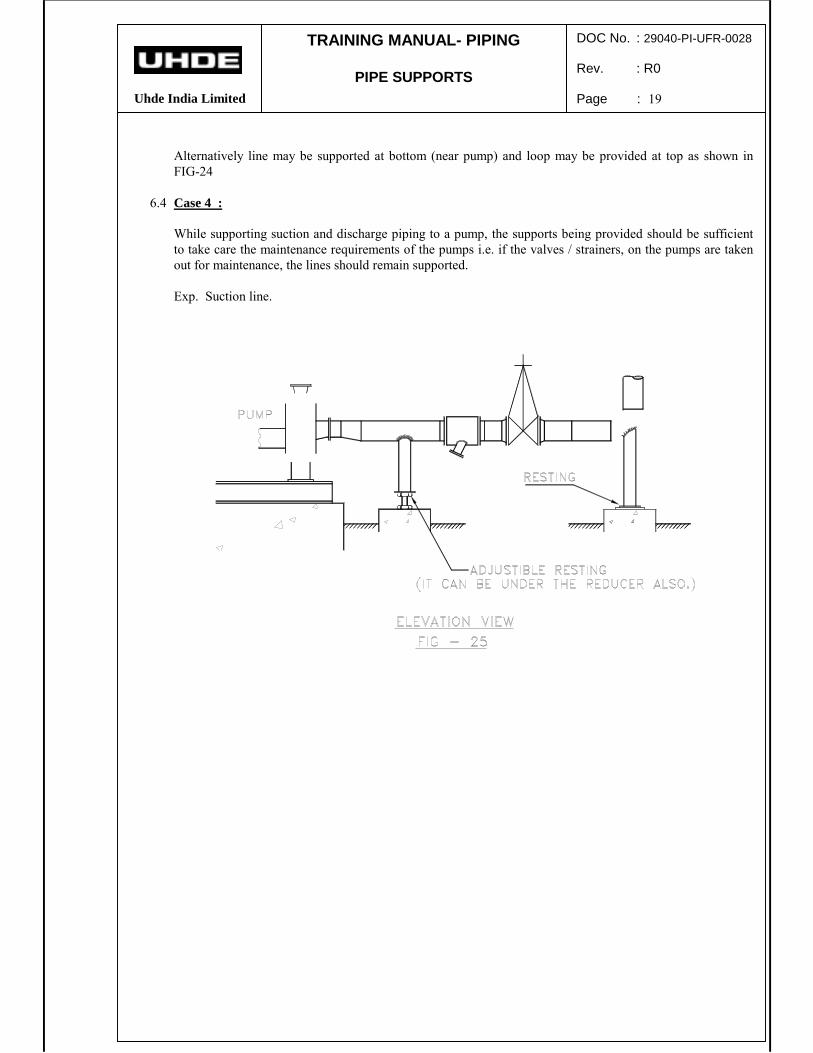
Alternatively line may be supported at bottom (near pump) and loop may be provided at top as shown inFIG-24
6.4 Case 4 :
While supporting suction and discharge piping to a pump, the supports being provided should be sufficientto take care the maintenance requirements of the pumps i.e. if the valves / strainers, on the pumps are takenout for maintenance, the lines should remain supported.
Exp. Suction line.
TRAINING MANUAL- PIPING
PIPE SUPPORTS
Uhde India Limited
DOC No. : 29040-PI-UFR-0028
Rev. : R0
Page : 20
TRAINING MANUAL- PIPING
PIPE SUPPORTS
Uhde India Limited
DOC No. : 29040-PI-UFR-0028
Rev. : R0
Page : 21
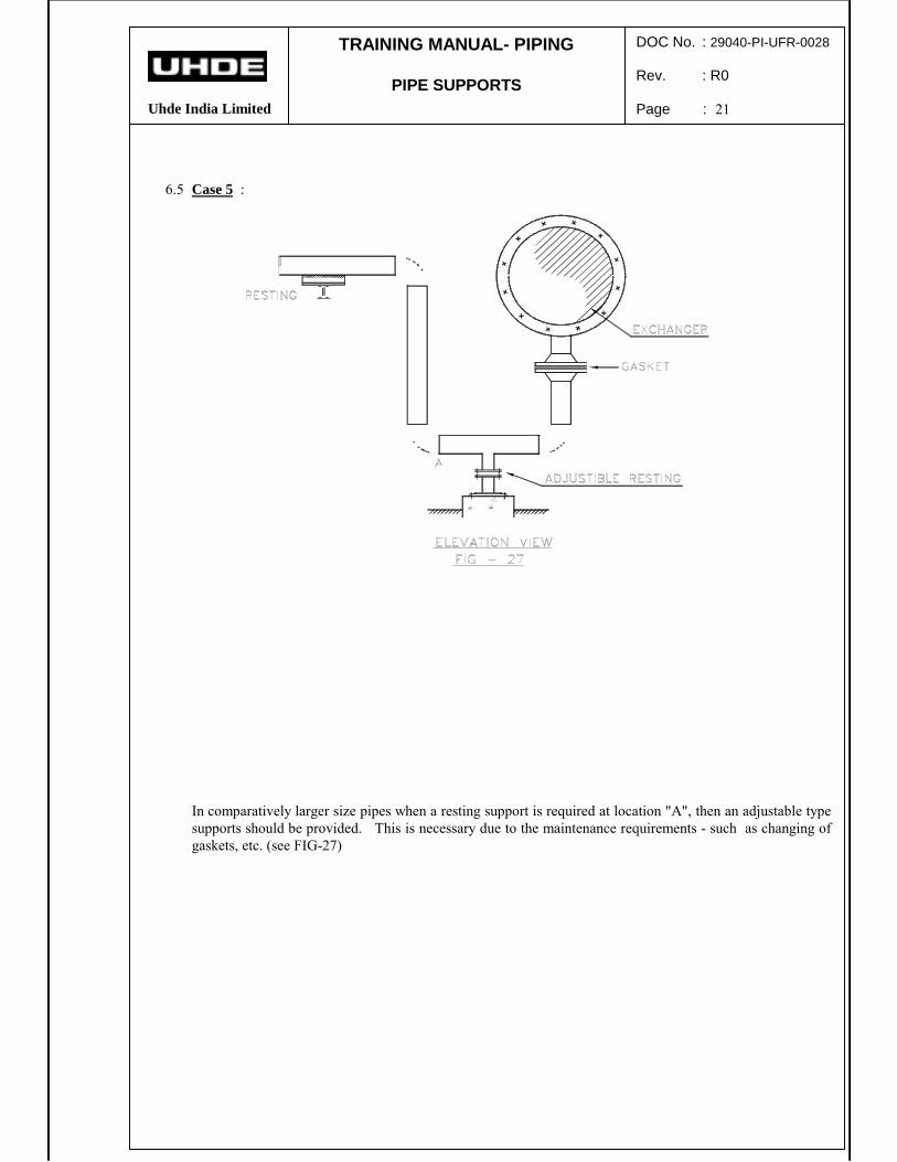
6.5 Case 5 :
In comparatively larger size pipes when a resting support is required at location "A", then an adjustable typesupports should be provided. This is necessary due to the maintenance requirements - such as changing ofgaskets, etc. (see FIG-27)
TRAINING MANUAL- PIPING
PIPE SUPPORTS
Uhde India Limited
DOC No. : 29040-PI-UFR-0028
Rev. : R0
Page : 22
7.0 FIXED SADDLE LOCATION FOR EXCHANGERS
A horizontal equipment will normally have two supports, saddle type. Normally one of them is made fixedand the other sliding type.Enclosed sketch showing a few typical cases will make the concept clear.
7.1 Case - 1
For the long vessel as shown in figure 28, selection of fixed saddle is decided by stiff connection 'A'. Now ifpumps are located at 'B' then expansion of 15mm (vessel expansion) and 5mm (pump line expansion) i.e.total 20mm will load the pump nozzle excessively.
If pumps are located at 'C' then expansion of the pump line will nullify the vessel expansion, since both are inthe same direction hence this type of arrangement should be preferred if possible.
TRAINING MANUAL- PIPING
PIPE SUPPORTS
Uhde India Limited
DOC No. : 29040-PI-UFR-0028
Rev. : R0
Page : 23
7.2 Case - 2
In such case if saddle 'A' is fixed in figure 29, total expansion of 13m will be required to be absorbed bypipe line.
If saddle 'B' is fixed then vessel expansion of 4m will be nullified by pipeline expansion of 4m and onlydifferential expansion of 9 m will be required to be absorbed.
7.3 Case - 3
In such case by looking at line size in figure 30, one may think that more attention be given to 20"connection. But looking correctly, saddle selection does not make any difference as both are at equaldistance from 20" pipe line. Then selection should be based in favour of 8" pump line i.e. saddle 'B' shouldbe fixed to reduce load on the pump.
Where ever it is possible to make a flexible piping to the pump, then in such situations, it is possible to makeboth the saddles, SLIDING type.
In conclusion fixed saddle should be so chosen that expansion of vessel towards sliding saddle tends tonullify or substantially reduce differential expansion passed onto connected pipe line. Fixed saddle shouldbe close to stiff piping connections to the equipment.
TRAINING MANUAL- PIPING
PIPE SUPPORTS
Uhde India Limited
DOC No. : 29040-PI-UFR-0028
Rev. : R0
Page : 24
8.0 PIPE SUPPORTS, GENERAL CONSIDERATION FOR DIFFERENT PIPING SYSTEM :
The construction features of various type of pipe supports described in the earlier sections vary depending onthe type of piping system where the support is intended to be used. Following type of piping systems arecommonly used in a chemical process plant.
The un-insulated carbon steel pipe (bare pipe) generally rests directly on the secondary support. For big diapipes generally NB ≥ 14", a pad is needed to avoid ovality formation in pipe at support. Generally U-boltscan be used at guides. Guide lugs can also be used. For fix point at non-critical locations, beams need to bewelded at bottom of pipe.
8.2 UN-INSULATED S.S. PIPING :
The un-insulated, stainless steel pipe do not rest directly on the secondary supports. Shoe type support withclamp of carbon steel is used for support. A thin stainless steel sheet or an asbestos cloth is used betweenpipe and clamp.
me
Highlight
TRAINING MANUAL- PIPING
PIPE SUPPORTS
Uhde India Limited
DOC No. : 29040-PI-UFR-0028
Rev. : R0
Page : 25
8.3 HOT INSULATED C.S. PIPING :
The hot insulated C.S. Piping never rests directly on secondary support. Shoe type support of carbon steelwith or without clamp is used. Trunnion type supports can be used if not objected by client / some licensors.U-bolts are not used.
8.4 HOT INSULATED S.S. PIPING :
The hot insulated stainless steel piping ( ≤ 350º C) will generally use shoe type support of carbon steel withclamp. A thin stainless steel sheet or an asbestos cloth is used between pipe and clamp. When welded typeshoe is required, then the pipe shall have an S.S pad welded to pipe. The C.S. shoe shall be welded to S.S.pad.
When Trunnion is used, a short length of trunnion will be of S.S. or a S.S. pad shall be used.
8.5 HOT INSULATED A.S. PIPING :
The hot insulated Alloy Steel piping shall generally use shoe with clamp. When ever essential, welded typeshoe can be used. Trunnion type supports can be used if accepted by client / licensor.
The material of clamp and shoe shall be carbon steel or alloy steel depending on the pipe temperature.
8.6 COLD INSULATED PIPING :
Cold insulated piping generally use pipe shoe with clamps of carbon steel. The clamps are put over the coldinsulation blocks. Pipe shoe with clamp, put directly on the cold pipe will need special insulating blocksbetween pipe shoe base plate and the secondary support member. In this case the support material need tobe compatible with the pipe temperature. Trunnion type supports are generally avoided.
8.7 PLASTIC PIPING :
Plastic being a weak and soft material as compared to metallic piping, it is vulnerable to local stressing /notching. Therefore the pipe supports used for plastic piping, necessarily employ a clamp-shoe assembly (ofcarbon steel) with a soft PVC sheet in between pipe and clamp.