96
User Guide C-WARE DEVELOPMENT SYSTEM C-WARE DEVELOPMENT SYSTEM VERSION 2.0 CDS20UG-UG/D Rev 07

User Guide
C-WARE DEVELOPMENT SYSTEM
C-WARE DEVELOPMENT SYSTEM VERSION 2.0
CDS20UG-UG/D
Rev 07

C-Ware Development System User Guide
C-WARE DEVELOPMENT SYSTEM, VERSION 2.0
C-WARE SOFTWARE TOOLSET, VERSION 2.3
CDS20UG-UG/DRev 07

Copyright © 2003 Motorola, Inc. All rights reserved. No part of this documentation may be reproduced in any form or by any means or used to make any derivative work (such as translation, transformation, or adaptation) without written permission from Motorola.
Motorola reserves the right to revise this documentation and to make changes in content from time to time without obligation on the part of Motorola to provide notification of such revision or change.
Motorola provides this documentation without warranty, term, or condition of any kind, either implied or expressed, including, but not limited to, the implied warranties, terms or conditions of merchantability, satisfactory quality, and fitness for a particular purpose. Motorola may make improvements or changes in the product(s) and/or the program(s) described in this documentation at any time.
C-3e, C-5, C-5e, C-Port, C-Ware, Q-3, and Q-5 are all trademarks of C-Port, a Motorola Company. Motorola and the stylized Motorola logo are registered in the US Patent & Trademark Office. All other product or service names are the property of their respective owners.

MOTOROLA GENERAL BUSINESS INFORMATION
CDS20UG-UG/D
Rev 06
CONTENTS
About This GuideGuide Overview . . . . . . . . . . . . . . . . . . . . . . . . . . . . . . . . . . . . . . . . . . . . . . . . . . . . . . . . . . . . . . . . . . . 13Using PDF Documents . . . . . . . . . . . . . . . . . . . . . . . . . . . . . . . . . . . . . . . . . . . . . . . . . . . . . . . . . . . . . . 14Guide Conventions . . . . . . . . . . . . . . . . . . . . . . . . . . . . . . . . . . . . . . . . . . . . . . . . . . . . . . . . . . . . . . . . . 15References to CST Pathnames . . . . . . . . . . . . . . . . . . . . . . . . . . . . . . . . . . . . . . . . . . . . . . . . . . . . . . . . 16Revision History . . . . . . . . . . . . . . . . . . . . . . . . . . . . . . . . . . . . . . . . . . . . . . . . . . . . . . . . . . . . . . . . . . . 17Related Product Documentation . . . . . . . . . . . . . . . . . . . . . . . . . . . . . . . . . . . . . . . . . . . . . . . . . . . . . . . 21
CHAPTER 1 Using the C-Ware Development SystemOverview . . . . . . . . . . . . . . . . . . . . . . . . . . . . . . . . . . . . . . . . . . . . . . . . . . . . . . . . . . . . . . . . . . . . . . . . . 23Startup . . . . . . . . . . . . . . . . . . . . . . . . . . . . . . . . . . . . . . . . . . . . . . . . . . . . . . . . . . . . . . . . . . . . . . . . . . 24
CDS Supported Software . . . . . . . . . . . . . . . . . . . . . . . . . . . . . . . . . . . . . . . . . . . . . . . . . . . . . . . . 24Startup Sequence . . . . . . . . . . . . . . . . . . . . . . . . . . . . . . . . . . . . . . . . . . . . . . . . . . . . . . . . . . . . . . 24
Controls and Indicators . . . . . . . . . . . . . . . . . . . . . . . . . . . . . . . . . . . . . . . . . . . . . . . . . . . . . . . . . . . . . . 25C-5 Switch Module Switch Settings . . . . . . . . . . . . . . . . . . . . . . . . . . . . . . . . . . . . . . . . . . . . . . . . . . . 26Using the CDS Without a C-5 Switch Module . . . . . . . . . . . . . . . . . . . . . . . . . . . . . . . . . . . . . . . . . . . . 29Using the CDS with External Test Equipment . . . . . . . . . . . . . . . . . . . . . . . . . . . . . . . . . . . . . . . . . . . . 29CDS Troubleshooting . . . . . . . . . . . . . . . . . . . . . . . . . . . . . . . . . . . . . . . . . . . . . . . . . . . . . . . . . . . . . . . 30Introduction to Host Application Development . . . . . . . . . . . . . . . . . . . . . . . . . . . . . . . . . . . . . . . . . . . 31Warranty and Liability Limitations . . . . . . . . . . . . . . . . . . . . . . . . . . . . . . . . . . . . . . . . . . . . . . . . . . . . . 31
CHAPTER 2 Using Serial Bus RegistersOverview . . . . . . . . . . . . . . . . . . . . . . . . . . . . . . . . . . . . . . . . . . . . . . . . . . . . . . . . . . . . . . . . . . . . . . . . . 33Roles for Registers . . . . . . . . . . . . . . . . . . . . . . . . . . . . . . . . . . . . . . . . . . . . . . . . . . . . . . . . . . . . . . . . . 34Identification Bits . . . . . . . . . . . . . . . . . . . . . . . . . . . . . . . . . . . . . . . . . . . . . . . . . . . . . . . . . . . . . . . . . . 34Using Registers . . . . . . . . . . . . . . . . . . . . . . . . . . . . . . . . . . . . . . . . . . . . . . . . . . . . . . . . . . . . . . . . . . . . 34C-5 Switch Module Registers . . . . . . . . . . . . . . . . . . . . . . . . . . . . . . . . . . . . . . . . . . . . . . . . . . . . . . . . . 36Ethernet/OC-3c/Gigabit Combo PIM Registers . . . . . . . . . . . . . . . . . . . . . . . . . . . . . . . . . . . . . . . . . . . 3710/100 Ethernet PIM Registers . . . . . . . . . . . . . . . . . . . . . . . . . . . . . . . . . . . . . . . . . . . . . . . . . . . . . . . 38
CDS20UG-UG/D REV 06

6 CONTENTS
Gigabit Ethernet PIM Registers . . . . . . . . . . . . . . . . . . . . . . . . . . . . . . . . . . . . . . . . . . . . . . . . . . . . . . . 39OC-3c PIM Registers . . . . . . . . . . . . . . . . . . . . . . . . . . . . . . . . . . . . . . . . . . . . . . . . . . . . . . . . . . . . . . . . 41OC-12c PIM Registers . . . . . . . . . . . . . . . . . . . . . . . . . . . . . . . . . . . . . . . . . . . . . . . . . . . . . . . . . . . . . . . 42
CHAPTER 3 Debugging with the C-Ware Development SystemOverview . . . . . . . . . . . . . . . . . . . . . . . . . . . . . . . . . . . . . . . . . . . . . . . . . . . . . . . . . . . . . . . . . . . . . . . . . 45Debugging Techniques . . . . . . . . . . . . . . . . . . . . . . . . . . . . . . . . . . . . . . . . . . . . . . . . . . . . . . . . . . . . . . 45Selecting a Debugging Strategy . . . . . . . . . . . . . . . . . . . . . . . . . . . . . . . . . . . . . . . . . . . . . . . . . . . . . . . 46Using the C-Ware Debugger with a NP Device . . . . . . . . . . . . . . . . . . . . . . . . . . . . . . . . . . . . . . . . . . . 47Debugging After a Panic Condition on a NP Device . . . . . . . . . . . . . . . . . . . . . . . . . . . . . . . . . . . . . . . . 49Debugging Host Application Programs That Interact With the C-Ware Simulator . . . . . . . . . . . . . . . . 50
CHAPTER 4 Using the DCP ShellOverview . . . . . . . . . . . . . . . . . . . . . . . . . . . . . . . . . . . . . . . . . . . . . . . . . . . . . . . . . . . . . . . . . . . . . . . . . 53DCP Shell Features . . . . . . . . . . . . . . . . . . . . . . . . . . . . . . . . . . . . . . . . . . . . . . . . . . . . . . . . . . . . . . . . . 53
Command Line Editing . . . . . . . . . . . . . . . . . . . . . . . . . . . . . . . . . . . . . . . . . . . . . . . . . . . . . . . . . . 53Command Name Abbreviation . . . . . . . . . . . . . . . . . . . . . . . . . . . . . . . . . . . . . . . . . . . . . . . . . . . . 53Command History . . . . . . . . . . . . . . . . . . . . . . . . . . . . . . . . . . . . . . . . . . . . . . . . . . . . . . . . . . . . . . 53Help Features . . . . . . . . . . . . . . . . . . . . . . . . . . . . . . . . . . . . . . . . . . . . . . . . . . . . . . . . . . . . . . . . . 54
DCP Shell Commands . . . . . . . . . . . . . . . . . . . . . . . . . . . . . . . . . . . . . . . . . . . . . . . . . . . . . . . . . . . . . . . 54Command Syntax Summary . . . . . . . . . . . . . . . . . . . . . . . . . . . . . . . . . . . . . . . . . . . . . . . . . . . . . . 55Load a Package into the NP . . . . . . . . . . . . . . . . . . . . . . . . . . . . . . . . . . . . . . . . . . . . . . . . . . . . . . 56Load a Dynamic Load Module . . . . . . . . . . . . . . . . . . . . . . . . . . . . . . . . . . . . . . . . . . . . . . . . . . . . 58Unload a Dynamic Load Module . . . . . . . . . . . . . . . . . . . . . . . . . . . . . . . . . . . . . . . . . . . . . . . . . . 59Open Connection to the C-Ware Simulator . . . . . . . . . . . . . . . . . . . . . . . . . . . . . . . . . . . . . . . . . . 59PCI Bus Status . . . . . . . . . . . . . . . . . . . . . . . . . . . . . . . . . . . . . . . . . . . . . . . . . . . . . . . . . . . . . . . . 60Read From NP Memory . . . . . . . . . . . . . . . . . . . . . . . . . . . . . . . . . . . . . . . . . . . . . . . . . . . . . . . . . . 61Redirect PrintfListener Output . . . . . . . . . . . . . . . . . . . . . . . . . . . . . . . . . . . . . . . . . . . . . . . . . . . . 62Reset a NP Device . . . . . . . . . . . . . . . . . . . . . . . . . . . . . . . . . . . . . . . . . . . . . . . . . . . . . . . . . . . . . 62Displaying CDS System Information . . . . . . . . . . . . . . . . . . . . . . . . . . . . . . . . . . . . . . . . . . . . . . . 63Write to NP Memory . . . . . . . . . . . . . . . . . . . . . . . . . . . . . . . . . . . . . . . . . . . . . . . . . . . . . . . . . . . 63
Test Applications . . . . . . . . . . . . . . . . . . . . . . . . . . . . . . . . . . . . . . . . . . . . . . . . . . . . . . . . . . . . . . . . . . 64
CDS20UG-UG/D REV 06 MOTOROLA GENERAL BUSINESS INFORMATION

CONTENTS 7
CHAPTER 5 Using Host Environment SoftwareOverview . . . . . . . . . . . . . . . . . . . . . . . . . . . . . . . . . . . . . . . . . . . . . . . . . . . . . . . . . . . . . . . . . . . . . . . . . 67C-5 Device Driver . . . . . . . . . . . . . . . . . . . . . . . . . . . . . . . . . . . . . . . . . . . . . . . . . . . . . . . . . . . . . . . . . . 67PCI Bus Simulation . . . . . . . . . . . . . . . . . . . . . . . . . . . . . . . . . . . . . . . . . . . . . . . . . . . . . . . . . . . . . . . . . 68Printflistener . . . . . . . . . . . . . . . . . . . . . . . . . . . . . . . . . . . . . . . . . . . . . . . . . . . . . . . . . . . . . . . . . . . . . . 69C-Ware Debugger Agent . . . . . . . . . . . . . . . . . . . . . . . . . . . . . . . . . . . . . . . . . . . . . . . . . . . . . . . . . . . . 69
CHAPTER 6 Using DiagnosticsOverview . . . . . . . . . . . . . . . . . . . . . . . . . . . . . . . . . . . . . . . . . . . . . . . . . . . . . . . . . . . . . . . . . . . . . . . . . 71About the Diagnostics . . . . . . . . . . . . . . . . . . . . . . . . . . . . . . . . . . . . . . . . . . . . . . . . . . . . . . . . . . . . . . 72
Number and Targets for Diagnostics . . . . . . . . . . . . . . . . . . . . . . . . . . . . . . . . . . . . . . . . . . . . . . . 72One C-Ware Package File Produced Per Diagnostic . . . . . . . . . . . . . . . . . . . . . . . . . . . . . . . . . . . 73Order for Running Diagnostics . . . . . . . . . . . . . . . . . . . . . . . . . . . . . . . . . . . . . . . . . . . . . . . . . . . . 73Readme File Provided . . . . . . . . . . . . . . . . . . . . . . . . . . . . . . . . . . . . . . . . . . . . . . . . . . . . . . . . . . . 73
Source Code for Diagnostics . . . . . . . . . . . . . . . . . . . . . . . . . . . . . . . . . . . . . . . . . . . . . . . . . . . . . . . . . 74Object Files, Libraries, Executables, and Binaries . . . . . . . . . . . . . . . . . . . . . . . . . . . . . . . . . . . . . . . . . 75Building a Diagnostics Package . . . . . . . . . . . . . . . . . . . . . . . . . . . . . . . . . . . . . . . . . . . . . . . . . . . . . . . 76
Custom Diagnostics Make Targets . . . . . . . . . . . . . . . . . . . . . . . . . . . . . . . . . . . . . . . . . . . . . . . . 76Building the Standard Diagnostics . . . . . . . . . . . . . . . . . . . . . . . . . . . . . . . . . . . . . . . . . . . . . . . . . 76Building Diagnostics for Individual Targets . . . . . . . . . . . . . . . . . . . . . . . . . . . . . . . . . . . . . . . . . . 77Building and Running Diagnostics for Hardware Targets . . . . . . . . . . . . . . . . . . . . . . . . . . . . . . . 77Building and Running Diagnostics for Simulation Targets . . . . . . . . . . . . . . . . . . . . . . . . . . . . . . 79Building and Running Diagnostics for Acceptance Test Targets . . . . . . . . . . . . . . . . . . . . . . . . . 81Makefile for Diagnostics . . . . . . . . . . . . . . . . . . . . . . . . . . . . . . . . . . . . . . . . . . . . . . . . . . . . . . . . 81Widely used Compile/ Pre-processor Variables in Diagnostics Source Code . . . . . . . . . . . . . . . . 82Changing Diagnostics Behavior for Board Level Testing and Trace Output . . . . . . . . . . . . . . . . . 83
Diagnostics Packages . . . . . . . . . . . . . . . . . . . . . . . . . . . . . . . . . . . . . . . . . . . . . . . . . . . . . . . . . . . . . . . 84Device Numbers . . . . . . . . . . . . . . . . . . . . . . . . . . . . . . . . . . . . . . . . . . . . . . . . . . . . . . . . . . . . . . . . . . . 86Error Messages . . . . . . . . . . . . . . . . . . . . . . . . . . . . . . . . . . . . . . . . . . . . . . . . . . . . . . . . . . . . . . . . . . . . 88
Index . . . . . . . . . . . . . . . . . . . . . . . . . . . . . . . . . . . . . . . . . . . . . . . . . . . . . . . . . . . . . . . . . . . . . . . . . . . . . . . . . . . . 91
MOTOROLA GENERAL BUSINESS INFORMATION CDS20UG-UG/D REV 06

8 CONTENTS
CDS20UG-UG/D REV 06 MOTOROLA GENERAL BUSINESS INFORMATION

MOTOROLA GENERAL BUSINESS INFORMATION
CDS20UG-UG/D
Rev 06
FIGURES
1 Power Circuit Breaker . . . . . . . . . . . . . . . . . . . . . . . . . . . . . . . . . . . . . . . . . . . . . . . . . . . . . . . 242 C-Ware Debugger Connection to a Hardware C-Port NP . . . . . . . . . . . . . . . . . . . . . . . . . . . . 47
CDS20UG-UG/D REV 06

10 FIGURES
CDS20UG-UG/D REV 06 MOTOROLA GENERAL BUSINESS INFORMATION

MOTOROLA GENERAL BUSINESS INFORMATION
CDS20UG-UG/D
Rev 06
TABLES
1 Navigating Within a PDF Document . . . . . . . . . . . . . . . . . . . . . . . . . . . . . . . . . . . . . . . . . . . . 152 C-Ware Development System User Guide Revision History. . . . . . . . . . . . . . . . . . . . . . . . . . 173 C-Port Silicon and CST Documentation Set . . . . . . . . . . . . . . . . . . . . . . . . . . . . . . . . . . . . . . 214 CDS Supported Software . . . . . . . . . . . . . . . . . . . . . . . . . . . . . . . . . . . . . . . . . . . . . . . . . . . . 245 Controls and Indicators . . . . . . . . . . . . . . . . . . . . . . . . . . . . . . . . . . . . . . . . . . . . . . . . . . . . . . 256 Core Clock Source . . . . . . . . . . . . . . . . . . . . . . . . . . . . . . . . . . . . . . . . . . . . . . . . . . . . . . . . . . 277 TLU Clock Source. . . . . . . . . . . . . . . . . . . . . . . . . . . . . . . . . . . . . . . . . . . . . . . . . . . . . . . . . . . 288 BMU Clock Source. . . . . . . . . . . . . . . . . . . . . . . . . . . . . . . . . . . . . . . . . . . . . . . . . . . . . . . . . . 289 Troubleshooting Tips . . . . . . . . . . . . . . . . . . . . . . . . . . . . . . . . . . . . . . . . . . . . . . . . . . . . . . . . 3010 C-5 Switch Module Register Address 24 . . . . . . . . . . . . . . . . . . . . . . . . . . . . . . . . . . . . . . . . 3611 C-5 Switch Module Register Address 24 Field Descriptions . . . . . . . . . . . . . . . . . . . . . . . . . 3612 Ethernet/OC-3c/Gigabit Combo PIM Register Address 22 . . . . . . . . . . . . . . . . . . . . . . . . . . . 3713 Ethernet/OC-3c/Gigabit Combo PIM Register Address 22 Field Descriptions . . . . . . . . . . . . 3714 Ethernet/OC-3c/Gigabit Combo PIM Register Address 23 . . . . . . . . . . . . . . . . . . . . . . . . . . . 3715 Ethernet/OC-3c/Gigabit Combo PIM Register Address 23 Field Descriptions . . . . . . . . . . . . 3816 10/100 Ethernet PIM Register Address 22 . . . . . . . . . . . . . . . . . . . . . . . . . . . . . . . . . . . . . . . 3817 10/100 Ethernet PIM Register Address 22 Field Descriptions . . . . . . . . . . . . . . . . . . . . . . . . 3818 Gigabit Ethernet PIM Register Address 22 . . . . . . . . . . . . . . . . . . . . . . . . . . . . . . . . . . . . . . . 3919 Gigabit Ethernet PIM Register Address 22 Field Descriptions . . . . . . . . . . . . . . . . . . . . . . . . 3920 Gigabit Ethernet PIM Register Address 23 . . . . . . . . . . . . . . . . . . . . . . . . . . . . . . . . . . . . . . . 4021 Gigabit Ethernet PIM Register Address 23 Field Descriptions . . . . . . . . . . . . . . . . . . . . . . . . 4022 OC-3c PIM Register Address 22 . . . . . . . . . . . . . . . . . . . . . . . . . . . . . . . . . . . . . . . . . . . . . . . 4123 OC-3c PIM Register Address 22 Field Descriptions . . . . . . . . . . . . . . . . . . . . . . . . . . . . . . . . 4124 OC-12c PIM Register Address 22 . . . . . . . . . . . . . . . . . . . . . . . . . . . . . . . . . . . . . . . . . . . . . . 4225 OC-12c PIM Register Address 22 Field Descriptions . . . . . . . . . . . . . . . . . . . . . . . . . . . . . . . 4226 OC-12c PIM Register Address 23 . . . . . . . . . . . . . . . . . . . . . . . . . . . . . . . . . . . . . . . . . . . . . . 4327 OC-12c PIM Register Address 23 Field Descriptions . . . . . . . . . . . . . . . . . . . . . . . . . . . . . . . 4328 PCIsrv Options . . . . . . . . . . . . . . . . . . . . . . . . . . . . . . . . . . . . . . . . . . . . . . . . . . . . . . . . . . . . . 68
CDS20UG-UG/D REV 06

12 TABLES
29 Preprocessor Definitions Used in Diagnostics Source Code. . . . . . . . . . . . . . . . . . . . . . . . . . 8230 C-5 Network Processor “Standard” Diagnostic Packages . . . . . . . . . . . . . . . . . . . . . . . . . . . 8431 Diagnostics Device Numbers . . . . . . . . . . . . . . . . . . . . . . . . . . . . . . . . . . . . . . . . . . . . . . . . . 8632 Diagnostics Error Messages . . . . . . . . . . . . . . . . . . . . . . . . . . . . . . . . . . . . . . . . . . . . . . . . . . 88
CDS20UG-UG/D REV 06 MOTOROLA GENERAL BUSINESS INFORMATION
MOTOROLA GENERAL BUSINESS INFORMATION
CDS20UG-UG/D
Rev 07
ABOUT THIS GUIDE
Guide Overview The C-Ware™ Development System User Guide describes setup and operation of the C-Ware Development System (CDS).
This guide is designed for use by software and hardware developers designing with the C-Port C-5, C-5e, and C-3e Network Processors (NP). It assumes familiarity with the C-Ware Software Toolset (CST), the WindRiver® Systems VxWorks® real-time operating system, and developer’s knowledge of networking hardware.
This guide covers the following topics:
• Using the C-Ware Development System
• Using Serial Bus Registers
• Debugging with the C-Ware Development System
• Using the DCP Shell
• Using Host Environment Software
• Using Diagnostics
CDS20UG-UG/D REV 07

14 ABOUT THIS GUIDE
Using PDF Documents Electronic documents are provided as PDF files. Open and view them using the Adobe® Acrobat® Reader application, version 3.0 or later. If necessary, download the Acrobat Reader from the Adobe Systems, Inc. web site:
http://www.adobe.com/prodindex/acrobat/readstep.html
PDF files offer several ways for moving among the document’s pages, as follows:
• To move quickly from section to section within the document, use the Acrobat bookmarks that appear on the left side of the Acrobat Reader window. The bookmarks provide an expandable ‘outline’ view of the document’s contents. To display the document’s Acrobat bookmarks, press the ‘Display both bookmarks and page’ button on the Acrobat Reader tool bar.
• To move to the referenced page of an entry in the document’s Contents or Index, click on the entry itself, each of which is “hot linked.”
• To follow a cross-reference to a heading, figure, or table, click the blue text.
• To move to the beginning or end of the document, to move page by page within the document, or to navigate among the pages you displayed by clicking on hyperlinks, use the Acrobat Reader navigation buttons shown in this figure:
Beginning of document End of document
Next pagePrevious page
Previous or next hyperlink
CDS20UG-UG/D REV 07 MOTOROLA GENERAL BUSINESS INFORMATION

Guide Conventions 15
Table 1 summarizes how to navigate within an electronic document.
Guide Conventions The following visual elements are used throughout this guide, where applicable:
This icon and text designates information of special note.
Warning: This icon and text indicate a potentially dangerous procedure. Instructions contained in the warnings must be followed.
Warning: This icon and text indicate a procedure where the reader must take precautions regarding laser light.
This icon and text indicate the possibility of electrostatic discharge (ESD) in a procedure that requires the reader to take the proper ESD precautions.
Table 1 Navigating Within a PDF Document
TO NAVIGATE THIS WAY CLICK THIS
Move from section to section within the document.
A bookmark on the left side of the Acrobat Reader window
Move to an entry in the document’s Contents or Index.
The entry itself
Follow a cross-reference (highlighted in blue text).
The cross-reference text
Move page by page. The appropriate Acrobat Reader navigation buttons
Move to the beginning or end of the document.
The appropriate Acrobat Reader navigation buttons
Move backward or forward among a series of hyperlinks you have selected.
The appropriate Acrobat Reader navigation buttons
MOTOROLA GENERAL BUSINESS INFORMATION CDS20UG-UG/D REV 07

16 ABOUT THIS GUIDE
References to CST Pathnames
You typically install the C-Ware Software Toolset (CST) on your development workstation in a directory path suggested by the installation procedure, such as:
• C:\C-Port\Cstx.y\ (on Windows NT)
• /usr/yourlogin/C-Port/Cstx.y/ (on Sun SPARC Solaris)
or:
/usr/cport/C-Port/Cstx.y/
or:
/opt/C-Port/Cstx.y/
where ‘x’ is a major version number and ‘y’ is a minor (or intermediate) version number.
You typically install each CST version under some directory path ...\C-Port\Cstx.y\. However, the user can install the CST in any directory on the development workstation. The user can also install more than one CST version on the same workstation.
Therefore, to refer to installed CST directories, we use pathnames that are relative to the ...\C-Port\Cstx.y\ path, which is the “root” of a given CST installation.
For example, the apps\gbeSwitch\ directory path refers to the location of the Gigabit Ethernet Switch application that is installed as part of the CST. The full path of this directory on a Windows NT system might be C:\C-Port\Cst2.1\apps\gbeSwitch\, so this convention is convenience for shortening the pathname.
Other top-level directories that are installed as part of the CST include bin\, diags\, Documentation\, services\, and so on. These directories are described in the C-Ware Software Toolset Getting Started Guide document, which is part of the CST documentation set.
CDS20UG-UG/D REV 07 MOTOROLA GENERAL BUSINESS INFORMATION

Revision History 17
Revision History Table 2 provides details about changes made for each revision of this guide.
Table 2 C-Ware Development System User Guide Revision History
REVISION DATE CST REVISION CDS REVISION CHANGES
May 14, 2003 2.3 2.0 In Chapter 6 updated the names of diagnostic packages.
November 1, 2002 2.2 2.0 In Chapter 6 updated the procedures for building and running the CST’s standard diagnostics on both NP hardware and the C-Ware Simulator.
July 19, 2002 2.1.1 2.0 In Chapter 6 updated the procedures for building and running the CST’s standard diagnostics on both NP hardware and the C-Ware Simulator; updated the list of standard diagnostics and FULLMEM diagnostics, removed documentation of all other non-supported diagnostics.
June 12, 2002 2.1 2.0 Added the section “References to CST Pathnames” in About This Guide. Updated the list of Related Product Documents in About This Guide. Throughout the document, updated the text to refer to both C-5 Switch Module and C-5eSwitch Module. Throughout the document, updated references to the C-Ware Simulation Environment and C-Ware Simulator. Added Overview section in some chapters. In Chapter 6 corrected all pathnames for diagnostics software included in the C-Ware Software Toolset.
MOTOROLA GENERAL BUSINESS INFORMATION CDS20UG-UG/D REV 07

18 ABOUT THIS GUIDE
April 12, 2002 2.1 2.0 In Chapter 1 changed the meaning of the data in Table 6, Table 7, and Table 8 to 0 = ON and 1 = OFF. In Chapter 3 added the section “Debugging After a Panic Condition on a NP Device”. In Chapter 4:
• Added the section “DCP Shell Features”.
• In the section “DCP Shell Commands” added the subsections “Load a Dynamic Load Module” and “Unload a Dynamic Load Module”. Described new arguments, used for diagnostics, to DCP Shell ‘packload’ command in the subsection “Load a Package into the NP”.
• Described new arguments, used for diagnostics, to DCP Shell ‘packload’ command in the subsection “Building and Running Diagnostics for Hardware Targets”.
• In the section “Test Applications” replaced the sample output for the ‘dmxRx’ test application.
• Removed a redundant section about editing DCP Shell command history.
• Made subsections explicit under the section “Overview”.
• In the section “Diagnostics Packages” added a new table to distinguish lists of available “standard” and “additional SDP” diagnostics.
Table 2 C-Ware Development System User Guide Revision History (continued)
REVISION DATE CST REVISION CDS REVISION CHANGES
CDS20UG-UG/D REV 07 MOTOROLA GENERAL BUSINESS INFORMATION

Revision History 19
April 12, 2002, continued
2.1 2.0 Also in Chapter 4:
• Organized all build-related information in subsections under the section “Building a Diagnostics Package”. Added new information about specific diagnostics-related preprocessor definitions and makefile variables in the sections “Custom Makefile Variables for Building Diagnostics.”, “Widely used Compile/ Pre-processor Variables in Diagnostics Source Code”, and “Changing Diagnostics Behavior for Board Level Testing and Trace Output”. In the section “Custom Diagnostics Make Targets” added new build targets.
September 14, 2001
2.0 2.0 Beginning of Chapter 6 has been rewritten to reflect the new CST build directory structure.
July 9, 2001 1.8 2.0 Under the section “Debugging Host Application Programs That Interact With the C-Ware Simulator” updated the steps for preparing a debugging session on the Host Application Module so that it communicates with the C-5 Simulator. Under the section “Using the C-Ware Debugger with a NP Device”, clarified that the C-Ware Debugger must be previously and separately started before performing a ‘packload’ that loads a debuggable C-5 package.
July 9, 2001 continued
1.8 2.0 Under the section “DCP Shell Commands” updated the set of supported DCP Shell commands and corrected the description of each command. Additions and corrections in the tables shown in Chapter 6.
April 18, 2001 1.7 2.0 Typographic corrections throughout
Table 2 C-Ware Development System User Guide Revision History (continued)
REVISION DATE CST REVISION CDS REVISION CHANGES
MOTOROLA GENERAL BUSINESS INFORMATION CDS20UG-UG/D REV 07

20 ABOUT THIS GUIDE
December 1, 2000 1.6 2.0 To support CST Version 1.6 (no change to technical content):
• Updated revisions of Switch Module, 10/100 Ethernet and OC-12c PIMs
• Clarified status of blue LEDs
• Added CDS supported software
• Changed DCP to network processor
• Enhanced troubleshooting tips
• Added warranty and liability limitations section
• Added technical support section
Table 2 C-Ware Development System User Guide Revision History (continued)
REVISION DATE CST REVISION CDS REVISION CHANGES
CDS20UG-UG/D REV 07 MOTOROLA GENERAL BUSINESS INFORMATION

Related Product Documentation 21
Related Product Documentation
Table 3 lists the user and reference documentation for the C-Port silicon, C-Ware Development System, and the C-Ware Software Toolset.
Table 3 C-Port Silicon and CST Documentation Set
DOCUMENT SUBJECT DOCUMENT NAME PURPOSE DOCUMENT ID
Processor Information
C-5 Network Processor Architecture Guide Describes the full architecture of the C-5 network processor.
C5NPARCH-RM
C-5 Network Processor Data Sheet Describes hardware design specifications for the C-5 network processor.
C5NPDATA-DS
C-5e/C-3e Network Processor Architecture Guide
Describes the full architecture of the C-5e and C-3e network processors.
C53C3EARCH-RM
C-5e Network Processor Data Sheet Describes hardware design specifications for the C-5e network processor.
C5ENPDATA-DS
M-5 Channel Adapter Architecture Guide Describes the full architecture of the M-5 channel adapter.
M5CAARCH-RM
Q-5/Q-3 Traffic Management Coprocessor Architecture Guide
Describes the full architecture of the Q-5and Q-3 traffic management coprocessors.
Q5Q3ARCH-RM
Hardware Development Tools
C-Ware Development System Getting Started Guide
Describes installation of the CDS. CDS20GSG-UG
C-Ware Development System User Guide Describes operation of the CDS. CDS20UG-UG
Software Development Tools
C-Ware Software Toolset Getting Started Guide Describes how to quickly become acquainted with the CST’s software development tools for a given CST platform.
CSTGSGW-UG (Windows)CSTGSGS-UG (Sun SPARC Solaris)
C-Ware Application Building Guide Describes tools to build executable programs for the C-Port network processors or simulators.
CSTABG-UG
C-Ware Debugger User Guide Describes the GNU-based tool for debugging software running on either the C-Port network processorsor simulators.
CSTDBGUG-UG
C-Ware Integrated Performance Analyzer User Guide
Describes use of theIntegrated Performance Analyzer tool for gathering performance metrics of a C-Port NP-based application running under the simulator.
CSTIPAUG-UG
C-Ware Simulation Environment User Guide Describes how to configure and run a simulation of a C-Port NP-based application using simulator tools.
CSTSIMUG-UG
MOTOROLA GENERAL BUSINESS INFORMATION CDS20UG-UG/D REV 07

22 ABOUT THIS GUIDE
Application Development
C-Ware Application Design Guide Describes design guidelines and trade-offs for implementing new C-Port NP-based communications applications.
CSTAPDG-UG
C-Ware API User Guide Describes the subsystems and services that make up the C-Ware Applications Programming Interface (API) for C-Port NP-based communications applications.
CSTAPIUG-UG
C-Ware Host Application Programming Guide Describes the CST software infrastructure and APIs that support host based communications applications.
CSTHAPG-UG
C-Ware Microcode Programming Guide Describes programming the C-Port network processor’s Serial Data Processors and Fabric Processor.
CSTMCPG-UG
C-Ware TMC API User Guide Provides a reference for the Traffic Management Coprocessor (TMC) API. This guide includes a discussion and example of creating a scheduler hierarchy.
CSTQ5API-UG
Other Documents
Answers to FAQs About C-Ware Software Toolset Version 2.0
Describes how the directory architecture provided in C-Ware Software Toolset Version 2.0 differs from previous CST releases.
CSTOAFAQ-UG
Build System Conventions Describes the key features of the C-Ware Software Toolset’s provided environment for building software.
CSTOBSC-UG
C-Ware Software Toolset Application Guidelines Describes the criteria for how software components comply with the C-Ware Software Toolset’s provided environment for building software.
CSTOCAG-UG
Table 3 C-Port Silicon and CST Documentation Set (continued)
DOCUMENT SUBJECT DOCUMENT NAME PURPOSE DOCUMENT ID
CDS20UG-UG/D REV 07 MOTOROLA GENERAL BUSINESS INFORMATION

MOTOROLA GENERAL BUSINESS INFORMATION
CDS20UG-UG/D
Rev 06
Chapter 1USING THE C-WARE DEVELOPMENT SYSTEM
Overview This chapter covers using the C-Ware Development System (CDS), including topics on using the Host Environment Software. Topics include:
• Startup
• Controls and Indicators
• C-5 Switch Module Switch Settings
• Using the CDS Without a C-5 Switch Module
• Using the CDS with External Test Equipment
• CDS Troubleshooting
• Introduction to Host Application Development
• Warranty and Liability Limitations
CDS20UG-UG/D REV 06

24 CHAPTER 1: USING THE C-WARE DEVELOPMENT SYSTEM
Startup After the CDS has been configured as described in the C-Ware Development System Getting Started Guide, at boot time the Host Application Module loads its operating system (by default, a copy of CST-provided file bin\VxWorks.dcp) via FTP from a location specified in the CDS’s boot PROM parameters. Thus, before starting the CDS, the system where the Host Application Module’s operating system image resides must be running.
CDS Supported Software Ensure the CDS and software are compatible. CDS Version 2.0 supports the following software versions:
Startup Sequence 1 Start the system that has the VxWorks image and FTP server.
2 Turn the power on using the circuit breaker on the bottom rail at the back of the chassis. The DC on/off switch on the front of the chassis is not used. Make sure that all the power supply indicators on the front of the chassis are lit.
Figure 1 Power Circuit Breaker
Table 4 CDS Supported Software
SUPPORTED SOFTWARE USE VERSION
WindRiver VxWorks (RTOS) Pre-loaded on CDS’s Host Application Module 5.4 or later
WindRiver System Tornado Loaded on C-Ware Software Toolset development system
2.0 or later
C-Port C-Ware Software Toolset Loaded on C-Ware Software Toolset development system
1.6 or later
CDS20UG-UG/D REV 06 MOTOROLA GENERAL BUSINESS INFORMATION
Controls and Indicators 25
Booting completes with the appearance of the DCP Shell prompt on the serially connected terminal or terminal emulation program. See Chapter 4 for information on using the DCP Shell.
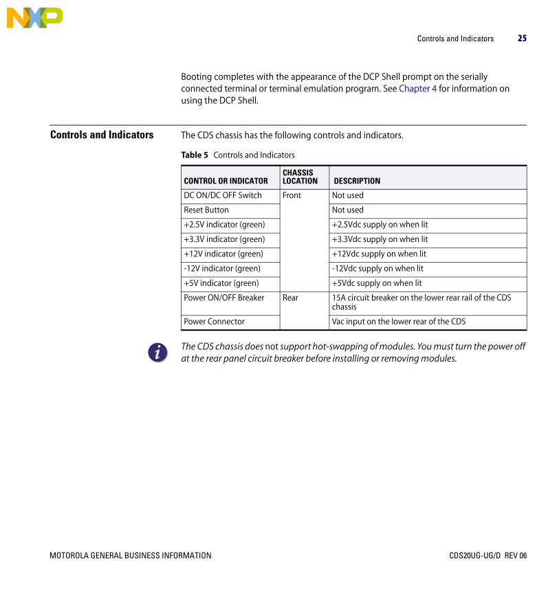
Controls and Indicators The CDS chassis has the following controls and indicators.
The CDS chassis does not support hot-swapping of modules. You must turn the power off at the rear panel circuit breaker before installing or removing modules.
Table 5 Controls and Indicators
CONTROL OR INDICATORCHASSISLOCATION DESCRIPTION
DC ON/DC OFF Switch Front Not used
Reset Button Not used
+2.5V indicator (green) +2.5Vdc supply on when lit
+3.3V indicator (green) +3.3Vdc supply on when lit
+12V indicator (green) +12Vdc supply on when lit
-12V indicator (green) -12Vdc supply on when lit
+5V indicator (green) +5Vdc supply on when lit
Power ON/OFF Breaker Rear 15A circuit breaker on the lower rear rail of the CDS chassis
Power Connector Vac input on the lower rear of the CDS
MOTOROLA GENERAL BUSINESS INFORMATION CDS20UG-UG/D REV 06

26 CHAPTER 1: USING THE C-WARE DEVELOPMENT SYSTEM
C-5 Switch Module Switch Settings
The C-5 Switch Module uses DIP switches SW1 through SW6 to set the XP, BMU, and TLU clock speed settings of the Motorola MC 12429 synthesized clock source. These settings are made at the factory and should not be changed under normal usage.
Change the C-5 Switch Module clock speed settings with care. Incorrect setting of the clock speed switches can result in physical damage to the C-5 by running the device at higher than its rated speed.
Setting the C-5’s core clock speed lower than the TLU and BMU clock speeds can result in C-5 operating errors.
You can change switch settings with the CDS on or off, but for the switch settings to take effect you must reset the CDS, either by pressing the reset button on the Host Application Module, or by cycling the power.
CDS20UG-UG/D REV 06 MOTOROLA GENERAL BUSINESS INFORMATION

C-5 Switch Module Switch Settings 27
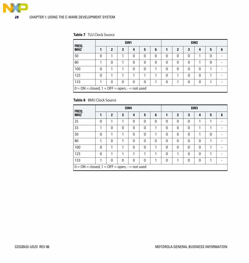
Table 6 through Table 8 on page 28 present the settings for C-5 Switch Module DIP switches SW1 through SW6 for each supported clock speed for the C-5 NP’s core clock, the C-5 NP’s TLU, and C-5 NP’s BMU.
Table 6 Core Clock Source
FREQ.MHZ
SW6 SW5
1 2 3 4 5 6 1 2 3 4 5 6
50 0 1 1 0 0 1 0 0 0 1 0 -
100 0 1 1 0 0 1 0 0 0 0 1 -
140 1 0 0 0 1 1 0 0 0 0 1 -
166 1 0 1 0 0 0 0 1 0 0 1 -
170 1 0 1 0 1 0 1 0 0 0 1 -
180 1 0 1 1 0 1 0 0 0 0 1 -
185 1 0 1 1 1 0 0 1 0 0 1 -
190 1 0 1 1 1 1 1 0 0 0 1 -
200 0 1 1 0 0 1 0 0 0 0 0 -
210 0 1 1 0 1 0 0 1 0 0 0 -
220 0 1 1 0 1 1 1 0 0 0 0 -
233 0 1 1 1 0 1 0 0 1 0 0 -
266 1 0 0 0 0 1 0 1 0 0 0 -
300 1 0 0 1 0 1 1 0 0 0 0 -
320 1 0 1 0 0 0 0 0 0 0 0 -
333 1 0 1 0 0 1 1 0 1 0 0 -
360 1 0 1 1 0 1 0 0 0 0 0 -
400 1 1 0 0 1 0 0 0 0 0 0 -
0 = ON = closed, 1 = OFF = open, - = not used
MOTOROLA GENERAL BUSINESS INFORMATION CDS20UG-UG/D REV 06
28 CHAPTER 1: USING THE C-WARE DEVELOPMENT SYSTEM
Table 7 TLU Clock Source
FREQ.MHZ
SW1 SW2
1 2 3 4 5 6 1 2 3 4 5 6
50 0 1 1 0 0 0 0 0 0 1 0 -
80 1 0 1 0 0 0 0 0 0 1 0 -
100 0 1 1 0 0 1 0 0 0 0 1 -
125 0 1 1 1 1 1 0 1 0 0 1 -
133 1 0 0 0 0 1 0 1 0 0 1 -
0 = ON = closed, 1 = OFF = open, - = not used
Table 8 BMU Clock Source
FREQ.MHZ
SW4 SW3
1 2 3 4 5 6 1 2 3 4 5 6
25 0 1 1 0 0 0 0 0 0 1 1 -
33 1 0 0 0 0 1 0 0 0 1 1 -
50 0 1 1 0 0 1 0 0 0 1 0 -
80 1 0 1 0 0 0 0 0 0 0 1 -
100 0 1 1 0 0 1 0 0 0 0 1 -
125 0 1 1 1 1 1 0 1 0 0 1 -
133 1 0 0 0 0 1 0 1 0 0 1 -
0 = ON = closed, 1 = OFF = open, - = not used
CDS20UG-UG/D REV 06 MOTOROLA GENERAL BUSINESS INFORMATION

Using the CDS Without a C-5 Switch Module 29
Using the CDS Without a C-5 Switch Module
The CDS can be used without a C-5 Switch Module or C-5e Switch Module board. This setup supports host application development with the C-Ware Simulator Environment and allows for development of your own hardware in place of the C-5 Switch Module or C-5e Switch Module.
Motorola, Inc. does not support the VxWorks RTOS or debugging C-Ware applications under a hardware setup other than this CDS hardware setup.
Using the CDS with External Test Equipment
The CDS can be used with networking test equipment for testing both hardware and software. The relevant interfaces and connectors are all industry standard types.
The following test equipment is used at Motorola, Inc. to test C-5 NP devices and CDS hardware. (This list does not constitute a recommendation on the part of Motorola, Inc. Other test equipment will also work with the CDS.) This is a list of equipment known to work with the CDS, supplied for your convenience.
• Netcom Systems SMB-1000 Advanced Multiport Performance Tester/Simulator/Analyzer
• HP J2300B WAN Advisor
• HP E4210B Broadband Series Test System
MOTOROLA GENERAL BUSINESS INFORMATION CDS20UG-UG/D REV 06

30 CHAPTER 1: USING THE C-WARE DEVELOPMENT SYSTEM
CDS Troubleshooting Use the troubleshooting tips in Table 9 to solve common problems using the CDS.
Table 9 Troubleshooting Tips
SYMPTOM CAUSE CURE
VxWorks loads its image from the specified host, but Packload commands fail.
The host name in the VxWorks configuration is incorrect, but the host IP address is OK.
Follow “First Time Startup” in the CDS Getting Started Guide from step 8 on and specify the correct host name when prompted.
The CDS boots up, but cannot load the driver file.
Lack of network connectivity. Check LAN wiring and use of crossover cables.
Improperly configured network. Check IP address assignments and subnets masks. Also, check that the host can ping the CDS.
Driver image file not accessible via FTP to the CDS.
Check that the FTP server is running, that the user name and password are configured as they are on the CDS. Also, check that the file is present in the FTP root directory, or that the path entered at the host contains the file.
After a reboot, the C-Ware Software Toolset development system reports the serial port in use and not available for connecting to the CDS.
When the C-Ware Software Development System reboots, it samples the serial port for new hardware that may have been plugged in. The VxWorks driver on the host replies with a handshake, and the C-Ware Software Toolset development system assumes that a new serial mouse has been plugged in.
Unplug or turn off the CDS when rebooting the C-Ware Software Toolset development system.
Intermittent network errors. A gateway inet address in the VxWorks configuration is set to a non existent gateway/router.
Enter the IP address of the CDS in the gateway inet address field of VxWorks.
After booting the CDS, a series of error messages indicate that “no carrier” is detected.
WindRiver’s VxWorks (Version 5.4) has a bug in the BSP (Board Support Package) that prevents the LAN auto negotiation from working correctly.
Go to the WindRiver web site (www.windriver.com) and download and apply patch (SPR28573) to fix this bug.
CDS20UG-UG/D REV 06 MOTOROLA GENERAL BUSINESS INFORMATION

Introduction to Host Application Development 31
Introduction to Host Application Development
Development of host applications is one of the principal uses of the C-Ware Development System. Host applications supply additional processing for control plane activities. Data plane activities are normally run on the C-5 NP.
Host application development is supported by the C-Ware Software Toolset and the Host Environment Software used with the CDS.
For more information see the C-Ware Host Application Programming Guide.
Warranty and Liability Limitations
This is the warranty and liability limitations for the CDS:
Seller warrants that its products sold hereunder will at the time of shipment be free and clear of all liens and encumbrances and will be free from defects in material and workmanship and will conform to Seller’s applicable specifications or, if appropriate, to Buyers’s specifications accepted by Seller in writing. If products sold hereunder are not as warranted, Seller, shall, at its option, refund the purchase price, repair, or replace the product, provided proof of purchase and written notice of nonconformance is received by Seller within one year from date of initial shipment, and provided said nonconforming products are, with Seller’s written authorization, returned FOB Seller’s plant or authorized repair center within (30) days from expiration of said one year period. Upon verification by Seller that the product does not conform to this warranty, Seller will pay the cost of transporting such replacement or repaired goods to Buyer’s plant within the contiguous 48 United States. The warranty shall not apply to any products Seller determines have been, by Buyer or otherwise, subjected to testing for other than specified electrical characteristics or to operating and/or environmental conditions in excess of the maximum values established in applicable specifications, or have been the subject of mishandling, misuse, neglect, improper testing, repair, alteration, damage, assembly, or processing that alters physical or electrical properties. This warranty excludes all costs of shipping, customs clearance, and related charges outside the contiguous 48 United States.
IN NO EVENT WILL SELLER BE LIABLE FOR ANY INCIDENTAL OR CONSEQUENTIAL DAMAGES. THIS WARRANTY EXTENDS TO BUYER ONLY AND NOT TO BUYER’S CUSOTMERS OR USERS OF BUYER’S PRODUCTS AND IS IN LIEU OF ALL OTHER WARRANTIES WHETHER EXPRESS, IMPLIED, OR STATUTORY INCLUDING IMPLIED WARRANTIES OF MERCHANTABLITY OR FITNESS.
MOTOROLA GENERAL BUSINESS INFORMATION CDS20UG-UG/D REV 06

32 CHAPTER 1: USING THE C-WARE DEVELOPMENT SYSTEM
CDS20UG-UG/D REV 06 MOTOROLA GENERAL BUSINESS INFORMATION

MOTOROLA GENERAL BUSINESS INFORMATION
CDS20UG-UG/D
Rev 06
Chapter 2USING SERIAL BUS REGISTERS
Overview This chapter describes using the programmable logic device (PLD) memory registers that are part of the hardware associated with the two-bit serial bus used in the C-Ware Development System (CDS). The C-5 Switch Module, the C-5e Switch Module, and all CDS Physical Interface Modules (PIMs) use these PLD registers, but in slightly different ways.
This chapter covers the following topics:
• Roles for Registers
• Identification Bits
• Using Registers
• C-5 Switch Module Registers
• Ethernet/OC-3c/Gigabit Combo PIM Registers
• 10/100 Ethernet PIM Registers
• Gigabit Ethernet PIM Registers
• OC-3c PIM Registers
• OC-12c PIM Registers
CDS20UG-UG/D REV 06

34 CHAPTER 2: USING SERIAL BUS REGISTERS
Roles for Registers The PLD registers on all CDS modules contain all the external logic that is not controlled by the C-5 or C-5e NP. These registers are used for a number of purposes:
• Module booting
• PROM access (shift registers)
• MDIO (Ethernet bus) and two-bit serial bus switching logic
• Troubleshooting via program access to indicator lights
• Module configuration settings
Identification Bits All CDS modules have identification bits in these registers. The ID bits describe both the module and module revision as described in this chapter.
Using Registers General information on the use of the two-bit serial bus of the C-5 NP, including register commands and base addresses, can be found in the Executive Processor chapter of the C-5 Network Processor Architecture Guide and in the Serial Interface Signals section of the C-5 Network Processor Data Sheet for the appropriate version of the C-5 NP.
The registers can be read and set either under program control or from the DCP Shell. See Chapter 4 for more information.
SetupUsing serial bus registers requires setup prior to use. Since the ports used on the serial bus are both inputs and outputs, you will need to set the readable bits to the ‘logic high’ state before they can be read reliably. This can be done from either the DCP Shell or under program control.
From the DCP Shell Enable the serial bus on at 100 kHz on the C-5 device identified as ‘dcp0’:
DCP> wr dcp0 0xbd808100 0xdf4
Set the ID bits to ‘logic high’ and turn LEDs on:
DCP> wr dcp0 0xbd808104 0x9088003f
CDS20UG-UG/D REV 06 MOTOROLA GENERAL BUSINESS INFORMATION
Using Registers 35
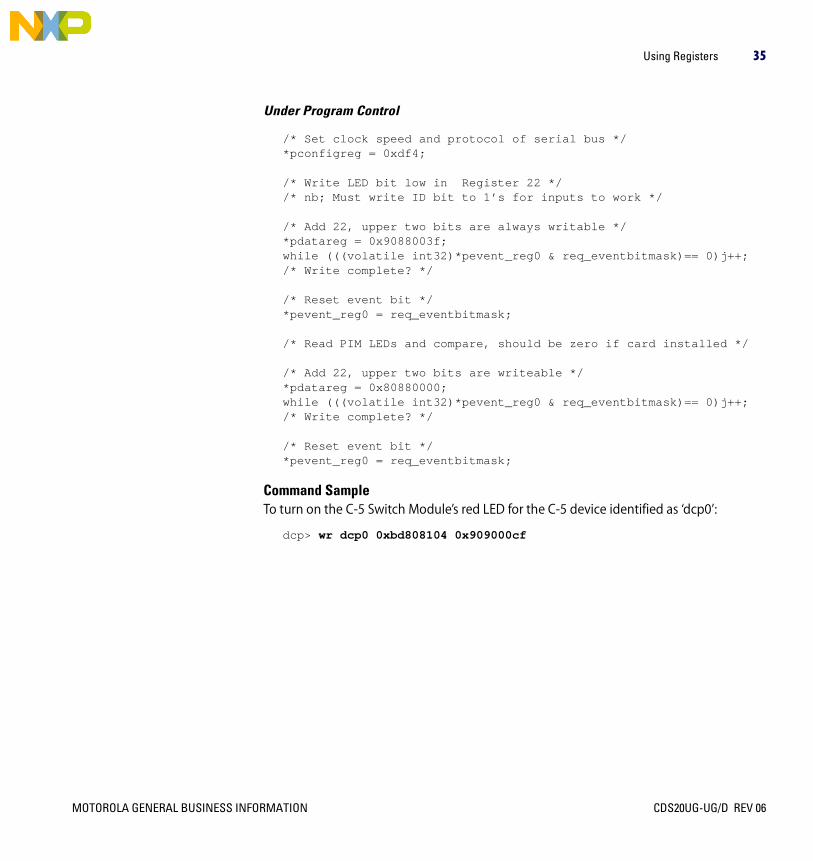
Under Program Control
/* Set clock speed and protocol of serial bus */*pconfigreg = 0xdf4;
/* Write LED bit low in Register 22 *//* nb; Must write ID bit to 1’s for inputs to work */
/* Add 22, upper two bits are always writable */*pdatareg = 0x9088003f; while (((volatile int32)*pevent_reg0 & req_eventbitmask)== 0)j++;/* Write complete? */
/* Reset event bit */*pevent_reg0 = req_eventbitmask;
/* Read PIM LEDs and compare, should be zero if card installed */
/* Add 22, upper two bits are writeable */*pdatareg = 0x80880000; while (((volatile int32)*pevent_reg0 & req_eventbitmask)== 0)j++;/* Write complete? */
/* Reset event bit */ *pevent_reg0 = req_eventbitmask;
Command SampleTo turn on the C-5 Switch Module’s red LED for the C-5 device identified as ‘dcp0’:
dcp> wr dcp0 0xbd808104 0x909000cf
MOTOROLA GENERAL BUSINESS INFORMATION CDS20UG-UG/D REV 06

36 CHAPTER 2: USING SERIAL BUS REGISTERS
C-5 Switch Module Registers
Table 10 C-5 Switch Module Register Address 24
All other register addresses are reserved.
Bit Position 7 6 5 4 3 2 1 0
Field Name Red LED Green LED PIM Installed Not Used ID 3 ID 2 ID 1 ID 0
R/W W W R - R R R R
Table 11 C-5 Switch Module Register Address 24 Field Descriptions
FIELD NAME BIT POSITION DESCRIPTION
Network Processor Module ID
3:0 C-5 Switch Module ID bits describe the type and revision of the module.C-5 Switch Module Revision B1 - 0001C-5 Switch Module Revision B2 and B4- 0010C-5 Switch Module Revision B3 - 0011C-5 Switch Module Revision B4-30 - 0101C-5 Switch Module Revision C0- 0110
PIM Installed 5 The PIM Installed bit indicates that the C-5 Switch Module has detected a PIM connected to it.Installed - 0Not installed - 1
Green LED 6 “Good” LEDOn - 0Off - 1
Red LED 7 “Error” LEDOn - 1Off - 0
CDS20UG-UG/D REV 06 MOTOROLA GENERAL BUSINESS INFORMATION

Ethernet/OC-3c/Gigabit Combo PIM Registers 37
Ethernet/OC-3c/Gigabit Combo PIM Registers
Table 12 Ethernet/OC-3c/Gigabit Combo PIM Register Address 22
Table 14 Ethernet/OC-3c/Gigabit Combo PIM Register Address 23
Bit Position 7 6 5 4 3 2 1 0
Field Name Red LED Green LED Blue LED Bus Reset ID 3 ID 2 ID 1 ID 0
R/W W W W W R R R R
Table 13 Ethernet/OC-3c/Gigabit Combo PIM Register Address 22 Field Descriptions
FIELD NAME BIT POSITION DESCRIPTION
Network Processor Module ID
3:0 PIM Module ID bits describe the type and revision of the module.Ethernet/OC-3c/Gigabit Combo PIM Revision A1 - 1111
Bus Reset 4 Two-bit serial bus RESET asserted - 0, RESET not asserted - 1
Blue LED 5 Hot Swap Ready (Not supported on this PIM)On - 0Off - 1
Green LED 6 “Good” LEDOn - 0Off - 1
Red LED 7 “Error” LEDOn - 1Off - 0
Bit Position 7 6 5 4 3 2 1 0
Field Name Not Used
Not Used
Not Used
Not Used
Not Used
Not Used
Enable Loop-Back
Port 9
Enable Comma
Detect Port 9
R/W - - - - - - W W
MOTOROLA GENERAL BUSINESS INFORMATION CDS20UG-UG/D REV 06

38 CHAPTER 2: USING SERIAL BUS REGISTERS
All other register addresses are reserved.
10/100 Ethernet PIM Registers
Table 16 10/100 Ethernet PIM Register Address 22
All other register addresses are reserved.
Table 15 Ethernet/OC-3c/Gigabit Combo PIM Register Address 23 Field Descriptions
FIELD NAME BIT POSITION DESCRIPTION
Enable Comma Detect Port 9
0 Enable -1Disable - 0
Enable Loop-Back Port 9
1 Enable -1Disable - 0
Not Used 7:2 -
Bit Position 7 6 5 4 3 2 1 0
Field Name Red LED Green LED Blue LED Bus Reset ID 3 ID 2 ID 1 ID 0
R/W W W W W R R R R
Table 17 10/100 Ethernet PIM Register Address 22 Field Descriptions
FIELD NAME BIT POSITION DESCRIPTION
Network Processor Module ID
3:0 PIM Module ID bits describe the type and revision of the module.10/100 Ethernet PIM Revision A2 - 101110/100 Ethernet PIM Revision A3 - 1011*
* Although revisions to PIMs occur the ID remains the same.
Bus Reset 4 Two-bit serial bus RESET asserted - 0, RESET not asserted - 1
Blue LED 5 Hot Swap Ready (Not supported on this PIM)On - 0Off - 1
Green LED 6 “Good” LEDOn - 0Off - 1
Red LED 7 “Error” LEDOn - 1Off - 0
CDS20UG-UG/D REV 06 MOTOROLA GENERAL BUSINESS INFORMATION

Gigabit Ethernet PIM Registers 39
Gigabit Ethernet PIM Registers
Table 18 Gigabit Ethernet PIM Register Address 22
Bit Position 7 6 5 4 3 2 1 0
Field Name Red LED Green LED Blue LED Bus Reset ID 3 ID 2 ID 1 ID 0
R/W W W W W R R R R
Table 19 Gigabit Ethernet PIM Register Address 22 Field Descriptions
FIELD NAME BIT POSITION DESCRIPTION
Network Processor Module ID
3:0 PIM Module ID bits describe the type and revision of the module.Gigabit Ethernet PIM Revision A1 - 1110
Bus Reset 4 Two-bit serial bus RESET asserted - 0, RESET not asserted - 1
Blue LED 5 Hot Swap Ready (Not supported on this PIM)On - 0Off - 1
Green LED 6 “Good” LEDOn - 0Off - 1
Red LED 7 “Error” LEDOn - 1Off - 0
MOTOROLA GENERAL BUSINESS INFORMATION CDS20UG-UG/D REV 06

40 CHAPTER 2: USING SERIAL BUS REGISTERS
Table 20 Gigabit Ethernet PIM Register Address 23
All other register addresses are reserved.
Bit Position 7 6 5 4 3 2 1 0
Field Name Not Used
Not Used
Not Used
Not Used
Enable Loop-Back
Port 2
Enable Loop-Back
Port 1
Enable Comma Detect Port 2
Enable Comma
Detect Port 1
R/W - - - - W W W W
Table 21 Gigabit Ethernet PIM Register Address 23 Field Descriptions
FIELD NAME BIT POSITION DESCRIPTION
Enable Comma Detect Port 1
0 Enable -1Disable - 0
Enable Comma Detect Port 2
1 Enable -1Disable - 0
Enable Loop-Back Port 1
2 Enable -1Disable - 0
Enable Loop-Back Port 2
3 Enable -1Disable - 0
Not Used 7:4 -
CDS20UG-UG/D REV 06 MOTOROLA GENERAL BUSINESS INFORMATION

OC-3c PIM Registers 41
OC-3c PIM Registers Table 22 OC-3c PIM Register Address 22
All other register addresses are reserved.
Bit Position 7 6 5 4 3 2 1 0
Field Name Red LED Green LED Blue LED Ejector Switch ID 3 ID 2 ID 1 ID 0
R/W W W W R R R R R
Table 23 OC-3c PIM Register Address 22 Field Descriptions
FIELD NAME BIT POSITION DESCRIPTION
Network Processor Module ID
3:0 PIM Module ID bits describe the type and revision of the module.OC-3c PIM Revision A1 - 1100
Ejector Switch 4 Sets interrupt for hot swap - hot swapping is not supported in the CDS.
Blue LED 5 Hot Swap Ready (Not supported on this PIM)On - 0Off - 1
Green LED 6 “Good” LEDOn - 0Off - 1
Red LED 7 “Error” LEDOn - 1Off - 0
MOTOROLA GENERAL BUSINESS INFORMATION CDS20UG-UG/D REV 06

42 CHAPTER 2: USING SERIAL BUS REGISTERS
OC-12c PIM Registers Table 24 OC-12c PIM Register Address 22
Bit Position 7 6 5 4 3 2 1 0
Field Name Red LED Green LED Blue LED Ejector Switch ID 3 ID 2 ID 1 ID 0
R/W W W W R R R R R
Table 25 OC-12c PIM Register Address 22 Field Descriptions
FIELD NAME BIT POSITION DESCRIPTION
Network Processor Module ID
3:0 PIM Module ID bits describe the type and revision of the module.OC-12c PIM Revision A1 - 1101OC-12c PIM Revision D0 - 1101*
* Although revisions to PIMs occur the ID remains the same.
Ejector Switch 4 Sets interrupt for hot swap - hot swapping is not supported in the CDS.
Blue LED 5 Hot Swap Ready (Not supported on this PIM)On - 0Off - 1
Green LED 6 “Good” LEDOn - 0Off - 1
Red LED 7 “Error” LEDOn - 1Off - 0
CDS20UG-UG/D REV 06 MOTOROLA GENERAL BUSINESS INFORMATION

OC-12c PIM Registers 43
Table 26 OC-12c PIM Register Address 23
All other register addresses are reserved.
Bit Position 7 6 5 4 3 2 1 0
Field Name Not Used
Not Used
Not Used
Not Used
Not Used
Not Used
Bus Reset All Ports
Enable Loop Back All Ports
R/W - - - - - - W W
Table 27 OC-12c PIM Register Address 23 Field Descriptions
FIELD NAME BIT POSITION DESCRIPTION
Enable Loop-Back All Ports
0 Enable -1Disable - 0
Bus Reset All Ports 1 Reset De-asserted - 1Reset Asserted- 0
Not Used 7:2 -
MOTOROLA GENERAL BUSINESS INFORMATION CDS20UG-UG/D REV 06

44 CHAPTER 2: USING SERIAL BUS REGISTERS
CDS20UG-UG/D REV 06 MOTOROLA GENERAL BUSINESS INFORMATION

MOTOROLA GENERAL BUSINESS INFORMATION
CDS20UG-UG/D
Rev 06
Chapter 3DEBUGGING WITH THE C-WARE DEVELOPMENT SYSTEM
Overview This chapter covers debugging with the C-Ware Development System (CDS). Topics include:
• Debugging Techniques
• Selecting a Debugging Strategy
• Using the C-Ware Debugger with a NP Device
• Debugging After a Panic Condition on a NP Device
• Debugging Host Application Programs That Interact With the C-Ware Simulator
Debugging Techniques The C-Ware Software Toolset (CST) and the Host Environment Software (HES) for the CDS enable several debugging techniques. In addition to the C-Ware Debugger, you can use
• printf()-style debugging
• Indicator debugging
• Direct access to the NP
With the exception of indicator debugging, which is a hardware-only technique, these techniques can be used with both C-Port NP devices and with the C-Ware Simulator. Each technique has advantages and disadvantages that depend, in part, on how the tools interact.
The C-Ware Debugger has the greatest amount of control when used with the C-Ware Simulator. Due to the nature of simulation, any stop of the program being debugged causes an immediate stop of the entire simulation. All processes stop every time a breakpoint or some other debugger event that stops the program occurs.
However, when used with a program running on some part of a NP device, the C-Ware Debugger has much less control over other parts of the chip. While breakpoints and
CDS20UG-UG/D REV 06

46 CHAPTER 3: DEBUGGING WITH THE C-WARE DEVELOPMENT SYSTEM
manual controls work on the program being debugged, there are many parts of the NP to which these controls do not apply, such as the Payload and Ring Buses.
For instance, the C-Ware Debugger can stop a program running on a cluster of Channel Processors for user interaction, but the rest of the NP continues to run. Debugging events on one part of a NP will always cause a loss of correlation (skid) between the cluster being debugged and the rest of the chip.
With these restrictions, many programmers prefer to use printf()-style debugging when working with NP hardware. Although there is a small performance penalty imposed by executing ksPrintf() function calls, when used with a NP device this technique has the advantage over the C-Ware Debugger of not losing process correlation.
Indicator debugging uses some of the indicators in the modules in the CDS. Indicators (LEDs) on the modules can be turned on and off under program control. See Chapter 2 for more information on using the indicators.
Direct access debugging is accomplished with the DCP Shell. Use direct access when you must read and write specific configuration registers and memory on either the C-Ware Simulator or the C-Port NP device. See “Read From NP Memory” on page 61 and “Write to NP Memory” on page 63 for more information on direct access debugging.
Selecting a Debugging Strategy
Your debugging strategy for any particular situation depends on a number of factors. Some debugging techniques are particularly suited to certain types of debugging problems. We make the following recommendations for an initial debugging strategy:
• Debug your program using the C-Ware Debugger and C-Ware Simulator until it runs as expected on the Simulator.
• Use printf()-style debugging when you move your program to NP hardware unless you have a need for the features of the C-Ware Debugger.
• Use the read and write capability of the DCP Shell as needed.
CDS20UG-UG/D REV 06 MOTOROLA GENERAL BUSINESS INFORMATION

Using the C-Ware Debugger with a NP Device 47
Using the C-Ware Debugger with a NP Device
The C-Ware Debugger User Guide contains complete information on using the C-Ware Debugger, including making connections to the C-Ware Simulator. This section describes using the C-Ware Debugger with a C-5 or C-5e NP device in the CDS environment, as shown in Figure 2.
Figure 2 C-Ware Debugger Connection to a Hardware C-Port NP
The C-Ware Debugger works for programs running on the C-5’s or C-5e’s XP and CPs. It does not work with host applications (running on the Host Application Module) or communication between host applications and C-5 or C-5e NP resident software. Use the tools that come with your host processor development system for host program debugging. For instance, Tornado® for VxWorks contains a complete debugger for use with host processor-resident programs.
NTDevelopment
System
C-5Device Driver
Application HostModule
(PowerPC SBC,VxWorks RTOS)
C-WareDebugger
Agent
C-WareDebugger
C-WareDebuggerTCP/IP on
EthernetSocket
Connection
PCI Bus
C-5SwitchModule
C-5 DCP
XP
CP 0 - 15
C-Ware Development System
MOTOROLA GENERAL BUSINESS INFORMATION CDS20UG-UG/D REV 06

48 CHAPTER 3: DEBUGGING WITH THE C-WARE DEVELOPMENT SYSTEM
To use the C-Ware Debugger with the CDS:
1 If it is not running already, start the console terminal, which can be either a (Windows® Hyperterm (or other terminal emulation software) session, or a hardware terminal with a physical connection to the CDS Host Application Module’s serial port.
2 If it is not running already, turn on the CDS.
3 At the CST development system:
– If debugging a NP’s XPRC program, start a C-Ware Debugger session. If debugging a NP’s CPRC program, start a C-Ware Debugger session for each shared IMEM target and one for each unshared IMEM target whose program you want to debug.
4 At the console terminal’s “DCP>” prompt, “packload” your application onto the NP with a debug boot flag set. For example:
DCP> packload dcp0 yourpackage.pkg 0xn00 [arg1 arg2 arg3 arg4]
Where:
– dcp0 is the identifier for a NP device with a CDS.
– yourpackage.pkg is the fully qualified path to your package, relative to the FTP root directory of the CST development system.
– 0xn00 is the debug boot flag. Valid debug boot flag values are: 0x200 for debugging an XPRC program, 0x400 for debugging the program on a CPRC cluster, and 0x600 for debugging both (multiple debugging sessions). These boot flags cause the host application program to look for signals from the C-Ware Debugger; the previously and separately started Debugger sessions themselves determine which XPRC or CPRCs on the NP are targeted for debugging when the NP starts.
– arg1 through arg4 represent up to four optional, space-delimited command-line arguments that the Host Application Module’s host application program might use. (No blankspace characters are allowed in these arguments.)
CDS20UG-UG/D REV 06 MOTOROLA GENERAL BUSINESS INFORMATION

Debugging After a Panic Condition on a NP Device 49
One of the significant differences between using the C-Ware Debugger with the C-Ware Simulator and the NP is the “load and go” nature of the ‘packload’ command. “Packloading” a host application program causes it to run (and, in turn, load the NP) as soon as it is loaded. Setting any debug boot flag embeds a breakpoint in the loaded program so that you can control its execution using the C-Ware Debugger.
You can use as many instances of the C-Ware Debugger as you have executables to debug simultaneously. See the C-Ware Debugger User Guide for information on operating the Debugger during a debugging session.
Debugging After a Panic Condition on a NP Device
If a run-time problem in your C-Ware application (as it runs on a C-5 or C-5e NP device) has caused it to call the C-Ware API ksPanic() routine, you can view output from that routine as output in the window that is served by the application’s C-Ware API ksPrintf() routine, or via a console connection to the CDS’s serial port. For instance, the output from ksPanic() displays the CpId (number of a NP Channel Processor) where the panic condition occurred.
In addition, you can use the C-Ware Debugger (that is, via the CDS’s C-Ware Host Environment Software) to attach to the loaded C-Ware application and examine the state of the offending XPRC or CPRC program while it is still loaded.
To do so:
1 Start the Debugger on your development workstation:
C:\C-Port\...\mycode\run\> cport-gdb
2 Attach this Debugger session to the C-Ware application running on the C-Port NP device identified as ‘DCP0’ and in a particular CP’s IMEM (in this case, CP1):
[In the Debugger’s console window](gdb) file \C-Port\...\mycode\run\mycode.dcp (gdb) target dcp0 imem1 mozart:2000
Important: In a scenario of attaching to a C-Ware application that has entered a panic state, after you have established a Debugger-based connection to the application, you cannot use the Debugger to continue execution of the C-Ware application.
MOTOROLA GENERAL BUSINESS INFORMATION CDS20UG-UG/D REV 06

50 CHAPTER 3: DEBUGGING WITH THE C-WARE DEVELOPMENT SYSTEM
If the call to ksPanic() occurred in the offending RC’s context 0 (that is, the RC’s interrupt context, by C-Ware convention), you can use the Debugger to determine two kinds of information:
• What behavior preceded the call to ksPanic() in the offending RC’s context 0. To answer this question, use the Debugger’s ‘backtrace’ command to unwind the context 0 stack.
• What the user code on the offending RC was doing when the exception/interrupt occurred. To answer this question, you must examine one or more of the stacks for the offending RC’s user contexts (that is, the RC’s contexts 1 to 3, by C-Ware convention).
To switch between the offending RC’s interrupt context and its other contexts, use the Debugger’s ‘uc’ and ‘ic’ commands to toggle between the RC’s interrupt context and its user contexts.
On the other hand, if the call to ksPanic() occurred in one of the RC’s user contexts, use of the Debugger’s ‘uc’ and ‘ic’ commands do nothing (that is, they act as no-ops in this particular case).
Debugging Host Application Programs That Interact With the C-Ware Simulator
During host application development, it can be useful to connect the program running on the Host Application Module to a C-Ware Simulator rather than to a C-5 or C-5e NP device. In this scenario, you make the connection between the C-Ware Debugger and C-Ware Simulator (as described in the section “Using the C-Ware Debugger with a NP Device” on page 47), then you add a connection to the host application program.
Using the C-Ware Debugger in conjunction with a debugger for your host program (such as the Tornado debugger) supports concurrent C-Port NP and host program debugging.
The C-5 Device Driver expects to find a C-Port NP device connected to the CDS’s PCI bus. The CDS Host Environment Software includes a PCI bus simulation utility, called PCIsrv, that your CST development system uses to make the connection between the C-5 Device Driver and a C-Ware Simulator and that satisfies the Driver’s PCI bus requirement. See “PCI Bus Simulation” on page 68 for information on configuring and using PCIsrv.
CDS20UG-UG/D REV 06 MOTOROLA GENERAL BUSINESS INFORMATION

Debugging Host Application Programs That Interact With the C-Ware Simulator 51
In this debugging scenario you use the C-Ware Debugger as described in the C-Ware Debugger User Guide. However, to make the connection, you must first perform the following steps:
1 Open a DOS Command window on your CST development system (where the C-Ware Debugger will run) and start PCIsrv.
C:\C-PORT\...\apps\gbeSwitch\run> pcisrv PCISRV: PCI bus simulation, server side built on Apr 27 2000 ...
2 Start a C-Ware Simulator session on the same machine:
C:\C-PORT\...\apps\gbeSwitch\run> dcpsim c5sim CST 2.1, C-5 [Rev D0] release build on Apr 15 2002 ...[Lines removed]
3 Via the telnet session on the CDS Host Application Module, use the DCP Shell ‘open’ command to open a connection between PCIsrv and the C-5 Device Driver:
DCP>open dcp0 dcptrade2 Host/driver redirector, built on Apr 15 2002 at 23:17:14 - 000c Master socket - 000d Target socket - 000e Interrupt socketMaster task start...Target task starting...Interrupt task start...
Now PCIsrv displays the following message:
PCISRV: Forwarding Thread - Registered host with 8000000 bytes
Communication between the Host Application Module and the C-Ware Simulator is now possible.
See the C-Ware Debugger User Guide for information on using the Debugger with the C-Ware Simulator.
MOTOROLA GENERAL BUSINESS INFORMATION CDS20UG-UG/D REV 06

52 CHAPTER 3: DEBUGGING WITH THE C-WARE DEVELOPMENT SYSTEM
CDS20UG-UG/D REV 06 MOTOROLA GENERAL BUSINESS INFORMATION

MOTOROLA GENERAL BUSINESS INFORMATION
CDS20UG-UG/D
Rev 06
Chapter 4USING THE DCP SHELL
Overview This chapter presents basic information about how to use the DCP Shell software that is pre-installed on the C-Ware Development System’s (CDS) Host Application Module. Topics include:
• DCP Shell Features
• DCP Shell Commands
• Test Applications
DCP Shell Features After booting, the C-Ware Development System’s (CDS) Host Application Module runs the DCP Shell, a command-line interface to other Host Environment Software provided with the C-Ware Software Toolset (CST).
This section summarizes the key features of the DCP Shell.
Command Line Editing Cursor movement — Use the keys ← → ↑ ↓ , or [ and ] to move cursor left/right, up/down.
Insert/overtype mode — Cursor is in “insert” mode for typing text.
Text deletion — Delete key deletes the character under the cursor.
Command NameAbbreviation
You can specify each DCP Shell command keyword in an abbreviated form.
Command History The command history can be accessed and edited. Use ← → ↑ ↓ , or { and } to navigate the history. The history list wraps from earliest item to most recent item.
CDS20UG-UG/D REV 06

54 CHAPTER 4: USING THE DCP SHELL
Help Features The ‘help’ command displays a short listing of available DCP Shell commands.
The command ‘help -f’ displays a “full” listing of available DCP Shell commands, where additional help per command is displayed.
Help text for a command is available by typing ‘help command_or_abbrev’. Help is displayed for all DCP Shell commands that match the specified command_or_abbrev.
DCP Shell Commands The DCP Shell supports the following commands:
• Command Syntax Summary
• Load a Package into the NP
• Load a Dynamic Load Module
• Unload a Dynamic Load Module
• Open Connection to the C-Ware Simulator
• PCI Bus Status
• Read From NP Memory
• Redirect PrintfListener Output
• Reset a NP Device
• Displaying CDS System Information
• Write to NP Memory
CDS20UG-UG/D REV 06 MOTOROLA GENERAL BUSINESS INFORMATION

DCP Shell Commands 55
Command SyntaxSummary
Output a brief summary of the syntax of all DCP Shell commands.
SyntaxcmdSyntax
ExampleDCP>open dcpSim1 TestNode DCP Console Command Syntax Summary: cmdSyntax dmaRx <dcpName> dmaTx <dcpName> help n open <dcpSimName> <hostName> packLoad <dcpName> <pkgName> <flags> redir <dcpName> console|telnet reset <dcpName> rd <dcpName> <addr> [nBytes] sysInfo <dcpName> wr <dcpName> <addr> <value>
MOTOROLA GENERAL BUSINESS INFORMATION CDS20UG-UG/D REV 06
56 CHAPTER 4: USING THE DCP SHELL
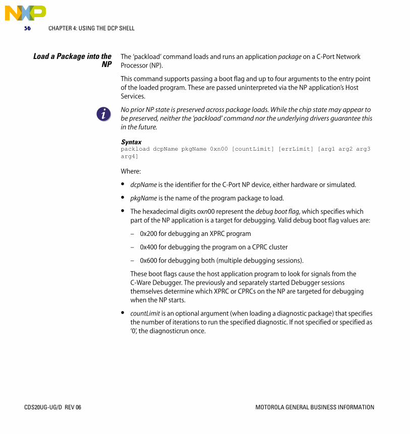
Load a Package into theNP
The ‘packload’ command loads and runs an application package on a C-Port Network Processor (NP).
This command supports passing a boot flag and up to four arguments to the entry point of the loaded program. These are passed uninterpreted via the NP application’s Host Services.
No prior NP state is preserved across package loads. While the chip state may appear to be preserved, neither the ‘packload’ command nor the underlying drivers guarantee this in the future.
Syntaxpackload dcpName pkgName 0xn00 [countLimit] [errLimit] [arg1 arg2 arg3 arg4]
Where:
• dcpName is the identifier for the C-Port NP device, either hardware or simulated.
• pkgName is the name of the program package to load.
• The hexadecimal digits oxn00 represent the debug boot flag, which specifies which part of the NP application is a target for debugging. Valid debug boot flag values are:
– 0x200 for debugging an XPRC program
– 0x400 for debugging the program on a CPRC cluster
– 0x600 for debugging both (multiple debugging sessions).
These boot flags cause the host application program to look for signals from the C-Ware Debugger. The previously and separately started Debugger sessions themselves determine which XPRC or CPRCs on the NP are targeted for debugging when the NP starts.
• countLimit is an optional argument (when loading a diagnostic package) that specifies the number of iterations to run the specified diagnostic. If not specified or specified as ‘0’, the diagnosticrun once.
CDS20UG-UG/D REV 06 MOTOROLA GENERAL BUSINESS INFORMATION

DCP Shell Commands 57
• errLimit is an optional argument (when loading a diagnostic package) that specifies the number of errors that must occur before the diagnostic would automatically stop. Each failed diagnostic sub-test increments an error counter. For each such error an appropriate message is output to the terminal. If not specified or specified as ‘0’, the diagnostic stops running after the first error is detected.
• argn is a list of up to four optional, space-delimited, command-line arguments passed to the entry point of the loaded program (no embedded blankspace characters are allowed in these arguments).
ExampleThis package load supplies both a boot flag that sets debug mode to XP programs only, and a set of command line arguments to the program:
Dcp> packload dcp0 hostSvcXpCp.pkg Resetting DCP ...Reading Package file ...Loading Package ...pipeReset:clearing fromBuf=001de0c4pipeReset:clearing toBuf=001dce44pipeReset:clearing fromBuf=001e0640pipeReset:clearing toBuf=001df3c0Pkg data at Addr 0772fb50Pkg PCI Addr = 9062fb50Pkg bootFlags = 00000000Loading package on XP ...loadPackage status = 00000000Host Server built on Jul 13 2001 at 10:12:34
MOTOROLA GENERAL BUSINESS INFORMATION CDS20UG-UG/D REV 06

58 CHAPTER 4: USING THE DCP SHELL
Load a Dynamic LoadModule
Load a Dynamic Load Module (DLM) and run it beginning at its defined “init” routine. The ‘ld’ command causes the DLM given by file_path to be loaded by RTOS. If the ‘-n’ option is not specified, the ‘ld’ command derives the DLM name (as defined in the module’s own source code) from the filename part of file_path.
After the DLM is loaded, its defined init function is automatically called and is passed up to four optional command arguments (arg_0, arg_1, arg_2, and arg_3).
All four arguments to the ‘ld’ command are defined as integer values (‘int’) in the CST’s supplied DLM interface header file. The arguments are accepted by the DLM interface’s dcpDlmLoad() routine and the dcpDlmInit type (point to function).
Information about implementing a DLM is found in the C-Ware Host Application Programming Guide document.
Syntaxld [-n module_name] <file_path> [arg_0] [arg_1] [arg_2] [arg_3]
Where:
• module_name is the module name as compiled into the binary module file itself.
• file_path is the location of the file that contains the DLM module.
• arg_n is an optional integer value argument that is passed through to the DLM’s init routine.
ExampleDCP>ld mypath\dcp_shell_extensions 1 2 3 4
CDS20UG-UG/D REV 06 MOTOROLA GENERAL BUSINESS INFORMATION
DCP Shell Commands 59
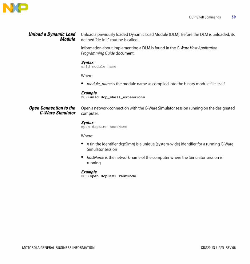
Unload a Dynamic LoadModule
Unload a previously loaded Dynamic Load Module (DLM). Before the DLM is unloaded, its defined “de-init” routine is called.
Information about implementing a DLM is found in the C-Ware Host Application Programming Guide document.
Syntaxunld module_name
Where:
• module_name is the module name as compiled into the binary module file itself.
ExampleDCP>unld dcp_shell_extensions
Open Connection to theC-Ware Simulator
Open a network connection with the C-Ware Simulator session running on the designated computer.
Syntaxopen dcpSimn hostName
Where:
• n (in the identifier dcpSimn) is a unique (system-wide) identifier for a running C-Ware Simulator session
• hostName is the network name of the computer where the Simulator session is running
ExampleDCP>open dcpSim1 TestNode
MOTOROLA GENERAL BUSINESS INFORMATION CDS20UG-UG/D REV 06

60 CHAPTER 4: USING THE DCP SHELL
PCI Bus Status Scan and display the status of the PCI buses to which the Host Application Module is attached.
SyntaxpciShow
ExampleDCP>pciShow Scanning function 0 of each PCI device on bus 0Using configuration mechanism 1bus device function vendorID deviceID class00000000 00000000 00000000 00001057 00004801 0006000000000000 0000000b 00000000 00001106 00000586 0006010000000000 0000000e 00000000 00001011 00000009 0002000000000000 00000014 00000000 00001011 00000026 00060400
Scanning function 0 of each PCI device on bus 1Using configuration mechanism 1bus device function vendorID deviceID class00000001 0000000a 00000000 00001011 00000022 0006040000000001 0000000d 00000000 00001011 00000022 00060400
Scanning function 0 of each PCI device on bus 2Using configuration mechanism 1bus device function vendorID deviceID class00000002 00000000 00000000 0000150e 00000001 00ff0000
CDS20UG-UG/D REV 06 MOTOROLA GENERAL BUSINESS INFORMATION

DCP Shell Commands 61
Read From NP Memory Read and display the specified number of bytes at the specified address in the C-Port NP’s internal memory map.
Syntaxrd dcpName addr [nByte]
Where:
• dcpName is the identifier for the C-Port NP device, either hardware or simulation
• addr is the starting address of the NP memory block to read
• nByte is the number of bytes to read. nByte defaults to 0x40
A related command n reads the next block of memory to the length previously specified in the ‘rd’ command’s nByte argument.
ExampleDCP> rd dcp0 0xbd900000 0xBD900000: 0xF94C7D44 0xA1AC6BA9 0x1B96D7BC 0xCF68DAFE0xBD900010: 0x76B90D60 0x2C2F49FF 0x37D4ABD6 0x77A3EF670xBD900020: 0x05E673D7 0xC26F1DF3 0xDB0634DA 0x03E668F20xBD900030: 0x9D3446C6 0x813EC899 0xDAEC2B85 0xFCA727FFDCP> n 0xBD900040: 0x35176D06 0x9FB99DCE 0x63A7F17F 0xCBA456E20xBD900050: 0xB97D1FFC 0x91E2F7AE 0xABA2AE17 0x165C8BAB0xBD900060: 0xF7CA701B 0x123B8E90 0x7C41FD9B 0xA32F23EA0xBD900070: 0xF9D6BA1B 0x07FD1553 0xB71927EF 0xF3A76A00
MOTOROLA GENERAL BUSINESS INFORMATION CDS20UG-UG/D REV 06

62 CHAPTER 4: USING THE DCP SHELL
Redirect PrintfListenerOutput
Use the ‘redir’ command to redirect output from the PrintfListener software component running on the host processor. The PrintfListener is part of the Host Environment Software provided as part of the CST.
Syntaxredir dcpName output
Where:
• dcpName is the identifier for the C-Port NP device, either hardware or simulation, creating the output.
• output is the location to send the output, either to the serial port console or a telnet session.
Running the ‘redir’ command without the second argument prints the redirection status.
ExamplesDCP> redir dcp0 telnet DCP> redir dcpsim1 console DCP> redir dcp0 DCP0 output set to console
PrintfListener redirection is cooperative. That is, the PrintfListener does not prevent multiple users from logging on via telnet to any of the C-Port NP devices visible to it. No password or any other kind of protection is provided.
See the CDS Getting Started Guide for information on using the CDS via telnet.
Reset a NP Device Syntaxreset dcpName
Where:
• dcpName is the identifier for the C-Port NP device, either hardware or simulation, to reset.
ExamplesDCP> reset dcp0 DCP> reset dcpSim1
You can also reset the system by pressing the reset button (RST) on the Host Application Module.
CDS20UG-UG/D REV 06 MOTOROLA GENERAL BUSINESS INFORMATION

DCP Shell Commands 63
Displaying CDS SystemInformation
SyntaxsysInfo dcpName
Where:
• dcpName is the identifier for the C-Port NP device, either hardware or simulation.
This command outputs information about the NP and the software version of certain support chips on the C-5 Switch Module or C-5e Switch Module (for example, “Lattice” refers to the software version embedded in an on-board PLD device).
ExampleDCP> sysInfo dcp0 C-5 Revision D0(1.3)Lattice Revision 0CPort Kernel Driver Version 1.7, built on Jul 12 2001 at 23:17:22
Write to NP Memory Write a longword (four-byte) value to the specified address in the NP internal memory map.
Syntaxwr dcpName addr data
Where:
• dcpName is the identifier for the NP device, either hardware or simulation.
• addr is the target address in the NP memory.
• data is the longword to write.
ExampleDCP> wr dcp0 0xbd900000 0x07FD1553
MOTOROLA GENERAL BUSINESS INFORMATION CDS20UG-UG/D REV 06
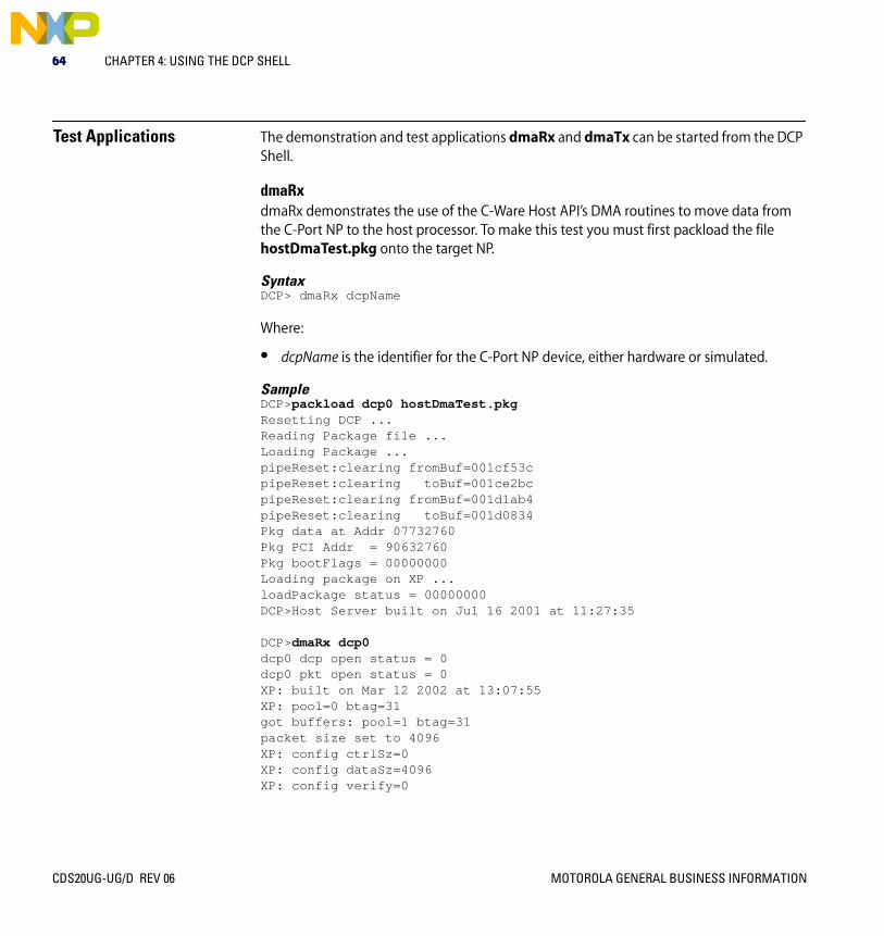
64 CHAPTER 4: USING THE DCP SHELL
Test Applications The demonstration and test applications dmaRx and dmaTx can be started from the DCP Shell.
dmaRxdmaRx demonstrates the use of the C-Ware Host API’s DMA routines to move data from the C-Port NP to the host processor. To make this test you must first packload the file hostDmaTest.pkg onto the target NP.
SyntaxDCP> dmaRx dcpName
Where:
• dcpName is the identifier for the C-Port NP device, either hardware or simulated.
SampleDCP>packload dcp0 hostDmaTest.pkg Resetting DCP ...Reading Package file ...Loading Package ...pipeReset:clearing fromBuf=001cf53cpipeReset:clearing toBuf=001ce2bcpipeReset:clearing fromBuf=001d1ab4pipeReset:clearing toBuf=001d0834Pkg data at Addr 07732760Pkg PCI Addr = 90632760Pkg bootFlags = 00000000Loading package on XP ...loadPackage status = 00000000DCP>Host Server built on Jul 16 2001 at 11:27:35
DCP>dmaRx dcp0dcp0 dcp open status = 0dcp0 pkt open status = 0XP: built on Mar 12 2002 at 13:07:55XP: pool=0 btag=31got buffers: pool=1 btag=31packet size set to 4096XP: config ctrlSz=0XP: config dataSz=4096XP: config verify=0
CDS20UG-UG/D REV 06 MOTOROLA GENERAL BUSINESS INFORMATION

Test Applications 65
// For the remainder of the listing://// In first line of each pair of lines of output:// pkt=pkt_size : Packet size that is transferred by DMA// ctrl=value : Ctrl data associated w/ the packet transfered by PIO//// In second line of each pair of lines of output:// data=value : DMA part throughput (mega bytes / sec)// ctrl=value : Control part throughput// ovhd=value : Bandwidth used by the packet xfer control protocol// rate=value : Total useful data thruput (dma + ctrl)// totl=value : Total PCI throughput (packet + ovhd)
dma pkt=4096 ctrl=0dma data=47.244095 ctrl=0.000000 ovhd=0.415231 rate=47.244095 totl=47.659326dma pkt=4096 ctrl=0dma data=47.244095 ctrl=0.000000 ovhd=0.415231 rate=47.244095 totl=47.659326dma pkt=4096 ctrl=0dma data=46.875000 ctrl=0.000000 ovhd=0.411987 rate=46.875000 totl=47.286987dma pkt=4096 ctrl=0dma data=47.244095 ctrl=0.000000 ovhd=0.415231 rate=47.244095 totl=47.659326dma pkt=4096 ctrl=0dma data=47.244095 ctrl=0.000000 ovhd=0.415231 rate=47.244095 totl=47.659326...[Lines removed]...
dmaTxdmaTx demonstrates the use of the C-Ware Host API’s DMA routines to move data from the host processor to the C-Port NP. To make this test you must first packload the file hostDmaTest.pkg onto the target NP.
SyntaxDCP> dmaTx dcpName
Where:
• dcpName is the identifier for the C-Port NP device, either hardware or simulated.
MOTOROLA GENERAL BUSINESS INFORMATION CDS20UG-UG/D REV 06

66 CHAPTER 4: USING THE DCP SHELL
CDS20UG-UG/D REV 06 MOTOROLA GENERAL BUSINESS INFORMATION
MOTOROLA GENERAL BUSINESS INFORMATION
CDS20UG-UG/D
Rev 06
Chapter 5USING HOST ENVIRONMENT SOFTWARE
Overview The C-Ware Development System’s (CDS) Host Environment software includes a number of programs designed to aid product development. These include:
• C-5 Device Driver
• PCI Bus Simulation
• Printflistener
• C-Ware Debugger Agent
C-5 Device Driver The C-5 Device Driver is a software component that allows the system’s host processor to control a given C-Port Network Processor that is part of the system. The Driver performs the following basic functions:
• Device enumeration — Automatically finds all physically connected C-5 Switch Modules or C-5e Switch modules on the PCI bus.
• Read/write interface and protocol — Enables reading from and writing to discrete memory locations on the C-Port Network Processor (NP).
• Package loading functions — Load and start software on the C-Port NP.
• Error handling and OS protection
The C-5 Device Driver is started by the CDS’s Host Application Module.
Host application programming with the C-5 Device Driver is described in the C-Ware Host Application Programming Guide document.
CDS20UG-UG/D REV 06

68 CHAPTER 5: USING HOST ENVIRONMENT SOFTWARE
PCI Bus Simulation The CDS supports host application development using the C-Ware Simulator. The C-Ware Simulator is a high-speed, performance-accurate simulator for the C-Port C-5, C-5e, and C-3e Network Processors. See the C-Ware Simulation Environment User Guide document for more information.
Since the C-5 Device Driver expects to communicate via the PCI bus, the CST includes a PCI bus simulator, named PCIsrv, for your CST development system running the C-Ware Simulator. Host applications interface to PCIsrv through the C-5 Device Driver and the C-Ware Debugger Agent software.
PCIsrv acts as a “shim” between the C-Ware Simulator, other simulated PCI bus objects, and the C-5 Device Driver. PCIsrv handles both read/write to memory and configuration, and interrupt-type bus transactions.
PCIsrv is not a timing accurate simulator. It is also not a complete PCI bus simulation; rather, it is limited to the functions needed to operate in the intended environment.
Syntaxpcisrv [options[arg]]
OptionsTable 28 PCIsrv Options
-help Shows the help screen.
-port n Port number to listen on.
-verbose Prints out all sniffed data for each device found. Without this option the program prints out a one-line summary for each device found.
CDS20UG-UG/D REV 06 MOTOROLA GENERAL BUSINESS INFORMATION

Printflistener 69
Printflistener Printflistener is a background (daemon) process that acts as a console to display ksPrintf() output from applications running on an actual C-Port NP device or on the C-Ware Simulator. ksPrintf() is a C-Ware API function that can be called from the NP’s XP and CPs.
Because Printflistener runs on the Host Application Module, you observe its output on the DCP Shell.
Printflistener is invoked on the Host Application Module at boot time.
C-Ware Debugger Agent C-Ware Debugger Agent is a background (daemon) process that runs on the CDS’s Host Application Module. It acts as a forwarding agent between a C-Ware Debugger running on your CST development workstation and the C-Port NP devices installed on any Switch Module in the CDS.
The C-Ware Debugger Agent is invoked on the Host Application Module at boot time.
See the C-Ware Debugger User Guide document for more information about C-Ware Debugger.
While it is possible to use the C-Ware Debugger Agent with the C-Ware Debugger and a simulated C-Port NP, there is no advantage to do so because the C-Ware Debugger itself communicates with C-Port NP simulations.
MOTOROLA GENERAL BUSINESS INFORMATION CDS20UG-UG/D REV 06
70 CHAPTER 5: USING HOST ENVIRONMENT SOFTWARE
CDS20UG-UG/D REV 06 MOTOROLA GENERAL BUSINESS INFORMATION

MOTOROLA GENERAL BUSINESS INFORMATION
CDS20UG-UG/D
Rev 05
Chapter 6USING DIAGNOSTICS
Overview This chapter covers how to build, load, and operate the diagnostics routine that are included with the C-Ware Development System’s (CDS) Host Environment System software. Topics include:
• About the Diagnostics
• Source Code for Diagnostics
• Object Files, Libraries, Executables, and Binaries
• Building a Diagnostics Package
• Diagnostics Packages
• Device Numbers
• Error Messages
CDS20UG-UG/D REV 05

72 CHAPTER 6: USING DIAGNOSTICS
About the Diagnostics The CST includes a set of diagnostics for the C-5 Network Processor (NP) Version D0 device and for the C-5e NP Version A1 chip under simulation.
• Diagnostics for the C-5 NP Version D0 can be performed both on the device itself and under simulation with the C-Ware Simulator (included with the C-Ware Software Toolset).
• Diagnostics for the C-5e NP Version A1 can be performed under simulation with the C-Ware Simulator.
You can use these diagnostics as-is to check the operation of the NP and associated circuits found on a C-Ware Development System’s (CDS) C-5 Switch Module board and C-5e Switch Module.
Because the C-Ware Software Toolset (CST) includes all the source code for these diagnostics, you can use the supplied code as the basis for developing your own diagnostics software.
Number and Targets forDiagnostics
There are eight “standard” diagnostic tests supported for the C-Port C-5 NP Version D0 device. The set of diagnostics is listed in the section “Diagnostics Packages” on page 84.
Each of the standard diagnostics can be built in these distinct forms, for these runtime platforms:
• C-5 NP Version D0 or C-5e Version A1 device — For an actual C-Port NP device, such as found on a C-5 Switch Module board installed in the CDS
• C-5 NP Version D0 or C-5e Version A1 under simulation — Using the CST’s C-Ware Simulator tool.
• C-5e NP Version A0 under simulation — Using the CST’s C-Ware Simulator tool.
• Acceptance Tests — Using the CST’s C-Ware Simulator tool.
CDS20UG-UG/D REV 05 MOTOROLA GENERAL BUSINESS INFORMATION

About the Diagnostics 73
One C-Ware Package FileProduced Per Diagnostic
Each diagnostic is built as its own C-Ware package file.
This means that there can be a total of 16 package files built for the entire set of standard diagnostics: 8 for hardware targets and 8 for simulation targets. (The set of Acceptance Tests use the diagnostics built for the Simulator target.)
Order for RunningDiagnostics
All the standard diagnostics utilize the NP’s BMU external memory. Therefore, we recommend that you perform the BMU_MEM standard diagnostic first. This diagnostic validates the operation of the BMU external memory.
If the BMU_MEM standard diagnostic passes, your target device can reliably load and run the other standard diagnostics.
Readme File Provided For more information, consult the Readme file found in this directory in your C-Ware Software Toolset (CST) installation:
diags\chip\doc\Readme
MOTOROLA GENERAL BUSINESS INFORMATION CDS20UG-UG/D REV 05

74 CHAPTER 6: USING DIAGNOSTICS
Source Code for Diagnostics
All Diagnostic Source files (.c or .S extension) can be found under the following paths:
• diags\chip\np\cprc\src\ and diags\chip\np\cprc\c5\src\— Source Code for Channel Processor RISC Core (CPRC)
• diags\chip\np\xprc\src\ — Source Code for Executive Processor RISC Core (XPRC)
• diags\chip\np\sdp\src\ — Source Code for the Channel Processor Serial Data Processors (SDP)
• diags\chip\np\fdp\src\ — Source Code for the Fabric Processor’s FDPs (Fabric Data Processors)
• diags\chip\np\src\ — Source Code that is common to XPRC and CPRC
Corresponding header files (*.h) are found at each of these levels also, as follows:
• diags\chip\np\inc\
• diags\chip\np\cprc\inc\
• diags\chip\np\xprc\inc\
• diags\chip\np\sdp\inc\
• diags\chip\np\fdp\inc\
CDS20UG-UG/D REV 05 MOTOROLA GENERAL BUSINESS INFORMATION

Object Files, Libraries, Executables, and Binaries 75
Object Files, Libraries, Executables, and Binaries
For background, consult the Build System Conventions document in the CST documentation set.
The derived object files based on Diagnostic source files are stored in subdirectories in the format diags\chip\XXX\run\, where XXX is the name of the diagnostic test as listed in Table 30 on page 84.
MOTOROLA GENERAL BUSINESS INFORMATION CDS20UG-UG/D REV 05

76 CHAPTER 6: USING DIAGNOSTICS
Building a Diagnostics Package
The following sections provide detailed information on building diagnostics packages for hardware targets and simulation targets.
Custom Diagnostics MakeTargets
The single gnu-compatible make file (named Makefile) provided for building all diagnostics supports the build targets provided by the CST’s build system. See the Build System Conventions document to learn about the CST’s build system.
Here is a brief list of case-sensitive build_target identifiers that specifically pertain to diagnostics packages:
• all — Builds all 7 standard diagnostics for simulation and hardware targets, depending on the CST environment variable settings. all is the default build-target.
• clean_diags — Deletes all binary files (.obj, .a, .lib, .dcp, .pkg, etc.) for all targets (BMU, TLU, etc.) for the current variant (for example, c5e-a1-hw-debug).
• help — Displays an extensive list of information for all make targets.
• hwstd — Builds all 8 standard diagnostics for a hardware target (same as make all, but the CPORT_TGT environment variable is over-ridden to hw).
• simstd — Builds all 8 standard diagnostics for a simulation target (same as make all, but the CPORT_TGT environment variable is over-ridden to sim).
The term “variant” (for example, c5-d0-sim-debug) and its relation to CST environment variables (CPORT_TGT, etc.) is described in the Build System Conventions document.
Building the StandardDiagnostics
From the directory diags\chip\run, the following command:
make hwstd
causes the 8 “standard” diagnostics package files to be created for a hardware target.
Each diagnostics package file that is built is placed under the diags\chip directory tree.
CDS20UG-UG/D REV 05 MOTOROLA GENERAL BUSINESS INFORMATION

Building a Diagnostics Package 77
Location of Diagnostic PackagesAfter building any diagnostic, all of its files are stored in the directory;
diags\chip\XXX\run\bin\variant
Where:
– XXX is the name of the diagnostic test. See Table 30 for the complete list.
– variant represents the build target variant as determined by the settings of the CST environment variables at the time you performed the build. For example, one variant is c5e-a1-hw-debug.
The general format for diagnostic packages is as follows:
diags\chip\XXX\run\bin\c5e-b0-hw-debug\XXX.pkg
The BMU_MEM diagnostic package is located at:
diags\chip\BMU_MEM\run\bin\c5-d0-hw-debug\BMU_MEM.pkg
Building Diagnostics forIndividual Targets
To build a single diagnostic package file (the ’target’), do the following:
D:\...\diags\chip\XXX\run> make
This will build the diagnostic XXX.pkg (See Table 30) for a hardware target that is determined by the current settings of the CST’s environment variables.
Building and RunningDiagnostics for Hardware
Targets
Diagnostics are grouped in package files that are loaded onto the NP device (such as found on the CDS’s C-5e Switch Module) using the DCP Shell’s 'packload' command.
See Chapter 4 for information about the DCP Shell and about the ‘packload’ command.
To build the diagnostic:
1 Open a new command window or command shell process.
2 Run the CST’s ‘sv’ script, to set the CST’s environment variables.
3 Explicitly set the CST’s environment variables for the build variant that you are about to build.
MOTOROLA GENERAL BUSINESS INFORMATION CDS20UG-UG/D REV 05

78 CHAPTER 6: USING DIAGNOSTICS
4 Change current directory to the diags\chip\XXX\run\ directory, where XXX is the name of the diagnostic. See Table 30.
5 Enter the command:
D:\...\diags\chip\XXX\run> make
To run the diagnostic:
1 After ensuring that your CDS is running, establish a terminal session with the CDS’s Host Application Module and start the DCP Shell.
2 At the DCP Shell prompt, packload the diagnostic package as follows:
Dcp> packload dcp0 XXX.pkg 0x000 1 100
Where:
– 'dcp0' is the identifier for the C-Port NP device that resides on the target CDS Host Application Module.
– ‘XXX.pkg’ is an example of a fully qualified path for the package to load, expressed as relative to the FTP root. If necessary, move the compiled diagnostic package via FTP to a directory on the CDS that is visible to VxWorks.
– The hexadecimal value ‘0x000’ specifies the debug_bootflag to use for the normal hardware diagnostic. Alternatively, enter ‘0x400’ when debugging the XPRC or ‘0x200’ when debugging the CPRCs.
– The decimal integer ‘1’ specifies an optional count_limit, or the number of iterations to run the specified diagnostic. If not specified or specified as ‘0’, causes the diagnostic to run only once. (Use of this ‘packload’ command argument is unique to running the standard diagnostics.)
– The decimal integer ‘100’ specifies an optional error_limit, or the number of errors that must occur before the diagnostic would automatically stop. If not specified or specified as ‘0’, the diagnostic stops running after the first error is detected. (Use of this ‘packload’ command argument is unique to running the standard diagnostics.)
Each package produces various outputs, but they all complete with output of "TEST RESULTS: ALL TESTS PASSED!" or "TEST RESULTS: SOME TESTS FAILED!".
CDS20UG-UG/D REV 05 MOTOROLA GENERAL BUSINESS INFORMATION

Building a Diagnostics Package 79
Building and RunningDiagnostics for Simulation
Targets
When running any standard diagnostic under the C-Ware Simulator, you must launch the Simulator also from the CST’s diags\chip\XXX\run\ directory.
To build the diagnostic for simulation, using BMU_MEM as an example:
1 Open a new command window or command shell process.
2 Run the CST’s ‘sv’ script, to set the CST’s environment variables.
3 Explicitly set the CST’s environment variables for the build variant that you are about to run under the Simulator.
4 Change current directory to the diags\chip\BMU_MEM\run\ directory.
5 Enter this command:
D:\...\diags\chip\BMU_MEM\run> make
After building the diagnostic, all its files are stored in this directory:
diags\chip\BMU_MEM\run\bin\variant
Where:
– variant represents the build target variant, as determined by the settings of the CST environment variables at the time you performed the build. For example, one build variant is c5e-a1-sim-debug.
MOTOROLA GENERAL BUSINESS INFORMATION CDS20UG-UG/D REV 05

80 CHAPTER 6: USING DIAGNOSTICS
To run the diagnostic under the C-Ware Simulator:
1 If using a diagnostic that was built using a command shell session that is now closed:
a Open a new command window or command shell process.
b Run the CST’s ‘sv’ script, to set the CST’s environment variables.
c Explicitly set the CST’s environment variables for the build variant that you are about to run under the Simulator.
2 Change current directory to diags\chip\BMU_MEM\run\
3 Start the Simulator by entering a command like this (starting at this folder):
D:\...\diags\chip\run> make run
Be sure that the CST environment variable CPORT_TGT is set to “sim”.
4 In the Simulator enter this command:
Dcp> g
Expected output will finish with "TEST RESULTS: ALL TESTS PASSED!"
Running diagnostics on the C-Ware Simulator generates many warning messages. These warnings can be ignored.
CDS20UG-UG/D REV 05 MOTOROLA GENERAL BUSINESS INFORMATION

Building a Diagnostics Package 81
Building and RunningDiagnostics for
Acceptance Test Targets
Specifying the build target ‘accept’ will in build one or more diagnostics for a simulation target, even if those diagnostics’ package files already exist. See the section “Building and Running Diagnostics for Simulation Targets” on page 79.
The ‘accept’ test is an automatic operation, only one command is needed for each diagnostic package. It must be invoked from the diags\chip\XXX\run\ directory:
Be sure the correct CST environment variables (CPORT_TGT=sim, for example) are set.
The diagnostic package target BMU_MEM is again used in following example for the accept test.
To run the accept test for BMU_MEM enter the following command:
D:\...\diags\chip\run> make accept
This command causes the ‘sim’ target to be built. After the diagnostic’s package file is built, the C-Ware Simulator is immediately invoked, and the Simulator loads and runs that package file.
Two output files are generated and stored in diags\chip\BMU_MEM\run\ for the user to review:
• diags\chip\run\sim\BMU_MEM.raw — Copy of the console message output from the Simulator.
• diags\chip\BMU_MEM\run\sim\BMU_MEM.out — Copy of the specific console message used by 'accept' to determine if the test passed or failed.
If the diagnostic passes, the Simulator console displays the message: "TEST RESULTS: ALL TESTS PASSED!"
Makefile for Diagnostics Information on compiling the diagnostics for all supported build targets is contained in the Makefile for diagnostics, located in the following directory:
diags\chip\run\
Support files for diagnostics are located in these files:
diags\chip\common\diags-base.mk — Sets variables to support the general purpose CST rules in cport-rules.mk, etc. (See Build System Conventions document.)
diags\chip\common\diags-rules.mk — Contains specific rules for diagnostics.
MOTOROLA GENERAL BUSINESS INFORMATION CDS20UG-UG/D REV 05
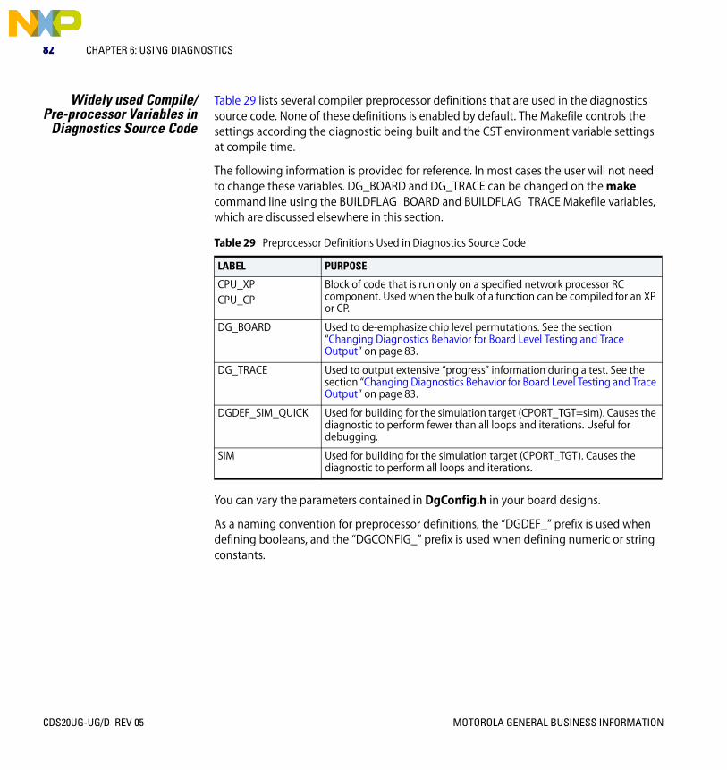
82 CHAPTER 6: USING DIAGNOSTICS
Widely used Compile/Pre-processor Variables in
Diagnostics Source Code
Table 29 lists several compiler preprocessor definitions that are used in the diagnostics source code. None of these definitions is enabled by default. The Makefile controls the settings according the diagnostic being built and the CST environment variable settings at compile time.
The following information is provided for reference. In most cases the user will not need to change these variables. DG_BOARD and DG_TRACE can be changed on the make command line using the BUILDFLAG_BOARD and BUILDFLAG_TRACE Makefile variables, which are discussed elsewhere in this section.
You can vary the parameters contained in DgConfig.h in your board designs.
As a naming convention for preprocessor definitions, the “DGDEF_” prefix is used when defining booleans, and the “DGCONFIG_” prefix is used when defining numeric or string constants.
Table 29 Preprocessor Definitions Used in Diagnostics Source Code
LABEL PURPOSE
CPU_XP CPU_CP
Block of code that is run only on a specified network processor RC component. Used when the bulk of a function can be compiled for an XP or CP.
DG_BOARD Used to de-emphasize chip level permutations. See the section “Changing Diagnostics Behavior for Board Level Testing and Trace Output” on page 83.
DG_TRACE Used to output extensive “progress” information during a test. See the section “Changing Diagnostics Behavior for Board Level Testing and Trace Output” on page 83.
DGDEF_SIM_QUICK Used for building for the simulation target (CPORT_TGT=sim). Causes the diagnostic to perform fewer than all loops and iterations. Useful for debugging.
SIM Used for building for the simulation target (CPORT_TGT). Causes the diagnostic to perform all loops and iterations.
CDS20UG-UG/D REV 05 MOTOROLA GENERAL BUSINESS INFORMATION
Building a Diagnostics Package 83
Changing DiagnosticsBehavior for Board LevelTesting and Trace Output
The DG_BOARD and DG_TRACE preprocessor definitions can be used to change the extent or behavior of a diagnostic. They are most useful when running the memory tests BMU_MEM, QMU_MEM, and TLU_MEM. The definitions can be used separately or in combination, as described in the following sections.
DG_BOARD This definition "optimizes" the operation of the diagnostic to be used as a board-level test. The code compiled using the default configuration of the diagnostics is suitable for testing many internal functions of the C-5 NP as well as the entire circuit board, such as for the CDS’s C-5 Switch Module. In a board-level environment, it is not necessary to exercise the many permutations of the C-5 NP internal control structures because these differences are not discernible external to the chip. The result is what would appear to be a board-level test running through the same external addresses and data sequences several times over. In addition to limiting the range of the C-5 NP internal parameters, when ’DG_BOARD’ is defined, read/write transfers are limited to a single "data line" or beat, to help in development and fault isolation.
To set DG_BOARD from the make command line:
D:\...\diags\chip\BMU_MEM\run> make BUILDFLAG_BOARD=1
DG_TRACE This definition causes the diagnostic to print out extensive ’progress’ information as it runs. The output contains specific information about exactly where and what the diagnostic is doing. It is useful as a learning tool for following the diagnostic’s flow.
To set DG_TRACE from the make command line:
D:\...\diags\chip\BMU_MEM\run> make BUILDFLAG_TRACE=1
These Makefile variables in turn are used to change the definition of associated pre-processor variables. The user should be aware that gnu-make does not recompile a source file if a preprocessor definition has been externally changed (that is, via the Makefile) as this action does not affect the date/time aspects of the source file itself. You must delete the intended object file by an explicit ‘del’ or ‘rm’ command, or by using the “clean” make targets.
MOTOROLA GENERAL BUSINESS INFORMATION CDS20UG-UG/D REV 05

84 CHAPTER 6: USING DIAGNOSTICS
Diagnostics Packages Table 30 lists the “standard set” of diagnostics for the C-5 and C-5e NPs.
Table 30 C-5 Network Processor “Standard” Diagnostic Packages
DIAGNOSTIC DESCRIPTION
BMU_MEM BMU register test from XP and CPs
BMU memory test - power-2 locations mapped via PoolId, BTag, and offset. Tested from XP.
BMU BMU register test from CPs
BMU functional test.
GLOBALBUS Gbus Slave Wait Test – CP Slave
Gbus Slave Release Test – CP Master
QMU_MEM XP Quick memory tests of internal QMU memories and some QMU registers.
XP Quick memory test of external QMU memory via diagnostic hardware interface.
XP test to check parity logic for parity bits by forcing parity and detecting errors on the dequeued descriptors. This test uses the external SRAM.
XP test to check parity logic for parity bits for all descriptors using the special hardware loopback feature.
XP Quick memory tests of internal QMU memories and some QMU registers.
XP Quick memory test of external QMU memory via diagnostic hardware interface.
XP test to check parity logic for parity bits by forcing parity and detecting errors on the dequeued descriptors. This test uses the external SRAM.
XP test to check parity logic for parity bits for all descriptors using the special hardware loopback feature.
For each descriptor size, single queue/dequeue test with walking 1s across weight and descriptor fields. This is done from the XP as well as the CPs’ perspective.
CP test to check parity logic for parity bits by forcing parity and detecting errors on the dequeued descriptors. This test uses the external SRAM.
CP test to check parity logic for parity bits for all descriptors using the special hardware loopback feature.
CDS20UG-UG/D REV 05 MOTOROLA GENERAL BUSINESS INFORMATION

Diagnostics Packages 85
RINGBUS Single-slot message/response passed around Ring Bus – repeated for walking 1s & 0s, all 1s & 0s. This is done from the XP as well as the CPs’ perspective.
Extension of singles-slot test for multiple-slot. This is done from the XP as well as the CPs’ perspective.
Tests sequence numbers of consecutive slots of a multi-slot message. This is done from the XP as well as the CPs’ perspective.
Tests all receive-message and receive-response registers for collisions – 2 or more messages destined for the same set of receive registers. This is done from the XP as well as the CPs’ perspective.
Tests full Ring Bus conditions. Full from a single node’s perspective. This is done from the XP as well as the CPs’ perspective.
SDPCSAddrBus Using special microcode, tests the address lines of the microsequencer control stores on all CPs.
TIMERS Tests the system cycle counter to make sure it is ticking. This is done from the XP as well as the CPs’ perspective.
Tests the system event timer to make sure it ticks and will set corresponding event bit. This is done from the XP as well as the CPs’ perspective.
TLU_MEM Tests single-slot echo – data paths in and out of the TLU via the Ring Bus for single-slot messages. This is done from the XP as well as the CPs’ perspective.
XP test to check the read/writeable TLU registers.
BMU memory test, power-2 locations mapped via table and entry. Tested from XP.
Table 30 C-5 Network Processor “Standard” Diagnostic Packages (continued)
DIAGNOSTIC DESCRIPTION
MOTOROLA GENERAL BUSINESS INFORMATION CDS20UG-UG/D REV 05

86 CHAPTER 6: USING DIAGNOSTICS
Device Numbers The device numbers listed in Table 31 are reported in diagnostics error messages.
Table 31 Diagnostics Device Numbers
DEVICEDEVICE NUMBER DESCRIPTION
DGDEV_DUMMY 0xFFFFFFFF Used for internal testing
DGDEV_NONE 0x1
DGDEV_XPRC 0x2 RISC core of XP
DGDEV_CPRC 0x3 RISC core of CP
DGDEV_XP_DMEM24 0x4
DGDEV_XP_DMEM25 0x5
DGDEV_CP_DMEM 0x6
DGDEV_RING_BUS 0x7
DGDEV_PAYLOAD_BUS 0x8
DGDEV_CP_AREAS 0x9 CP Memories
DGDEV_XP_AREAS 0xA XP Global Access Areas
DGDEV_QMU 0x10 General QMU
DGDEV_QMU_MEM 0x11 QMU memory, generic
DGDEV_QMU_DESC_LINK_MEM
0x11 QMU memory
DGDEV_QMU_DESC_IS_DYN_MEM
0x12 QMU memory
DGDEV_QMU_DESC_WEIGHT_MEM
0x13 QMU memory
DGDEV_QMU_HEAD_TAIL_MEM
0x14 QMU memory
DGDEV_QMU_LENGTH_MEM
0x15 QMU memory
DGDEV_QMU_WEIGHT_MEM
0x16 QMU memory
DGDEV_QMU_PARAM_MEM 0x17 QMU memory
DGDEV_QMU_FREE_DESC_LIST_HEAD_REG
0x18 QMU memory
CDS20UG-UG/D REV 05 MOTOROLA GENERAL BUSINESS INFORMATION

Device Numbers 87
DGDEV_QMU_FREE_DESC_LIST_TAIL_REG
0x19 QMU memory
DGDEV_QMU_FREE_DESC_LIST_LENGTH_REG
0x1A QMU memory
DGDEV_QMU_DYN_POOL_0_USAGE_REG
0x1B QMU memory
DGDEV_QMU_DYN_POOL_1_USAGE_REG
0x1C QMU memory
DGDEV_QMU_DYN_POOL_2_USAGE_REG
0x1D QMU memory
DGDEV_QMU_DYN_POOL_3_USAGE_REG
0x1E QMU memory
DGDEV_QMU_EXT_SRAM 0x1F QMU memory
DGDEV_QMU_MC_DESTIN_RAM
0x20 QMU multicast memory (144 x 7)
DGDEV_TLU_REG 0x40 TLU registers
DGDEV_TLU_ECHO 0x41 TLU echo operation
DGDEV_TLU_MEM 0x42 TLU memory
DGDEV_SDP 0x50 SDP
DGDEV_BMU_REG 0x60 BMU registers
DGDEV_BMU_MEM 0x61 BMU memory
DGDEV_CP_XP_GBUS 0x70 Gbus interface between XP and CPs
DGDEV_ENET 0x80 Ethernet devices
Table 31 Diagnostics Device Numbers (continued)
DEVICEDEVICE NUMBER DESCRIPTION
MOTOROLA GENERAL BUSINESS INFORMATION CDS20UG-UG/D REV 05
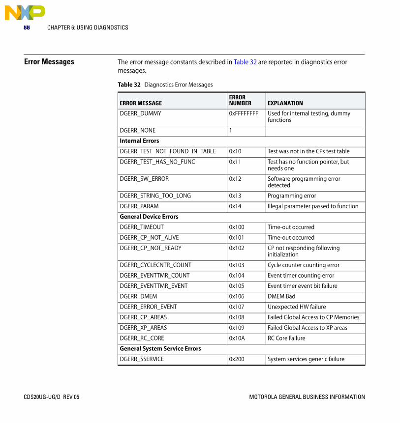
88 CHAPTER 6: USING DIAGNOSTICS
Error Messages The error message constants described in Table 32 are reported in diagnostics error messages.
Table 32 Diagnostics Error Messages
ERROR MESSAGEERROR NUMBER EXPLANATION
DGERR_DUMMY 0xFFFFFFFF Used for internal testing, dummy functions
DGERR_NONE 1
Internal Errors
DGERR_TEST_NOT_FOUND_IN_TABLE 0x10 Test was not in the CPs test table
DGERR_TEST_HAS_NO_FUNC 0x11 Test has no function pointer, but needs one
DGERR_SW_ERROR 0x12 Software programming error detected
DGERR_STRING_TOO_LONG 0x13 Programming error
DGERR_PARAM 0x14 Illegal parameter passed to function
General Device Errors
DGERR_TIMEOUT 0x100 Time-out occurred
DGERR_CP_NOT_ALIVE 0x101 Time-out occurred
DGERR_CP_NOT_READY 0x102 CP not responding following initialization
DGERR_CYCLECNTR_COUNT 0x103 Cycle counter counting error
DGERR_EVENTTMR_COUNT 0x104 Event timer counting error
DGERR_EVENTTMR_EVENT 0x105 Event timer event bit failure
DGERR_DMEM 0x106 DMEM Bad
DGERR_ERROR_EVENT 0x107 Unexpected HW failure
DGERR_CP_AREAS 0x108 Failed Global Access to CP Memories
DGERR_XP_AREAS 0x109 Failed Global Access to XP areas
DGERR_RC_CORE 0x10A RC Core Failure
General System Service Errors
DGERR_SSERVICE 0x200 System services generic failure
CDS20UG-UG/D REV 05 MOTOROLA GENERAL BUSINESS INFORMATION

Error Messages 89
Ring Bus Errors
DGERR_RB_TXFAIL 0x301 Transmit failed
DGERR_RB_RXFAIL 0x302 Receive failed
DGERR_RB_MSGPKTCNTRLFAIL 0x303 Message packet failed, control portion of the packet received unexpected value
DGERR_RB_RSPPKTCNTRLFAIL 0x304 Response packet failed, control portion of the packet received unexpected value
DGERR_RB_MSGPKTDATAFAIL 0x305 Message packet failed, data portion of the packet received unexpected value
DGERR_RB_RSPPKTDATAFAIL 0x306 Response packet failed, data portion of the packet received unexpected value
DGERR_RB_SATURATION 0x307 Ring Bus failed to saturate as expected
DGERR_RB_COLLISION 0x308 Ring Bus failed during collision test
QMU Errors
DGERR_QMU_INTERNAL_MEM 0x401 One of the internal memories failed
DGERR_QMU_EXTERNAL_SRAM 0x402 External QMU SRAM failed
DGERR_QMU_SEND_TIMEOUT 0x403 Time-out waiting to be able to send a message
DGERR_QMU_STATUS 0x404 Status on queue is not what was expected
DGERR_QMU_NO_RCV 0x405 Did not receive a message
DGERR_QMU_BAD_RCV 0x406 Did not receive a message that was sent
DGERR_QMU_PARITY 0x407 Parity error logic not correct
DGERR_QMU_CONFIG 0x408 Could not configure the QMU as expected
Table 32 Diagnostics Error Messages (continued)
ERROR MESSAGEERROR NUMBER EXPLANATION
MOTOROLA GENERAL BUSINESS INFORMATION CDS20UG-UG/D REV 05

90 CHAPTER 6: USING DIAGNOSTICS
TLU Errors
DGERR_TLU_REG 0x501 Register test failed
DGERR_TLU_REG_WRITE 0x502 Writing to register failed
DGERR_TLU_REG_READ 0x503 Reading from register failed
DGERR_TLU_ECHO_TXFAIL 0x504 Transmitting echo Ring Bus packet failed
DGERR_TLU_ECHO_RXFAIL 0x505 Receiving echo from TLU from Ring Bus packet failed
DGERR_TLU_ECHO_RSPPKTCNTRLFAIL 0x506 Received echoed packet control not what was expected
DGERR_TLU_ECHO_RSPPKTDATAFAIL 0x507 Received echoed packet data not what was expected
DGERR_TLU_TBL_WRITE 0x508 Writing table entry failed
DGERR_TLU_TBL_READ 0x509 Reading table entry failed
DGERR_TLU_TBL_MEM 0x50A Table memory failure
SDP Errors
DGERR_SDP 0x601 SDP failed
BMU Errors
DGERR_BMU_REG 0x701 Register test failed
DGERR_BMU_MEM 0x702 BMU memory test failed
Payload Bus Errors
DGERR_PLB_WRITE_FAIL 0x801 Writing across payload bus failed
DGERR_PLB_READ_FAIL 0x802 Reading across payload bus failed
Global Bus Errors
DGERR_GBUS_CP_XP_FAIL 0x900 CP/XP Gbus failure
DGERR_GBUS_TIMEOUT 0x901 Gbus failure, master/slave CP did not respond
Table 32 Diagnostics Error Messages (continued)
ERROR MESSAGEERROR NUMBER EXPLANATION
CDS20UG-UG/D REV 05 MOTOROLA GENERAL BUSINESS INFORMATION

MOTOROLA GENERAL BUSINESS INFORMATION
CDS20UG-UG/D
Rev 06
INDEX
Symbols10/100 Ethernet PIM board
registers 38
CC-5 Simulator 47C-5 Switch Module board
registers 36switch settings 26
CDS modulesidentification bits, in 34
Channel Processor (CP) 47circuit breaker 24cmdSyntax command 55Combo PIM board
registers 37continue reading from an address on the NP 61controls and indicators
for C-Ware Development System 25C-Ware Debugger 47, 49C-Ware Debugger Agent software 69C-Ware Development System (CDS)
controls and indicators 25startup 24support software 24troubleshooting tips 30using with external test equipment 29using without a C-5 Switch Module 29warranty and liability limitations 31
Ddc on/off switch 24DCP Shell commands 53
cndSyntax command 55ld 58n 61open 59packload 56pciShow 60rd 61redir 62reset 62running test applications 64syntax summary 55sysInfo 63unld 59wr 63
debug boot flag 48, 48detecting ksPrintf() output from the NP 69developing host application programs 31device numbers
reported in diagnostic test error messages 86diagnostics
device numbers reported in error messages 86error message constants 88list of packages 84
displaying CDS system information 63displaying PCI bus status 60displaying syntax of all DCP Shell commands 55dmaRx test application 64dmaTx test application 64
CDS20UG-UG/D REV 06

92 INDEX
Eerror messages
constants reported by diagnostic tests 88Executive Processor (XP) 47external test equipment
using with the C-Ware Development System 29
Fforwarding data to and from the C-Ware Debugger 69
GGigabit Ethernet PIM board
registers 39
Hhost applications
development of 31hostDmaTest.pkg file 64, 65
Iidentification bits
in CDS modules 34
KksPrintf() routine 69
Lld command 58load a Dynamic Load Module 58loading a package into a NP 48loading a packing into a NP 56
MMDIO 34
CDS20UG-UG/D REV 06
Nn command 61
OOC-12c PIM board
registers 42OC-3c PIM board
registers 41open command 59open connection to the C-Ware Simulator 59
Ppackload command 48, 56PCI bus simulation 68pciShow command 60PCIsrv utility 68Physical Interface Module (PIM) 33PrintfListener utility 69programmable logic device (PLD) 33
Rrd command 61reading from an address on the NP 61redir command 62redirecting PrintfListener output 62reset command 62resetting a NP 62
Sserial bus registers
using 34simulating the PCI bus 68sysInfo command 63
MOTOROLA GENERAL BUSINESS INFORMATION

INDEX 93
Ttest applications
running from DCP Shell 64troubleshooting the C-Ware Development System 30two-bit serial bus 34
Uunld command 59unload a Dynamic Load Module 59using the C-Ware Debugger with a C-5 device 47
Wwarranty and liability limitations
for C-Ware Development System 31Windows® Hyperterm 48wr command 63writing a longword value to an address on the NP 63
MOTOROLA GENERAL BUSINESS INFORMATION
CDS20UG-UG/D REV 06
94 INDEX
CDS20UG-UG/D REV 06
MOTOROLA GENERAL BUSINESS INFORMATION

Motorola, Inc. C-Port Family of Network Processors 120 Water Street, No. Andover, MA 01845 Voice: (978) 773-2300 FAX: (978) 773-2301


