Use of FTDI devices in life support and/or safety applications is entirely at the user’s risk, and the user agrees to defend, indemnify and hold harmless FTDI from any and all damages, claims, suits or expense resulting
from such use.
Future Technology Devices International Limited (FTDI) Unit 1, 2 Seaward Place, Glasgow G41 1HH, United Kingdom Tel.: +44 (0) 141 429 2777 Fax: + 44 (0) 141 429 2758
This application note demonstrates controlling an LED backlight over a USB connection utilizing the FTDI C232HM cable. The cable contains the FTDI FT232H IC and the LED backlight controller is the Maxim MAX17061 IC. The libMPSSE-I2C library is used in a Microsoft Visual Studio C++ console application that controls the FT232H which, in turn, sends commands over a SMBus to the MAX17061. The MAX17061 finally controls the power to the LEDs.
The connection from the USB port to the LEDs is controlled by a console application written in Visual C++ which links to the libMPSSE library and performs the following functions:
Identify the FTDI devices and open the first C232HM cable found Initialize the SMBus Read and write the various registers of the MAX17061
Control the brightness of the LEDs that are connected to the MAX17061
1.1 Scope
This document is meant to function as an introduction to the use of the FTDI C232HM cable in conjunction with I2C and SMBus devices. Familiarity with installing the FTDI device drivers and using Microsoft Visual Studio 2010 is assumed. Users should reference the respective standards and datasheets for additional information.
1.2 I2C and SMBus background
I2C and SMBus are very similar. They are both meant to exchange information among ICs within a single system. Both operate with two signals referenced to ground. SDA is the bi-directional data signal and SCL is the synchronizing clock. Table 1.1 shows some of the major similarities and differences:
Feature I2C SMBus
Signals SDA and SCL SDA and SCL
Voltage Levels <2V to >10V 3V to 5V
Multi-device Yes Yes
Data Format 8 data bits followed by ACK 8 data bits followed by ACK
Speed 0bps through 3.4Mbps 10Kbps through 100Kbps
Addressing Fixed Fixed and Dynamic
Table 1.1 I2C & SMBus Features
The FTDI devices which contain an MPSSE (Multi-Protocol Synchronous Serial Engine) can interact with I2C and SMBus, as well as other serial protocols such as SPI and JTAG. As noted above, the C232HM cable contains the FT232H. Other FTDI MPSSE devices are the FT2232D, FT2232H and FT4232H. With slight modifications the code in this application note can be used with any of these ICs.
Several items are required to duplicate the program and results of this application note.
2.1.1 FTDI C232HM cable and D2XX Device Drivers
The C232HM-EDHSL-0 cable is used with this application note. The 5VDC power output from the cable is required for the MAX17061 evaluation board. The “flying leads” accept a 0.025” square post header on 0.1” centers. The USB end of the cable contains the FT232H necessary to carry out the MPSSE commands.
When installing the device drivers for the cable, ensure the D2XX device drivers are enabled. Microsoft
Windows device drivers install with both D2XX and VCP drivers enabled by default. A Linux version of the libMPSSE libraries is also available. Within Linux, the VCP drivers may need disabled prior to installing the D2XX drivers. Refer to the device driver installation guides on the FTDI Website.
2.1.2 MAX17061 EVALUATION KIT+
The MAX17061 EVALUATION KIT+ (hereafter referred to as the MAX17061 board) is an evaluation board with the MAX17061 IC, power supply circuitry, 40 white LEDs and an interface connector.
2.1.3 Power Supply
A power supply capable of generating 12VDC at a minimum of 500mA is used as a power source for the
LEDs.
2.1.4 Source Code , Compiler and Executable
The program explained within this application note can be downloaded from the following location
The source code is written within the Microsoft Visual Studio 2010 development environment. Download and extract the files to a folder on the system hard drive. A compiled executable is also included in this download.
Note that the software and source code is provided as an example only and is not guaranteed or supported by FTDI.
2.1.5 Libraries and Device Drivers
The example program relies on the FTDI D2XX Device Driver and libMPSSE-I2C library. Download and extract the ZIP file contents to folders on the host system hard drive. The necessary files are also contained with the source code for this application note.
2.1.6 Additional items
A pair of wires for connection to the power supply
Two 0603-size surface-mount 3.3KΩ resistors One 5-position 0.1” pin-header with long pins is needed. A break-away style is preferred since
1) The MAX17061 board provides locations for pull-up resistors on the SCL and SDA signals. These locations are not populated by default since the exact configuration of the SMBus is unknown.
For the purposes of this demonstration, a “middle-of-the-road” value of 3.3KΩ is chosen. Solder these two 3.3KΩ resistors in locations R8 and R9 on the MAX17061 board.
2) Solder wires to the VIN and GND tabs toward the top of the MAX17061 board. Connect these wires to the 12VDC power supply. Note that VIN is positive. Do not turn on the 12V power supply at this time.
3) Configure the MAX17061 board jumpers as noted on page 3 of its datasheet (Quick Start / Procedure).
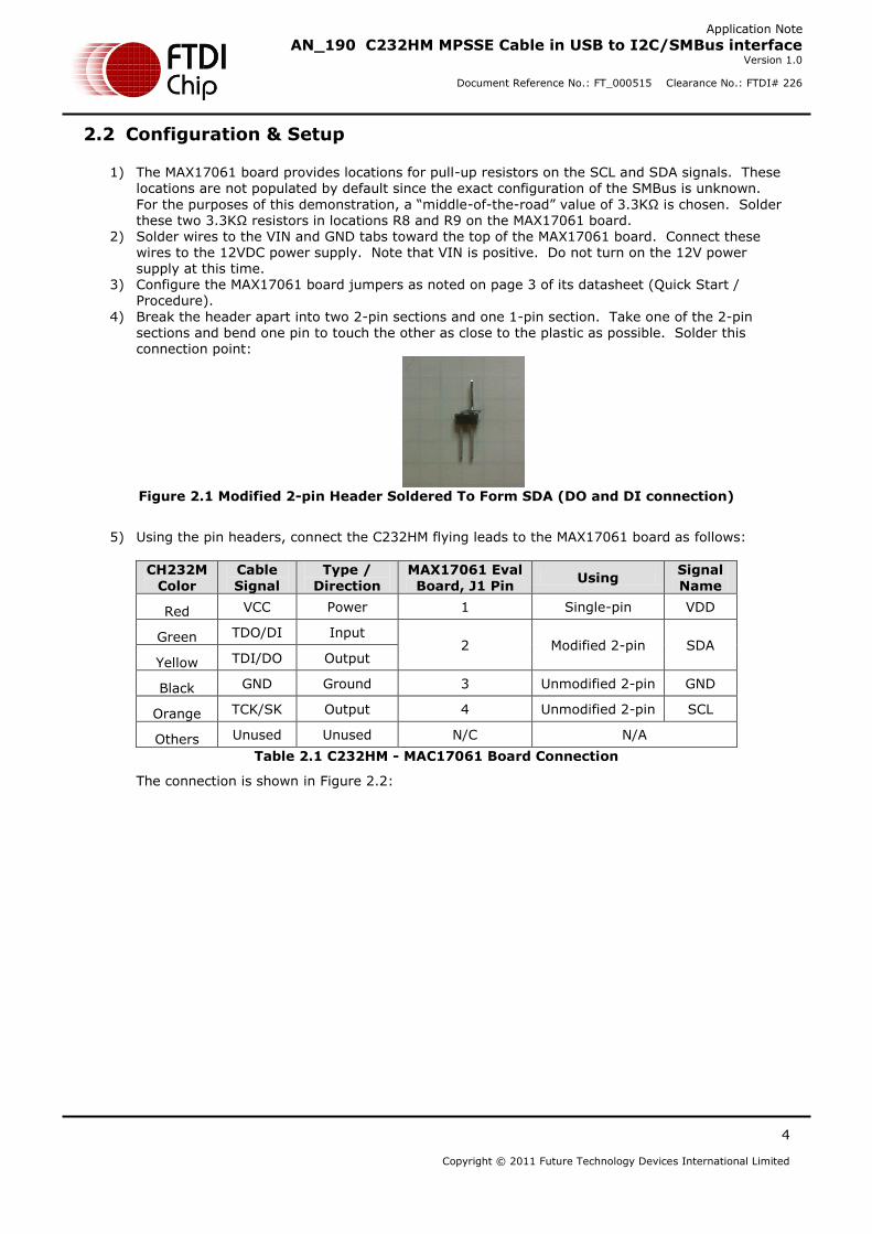
4) Break the header apart into two 2-pin sections and one 1-pin section. Take one of the 2-pin sections and bend one pin to touch the other as close to the plastic as possible. Solder this connection point:
Figure 2.1 Modified 2-pin Header Soldered To Form SDA (DO and DI connection)
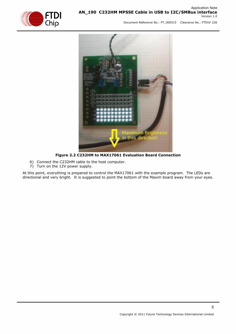
5) Using the pin headers, connect the C232HM flying leads to the MAX17061 board as follows:
Figure 2.2 C232HM to MAX17061 Evaluation Board Connection
6) Connect the C232HM cable to the host computer. 7) Turn on the 12V power supply.
At this point, everything is prepared to control the MAX17061 with the example program. The LEDs are directional and very bright. It is suggested to point the bottom of the Maxim board away from your eyes.
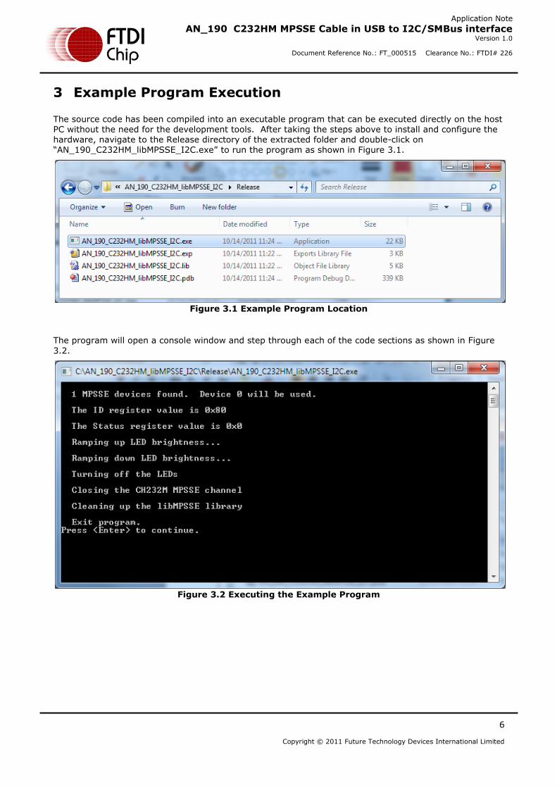
The source code has been compiled into an executable program that can be executed directly on the host PC without the need for the development tools. After taking the steps above to install and configure the hardware, navigate to the Release directory of the extracted folder and double-click on “AN_190_C232HM_libMPSSE_I2C.exe” to run the program as shown in Figure 3.1.
Figure 3.1 Example Program Location
The program will open a console window and step through each of the code sections as shown in Figure
Important aspects of the application program are discussed in the following sections.
4.1 Visual Studio 2010 Preparation
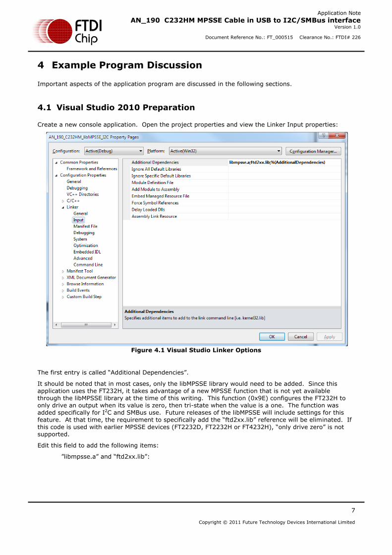
Create a new console application. Open the project properties and view the Linker Input properties:
Figure 4.1 Visual Studio Linker Options
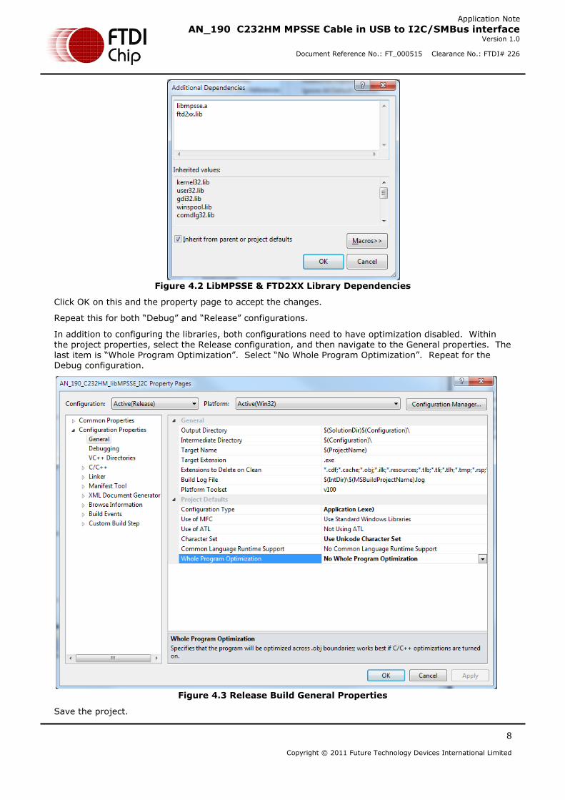
The first entry is called “Additional Dependencies”.
It should be noted that in most cases, only the libMPSSE library would need to be added. Since this application uses the FT232H, it takes advantage of a new MPSSE function that is not yet available through the libMPSSE library at the time of this writing. This function (0x9E) configures the FT232H to only drive an output when its value is zero, then tri-state when the value is a one. The function was added specifically for I2C and SMBus use. Future releases of the libMPSSE will include settings for this feature. At that time, the requirement to specifically add the “ftd2xx.lib” reference will be eliminated. If
this code is used with earlier MPSSE devices (FT2232D, FT2232H or FT4232H), “only drive zero” is not supported.
Click OK on this and the property page to accept the changes.
Repeat this for both “Debug” and “Release” configurations.
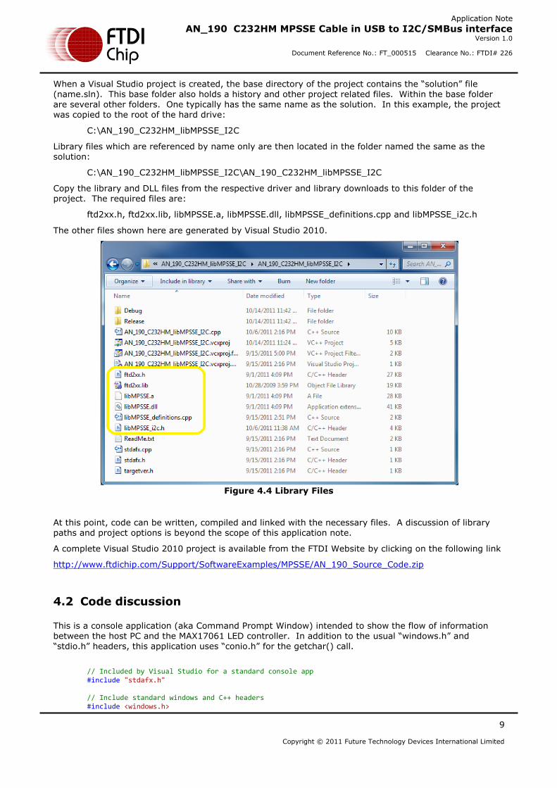
In addition to configuring the libraries, both configurations need to have optimization disabled. Within the project properties, select the Release configuration, and then navigate to the General properties. The last item is “Whole Program Optimization”. Select “No Whole Program Optimization”. Repeat for the Debug configuration.
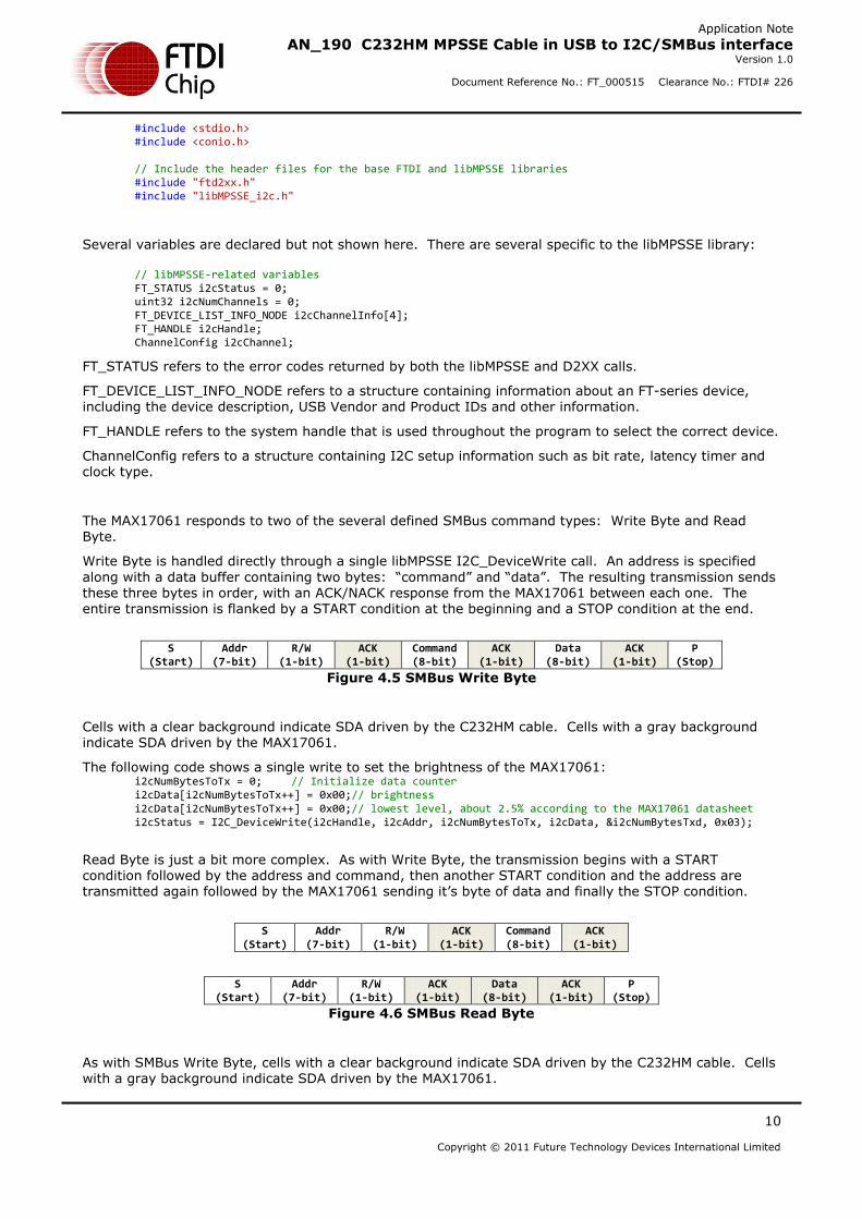
When a Visual Studio project is created, the base directory of the project contains the “solution” file (name.sln). This base folder also holds a history and other project related files. Within the base folder are several other folders. One typically has the same name as the solution. In this example, the project was copied to the root of the hard drive:
C:\AN_190_C232HM_libMPSSE_I2C
Library files which are referenced by name only are then located in the folder named the same as the solution:
This is a console application (aka Command Prompt Window) intended to show the flow of information between the host PC and the MAX17061 LED controller. In addition to the usual “windows.h” and “stdio.h” headers, this application uses “conio.h” for the getchar() call.
// Included by Visual Studio for a standard console app #include "stdafx.h" // Include standard windows and C++ headers #include <windows.h>
#include <stdio.h> #include <conio.h> // Include the header files for the base FTDI and libMPSSE libraries #include "ftd2xx.h" #include "libMPSSE_i2c.h"
Several variables are declared but not shown here. There are several specific to the libMPSSE library:
FT_STATUS refers to the error codes returned by both the libMPSSE and D2XX calls.
FT_DEVICE_LIST_INFO_NODE refers to a structure containing information about an FT-series device, including the device description, USB Vendor and Product IDs and other information.
FT_HANDLE refers to the system handle that is used throughout the program to select the correct device.
ChannelConfig refers to a structure containing I2C setup information such as bit rate, latency timer and clock type.
The MAX17061 responds to two of the several defined SMBus command types: Write Byte and Read Byte.
Write Byte is handled directly through a single libMPSSE I2C_DeviceWrite call. An address is specified
along with a data buffer containing two bytes: “command” and “data”. The resulting transmission sends
these three bytes in order, with an ACK/NACK response from the MAX17061 between each one. The entire transmission is flanked by a START condition at the beginning and a STOP condition at the end.
S
(Start) Addr
(7-bit) R/W
(1-bit) ACK
(1-bit) Command (8-bit)
ACK (1-bit)
Data (8-bit)
ACK (1-bit)
P (Stop)
Figure 4.5 SMBus Write Byte
Cells with a clear background indicate SDA driven by the C232HM cable. Cells with a gray background indicate SDA driven by the MAX17061.
The following code shows a single write to set the brightness of the MAX17061: i2cNumBytesToTx = 0; // Initialize data counter i2cData[i2cNumBytesToTx++] = 0x00;// brightness i2cData[i2cNumBytesToTx++] = 0x00;// lowest level, about 2.5% according to the MAX17061 datasheet i2cStatus = I2C_DeviceWrite(i2cHandle, i2cAddr, i2cNumBytesToTx, i2cData, &i2cNumBytesTxd, 0x03);
Read Byte is just a bit more complex. As with Write Byte, the transmission begins with a START condition followed by the address and command, then another START condition and the address are transmitted again followed by the MAX17061 sending it’s byte of data and finally the STOP condition.
S
(Start) Addr
(7-bit) R/W
(1-bit) ACK
(1-bit) Command (8-bit)
ACK (1-bit)
S
(Start) Addr
(7-bit) R/W
(1-bit) ACK
(1-bit) Data
(8-bit) ACK
(1-bit) P
(Stop)
Figure 4.6 SMBus Read Byte
As with SMBus Write Byte, cells with a clear background indicate SDA driven by the C232HM cable. Cells with a gray background indicate SDA driven by the MAX17061.
This sequence can be accomplished with an I2C_DeviceWrite call directly followed by an I2C_DeviceRead call as shown in this read of the status register: i2cNumBytesToTx = 0; // Initialize data counter i2cData[i2cNumBytesToTx++] = 0x02; // Status register i2cStatus = I2C_DeviceWrite(i2cHandle, i2cAddr, i2cNumBytesToTx, i2cData, &i2cNumBytesTxd, 0x01); i2cNumBytesToRx = 1; // Read one byte i2cStatus += I2C_DeviceRead(i2cHandle, i2cAddr, i2cNumBytesToRx, &i2cData[0], &i2cNumBytesRxd, 0x03);
Notice the last argument of the write is 0x01. This causes the sequence to begin with the START but don’t include the STOP when done. The bus remains active until the the read is complete with the last argument of 0x03. The read sends another START and completes with a STOP. Although these calls are initially geared toward a more general I2C use, it’s shown here that they can be combined to satisfy SMBus command structures as well.
The application reads and writes each of the available registers of the MAX17061, ultimately causing the LEDs to turn on, ramp from low to full brightness and back down to low, and then finally close the port
and exit.
Although this application note shows a Visual Studio application, similar code could be complied on a Linux system with the Linux version of the libMPSSE.a library and D2XX device drivers.
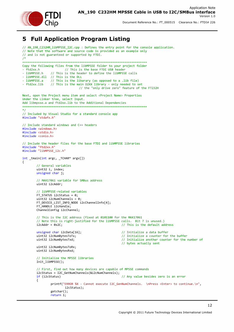
// AN_190_C232HM_libMPSSE_I2C.cpp : Defines the entry point for the console application. // Note that the software and source code is provided as an example only // and is not guaranteed or supported by FTDI. /* ======================================================================== Copy the following files from the libMPSSE folder to your project folder - ftd2xx.h // This is the base FTDI USB header - libMPSSE.h // This is the header to define the libMPSSE calls - libMPSSE.dll // This is the DLL - libMPSSE.a // This is the libarary (as opposed to a .lib file) - ftd2xx.lib // This is the main D2XX library - only needed to set // the "only drive zero" feature of the FT232H Next, open the Project menu item and select <Project Name> Properties Under the Linker tree, select Input. Add libmpsse.a and ftd2xx.lib to the Additional Dependencies ======================================================================== */ // Included by Visual Studio for a standard console app #include "stdafx.h" // Include standard windows and C++ headers #include <windows.h> #include <stdio.h> #include <conio.h> // Include the header files for the base FTDI and libMPSSE libraries #include "ftd2xx.h" #include "libMPSSE_i2c.h" int _tmain(int argc, _TCHAR* argv[]) { // General variables uint32 i, index; unsigned char j; // MAX17061 variable for SMBus address uint32 i2cAddr; // libMPSSE-related variables FT_STATUS i2cStatus = 0; uint32 i2cNumChannels = 0; FT_DEVICE_LIST_INFO_NODE i2cChannelInfo[4]; FT_HANDLE i2cHandle; ChannelConfig i2cChannel; // This is the I2C address (fixed at 0101100 for the MAX17061 // Note this is right-justified for the libMPSSE calls. Bit 7 is unused.) i2cAddr = 0x2C; // This is the default address unsigned char i2cData[16]; // Initialize a data buffer uint32 i2cNumBytesToTx; // Initialize a counter for the buffer uint32 i2cNumBytesTxd; // Initialize another counter for the number of
// bytes actually sent uint32 i2cNumBytesToRx; uint32 i2cNumBytesRxd; // Initialize the MPSSE libraries Init_libMPSSE(); // First, find out how many devices are capable of MPSSE commands i2cStatus = I2C_GetNumChannels(&i2cNumChannels); if (i2cStatus) // Any value besides zero is an error { printf("ERROR %X - Cannot execute I2C_GenNumChannels. \nPress <Enter> to continue.\n",
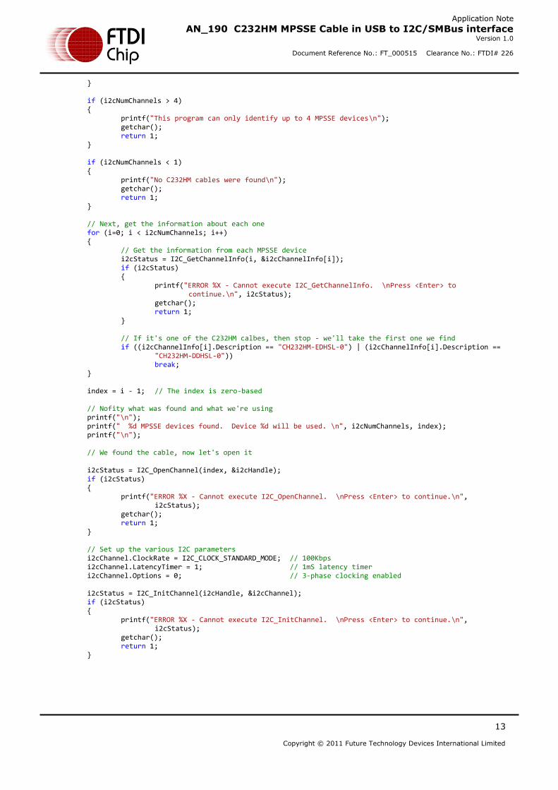
} if (i2cNumChannels > 4) { printf("This program can only identify up to 4 MPSSE devices\n"); getchar(); return 1; } if (i2cNumChannels < 1) { printf("No C232HM cables were found\n"); getchar(); return 1; } // Next, get the information about each one for (i=0; i < i2cNumChannels; i++) { // Get the information from each MPSSE device i2cStatus = I2C_GetChannelInfo(i, &i2cChannelInfo[i]); if (i2cStatus) { printf("ERROR %X - Cannot execute I2C_GetChannelInfo. \nPress <Enter> to
continue.\n", i2cStatus); getchar(); return 1; } // If it's one of the C232HM calbes, then stop - we'll take the first one we find if ((i2cChannelInfo[i].Description == "CH232HM-EDHSL-0") | (i2cChannelInfo[i].Description ==
"CH232HM-DDHSL-0")) break; } index = i - 1; // The index is zero-based // Nofity what was found and what we're using printf("\n"); printf(" %d MPSSE devices found. Device %d will be used. \n", i2cNumChannels, index); printf("\n"); // We found the cable, now let's open it i2cStatus = I2C_OpenChannel(index, &i2cHandle); if (i2cStatus) { printf("ERROR %X - Cannot execute I2C_OpenChannel. \nPress <Enter> to continue.\n",
i2cStatus); getchar(); return 1; } // Set up the various I2C parameters i2cChannel.ClockRate = I2C_CLOCK_STANDARD_MODE; // 100Kbps i2cChannel.LatencyTimer = 1; // 1mS latency timer i2cChannel.Options = 0; // 3-phase clocking enabled i2cStatus = I2C_InitChannel(i2cHandle, &i2cChannel); if (i2cStatus) { printf("ERROR %X - Cannot execute I2C_InitChannel. \nPress <Enter> to continue.\n",
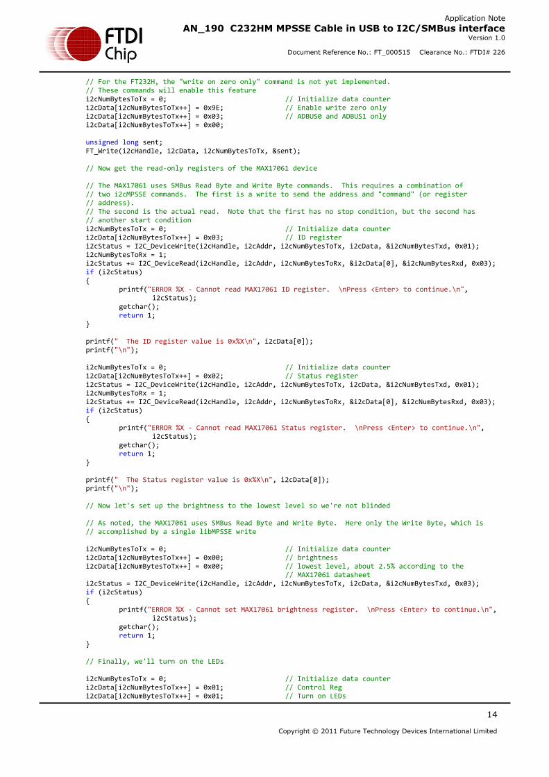
// For the FT232H, the "write on zero only" command is not yet implemented. // These commands will enable this feature i2cNumBytesToTx = 0; // Initialize data counter i2cData[i2cNumBytesToTx++] = 0x9E; // Enable write zero only i2cData[i2cNumBytesToTx++] = 0x03; // ADBUS0 and ADBUS1 only i2cData[i2cNumBytesToTx++] = 0x00; unsigned long sent; FT_Write(i2cHandle, i2cData, i2cNumBytesToTx, &sent); // Now get the read-only registers of the MAX17061 device // The MAX17061 uses SMBus Read Byte and Write Byte commands. This requires a combination of // two i2cMPSSE commands. The first is a write to send the address and "command" (or register
// address). // The second is the actual read. Note that the first has no stop condition, but the second has
// another start condition i2cNumBytesToTx = 0; // Initialize data counter i2cData[i2cNumBytesToTx++] = 0x03; // ID register i2cStatus = I2C_DeviceWrite(i2cHandle, i2cAddr, i2cNumBytesToTx, i2cData, &i2cNumBytesTxd, 0x01); i2cNumBytesToRx = 1; i2cStatus += I2C_DeviceRead(i2cHandle, i2cAddr, i2cNumBytesToRx, &i2cData[0], &i2cNumBytesRxd, 0x03); if (i2cStatus) { printf("ERROR %X - Cannot read MAX17061 ID register. \nPress <Enter> to continue.\n",
i2cStatus); getchar(); return 1; } printf(" The ID register value is 0x%X\n", i2cData[0]); printf("\n"); i2cNumBytesToTx = 0; // Initialize data counter i2cData[i2cNumBytesToTx++] = 0x02; // Status register i2cStatus = I2C_DeviceWrite(i2cHandle, i2cAddr, i2cNumBytesToTx, i2cData, &i2cNumBytesTxd, 0x01); i2cNumBytesToRx = 1; i2cStatus += I2C_DeviceRead(i2cHandle, i2cAddr, i2cNumBytesToRx, &i2cData[0], &i2cNumBytesRxd, 0x03); if (i2cStatus) { printf("ERROR %X - Cannot read MAX17061 Status register. \nPress <Enter> to continue.\n",
i2cStatus); getchar(); return 1; } printf(" The Status register value is 0x%X\n", i2cData[0]); printf("\n"); // Now let's set up the brightness to the lowest level so we're not blinded // As noted, the MAX17061 uses SMBus Read Byte and Write Byte. Here only the Write Byte, which is // accomplished by a single libMPSSE write i2cNumBytesToTx = 0; // Initialize data counter i2cData[i2cNumBytesToTx++] = 0x00; // brightness i2cData[i2cNumBytesToTx++] = 0x00; // lowest level, about 2.5% according to the
// MAX17061 datasheet i2cStatus = I2C_DeviceWrite(i2cHandle, i2cAddr, i2cNumBytesToTx, i2cData, &i2cNumBytesTxd, 0x03); if (i2cStatus) { printf("ERROR %X - Cannot set MAX17061 brightness register. \nPress <Enter> to continue.\n",
i2cStatus); getchar(); return 1; } // Finally, we'll turn on the LEDs i2cNumBytesToTx = 0; // Initialize data counter i2cData[i2cNumBytesToTx++] = 0x01; // Control Reg i2cData[i2cNumBytesToTx++] = 0x01; // Turn on LEDs
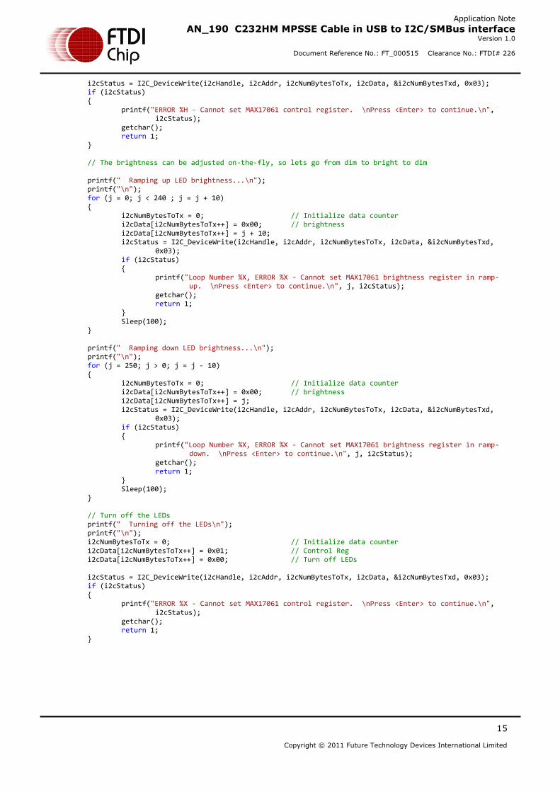
i2cStatus = I2C_DeviceWrite(i2cHandle, i2cAddr, i2cNumBytesToTx, i2cData, &i2cNumBytesTxd, 0x03); if (i2cStatus) { printf("ERROR %H - Cannot set MAX17061 control register. \nPress <Enter> to continue.\n",
i2cStatus); getchar(); return 1; } // The brightness can be adjusted on-the-fly, so lets go from dim to bright to dim printf(" Ramping up LED brightness...\n"); printf("\n"); for (j = 0; j < 240 ; j = j + 10) { i2cNumBytesToTx = 0; // Initialize data counter i2cData[i2cNumBytesToTx++] = 0x00; // brightness i2cData[i2cNumBytesToTx++] = j + 10; i2cStatus = I2C_DeviceWrite(i2cHandle, i2cAddr, i2cNumBytesToTx, i2cData, &i2cNumBytesTxd,
0x03); if (i2cStatus) { printf("Loop Number %X, ERROR %X - Cannot set MAX17061 brightness register in ramp-
// Turn off the LEDs printf(" Turning off the LEDs\n"); printf("\n"); i2cNumBytesToTx = 0; // Initialize data counter i2cData[i2cNumBytesToTx++] = 0x01; // Control Reg i2cData[i2cNumBytesToTx++] = 0x00; // Turn off LEDs i2cStatus = I2C_DeviceWrite(i2cHandle, i2cAddr, i2cNumBytesToTx, i2cData, &i2cNumBytesTxd, 0x03); if (i2cStatus) { printf("ERROR %X - Cannot set MAX17061 control register. \nPress <Enter> to continue.\n",
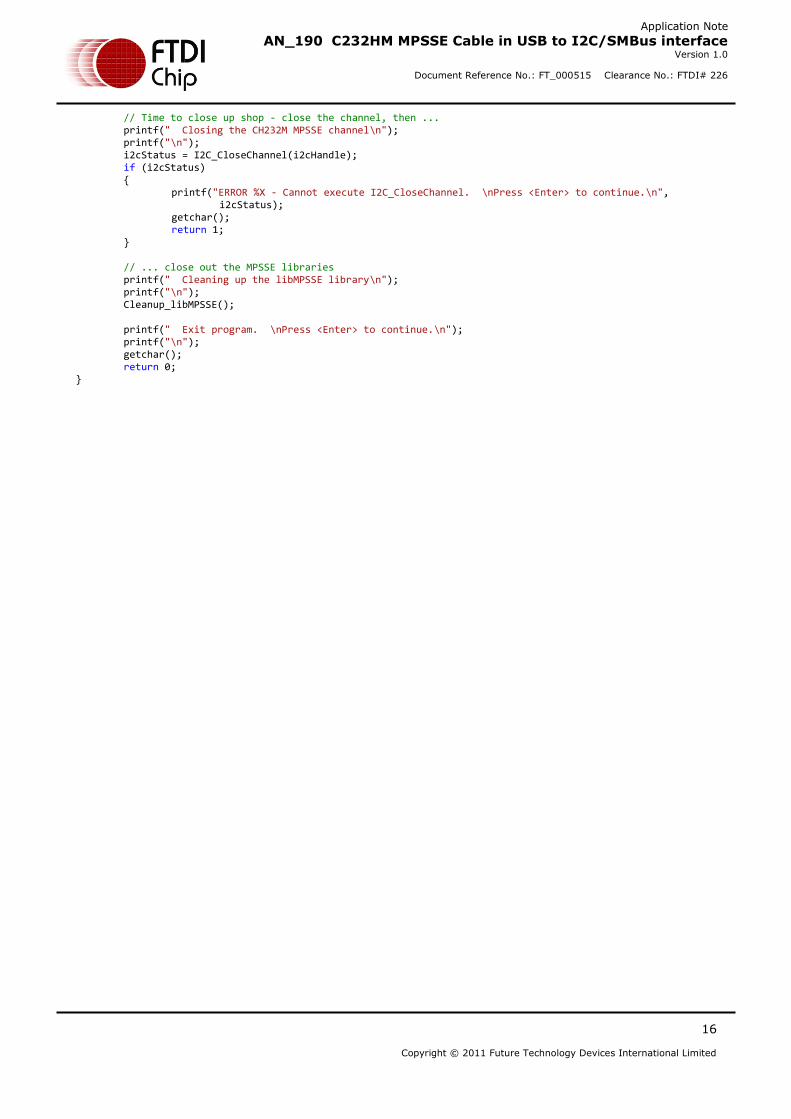
// Time to close up shop - close the channel, then ... printf(" Closing the CH232M MPSSE channel\n"); printf("\n"); i2cStatus = I2C_CloseChannel(i2cHandle); if (i2cStatus) { printf("ERROR %X - Cannot execute I2C_CloseChannel. \nPress <Enter> to continue.\n",
i2cStatus); getchar(); return 1; } // ... close out the MPSSE libraries printf(" Cleaning up the libMPSSE library\n"); printf("\n"); Cleanup_libMPSSE(); printf(" Exit program. \nPress <Enter> to continue.\n"); printf("\n"); getchar(); return 0; }
The FTDI ICs which incorporate the Multi-Protocol Synchronous Serial Engine provide a versatile interface to SPI, JTAG and I2C devices. This application note demonstrated the I2C functionality and specifically the SMBus customization of the I2C protocol through the use of the libMPSSE-I2C Application Programming Interface (API).
For SPI use, readers are encouraged to refer to Application Note AN_188, Using the C232HM MPSSE Cable in USB to SPI Interface for using the same cable in a SPI application with the libMPSSE-SPI API.
Basic JTAG operation is shown in AN_129, FTDI Hi-Speed USB to JTAG Example.
Please visit the Sales Network page of the FTDI Web site for the contact details of our distributor(s) and sales
representative(s) in your country.
System and equipment manufacturers and designers are responsible to ensure that their systems, and any Future Technology Devices
International Ltd (FTDI) devices incorporated in their systems, meet all applicable safety, regulatory and system-level performance
requirements. All application-related information in this document (including application descriptions, suggested FTDI devices and other
materials) is provided for reference only. While FTDI has taken care to assure it is accurate, this information is subject to customer confirmation, and FTDI disclaims all liability for system designs and for any applications assistance provided by FTDI. Use of FTDI
devices in life support and/or safety applications is entirely at the user’s risk, and the user agrees to defend, indemnify and hold
harmless FTDI from any and all damages, claims, suits or expense resulting from such use. This document is subject to change without
notice. No freedom to use patents or other intellectual property rights is implied by the publication of this document. Neither the whole
nor any part of the information contained in, or the product described in this document, may be adapted or reproduced in any material
or electronic form without the prior written consent of the copyright holder. Future Technology Devices International Ltd, Unit 1, 2
Seaward Place, Centurion Business Park, Glasgow G41 1HH, United Kingdom. Scotland Registered Company Number: SC136640