4
Oil Level Gauges 70.50-4us C5.3511 · C5.3516 C5.3529 · With thermometer · Indication range up to 7.64 inch · Temperature indication up to 180 °F

Oi l Leve l Gauges
70.50-4us
C5.3511 · C5.3516C5.3529· With thermometer
· Indication range up to 7.64 inch
· Temperature indication up to 180 °F

Descr i p t ion
Se l ec t ion Char t
Special features• The robust metal housing is designed to withstand even the most severe operating conditions.• The integrated scale shows the oil temperature in °C and °F.
MountingThe hollow screws and the locking nuts supplied with the gauge, enable installation on the reservoir wall. The locking nuts serve the purpose of retightening the bolts from the outside (assembly torque: 8 Nm). Threaded holes are required instead of smooth bore holes if the wall of the reservoir is more than 0.33 inch thick.
ApplicationIndicates the oil level and the oil temperature in hydraulic oil or lubricant reservoirs.
Design and functionARGO-HYTOS oil level gauges consist of a robust metal housing equipped with a sight level tube and built-in thermometer. The fluid enters the thermometer chamber through the mounting bolts, which are hollow. O-rings provide a seal against the housing and the reservoir wall.
Part No.
Remarks
Total height B
Oil level
indicating range E
Weight
Tempera
ture indica
ting range
Tempera
ture indica
ting range
Mounting bolts
inch lbs°C °Finch
C5.3511-50 1.30 4.25 +20 ... +80 80 ... 180 M10 0.40 -
C5.3516-50 2.91 6.26 -10 ... +80 20 ... 180 M12 0.53 -
C5.3529-50 7.64 11.22 -10 ... +80 20 ... 180 M12 0.71 -
1 2 3 4 5 6 7 8
Remarks:The gauges listed in the chart are standard gauges. If modifications are required, we kindly ask for your request.
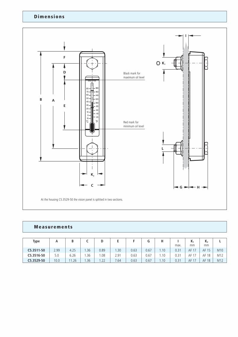
D i m en s ions
Measu rements
Type A B C D E F G H I K1 K2 L max. mm mm C5.3511-50 2.99 4.25 1.36 0.89 1.30 0.63 0.67 1.10 0.31 AF 17 AF 15 M10 C5.3516-50 5.0 6.26 1.36 1.08 2.91 0.63 0.67 1.10 0.31 AF 17 AF 18 M12 C5.3529-50 10.0 11.26 1.36 1.22 7.64 0.63 0.67 1.10 0.31 AF 17 AF 18 M12
F
D
B AE
K2
C
I
L
G H
K1
ARGO-HYTOS
Black mark formaximum oil level
Red mark forminimum oil level
At the housing C5.3529-50 the vision panel is splitted in two sections.

Our engineers will be glad to advise you in questions concerning filter application, selection as well as the cleanliness class of the filtered medium attainable under practical operating conditions.
Illustrations may sometimes differ from the original. ARGO-HYTOS is not responsible for any unintentional mistake in this specification sheet.
Subject to change70.50-4us · 0714
Ch arac ter i s t i c s
Q u a l i ty Assurance
Operating pressureMax. 29 psi (abs.)
Connection Threaded ports according to DIN 13. Sizes see Selection Chart, column 6 and section Dimensions.
Hydraulic fluids Mineral oil and biodegradable fluids (HEES and HETG, see info-sheet 00.20).
Temperature range - 4 °F ... + 176 °F
Ambient temperature range - 13°F ... + 176 °C
MaterialsHousing: Steel, powder coated, blackSight level tube: PolyamideScale: AluminumThermometer: GlassBolts: Steel, zinc platedSeals: NBR (FKM on request)
Mounting position In the min./max. oil level range on the side wall of the hydraulic oil reservoir.
We produce fluid power solutionsARGO-HYTOS Inc. · P.O. Box 28 · Bowling Green, OH 43402 · USAPhone: +1-419-353-6070 · Fax: +1-419-354-3496 · [email protected] · www.argo-hytos.com
Quality management according to DIN EN ISO 9001
Various quality controls during the production process guarantee the leakfree function and solidity of our filters.


