All Rights Reserved. No part of this publication may be reproduced without prior written consent from
EDSA Micro Corporation.
Advanced Power Cable Ampacity Program
Version 5.10.00 iii Advanced Power Cable Ampacity Program Dec 2005
USERS GUIDE
TABLE OF CONTENTS Foreword:.......................................................................................................................................................................................... 5What's New in this Release of the Cable Ampacity Program…………………………………………………………. ……5 Overview........................................................................................................................................................................................... 6 Upcoming Features in the Next Program Release ........................................................................................................................... 6 Background....................................................................................................................................................................................... 7
General Data ................................................................................................................................................................................ 8 Cable in Air ................................................................................................................................................................................... 8 Solar Radiation ............................................................................................................................................................................. 9 Heat Source/Sink........................................................................................................................................................................ 10 Installation .................................................................................................................................................................................. 10 Possible Cable Installation Conditions ....................................................................................................................................... 10 Backfill ........................................................................................................................................................................................ 11 Conductor Material ..................................................................................................................................................................... 11 Conductor Construction.............................................................................................................................................................. 11 Dried And Impregnated .............................................................................................................................................................. 12 Conductor Losses....................................................................................................................................................................... 12 Cable Insulation.......................................................................................................................................................................... 12 Skid/Concentric Neutral Material ................................................................................................................................................ 14 Bonding Arrangement................................................................................................................................................................. 14 Loss Factor Constant ................................................................................................................................................................. 14 Jacket/Pipe Coating Material...................................................................................................................................................... 14 Armor/Reinforcement Material.................................................................................................................................................... 14 Armor Bedding, Serving Material................................................................................................................................................ 14 Armor Permeability ..................................................................................................................................................................... 15 Insulation Shielding .................................................................................................................................................................... 15 Sheath/Reinforcing Material ....................................................................................................................................................... 15 Cable Transposition.................................................................................................................................................................... 16 Pipe Material and Configuration ................................................................................................................................................. 16 Material and Construction of the Ductbank or Duct.................................................................................................................... 16 Cable Dimensions ...................................................................................................................................................................... 17
Running Cable Ampacity Program.................................................................................................................................................. 21 Loading Sample Cable/Project Library ........................................................................................................................................... 21 Provided Sample Projects............................................................................................................................................................... 22 Step by Step Instructions for Adding a New Cable Type................................................................................................................ 23 Using the Drop-Down Menu............................................................................................................................................................ 24 Adding/Creating a New Cable Type Using the Wizard ................................................................................................................... 26 How to Add/Create a Project/Study ................................................................................................................................................ 40 How to Run a Simulation ................................................................................................................................................................ 48 Program Validation and Verification................................................................................................................................................ 51 References – Bibliography.............................................................................................................................................................. 52 APPENDIX I: IEC & Neher-Mcgrath Cable Ampacity Calculations Methodology ........................................................................... 54 APPENDIX II: Some Useful Diagrams and Figures........................................................................................................................ 57 APPENDIX III: Tables of Material Properties.................................................................................................................................. 69
Advanced Power Cable Ampacity Program
Version 5.10.00 iv Advanced Power Cable Ampacity Program Dec 2005
LIST OF TABLES
Table 1: Comparing Results of Neher McGrath and EDSA’s Cable Ampacity Program 52 Table 2: Specific Inductive Capacitance of Insulation 69 Table 3: Thermal Resistivity of Various Materials 69 Table 4: Pipe Constants 69 Table 5: Conductor Material 70 Table 6: Dielectric Loss 70 Table 7: Resistivities of Materials 70 Table 8: Absorption Coefficients of Solar Radiation 71 Table 9: Constants For Ducts Or Pipes 71
LIST OF FIGURES Figure 1: Main Menu of Cable Ampacity program .......................................................................................................................... 21 Figure 2: Opening a cable/project library ........................................................................................................................................ 21 Figure 3: Main Cable Menu after a cable/project library is loaded.................................................................................................. 22 Figure 4: Cable Type Dialogs ......................................................................................................................................................... 23 Figure 5: Cable Conductor Dialog................................................................................................................................................... 24 Figure 6: Selecting an Item from the Dropdown Menus.................................................................................................................. 24 Figure 7: Cable General Data Dialog.............................................................................................................................................. 26 Figure 8: Conductor Data Dialog .................................................................................................................................................... 27 Figure 9: Conductor Dimension Data Dialog .................................................................................................................................. 28 Figure 10: Cable Insulation Data Dialog ......................................................................................................................................... 29 Figure 11: Cable Insulation Dimension Data Dialog ....................................................................................................................... 30 Figure 12: Cable Sheath Data Dialog ............................................................................................................................................. 31 Figure 13: Reinforcing Tape Data Dialog........................................................................................................................................ 32 Figure 14: Reinforcing Tape Dimension Data Dialog...................................................................................................................... 33 Figure 15: Concentric Neutral/Skid Wire Data Dialog..................................................................................................................... 35 Figure 16: Jacket/Pipe Coating Data Dialog ................................................................................................................................... 36 Figure 17: Armor/Serving/Bedding Data Dialog.............................................................................................................................. 37 Figure 18: Overall Cable Dimension Data Dialog ........................................................................................................................... 38 Figure 19: Project/Study General Data Dialog................................................................................................................................ 42 Figure 20: Adding a Cable to a Study/Project................................................................................................................................. 44 Figure 21: Selecting a Cable from the Cable Type Library ............................................................................................................. 45 Figure 22: Report Browser Window Showing the Result of Amapcity Calculation ......................................................................... 49 Figure 23: 138 kV, 2000 MCM high pressure oil-filled, 3-conductor, pipe type cable..................................................................... 51 Figure 24: Basic Thermal Circuit .................................................................................................................................................... 54 Figure 25: Definition of Thermal-Ohm Units ................................................................................................................................... 55 Figure 26: Mathematical Model of a Cable Thermal Circuit............................................................................................................ 55 Figure 27: Cable Topology / General Parameters Self Contained Cables ..................................................................................... 67 Figure 28: Typical Pipe Cable Cross-Section ................................................................................................................................. 67 Figure 29: Configuration of Cable in the Duct/Conduit ................................................................................................................... 68 Figure 30: Ductbank Gb Factor ....................................................................................................................................................... 68
Advanced Power Cable Ampacity Program
Version 5.10.00 5 Advanced Power Cable Ampacity Program Dec 2005
Foreword: This manual assumes that the user is a Professional Engineer familiar with the concepts of cable ampacity calculation. Determination of the validity of the results is the user's responsibility. The IEC (International Electrotechnical Commission) and Neher-McGrath cable ampacity program is undergoing continuous development to make it as comprehensive and as easy to use as possible. Additional analysis capabilities will be made available as they are developed. Any comments, suggestions or errors encountered in either the results or the documentation should be immediately brought to EDSA’s attention. It is recommended that users of the program experiment with the sample job files that are included before creating their own job files. It is also recommended that users consult the relevant papers on which the program is based: IEC Standards 287, Neher-McGrath IEEE paper 57-660 and Underground Transmission Systems Reference Book, Electric Power Research Institute, 1992 Edition. This program is intended to be a very easy to use tool. However, it is expected that the user of the program have good knowledge of the cable construction and ampacity calculations. What’s New in This Release of the Cable Ampacity Program
1) The cable ampacity program was enhanced to facilitate the simulation of touching cables. When three cables are in touching arrangement either directly buried or inside a duct/ductbank, the user need not enter the coordinates of each cable. Instead, it is sufficient to enter just one cable whose coordinates is the same as the center of the three cables. Also, the user should select “Cables Touching” option in the program. This option, when selected, instructs the cable ampacity program to consider three cables even though the user has just given the coordinates of one cable.
2) Computation of the cable sheath losses when a cable has no skid/concentric neutral wires, no
armor, or no reinforcement tape was modified to correctly reflect the modeling of this type cables.
3) As part of the program V&V, the sample case for the pipe type cable from the Neher-McGrath paper was simulated. The computed ampacity for this sample case, using the EDSA’s cable program, is 904 amperes versus 905 amperes which is reported in the Neher-McGrath paper. The discrepancy between the two result is less than 0.1 %
Advanced Power Cable Ampacity Program
Version 5.10.00 6 Advanced Power Cable Ampacity Program Dec 2005
Overview Cable ampacity assessment and temperature rise calculations is an important but time consuming task for cable manufacturers, designers and operators. This is due to the fact the computations often includes numerous mathematical calculations and extensive table look up and data processing. EDSA has developed an efficient computer program in order to facilitate such calculations. The EDSA cable ampacity program utilizes the techniques and formulae suggested in the IEC (International Electrotechnical Commission) standard publication No. 287-1982 to compute the temperature rise and ampacity of power cables. This program also offers an alternative computational method to handle non-unity load factor based on the Neher-McGrath technique. Several enhancements to both Neher McGrath and IEC 287 standard have been implemented. These include:
he neighborhood of energized cables Simulation of soil drying out in t
Nonisothermal earth surface
Cables without metallic sheath but with copper concentric neutral that can be single or both ends
ith or without concentric neutral or metallic sheath
Single phase circuits consisting of one single core cable with concentric neutral wires or sheath
Ductbanks and backfills of any size
Up The
quivalent thermal circuit of the cable. Each cable in a study can be subjected to different time dependent load curve
The steady-state computation will support mix of ampacity and temperature calculation where a group cables will have assigned ampacities while the program will compute ampacities for another group of cables without exceeding their maximum temperature
will have full graphical display of result including temperature distribution along cable cross section
bonded and grounded
Steel armoured submarine cables w
Cables on riser poles
serving as the return conductor.
PPP (Paper-polypropylene-paper) laminated cables.
coming Features in the Next Program Release
program update will include the following enhancements:
Transient analysis: In the next release, the EDSA users can assess the short term transient response of power cables given load variation pattern. The computation methodology is based on the principles recommended in the IEC Publication 853-2. The program adopts lump parameters and image techniques to calculate the transient temperature rise of cables among a set of equally or unequally loaded, similar or dissimilar cables. The temperature profiles, ampacities, and time information are computed using the e
The program
Advanced Power Cable Ampacity Program
Version 5.10.00 7 Advanced Power Cable Ampacity Program Dec 2005
Background
he EDSA’s advanced power cable ampacity program supports all AC as well as DC voltages. Cables Tcan be directly buried, be in ducts, be in steel pipes, as well as in air. The permissible current rating of an a.c. cable can be derived from the expression for the temperature rise above ambient temperature:
[ ] [ ] [ ] )T(TW)1(RITW)1(RITW0.5RI 43d212
2d2
1d2 +++++++++=Δ nn λλλθ
Where:
rrent flowing in one conductor (Amps). I is the cu θΔ is the conductor temperature rise above the ambient temperature (K). Note: The ambient
perature is the temperature of the surrounding medium under normal conditions in a situation in which but not the
crease of temperature in the immediate neighborhood of the cables due to heat arising there from.
rature m/m).
is the dielectric loss per unit length for the insulation surrounding the conductor (W/m).
is the thermal resistance per unit length between one conductor and the sheath (K.m/W).
2 he thermal resistance per unit length of the bedding between the sheath and armor (k.m/W).
um (K.m/W).
is the number of load carrying conductors in the cable (conductors of equal size and carrying the same ).
1
temcables are installed, or are to be installed, including the effect of any local source of heat,in R is the alternating current resistance per unit length of the conductor at maximum operating tempe(oh
dW
1T
T
is t
3T is the thermal resistance per unit length of the external serving of the cable (K.m/W).
4T is the thermal resistance per unit length between cable surface and the surrounding medi nload
λ is the ratio of losses in the rs in that cable. metal sheath to total losses in all conducto
2λ is the ratio of losses in the armoring to total losses in all conductors in that cable. The permissible current rating is obtained from the above formula as follows:
)TT()1(RT)1]()TTT(n0.5T[WI
432121
4321d
mQm
+++++Δ−+++−Δ
=λλλ
θ
e between critical isotherm (50 ºC) and the ambient (critical isotherm is one at hich drying out occurs), m is the ratio of the thermal resistivities of the dry and moist soil zones. The
an imaginary additional layer of soil d meters thick at the re:
nR1 1(nRT) +
ΔQ is temperature differenc
wnonisothermal surface is modeled by introducingearth surface, whe
0
1ρa
d =
Advanced Power Cable Ampacity Program
Version 5.10.00 8 Advanced Power Cable Ampacity Program Dec 2005
a is the convection coefficient and 0ρ is the thermal resistivity of the moist soil. The program computes the convection coefficient.
Genatte
mbient.
e higher the value of the resistivity, the lower the ampacity.
of dry crushed limestone usually cannot be higher than 1.5 C-W/m. Another factor affecting the value of the soil thermal resistivity is its compaction. The higher the soil compaction, the lower is its thermal resistivity. If the soil thermal
nknown, the more conservative value of 1.3 can be used as a starting point.
The heat source/sink data if any.
perature gr e
y soil (and backfill if present) thermal ity is larger than the moist values.
Cable in Air
Installation Z E CG ion
a) -continuou rackets, ladder supports, or cleats:
Single cable 0.21 3.94 0.60
General Data
eral site configuration data as outlined below should be specified. The following items require special ntion:
Ambient temperature and soil resistivity values should correspond to the installation situation and not to the test condition of the manufacturer. Ambient temperature is the soil ambient at the depth of the cable if the cable is buried. If the cable is installed in air, ambient temperature means air a
Soil thermal resistivity is normally in the range of 0.8 to 1.3 C-W/m. Values as low as 0.4 and as high as 4 C-W/m have been recorded in field. Thermal resistivity of the soil is one of the most important parameters affecting cable ampacity. ThThermal resistivity increases with the decrease in moisture content in the soil. Thermal resistivity of dry sand can be as high as 5 C-W/m, whereas, thermal resistivity
resistivity is u
For a nonisothermal surface, the user should enter the air ambient temperature. This temshould be greater than the soil ambient. If the cables are locate t a depth eater than 1.5 m, thnonisothermal condition does not apply.
d a
For simulation of soil drying out, the user should enter drresistivity. The dry thermal resistiv
For cables in air, the following possible configurations are supported.
Configurat
Cables in free air, installed on non s b
Two cables, touching, horizontal 0.29 2.35 0.50
Advanced Power Cable Ampacity Program
Version 5.10.00 9 Advanced Power Cable Ampacity Program Dec 2005
Three cables in trefoi 0.96 1.25 0.20 l
Three cables, touching, horizontal 0.62 1.95 0.25
Two cables, touching, vertical 1.42 0.86 0.25
Two cables, spaced eD' , vertical 0.75 2.80 0.30
Three cables, touching, vertical 1.61 0.42 0.20
ced eD' , vertical 1.31 2.00 0.20 Three cables, spa
b) Cables directly clipped to a vertical wall:
Single cable 1.69 0.63 0.25
Three cables in trefoil 0.94 0.79 0.20
So
n is required in addition to the cable arrangement as
a) Shaded or un-shaded cable. For shaded cable the next two items do not apply.
llowing default values are provided, however, the
0.8
lar Radiation
hen cables are in air, the following informatioWshown above:
b) Intensity of solar radiation (W/m2). The radiation should represent the long-term average value. c) The cable surface absorption coefficient. The fo
user can change the value if required:
Compounded jute/fibrous materials = 0.8
Polychloroprene =
Advanced Power Cable Ampacity Program
Version 5.10.00 10 Advanced Power Cable Ampacity Program Dec 2005
Polyvinylchloride = 0.6
Polyethylene = 0.4
He The
ote that the unit of heat source for the heat flux option is defined as W/m2. Temperature is given in egrees C for the case of constant temperature.
rigin of the coordinate system such that the Y Y=0.0 at the ground level). The X values may
n of the X-axis in normally decided by the ease of entering cable coordinates. For cables installed in air, the Y location has no significance and can be set to 0.
it. The user should not define more than ee cables of the same circuit should be
es) cable. The program finds the ampacity of the reference cable at its maximum operating temperature and the ampacities of the remaining cables will be the highest possible without exceeding their thermal ratings.
Cables are in air or cables are in duct and duct is in air.
ed.
al backfill.
Lead or armour = 0.6
at Source/Sink
heat source/sink in proximity of cables can be simulated with the following four possibilities:
External source specified as constant temperature source inside backfill.
External source specified as constant heat flux source inside backfill.
External source specified as constant temperature source not in backfill.
External source specified as constant heat flux source not in backfill.
Nd
Installation
Cable geometrical coordinates should be defined with ovalues for buried cables are always a positive number (be either positive or negative. The choice of the origi
Circuit number identifies the three phases of the cable circuone cable specified for the same circuit number; all of the throf the same cable type.
Selection of a reference (for dissimilar or unequally loaded cabl
Possible Cable Installation Conditions The following is a list of possible cable installations for self contained cables:
Cables are directly buri
Cables are in therm
Advanced Power Cable Ampacity Program
Version 5.10.00 11 Advanced Power Cable Ampacity Program Dec 2005
Cables are in duct or in duct bank underground. For pipe type cable:
Cables are in pipe and pipe is directly buried.
al backfill.
Not a bles.
Ba i Bac The program can only handle two different material ackfills/ductbanks can be simulated. Backfill or
uc n sistivity. The thermal resistivity of the backfill is te thermal resistivity is usually in the range of 0.5 to 0.8
Con ctor material is your defined, then, e as well as thermal coefficient of
n can be any of the following available choices:
round, stranded
Cables are in pipe and pipe is in therm
Cables are in pipe and pipe is in air.
e th t Pipe type cables are treated as three-conductor ca
ckf ll
kfill data pertain to thermal backfills or to ductbanks. s surrounding the cable. Only rectangular b
tba k is defined by its dimensions and thermal redusually lower than that of the native soil. Concre
. ºC-W/m
Conductor Material
ductor material can be copper, aluminum, or user defined. If conduuser should provide the conductor resistivity at 20 ºC (in Ohm-m)th
resistance in 1/(ºC).
Conductor Construction The conductor constructio
round, compact or compressed
type m, round segmental type m, 4 segment hollow core
hollow core
type m, six segment hollow core
sector shaped
oval
solid
Advanced Power Cable Ampacity Program
Version 5.10.00 12 Advanced Power Cable Ampacity Program Dec 2005
Note: sector sha cables.
nated
Dep ient for calculati and pro it
Co u The rature is comp ted fro
Racm = Rdcm ( 1 + Ys + Yp ) Wh Rdc is AC re stance at max ature; Ys is skin e uments of B or co er and aluminu as follow:
ped cables are 3-phase
Dried And Impreg
cable dried and impregnated
cable not dried and impregnated or not applicable
ending on the selection the program will establish the proper coeffic on of skin xim y factors.
nd ctor Losses a.c. resistance of the conductor at its maximum tempe u m:
ere:
m is DC resistance at maximum temperature; Ra si imum tempercm eff ct factor; Yp is proximity effect factor. Yp and Ys are functions of Kp and Ks as well as argessel function. Ks and Kp are assumed to be the same f pp m defined
Round, stranded dried and impregnated Ks=1.0 Kp=0.8 Round, stranded not dried and impregnated K =1.0 K =1.0 s pRound, compact dried and impregnated Ks=1.0 Kp=0.8 Round, compact not dried and impregnated Ks=1.0 Kp=1.0 Round, segmental (values apply to conductors having four segments ) K =0.435 K =0.3 7 s pHollow, helical stranded dried and impregnated Ks= K*
p=0.8 Sector shaped dried and impregnated K s=1 Kp=0.8 Sector shaped not dried and impregna Kted s=1 Kp=1.0
*decided based on
2
i'' 2dddd ⎟
⎞⎛ +−
i⎟⎠
hich is fu ction of inside and tside di
cted from the followin availa le choi s a different , then, thermal resistivi of the provided:
solid type or mass impregnated, non draining cable, RHI=6.
5.0
RHI=5.0
.5
'c
'1c
SK ⎜⎜×= w n ou ameter of conductor c1c dddd ⎝ ++
Cable Insulation
g b ces. When a user haThe insulation material can be seleinsulation material than those listed below ty insulation should be
user supplies RHI (insulation thermal resistivity in ºC-m/W)
paper-polypropylene-paper-laminate (ppp or ppl), RHI=6.5 The program selectth
Cables insulated with impregnated paper solid type, fully-impregnated, pre-impregnated or mass-impregnated non-draininSelf-contained, oil filled, low pressure 3.3 0.004 Self-contained, oil filled, high pressure 3.5 0.0045 Oil-pressure pipe-type 3.7 0.0045 External gas-pressure 3.5 0.004 Internal gas-pressure 3.4 0.0045 Butyl rubber 4.0 0.05 EPR up to 36 kV 3.0 0.020 above 36 kV 3.0 0.005 P.V.C. 8.0 0.1 PE XLPE up to 36 kV (unfilled) above 36 kV (unfilled) above 36 kV (filled) Paper-polypropylene-paper-laminate (ppp or ppl) 3.5 0.00095
he dielectric loss factor is only taken into account for cables operating at equal or greater phTg wing:
Cable Type Voltage level (kV) Insulated with impregnated paper solid type 38.0 il-filled and gas pressure o
B 63.5
utyl rubber 18.0 .5
127.0 LPE filled 63.5 aper-polypropylene-paper-laminate (ppp or ppl) 38.0
EPR 63.V.C. 6.0 P
PE 110.0 XLPE unfilled XP
Advanced Power Cable Ampacity Program
Version 5.10.00 14 Advanced Power Cable Ampacity Program Dec 2005
Skid/Concentric Neutral Material Skid wires are used in pipe-type cables. Concentric neutral wires can be either bonded and grounded at one end or at both ends. This version of the program cannot handle both metallic sheath and concentric wires (but concentric wires and armour wires can be entered). If the cable has both metallic sheath and oncentric neutral wires, then the user should enter sheath with electrical resistivity chosen such that the nal resistance of the sheath per unit length correspond to the parallel connection of the sheath and
eath diameter in the
en sheaths are bonded and grounded at both ends, rge circulating currents may result considerably decreasing cable ampacity. For cross-bonded and
ingle point bonded systems, only eddy current losses are present (if continuous cylindrical sheath is nts. For single point bonded systems, standing
d system has sections of unequal lengths,
his n tor loss factor. A value of 0.3 for ALOS is s e uted using the following formula:
OS)*DLF2
acket/Pipe Coating Material
acket normally applies to the outer covering of the cable for self-contained cables or it can represent ipe coating for pipe type cables.
m concentric wires that can serve as
are singl
Arm r
cficoncentric wires. For corrugated sheath, the user should enter the average sh
imension dialog. d
Bonding Arrangement Sheath means metallic sheath/metallic shield/concentric wires. The bonding arrangement is a very mportant factor in the computation of ampacity. Whilaspresent) which are much smaller than the circulating curre
ges can develop at the open end. If a cross-bondevoltacirculating currents may occur and are computed by the program. The program will consider unequal spacing between phases in two-point bonded systems if this information is available. The lengths of the sections with unequal spacing can also be entered. The program will compute an average inductance of the cables and this will affect the magnitude of circulating current.
Loss Factor Constant T co stant is used to relate daily load factor (DLF) to the conduc
ugg sted in the Neher-McGrath paper. The loss factor is comp
LOSS FACTOR = ALOS*DLF+(1 - AL If the user wishes to specify a particular loss factor, it is sufficient to specify ALOS=1 and DLF equal to
e required value of the loss factor. th
J Jp
Armor/Reinforcement Material Armor here can represents reinforcing wires or tapes which can be either magnetic or nonmagnetic.
e distinguished froArmor serves as cable protection and should bneutra cl onductors for distribution cables or reinforcing conductors for transmission cables. Armor wires
assumed always to be bonded and grounded at both ends whereas concentric wires can be either re o two point bonded.
o Bedding, Serving Material
Advanced Power Cable Ampacity Program
Version 5.10.00 15 Advanced Power Cable Ampacity Program Dec 2005
the cable has an armor, then the insulating material below the armor is called armor bedding and over
choice of either a) entering both armor bedding and armor serving with thicknesses equal to one alf of the thickness of the material in which the wires are embedded or b) representing armor bedding nly. If the cable has an armor, then the insulating material below the armor is called armor bedding and
s called armor serving.
Use a lative permeability (AME and AMT) and ang ctor cables. For three conductor cables
steel tape armor user can provide just AME. If program selects the following values: AME = 400, MT = 10 when wires are in contact and AMT = 1 when wires are separated, GAMMA = 45 deg.
his information is not used in the computation of ampacity. The program will add properly the thickness
Sh h This se b) metallic tape over insulation shie g choi
istivity erature coefficient of resistance,
241E-8
-8,
1E-8,
Ifthe armor it is called armor serving. If armor wires are embedded in an insulating material, then the user has a hothe material over the armor i
Armor Permeability
r c n provide values for the longitudinal and transverse reular time delay (GAMMA) for steel wire armor of single condu
withA
Insulation Shielding
belted cable or no insulation shielding
copper tape
aluminum tape Tof insulation shielding to that of the insulation itself.
eat /Reinforcing Material
can represents: a) reinforcing ta lf contained cables or pe for lding for pipe type cables. The followin ces are available:
user supplies reinforcing tape res , RHT (ohm-m) and tempALFAT ( 1/deg c)
copper RHT=1.7 , ALFAT=0.00393
brass/bronze RHT=3.5E ALFAT=0.003
zinc RHT=6.1 ALFAT=0.004
stainless steel RHT=70.E-8, ALFAT=0.000
steel RHT=13.8E-8, ALFAT=0.0045
Advanced Power Cable Ampacity Program
Version 5.10.00 16 Advanced Power Cable Ampacity Program Dec 2005
Pipe type cables usually teel.
have metallic tape over insulation shielding made of copper, bronze or stainless
Tra o ded at both
les are regularly transposed
Pip a) M i Th ipe type cables.
1.7
Two
Ma i
RHD=7.0
s
Cabl e Transposition
nsp sition of cable reduces the circulation current for single conductor cables which are bon ends. The choices are:
cables are not transposed
cab
e Material and Configuration
ult plier for In-Pipe Effect
is is a multiplier in the computation of skin and proximity effects for p
user supplies PIPFAC (multiplier for 'in pipe effects')
stainless steel pipe, PIPFAC=1.0
steel pipe, PIPFAC=
iron pipe, PIPFAC=1.36
possible configurations namely triangular and cradled are considered in the program.
ter al and Construction of the Ductbank or Duct
user supplies duct material thermal resistivity, RHD (c-m/w)
metallic conduit RHD=0.0
4.8 fibre duct in air RHD=
fibre duct in concrete RHD=4.8
asbestos duct in air RHD=2.0
asbestos duct in concrete RHD=2.0
PVC duct in air
PVC duct in concrete RHD=7.0
Advanced Power Cable Ampacity Program
Version 5.10.00 17 Advanced Power Cable Ampacity Program Dec 2005
polyethylene duct in air RHD=3.5
for the computation of appropriate thermal resi Construction information together with the f the duct.
he following is the list of cable components for which the dimensions will be required depending on
Cable jacket, armor beddin rving data
entric neutral wires or wire armor or magnetic reinforcement tape
Number of conductors in the cable
oss sectional area
Inside diameter of hollow core cables
same cross section and compaction as the shaped one
on
phase to phase voltage, kV
diameter over the insulation
diameter over t n
insulation thickness between conductors
RHD=3.5 polyethylene duct in concrete
earthenware duct RHD=1.2
high pressure gas filled pipe type RHD=0.0
high pressure oil filled pipe type RHD=0.0 The c du t/ductbank material along with its dimensions are used
stance. The type of construction is one of the 12 listed above.value of RHD is used to compute external thermal resistance o
Cable Dimensions Tcable construction:
Cable Conductor Data
Cable Insulation Data
Sheath and nonmagnetic reinforcing tape or metallic binder data
Diameter or geometric mean diameter of the conductor
Diameter over the conductor shield
Diameter of a round conductor having the
Radius of circle circumscribing three sector shaped conductors
Distance between conductor centre and cable centre Insulati
he insulatio shield
Advanced Power Cable Ampacity Program
Version 5.10.00 18 Advanced Power Cable Ampacity Program Dec 2005
insulation thickness between conductors and sheath
tallic
thickness of metallic shield
outside diameter of circle circumscribing three insulated sector shaped conductors in a shielded cable
Sheath and Nonmagnetic Reinforcing Tape or Metallic Binder
diameter over sheath
sheath thickness
diameter over reinforcing tape or metallic binder
thickness of reinforcing tape or metallic binder
width of reinforcing tape or metallic binder for Neher-McGrath. Enter 0.0 for IEC method.
number of reinforcing tapes
Neher-McGrath: length of lay of tapes, m. IEC: 0.0
IEC: enter 10.0 for tapes with long lay, enter 0.0 if tapes are wound at approximately 54 degrees to the cable axis, enter -1.0 for tapes with short lay. Neher-McGrath: 0.0.
Cable Jacket, Armor Bedding and Armor Serving
diameter over cable jacket
thickness of cable jacket
thickness of armor bedding
thickness of armor serving Skid Wires, Concentric Neutral Wires, Wire Armor or Reinforcement Tapes
diameter over skid wire/concentric neutral assembly
diameter over wire armor
mean diameter over tape armor
diameter of skid wire/concentric neutral wires
diameter of armor wires
cross sectional area of tape armor
length of lay of skid wire/concentric neutral wires
length of lay of armor wires
number of skid wires or concentric neutral wires
thickness of conductor insulation including insulation shielding tapes plus half of any nonmetapes
Advanced Power Cable Ampacity Program
Version 5.10.00 19 Advanced Power Cable Ampacity Program Dec 2005
number of armor wires
overall
insi
outsi
Axial s Last Item is a Conductor Di The present versi es. Pipe type cables are tre or shaped cond efore the user should provi y equivalent circular cond
Cable Outer Diameter, Pipe/Duct Diameters
cable diameter
de diameter of duct or cable pipe
de diameter of duct or cable pipe
pacing between conductors of the same circuit
pplicable only to 3-core cables with round conductors.
mensions
on of the program can handle only either single or three-conductor cablated as three-conductor cables, therefore, the number of conductors in this case is 3. Sectuctors are replaced in the calculations by equivalent circular ones and therde appropriate dimension as asked. Oval shaped conductors are replaced buctors with diameter ormajor xDDd min=
sulation Dimensions
sulation for sector shaped and circular three-conductor
ess of the sheath should be the average thickness and the diameter ver the sheath sh d external diameter.
The lay of tape is th makes one full turn around the ca Skid Wire/Concentri Length of lay of the length where the wire makes a full turn a r and the length
of lay
In In the computation of thermal resistance of the incables, insulation thickness between conductors as well as insulation thickness between conductor and the sheath should be provided. Sheath Dimensions For corrugated sheath, the thickno ould be equal to the arithmetic average between the internal an
e distance along the tape length between two points where the tape ble.
c Neutral/Armor Dimensions
wire is the distance between two points measured along the wireround the cable. The following relation holds between the lay facto
wireunder thelay of Length
X 4 6 8 9 10 12
Diameter x =
Where:
Lay factor 1.27 1.13 1.07 1.06 1.05 1.03
Outer Dimensions/Overall Cable Diameter
Advanced Power Cable Ampacity Program
Version 5.10.00 20 Advanced Power Cable Ampacity Program Dec 2005
For three-core cables, the average distance between cable center and conductor center is required.
Advanced Power Cable Ampacity Program
Version 5.10.00 21 Advanced Power Cable Ampacity Program Dec 2005
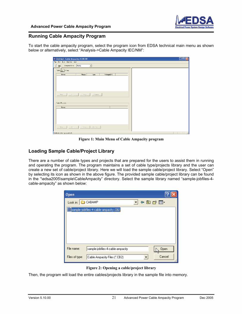
Running Cable Ampacity Program To start the cable ampacity program, select the program icon from EDSA technical main menu as shown below or alternatively, select “Analysis->Cable Ampacity IEC/NM”:
Loading Sample Cable/Project Librar There are a number of ca st them in running and operating the program library and the user can create a new set of cable/project librar le cable/project library. Select “Open”
Figure 1: Main Menu of Cable Ampacity program
y
ble types and projects that are prepared for the users to assi. The program maintains a set of cable type/projects
y. Here we will load the sampby selecting its icon as shown in the above figure. The provided sample cable/project library can be found in the “\edsa2005\sample\CableAmpacity” directory. Select the sample library named “sample-jobfiles-4-cable-ampacity” as shown below:
Figure 2: Opening a cable/project library
Then, the program will load the entire cables/projects library in the sample file into memory.
Advanced Power Cable Ampacity Program
Version 5.10.00 22 Advanced Power Cable Ampacity Program Dec 2005
As can be seen below, th er left hand side will list the available cable types library. The lo rary and right hand side will show either cable constru the highlighted row in the upper left hand side belo ct is the same as a study where the user seeks cabl n conditions.
e program window will have three parts. The uppwer left hand side, shows the projects lib
ction details (when a cable type is selected, notew) or cables locations in a highlighted project. A projees ampacity/temperature for a given cable installatio
Figure 3: Main Cable Menu after a cable/project library is loaded
Case Project Name
Provided Sample Projects Several sample cable types and sample projects have been prepared for the users convenience. The ollowing is a short description of the provided sample projects: f
Description
1 Sample for Dire LPE, Concentric Neutral
buried and the ampacity of the on unit daily load factors
ctly Buried Cables In this study, 3 single core XSubmarine Cables are directly cables are computed, cables have n
2 Sample for Cables duct cables are arranged
ct-bank. Ampacity of the on unit daily load factors
in Duct Bank Six 1000 KCMIL, XLPE, with PVC in two circuits and placed in a ducables are computed, cables have n
3 Sample frompaper
in the Neher McGrath s discussed extensively in
Neher-McGrath The 138 kV pipe type cable usedpaper is used in this study which ithis guide.
4 Sample for Dissi uses two different cable
per Insulated single Core core, 230kV cable.
milar Cables In this study we installation that types (dissimilar), one cable is PaCable and the other is a Pipe-type 3
5
Sample for Cables e as the one used in Concentric Neutral
example cables are riser ion is request and not
on Riser Pole This example uses the same cable typthe second study, i.e., the XLPE,Submarine Cable. However in thispole and the cable temperature calculatthe ampacity
Advanced Power Cable Ampacity Program
Version 5.10.00 23 Advanced Power Cable Ampacity Program Dec 2005
Step by Step Instructions for Adding a New Cable Type
t, or create a new roject. The same cable, make a
copy of an ex ady in the library point with mouse to row whe own above, then, either use the “Edit..” icon shown below:
The user can examine/delete an existing project, make a copy of an existing projecp options are also available for a cable, i.e., examine/delete an existing
isting cable, or create a new cable type. To edit a cable type alrere the desired cable is and with one left mouse click highlight it as sh
or double left mouse click will open the cable type dialogs as
Figure 4: Cable Type Dialogs
Several tabs are shown above each corresponding to different cable construction layers, e.g. Insulation, elow the dialog
r Sheath, Armor, etc. To edit any of the cable layers, simply select the corresponding tab. B
r the “Conductor” tab is shown (For example, in the figure below, cable conductor material can be eithefocopper, aluminum or can be defined by the user):
Advanced Power Cable Ampacity Program
Version 5.10.00 24 Advanced Power Cable Ampacity Program Dec 2005
Figure 5: Cable Conductor Dialog
Using the Drop-Down Menu Materials of each cable layers can be define by the user. Of course, there are many default materials
efined for each cable layer/section that the user can select. To choose an item from a dropdown menu, use the mo sulation material is shown as an example
duse to point to the dropdown arrow as shown below (here selection of cable in
) and left mouse click once on the “arrow”:
Figure 6: Selecting an Item from the Dropdown Menus
Advanced Power Cable Ampacity Program
Version 5.10.00 25 Advanced Power Cable Ampacity Program Dec 2005
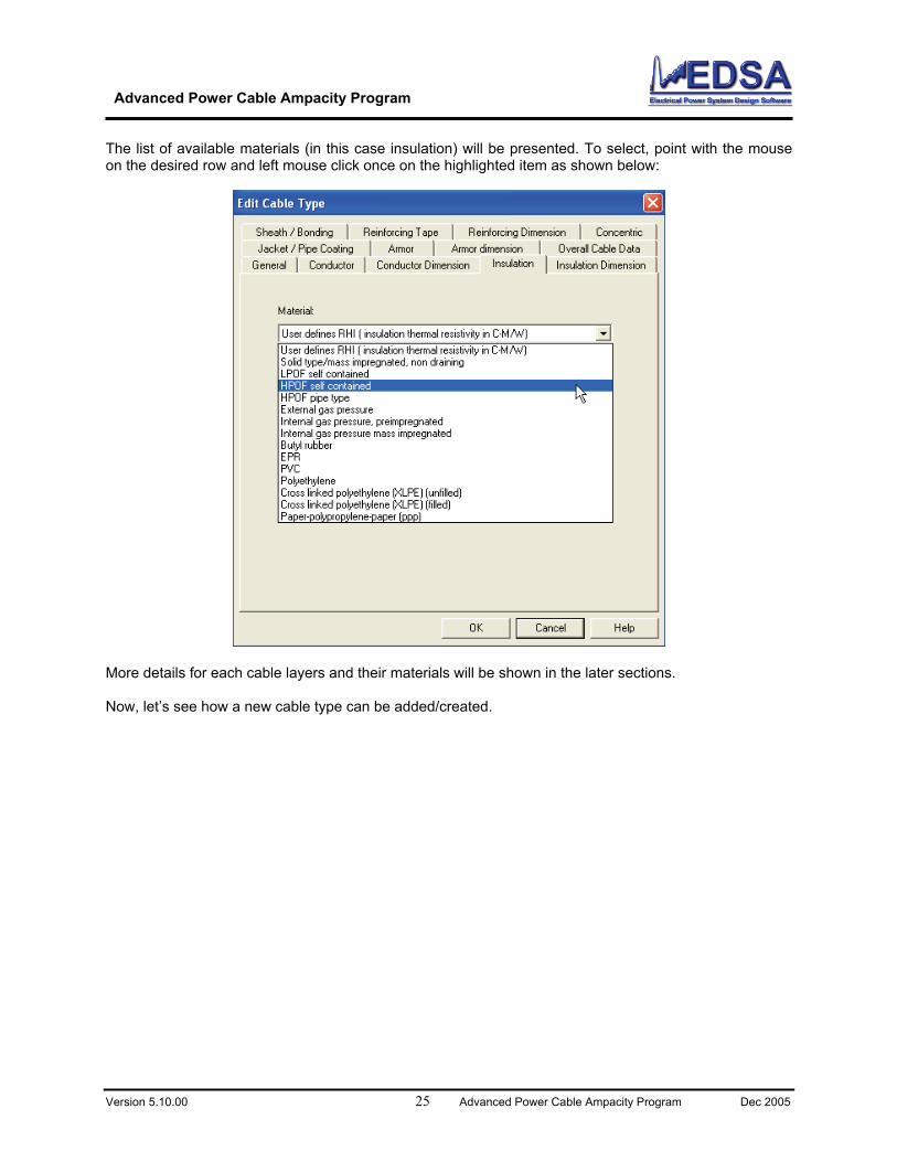
The list of available materials (in this case insulation) will be presented. To select, point with the mouse on the desired row and left mouse click once on the highlighted item as shown below:
More details fo Now, let’s see how a ne
r each cable layers and their materials will be shown in the later sections.
w cable type can be added/created.
Advanced Power Cable Ampacity Program
Version 5.10.00 26 Advanced Power Cable Ampacity Program Dec 2005
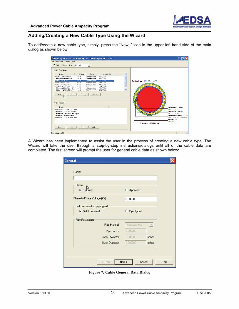
Adding/Creating a New Cable Type Using the Wizard To add/create a new e of the main dialog as shown bel
cable type, simply, press the “New..” icon in the upper left hand sidow:
A Wizard has be w cable type. The Wizard will ta l of the cable data are completed. The first scree :
en implemented to assist the user in the process of creating a neke the user through a step-by-step instructions/dialogs until al
n will prompt the user for general cable data as shown below
Figure 7: Cable General Data Dialog
Advanced Power Cable Ampacity Program
Version 5.10.00 27 Advanced Power Cable Ampacity Program Dec 2005
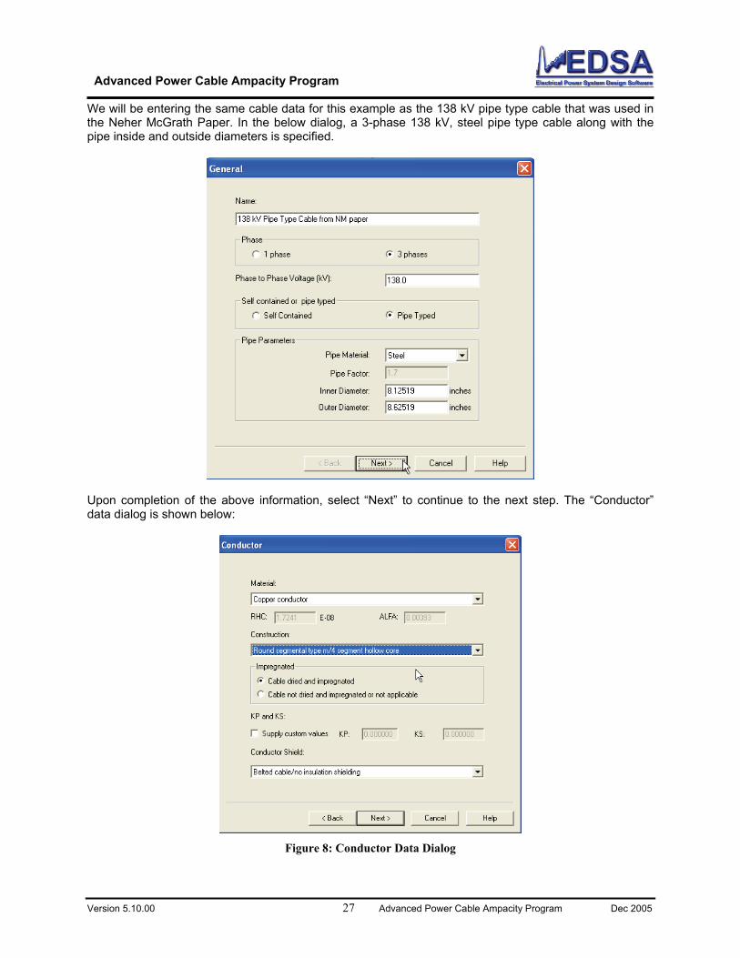
We will be entering the same cable data for this example as the 138 kV pipe type cable that was used in ong with the
ipe inside and outside diameters is specified.
the Neher McGrath Paper. In the below dialog, a 3-phase 138 kV, steel pipe type cable alp
Upon completion of the above in next step. The “Conductor” formation, select “Next” to continue to thedata dialog is shown below:
Figure 8: Conductor Data Dialog
Advanced Power Cable Ampacity Program
Version 5.10.00 28 Advanced Power Cable Ampacity Program Dec 2005
The cable construc Also, the conductor does not have any screen ted as shown below:
tion per Neher McGrath paper is a round 4-segmental cable./shield. Next, conductor dimension data dialog will be presen
Figure 9: Conductor Dimension Data Dialog
n area, diameter over conductor shield (if any) should be entereta based on the paper is shown in figure below.
The cable cross-sectio d in the above data dialog. The da
Advanced Power Cable Ampacity Program
Version 5.10.00 29 Advanced Power Cable Ampacity Program Dec 2005
The cable insulation data dialog will be shown next as seen in the figure below.
Figure 10: Cable Insulation Data Dialog
nd loss factors are all user defined for this example. The insulper is 5.5 ºC-m/W. This cable has no insulation shield/scre
The insulation material a ation thermal resistivity based on the pa en.
Advanced Power Cable Ampacity Program
Version 5.10.00 30 Advanced Power Cable Ampacity Program Dec 2005
sion data dialog will be the next data dialog that should be compleThe insulation dimen ted.
Figure 11: Cable Insulation Dimension Data Dialog
Advanced Power Cable Ampacity Program
Version 5.10.00 31 Advanced Power Cable Ampacity Program Dec 2005
The diameter over insulation and over insulation shield is the same in this case since we have no insulation shield.
In the next screen, d.
the cable sheath and bonding and transposition data should be provide
Figure 12: Cable Sheath Data Dialog
Advanced Power Cable Ampacity Program
Version 5.10.00 32 Advanced Power Cable Ampacity Program Dec 2005
to proceed to the next data dialog, i.e., the cable reinforcing data dialog as Select “Next” shown below:
Figure 13: Reinforcing Tape Data Dialog
Advanced Power Cable Ampacity Program
Version 5.10.00 33 Advanced Power Cable Ampacity Program Dec 2005
The reinforcin d in the Neher McGrath paper.
g tape made of brass/bronze is selected based on the data supplie
Figure 14: Reinforcing Tape Dimension Data Dialog
Advanced Power Cable Ampacity Program
Version 5.10.00 34 Advanced Power Cable Ampacity Program Dec 2005
g tape dimension data is entered next that is shown in the figure below: The reinforcin
The cable concen ble does not have any concentri
tric neutral or skid wire can be defined next. For the cable at hand, the cac neutral wires but it has a brass/bronze skid wire.
Advanced Power Cable Ampacity Program
Version 5.10.00 35 Advanced Power Cable Ampacity Program Dec 2005
Figure 15: Concentric Neutral/Skid Wire Data Dialog
The cable Jacket or in case of a pipe type cable, pipe coating material can be specified in the data dialog shown in the figure below:
Advanced Power Cable Ampacity Program
Version 5.10.00 36 Advanced Power Cable Ampacity Program Dec 2005
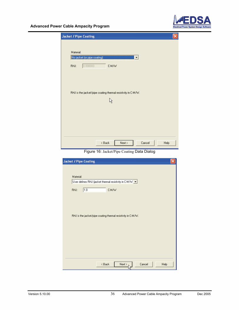
Figure 16: Jacket/Pipe Coating Data Dialog
Advanced Power Cable Ampacity Program
Version 5.10.00 37 Advanced Power Cable Ampacity Program Dec 2005
For this cable pipe coating is provided, i.e., RHJ
a user defined pipe coating material is selected where thermal resistivity of the= 1.0 ºC-m/W
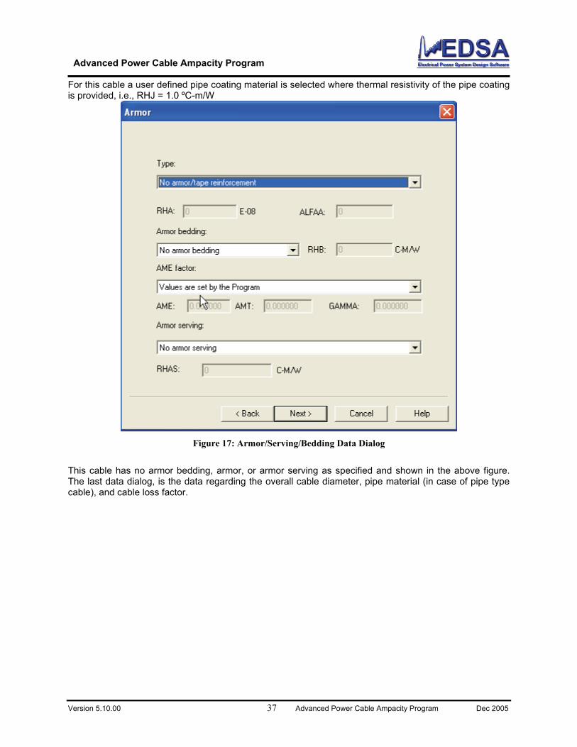
Figure 17: Armor/Serving/Bedding Data Dialog
This cable has no armor bedding, armor, or armor serving as specified and shown in the above figust data dialog, is the data regarding the overall cable diameter, pipe material (in case of pipe type
e), and cable loss factor.
re.
The la cabl
Advanced Power Cable Ampacity Program
Version 5.10.00 38 Advanced Power Cable Ampacity Program Dec 2005
Figure 18: Overall Cable Dimension Data Dialog
Advanced Power Cable Ampacity Program
Version 5.10.00 39 Advanced Power Cable Ampacity Program Dec 2005
After completing the overall cable dimension dialog, this cable that is just created will be added to
e/project library. As shown in the figure below, the newly added cable type is now can be seen ilist of available cable types.
the cabl n the
Advanced Power Cable Ampacity Program
Version 5.10.00 40 Advanced Power Cable Ampacity Program Dec 2005
Ho
o a n as show
w to Add/Create a Project/Study
T dd a new study/project select “New..” from the lower left hand side of the program’s main screen below:
Whe ns in
ne marked ble
g
n creating a new project/study, the program requires a number cable installation conditioaddition to the cables types and their location. In the next screen shown below, there are two tabs o
as “General” where general installation data can be entered and the other tab named “CaInstallation” where cable type and location can be specified.
First the general project data should be completed. The general data requirement is show the dialoillustrated in the figure below:
Advanced Power Cable Ampacity Program
Version 5.10.00 41 Advanced Power Cable Ampacity Program Dec 2005
In the above there are several groups of data which is required. These are:
easy reference in the future.
Soil resistivity and ambient temperature
Computation option: program can compute ampacity of cables given their maximum operating temperature or alternaively, program can compute temperature if cable ampacities are given.
Solution method can be either IEC or Neher McGrath. If all of the cables have unity daily load factor, then, IEC is the recommended method, otherwise, Neher McGrath should be selected
Study/Project Title: The user is recommended to assign an identification record to each study for
Advanced Power Cable Ampacity Program
Version 5.10.00 42 Advanced Power Cable Ampacity Program Dec 2005
Cables can be in air, buried directly, being in backfill or ductbank
Heat source/sink data in any adjacent to the cables
Duct dimension and material
Non-iso thermal earth surface simulation
And finally if the program should include soil drying out condition
Figure 19: Project/Study General Data Dialog
Advanced Power Cable Ampacity Program
Version 5.10.00 43 Advanced Power Cable Ampacity Program Dec 2005
The gen ow screen:
eral installation data entered based on the Neher McGrath paper is shown in the bel
After completing the tified. Use the mouse to select the “Cable Install shown below.
“General” data, the cable locations and type needs to be idenation” tab as shown above. The data dialog appears in the figure
Advanced Power Cable Ampacity Program
Version 5.10.00 44 Advanced Power Cable Ampacity Program Dec 2005
t mouse
To add a cable type to the study, use the mouse to point to “Add Cable..” icon and then click once the lef button.
Figure 20: Adding a Cable to a Study/Project
Advanced Power Cable Ampacity Program
Version 5.10.00 45 Advanced Power Cable Ampacity Program Dec 2005
In the data dialog shown below, first we should specify which cable is to be used in the study. Press “Select Cable..” icon as shown below to see a list of available cables in the library.
cables in the library are shown in the figure below. Simply, use the mouse to highlight the dee and then press “OK” button to accept the selection. In the case at hand we will choose the cableted in the previous section “138 kV Pipe Type Cable from NM paper”.
List of sired cabl we crea
Figure 21: Selecting a Cable om the Cable Type Library fr
Advanced Power Cable Ampacity Program
Version 5.10.00 46 Advanced Power Cable Ampacity Program Dec 2005
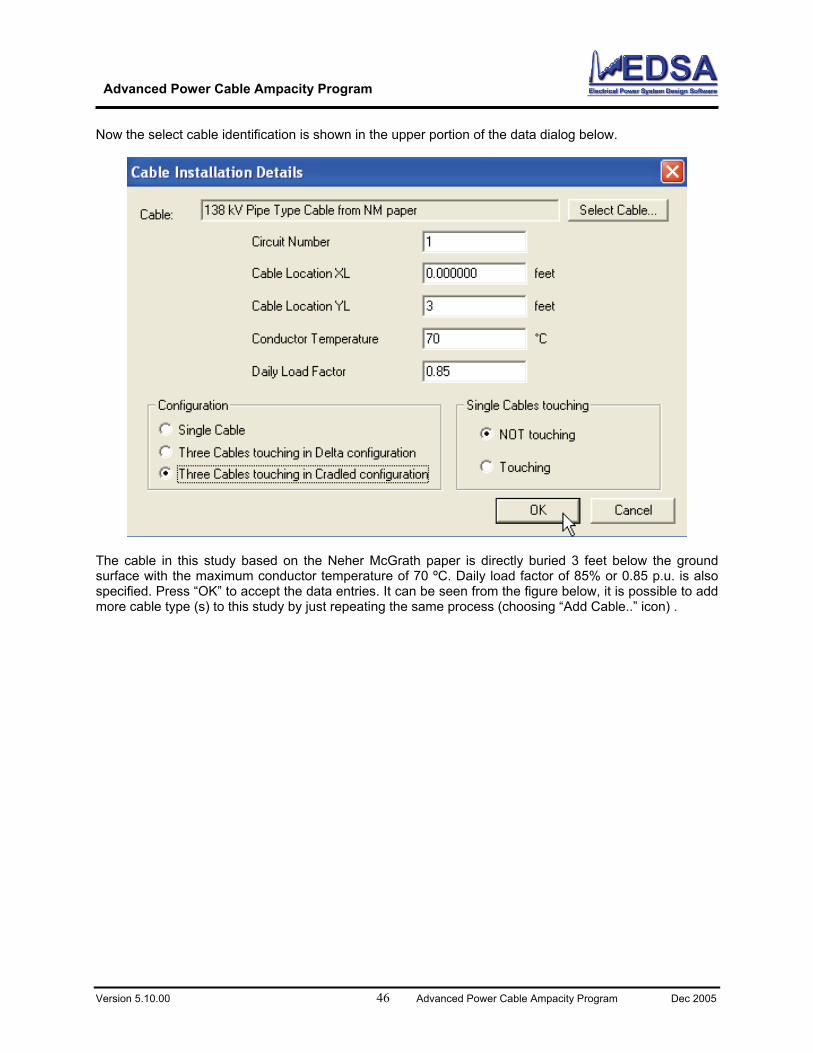
Now the select cable identification is shown in the upper portion of the data dialog below.
The cable in this study based on the Neher McGrath paper is directly buried 3 feet below the ground surface with the maximum conductor temperature of 70 ºC. Daily load factor of 85% or 0.85 p.u. is also specified. Press “OK” to accept the data entries. It can be seen from the figure below, it is possible to add more cable type (s) to this study by just repeating the same process (choosing “Add Cable..” icon) .
Advanced Power Cable Ampacity Program
Version 5.10.00 47 Advanced Power Cable Ampacity Program Dec 2005
Since there is no additional cable in this study, press “OK” to complete study/project data .
Advanced Power Cable Ampacity Program
Version 5.10.00 48 Advanced Power Cable Ampacity Program Dec 2005
n the list of existing studies as shown in the lower left hand The study is just created is now can be seen iside of the figure shown below:
he ampacity to point to the of the above
new project to se the “Run-. Once this is port browser
How to Run a Simulation Now that we have completed all the necessary data for the cable installation conditions, tcomputation can be performed. To start the ampacity calculation, first use the mouse desired study in the list of existing studied/projects as shown in the lower left hand sidescreen. For example, in the above screen in the list of studies, the study named “This is ause newly created pipe type cable” is highlighted. Now that the study is selected choo>Project Calculation” option from the menu bar shown at the top portion of the above figureselected the program will start the ampacity computation and will show the result in the rewindow that is shown below:
Advanced Power Cable Ampacity Program
Version 5.10.00 49 Advanced Power Cable Ampacity Program Dec 2005
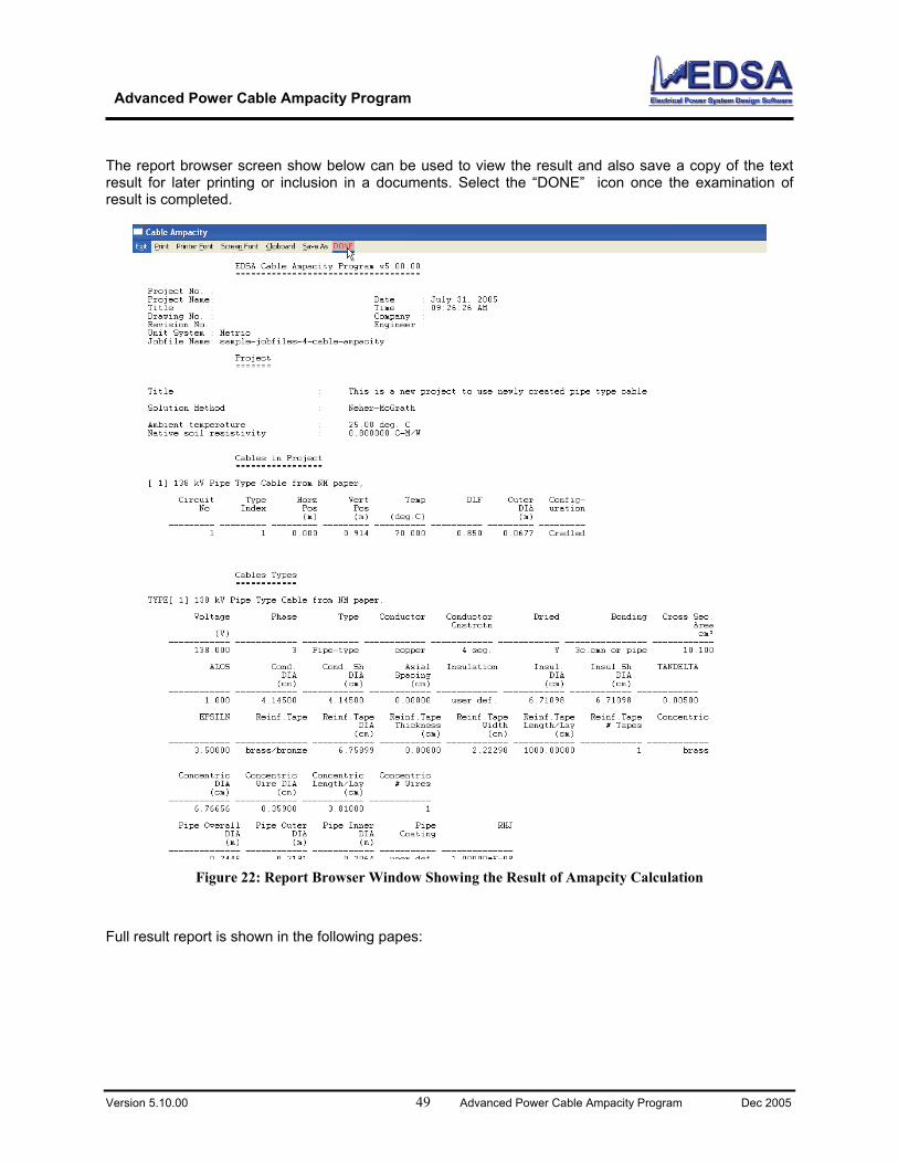
report browser screen show below can be used to view the result and also save a copy of the text sult for later printing or inclusion in a documents. Select the “DONE” icon once the examination of
result is completed.
The re
Full u
Figure 22: Report Browser Window Showing the Result of Amapcity Calculation
res lt report is shown in the following papes:
Advanced Power Cable Ampacity Program
Version 5.10.00 50 Advanced Power Cable Ampacity Program Dec 2005
EDSA Cable Ampacity Program v5.00.00 ==================================== Project No. : Project Name: Date : July 29, 2005 Title Time : 12:42:3 M : 8 P Drawing No. : Company : Revision No.: Engineer : Unit System : U.S. Standard Jobfile Name: sample-jobfiles-4-cable-ampacity Project ======= Ti tle : This is a new project to use newly created pipe type cable Solution Method : Neher-McGrath Ambient temperature : 25.00 deg. C Native soil resistivity : 0.800000 C-M/W Cables in Project ================= [ 1] 138 kV Pipe Type Cable from NM paper, Circuit Type Horz Vert Temp DLF Outer Config- No. Index Pos Pos DIA uration (ft) (ft) (deg.C) (ft) --------- --------- --------- --------- ---------- ---------- --------- --------- 1 1 0.000 3.000 70.000 0.850 0.2220 Cradled Cables Types ============ TYPE[ 1] 138 kV Pipe Type Cable from NM paper, Voltage Phase Type Conductor Conductor Dried Bonding Cross Sec. Cnstrctn Area (V) in² ------------ ------------ ----------- ------------ ------------ ------------ ---------------- ------------ 138.000 3 Pipe-type copper 4 seg. Y 3c.cmn or pipe 1.566 ALOS Cond. Cond. Sh Axial Insulation Insul. Insul.Sh TANDELTA DIA DIA Spacing DIA DIA (in) (in) (in) (in) (in) ------------ ------------ ------------ ------------ ------------ ------------ ------------ ------------ 1.000 1.63189 1.63189 0.00000 user def. 2.64212 2.64212 0.00500 EPSILN Reinf.Tape Reinf.Tape Reinf.Tape Reinf.Tape Reinf.Tape Reinf.Tape Concentric DIA Thickness Width Length/Lay # Tapes (in) (in) (in) (in) ------------ -------------- ------------ ------------ ------------ ------------ ------------ ------------ 3.50000 brass/bronze 2.66102 0.00315 0.87519 0.98425 1 brass Concentric Concentric Concentric Concentric DIA Wire DIA Length/Lay # Wires (in) (in) (in) ------------ ------------ ------------ ------------ 2.66400 0.14134 1.50000 1 Pipe Overall Pipe Outer Pipe Inner Pipe RHJ DIA DIA DIA Coating (ft) (ft) (ft) -------------- ------------ ------------ ----------- -------------- 0.8022 0.7188 0.6771 user def. 1.00000*E-08 Cable Ampacity Results ====================== This is a new project to use newly created pipe type cable Solution converged after 4 iterations Cable No X Location Y Location Cond. Temp. Ampacity Ft Ft (Deg.C) (AMPS)
Advanced Power Cable Ampacity Program
Version 5.10.00 51 Advanced Power Cable Ampacity Program Dec 2005
1 0.00 3.00 70. 904.
Pro a The cacomThe cadiamete
gr m Validation and Verification
ble ampacity program has been used numerous to assess its validity. In this section we will pare the result of this program against the result for a pipe type cable in the Neher McGrath paper.
ble is a 138 kV - 2000 KCMIL High-Pressure Oil-Filled Pipe-type Cable in 8.625 inch outside r pipe. The Cable shielding consists of an intercalated 7/8 × 0.003 inch bronze tape with 1 inch lay ingle 0.1 × 0.2 inch D shaped brass skid wire having 1.5 inch lay. Thand a s
conresisti ipag 5
e cables will lie in cradled figuration. The pipe is located 36 inches (3 feet) below the earth surface in soil having thermal
ty of 0.85 K.m/W. An ambient temperature of 25 ºC is assumed. Thv is problem is chosen from e 2 of the Neher McGrath paper and cable cress section as well as dimensions are shown below:
Figure 23: 138 kV, 2000 MCM high pressure oil-filled, 3-conductor, pipe type cable.
Outside diameter of sheath (DS) - 2.661” = 67.589 mm.
Inside diameter of pipe (DP) - 8.125” = 206.375 mm.
Outside diameter of pipe (DPO) - 8.625” = 219.075 mm. The EDSA cable ampacity program for the above case produces versy close result as those reported in the IEEE paper as summarized below:
Advanced Power Cable Ampacity Program
Version 5.10.00 52 Advanced Power Cable Ampacity Program Dec 2005
Table 1: Comparing Results of Neher McGrath and EDSA’s Cable Ampacity Program
Reference Neher McGrath IEEE Paper EDSA’s Cable Ampacity Program Cable Ampacity (amp) 905 904
Error (%) - 0.1
posium on Temperature Rise of Cables," Vol. 72, Part II, p. 530-62, 1953.
mittee Report, "A-C Resistance of Pipe-Cable Systems with Segmental Conductors," rt III, p. 393-414, 1952.
-135-1, Power Cable Ampacity Tables, ICES Publication, pp. 46-426, 1962.
oximity Effect in Solid and ow Round Conductors," Journal IEE, Vol. 88, 941.
Arnold, A.H. sulated Lead-Covered Cables, Armored and Unarmo Journal IEE, Vol. 88, Part I, p. 52-63, Feb., 1941.
the issue of maximum allowable ampacity strictly from the point f view of the cable and system l aracteristics. In other words, they are generally limited to factors
op. In reality, cable ampacity is a much more complex concept
he allo able conducto sed is the main factor that defines e amp city of a cable. lem requires the integration of all aspects of
Cab
Environment
Traditional cable sizing methods addresso oad chsuch as insulation rating and voltage drthat hinges on many other factors.
ion being uT w r temperature for the type of insulata A complete approach to the probth
cable system design such as:
Load characteristics
le type
Conductor material & size
Insulation thickness and properties
Shield connections
Installation conditions
Figure 24: Basic Thermal Circuit
Of course, other system conditions and load-flow characteristics may limit the rating of the cable to values lower than its ampacity. The basic calculation procedure for studying the thermal behavior of an element corresponds to the thermal equivalent of Ohm's law, which is shown in above Figure. Here we can see that Heat (Watts) is equivalent to electrical current, and Thermal Resistance (thermal ohm-foot) corresponds to electrical resistance (ohms). When heat circulates through the circuit's thermal resistance, a temperature drop ( C° ) is established. Thermal resistance values depend on material properties, thermal resistivity, and geometric characteristics.
Advanced Power Cable Ampacity Program
Version 5.10.00 55 Advanced Power Cable Ampacity Program Dec 2005
hermal resistivity is defined in units of wattcmC /−° for both, the metric and imperial systems. In e significance of this unit, consider the
llowing: a material that possesses a resistivity of wattcmC /1
TEurope, however, is defined as wattmC /−° . To illustrate th
−fo ° , will experience a C°1 temperature se when a heat flow equivalent to 1 2/ cmwatt flows through a 1 cm section of the material.
Figure 25: Definition of Thermal-Ohm Units
ri
1 Watt
dT = 1oC
1 Foot(1Meter)
1 Thermal Ohm-Foot(1 Thermal Ohm-Meter)
In the United States, the ampacity calculations are based on a unit cable length of 1 foot, thus defining a Thermal-Ohm-Foot (TOF) ( watt/footC−° ) as the thermal resistance that causes a C1° -temperatureincrease, when 1 watt of heat per foot of conductor is generated. The equivalent metric unit is called theThermal Ohm Meter (TOM), and is expressed as ( watt/mC−° ). The above Figure illustrates theconcept of Thermal-Ohm-Foot/Meter.
Figure 26: Mathematical Model of a Cable Thermal Circuit Figure above, illustrates a mathematical model that describes the thermal circuit of a self-cooled buried transmission cable. This model is typical of a pipe-type cable system, which is one of the most common types of cable used in transmission applications. While conventional models may include conductor and dielectric losses and maybe even shield effect, they fail to take into account crucial thermal elements such as pipe fluid, and earth losses. Each of the components are summarized as follows:
Version 5.10.00 56 Advanced Power Cable Ampacity Program Dec 2005
Temperatures: Conductor Cable/earth interface Ambient Losses: Ohmic ( )RI2 ∗ Dielectric (insulation) Shield/sheath (eddy & circulating currents) Pipe (edddy-current & hysteresis ) Thermal Resistance: Electrical insulation Dielectric Pipe covering Earth Mutual heating effect of nearby heat sources (steam mains) Mutual heating effect of other nearby cable systems Shield - Fluid Fluid - Pipe Duct material Air space Concrete envelope Thermal Capacitance: Conductors Insulation Shield Fluid
the tempeelementmethod
Nehe
287 mbetter treatment of sheath losses for single conductor cables. Both methods are applicable to both single and three-conductor cable in various installations, such as cable in air, cable in duct, and cable buried in earth.
Pipe Earth
In the particular case of cables in free air, one must consider the effect of solar radiation, which increases rature rise, and the effect of the wind, which decreases it. As seen from the above list of
s, the true ampacity of a cable depends on many factors, which are often ignored by traditional s. This leads to poor/dangerous design specifications.
Virtually every steady-state ampacity calculation in the United States is performed according to the r-McGrath method. This procedure quantifies with extreme accuracy the added heating effect
imposed by each and every one of the elements previously listed. A non-US practice is to employ the IEC ethod, which is the metric equivalent to the Neher-McGrath procedure. IEC 287, however, has a
Advanced Power Cable Ampacity Program
Version 5.10.00 57 Advanced Power Cable Ampacity Program Dec 2005
APPENDIX II: Some Useful Diagrams and Figures Cable type: Pipe / Location: In Air
Air AirConduit/Pipe
Pipe Type Cable
Advanced Power Cable Ampacity Program
Version 5.10.00 58 Advanced Power Cable Ampacity Program Dec 2005
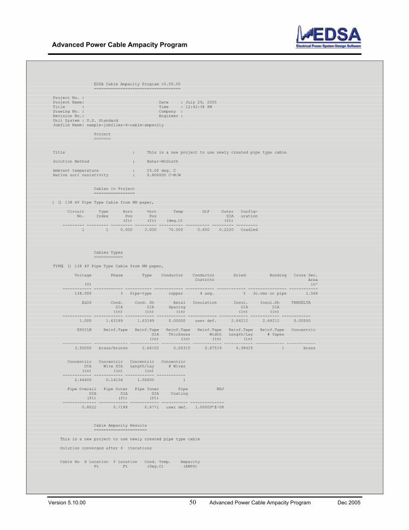
Cable type: Pipe / Location: Buried
Soil
Soil
Advanced Power Cable Ampacity Program
Version 5.10.00 59 Advanced Power Cable Ampacity Program Dec 2005
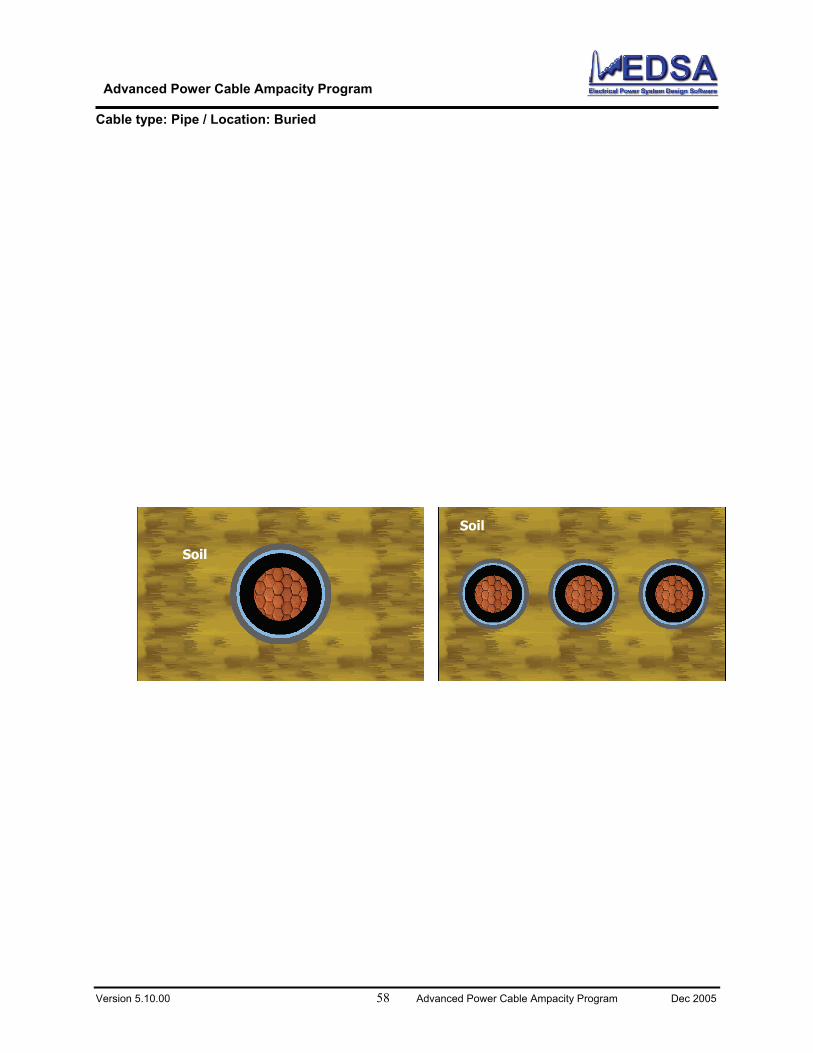
Cable type: Duct / Location: Air
Air Air
Duct Bank
Duct Bank
Ground Surface
Ground Surface
Advanced Power Cable Ampacity Program
Version 5.10.00 60 Advanced Power Cable Ampacity Program Dec 2005
Cable type: Duct / Location: Buried
Soil
Ground Surface
Duct Bank
Advanced Power Cable Ampacity Program
Version 5.10.00 61 Advanced Power Cable Ampacity Program Dec 2005
Cable type: No Pipe - No Duct / Location: Buried
Soil Soil
Advanced Power Cable Ampacity Program
Version 5.10.00 62 Advanced Power Cable Ampacity Program Dec 2005
Cable Construction Type
OIL
Triplex Configuration
Single conductor Oil-filled cable
Configuration Cradle
3-Conductor Cables in Duct
Cables in flat configuration
Advanced Power Cable Ampacity Program
Version 5.10.00 63 Advanced Power Cable Ampacity Program Dec 2005
Magnetic Armor or Reinforcement Type
Non-Magnetic Armor 3-Conductor Cables.
Magnetic pipe/conduit 3-Conductor Cables.
Magnetic pipe/conduit 1-Conductor Close Triangular Cables.
Magnetic pipe/conduit 1-Conductor Cradled Cables.
Non-Magnetic Armor 1-Conductor Close Triangular Cables.
Non-Magnetic Armor 1-Conductor Cradled Cables.
Advanced Power Cable Ampacity Program
Version 5.10.00 64 Advanced Power Cable Ampacity Program Dec 2005
Thermal Circuit Type
Two Core Belted Circular Conductor
Three Core Belted Circular Conductor
Advanced Power Cable Ampacity Program
Version 5.10.00 65 Advanced Power Cable Ampacity Program Dec 2005
Conductor Shield/Screen and Jacket
Conductor
InsulationJacket
tC
ti
DJ
Advanced Power Cable Ampacity Program
Version 5.10.00 66 Advanced Power Cable Ampacity Program Dec 2005
Insulation
Armo
Jacket
Belt fo
Core (t
r, Binder for RI (tai)
r RI (tbi)
ci)
Advanced Power Cable Ampacity Program
Version 5.10.00 67 Advanced Power Cable Ampacity Program Dec 2005
Conductor Material
Figure 27: C le Top l Pa meters Self Contained Cables
he figu omplete cable es the general range of the information quired
ab ology / Genera ra
T re above is a c topology, which outlinre for a typical cable ampacity calculation.
Figure 28: Typical Pipe Cable Cross-Section
Conductor Shield
Insulation Type
Insulation Shield
Sheath Type
Concentric Wires
Sheath Reinforcing Material
Armour Bedding
Armour Type
External Cover
Advanced Power Cable Ampacity Program
Version 5.10.00 68 Advanced Power Cable Ampacity Program Dec 2005
Configuration of Cable in the Duct/Conduit:
9: Configuration of Ca ct/Conduit Figur 2 ble in the Due
Figure 30: Ductbank G Factorb
Advanced Power Cable Ampacity Program
Version 5.10.00 69 Advanced Power Cable Ampacity Program Dec 2005
APPENDIX III: Tables of Material Properties
n selec ductive capacitance
of Insu
Materials Insulation (εr)
Polyethylene Paper Insulation (Solid ty
3 - 4.2
The user has the option to select e its protective coverings, and the
ρ in Ccm/watt Paper Insulation (Solid type) 700 (IPCEA Value)
Varnished Cambric Paper Insulation (other types)
thermal r needs
Table 4: Pipe Constants Condition A’ B’ In Metallic Conduit 3.2 0.190
In Fiber Duct in Air 5.6 0.330 In Fiber Duct in Concrete 4.6 0.270 In Transite Duct in Air 4.4 0.260 In Transite Duct in Concrete 3.7 0.220 Gas - Filled Pipe Cable at 200 psi 2.1 0.680 Oil - Filled Pipe Cable 2.1 2.450
Different types of insulating material are listed below. The user ca t specific inof insulation (εr) based on the type of cable.
Table 2: Specific Inductive Capacitance lation
2.3 pe) 3.7 (IPCEA Value)
Paper Insulation (Other type) 3. Rubber and Rubber-like compounds 5.0 (IPCEA Value) Varnished Cambric 5.0 (IPCEA Value) The thermal resistivities of different materials are listed in table below.the material thermal resistivities depending on the typ of cable,
aterials for duct installations. m
Table 3: Thermal Resistivity of Various Materials Material
600 (IPCEA Value) 500 - 550
Rubber and Rubber-like 500 (IPCEA Value) Jute and Textile Protective Covering 500
Duct 480 Fiber Polyethylene 450 Transite duct 200 Somastic (Jacket) 100 Concrete 85 For cables in ducts or pipes, the constants A' and B' from below table are used for calculation ofresistance (R ) of the air space between the cable surface and the duct internal surface. The useSD
e e cable. to supply the values of the constants from table below dep nding on the installation of th
Advanced Power Cable Ampacity Program
Version 5.10.00 70 Advanced Power Cable Ampacity Program Dec 2005
Table 5: Conductor Material
Material Resistivity ( ρ )ohm.m @ 20 ºC. TemperatureCoefficient (δ B20B) per K at 20 ºC
Copper 1.7241 x 10⁸−
3.93 x 10³−
Aluminum 2.8264 x 10⁸−
4.03 x 10³−
Lead or Lead Alloy 21.4 x 10⁸−
4.0 x 10³−
Steel 13.8 x 10⁸−
4.5 x 10³−
Bronze 3.5 x 10⁸−
3.0 x 10³−
Stainless Steel 70.0 x 10⁸−
Negligible
Aluminum 2.84 x 10⁸−
4.03 x 10³−
Brass 6.24 x 10⁸−
4.5 x 10³−
Table 6: Dielectric Loss
Types of cables U BoB (kV) (line to ground) Cables insulated with impregnated paper 30 Cables with other kinds of insulation: Butyl rubber 15 EPR 15 PVC 6 PE 110 XLPE 45
Table 7: Resistivities of Materials Material Thermal resistivity (K.m/W) Paper insulation in solid type cables 6.0 Paper insulation in oil-filled cables 5.0 Paper insulation in cables with external gas pressure 5.5 Paper insulation in cables with internal gas pressure: a. Pre impregnated 6.5 b. Mass impregnated 6.0 PE 3.5 XLPE 3.5 Polyvinyl chloride: up to and including 3 kV cables 5.0 greater than 3 kV cables 6.0 EPR: up to and including 3 kV cables 3.5 greater than 3 kV cables 5.0 Butyl rubber 5.0 Rubber 5.0 Protective coverings: Compounded jute and fibrous materials 6.0 Rubber sandwich protection 6.0 Polychloroprene 5.5 PVC: up to and including 35 kV cables 5.0 greater than 35 kV cables 6.0 PVC/bitumen on corrugated aluminum sheaths 6.0 PE 3.5
Advanced Power Cable Ampacity Program
Version 5.10.00 71 Advanced Power Cable Ampacity Program Dec 2005
Materials for duct installations: Concrete 1.0 Fibre 4.8 Asbestos 2.0 Earthenware 1.2 PVC 7.0 PE 3.5
Table 8: Absorption Coefficients of Solar Radiation Materials Absorption Coefficients ⎯⎯⎯⎯⎯⎯⎯⎯⎯⎯⎯⎯⎯⎯⎯⎯⎯⎯⎯⎯⎯⎯ Bitumen/Jute serving 0.8 Polychloroprene 0.8 Polyvinylchloride (PVC) 0.6 Polyethylene (PE) 0.4 Lead of Armor 0.6 For the cable diameters in the range of 25 mm to 100 mm, the constants UU, V and Y in following tbale are used for calculation of thermal resistance of the air space between the cable surface and the duct internal surface.
Table 9: Constants For Ducts Or Pipes Installation condition UU V Y B2 B B B
⎯⎯⎯⎯⎯⎯⎯⎯⎯⎯⎯⎯⎯⎯⎯⎯⎯⎯⎯⎯⎯⎯⎯⎯⎯⎯⎯⎯⎯⎯ In metallic conduit 5.2 1.4 0.011 In fibre duct in air 5.2 0.83 0.006 In fibre duct in concrete 5.2 0.91 0.010 In asbestos cement: duct in air 5.2 1.2 0.006 duct in concrete 5.2 1.1 0.011 Gas pressure cable in pipe 0.95 0.46 0.0021 Oil pressure pipe type cable 0.26 0.0 0.0026 Plastic ducts Under consideration by IEC Earthenware ducts 1.87 0.28 0.0036


![Cable Ampacity Tables for Direct Current Traction Power ... · PDF fileCable Ampacity Tables for Direct Current Traction Power Systems ... the Neher-McGrath Model [2]. ... Cable Ampacity](https://static.documents.pub/doc/80x56/5a70118e7f8b9a93538ba0d5/cable-ampacity-tables-for-direct-current-traction-power-nbsppdf.jpg)