1. 目的 (Purpose): CABLINE-UY PLUG における、ケーブルの半田付け手順及び SHELL A の組み付けについて明記する。 This manual is to explain the soldering method / process of the CABLINE-UY PLUG with cable, and assembly of SHELL A.
2. 適用コネクタ (Applicable connector): Name: CABLINE-UY PLUG Parts No. :
Set P/N CABLE ASS’Y 20857
Discrete P/N HOUSING ASS’Y 20907-0**E-01
SHELL A 3568-0**1
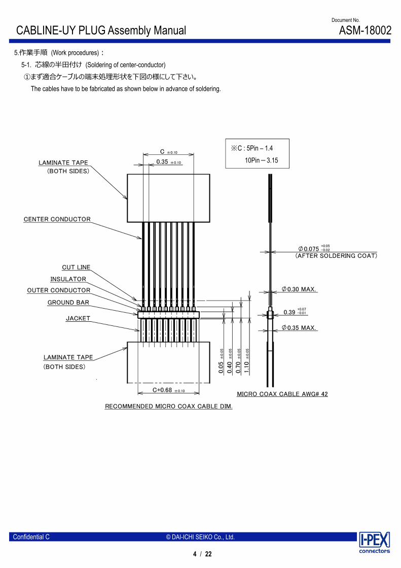
** : 05 = 5P , 10 = 10P
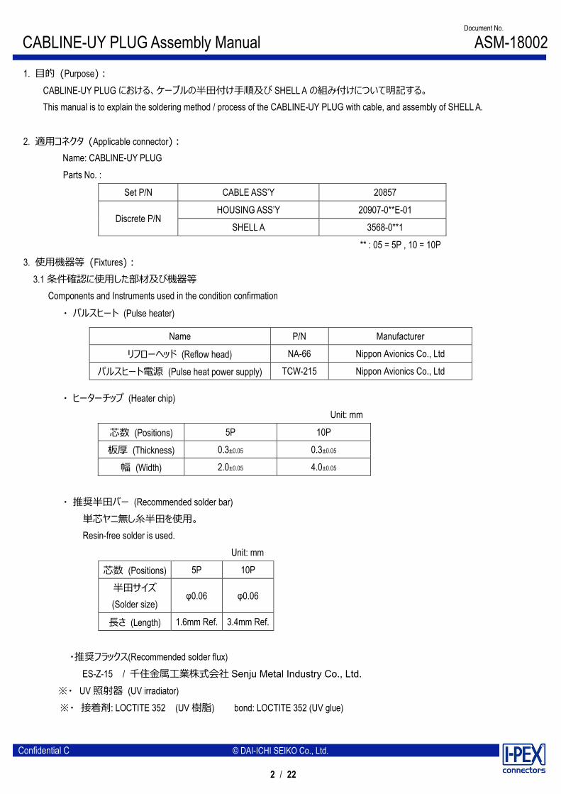
3. 使用機器等 (Fixtures): 3.1 条件確認に使用した部材及び機器等 Components and Instruments used in the condition confirmation
・ パルスヒート (Pulse heater)
・ ヒーターチップ (Heater chip) Unit: mm
・ 推奨半田バー (Recommended solder bar) 単芯ヤニ無し糸半田を使用。
Resin-free solder is used. Unit: mm
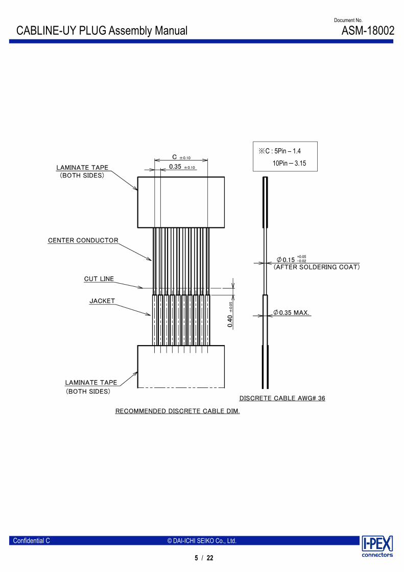
芯数 (Positions) 5P 10P
半田サイズ (Solder size)
φ0.06 φ0.06
長さ (Length) 1.6mm Ref. 3.4mm Ref.
・推奨フラックス(Recommended solder flux) ES-Z-15 / 千住金属工業株式会社 Senju Metal Industry Co., Ltd.
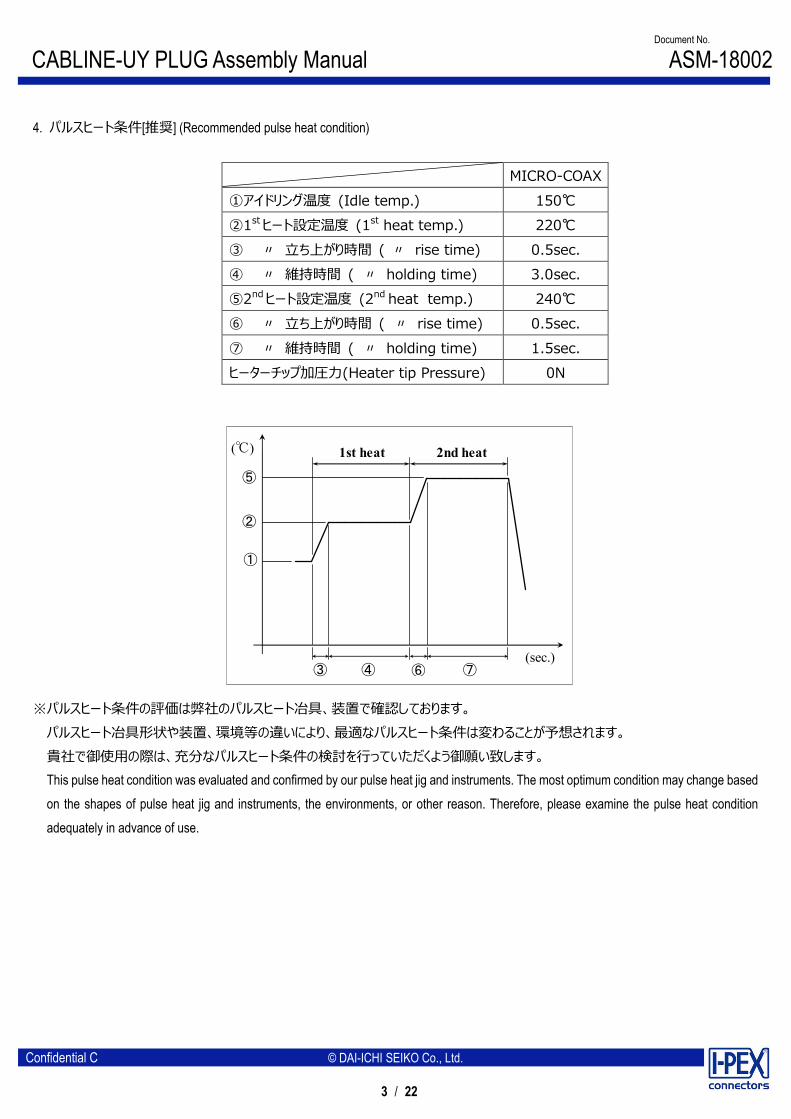
※パルスヒート条件の評価は弊社のパルスヒート冶具、装置で確認しております。 パルスヒート冶具形状や装置、環境等の違いにより、最適なパルスヒート条件は変わることが予想されます。 貴社で御使用の際は、充分なパルスヒート条件の検討を行っていただくよう御願い致します。 This pulse heat condition was evaluated and confirmed by our pulse heat jig and instruments. The most optimum condition may change based on the shapes of pulse heat jig and instruments, the environments, or other reason. Therefore, please examine the pulse heat condition adequately in advance of use.
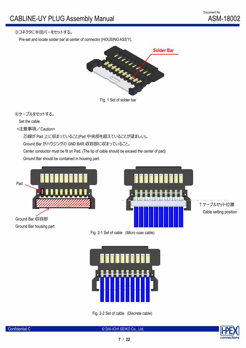
②ディスペンサー等でコンタクトにフラックスを塗布し、全コンタクトにフラックスが塗布されたことを確認して下さい。 Apply flux to contact by the dispenser etc., and please confirm all contacts were applied flux.
※Please do not apply flux too much as shown in Photo.2. It may cause flux splash or leak to the mating area.
Photo. 2 Extra flux
※フラックスの塗布が過多になり修正が必要な場合は、フラックスが嵌合部に付着しないように取り除いてください。 ※If flux applied too much and modification is needed, please remove excessive flux so that flux does not adhere to mating area.
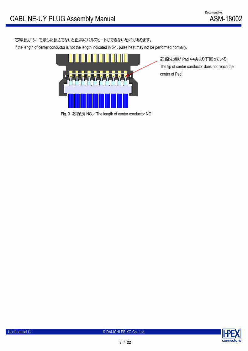
芯線長が 5-1 で示した長さでないと正常にパルスヒートができない恐れがあります。 If the length of center conductor is not the length indicated in 5-1, pulse heat may not be performed normally.
芯線先端が Pad 中央より下回っている The tip of center conductor does not reach the center of Pad.
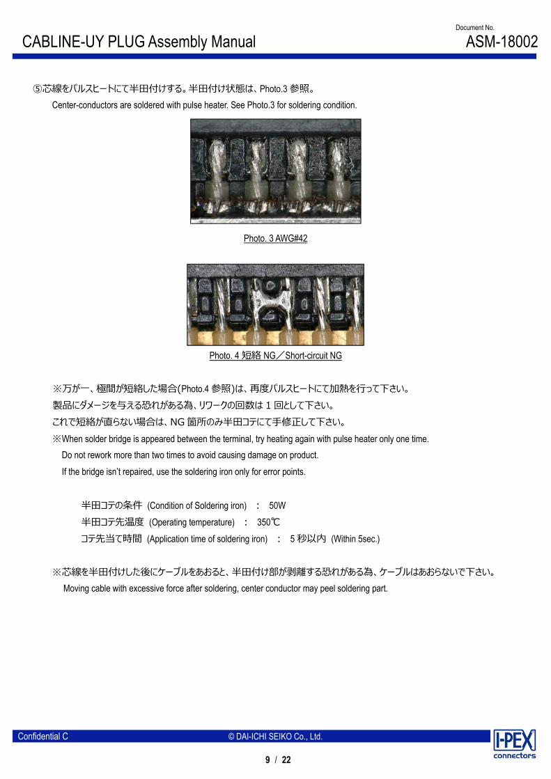
⑤芯線をパルスヒートにて半田付けする。半田付け状態は、Photo.3 参照。 Center-conductors are soldered with pulse heater. See Photo.3 for soldering condition.
Photo. 3 AWG#42
Photo. 4 短絡 NG/Short-circuit NG
※万が一、極間が短絡した場合(Photo.4 参照)は、再度パルスヒートにて加熱を行って下さい。 製品にダメージを与える恐れがある為、リワークの回数は 1 回として下さい。 これで短絡が直らない場合は、NG 箇所のみ半田コテにて手修正して下さい。 ※When solder bridge is appeared between the terminal, try heating again with pulse heater only one time. Do not rework more than two times to avoid causing damage on product.
If the bridge isn’t repaired, use the soldering iron only for error points.
半田コテの条件 (Condition of Soldering iron) : 50W 半田コテ先温度 (Operating temperature) : 350℃ コテ先当て時間 (Application time of soldering iron) : 5 秒以内 (Within 5sec.)
※芯線を半田付けした後にケーブルをあおると、半田付け部が剥離する恐れがある為、ケーブルはあおらないで下さい。 Moving cable with excessive force after soldering, center conductor may peel soldering part.
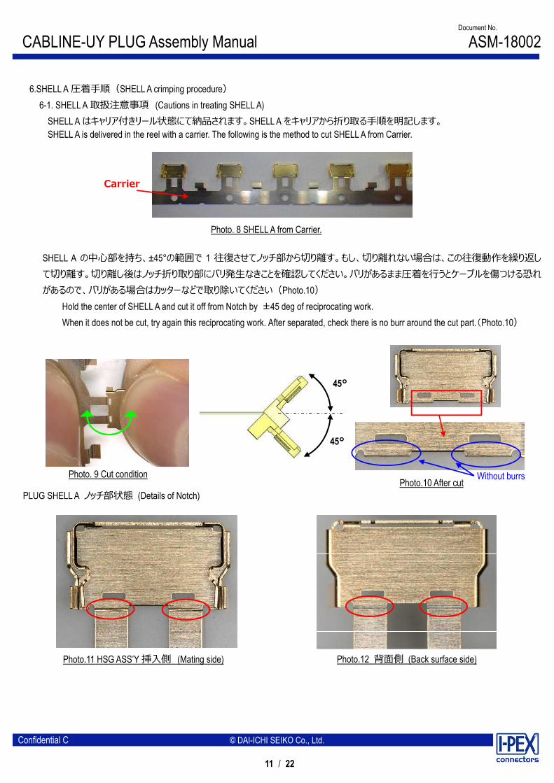
6-1. SHELL A 取扱注意事項 (Cautions in treating SHELL A) SHELL A はキャリア付きリール状態にて納品されます。SHELL A をキャリアから折り取る手順を明記します。 SHELL A is delivered in the reel with a carrier. The following is the method to cut SHELL A from Carrier.
SHELL A の中心部を持ち、±45°の範囲で 1 往復させてノッチ部から切り離す。もし、切り離れない場合は、この往復動作を繰り返して切り離す。切り離し後はノッチ折り取り部にバリ発生なきことを確認してください。バリがあるまま圧着を行うとケーブルを傷つける恐れがあるので、バリがある場合はカッターなどで取り除いてください(Photo.10)
Hold the center of SHELL A and cut it off from Notch by ±45 deg of reciprocating work. When it does not be cut, try again this reciprocating work. After separated, check there is no burr around the cut part.(Photo.10)
PLUG SHELL A ノッチ部状態 (Details of Notch)
Photo. 8 SHELL A from Carrier.
Photo. 9 Cut condition Photo.10 After cut Without burrs
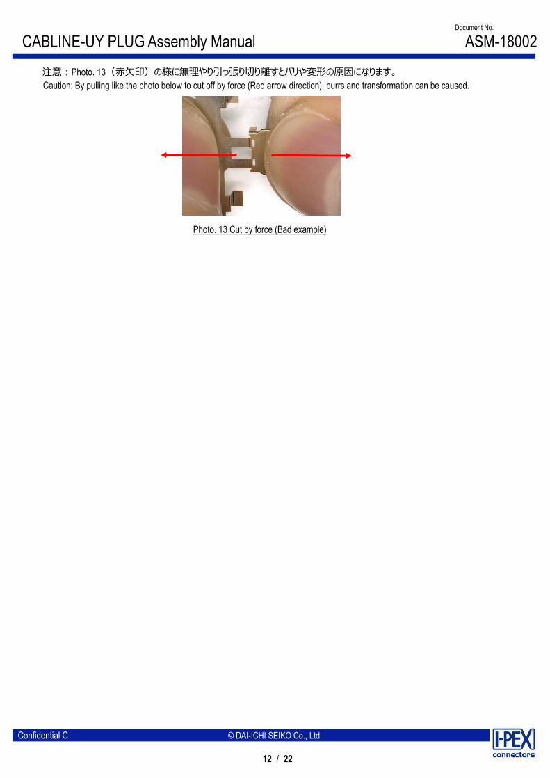
注意:Photo. 13(赤矢印)の様に無理やり引っ張り切り離すとバリや変形の原因になります。 Caution: By pulling like the photo below to cut off by force (Red arrow direction), burrs and transformation can be caused.
6-3. SHELL A 圧着手順 (SHELL A crimping procedure) ① photo15 の様に 6-1 で切り離した SHELL A を、圧着 JIG の受け JIG の上に背面側(Photo.12 参照)を下、 キャリアカット側を手前にしてセットする。 Set the SHELL A that cut it off in 6-1 on receive JIG of crimping Jig as shown in photo15. Back surface side (Refer to photo.12) shall be below and carrier cut side shall be front.
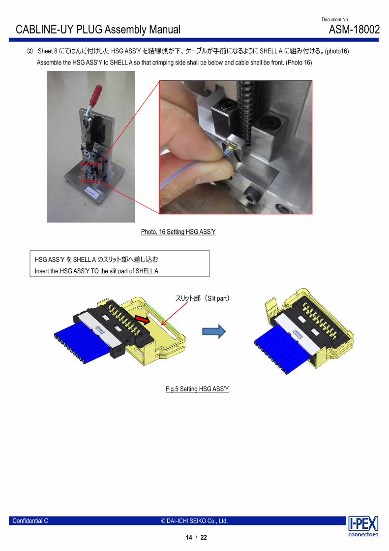
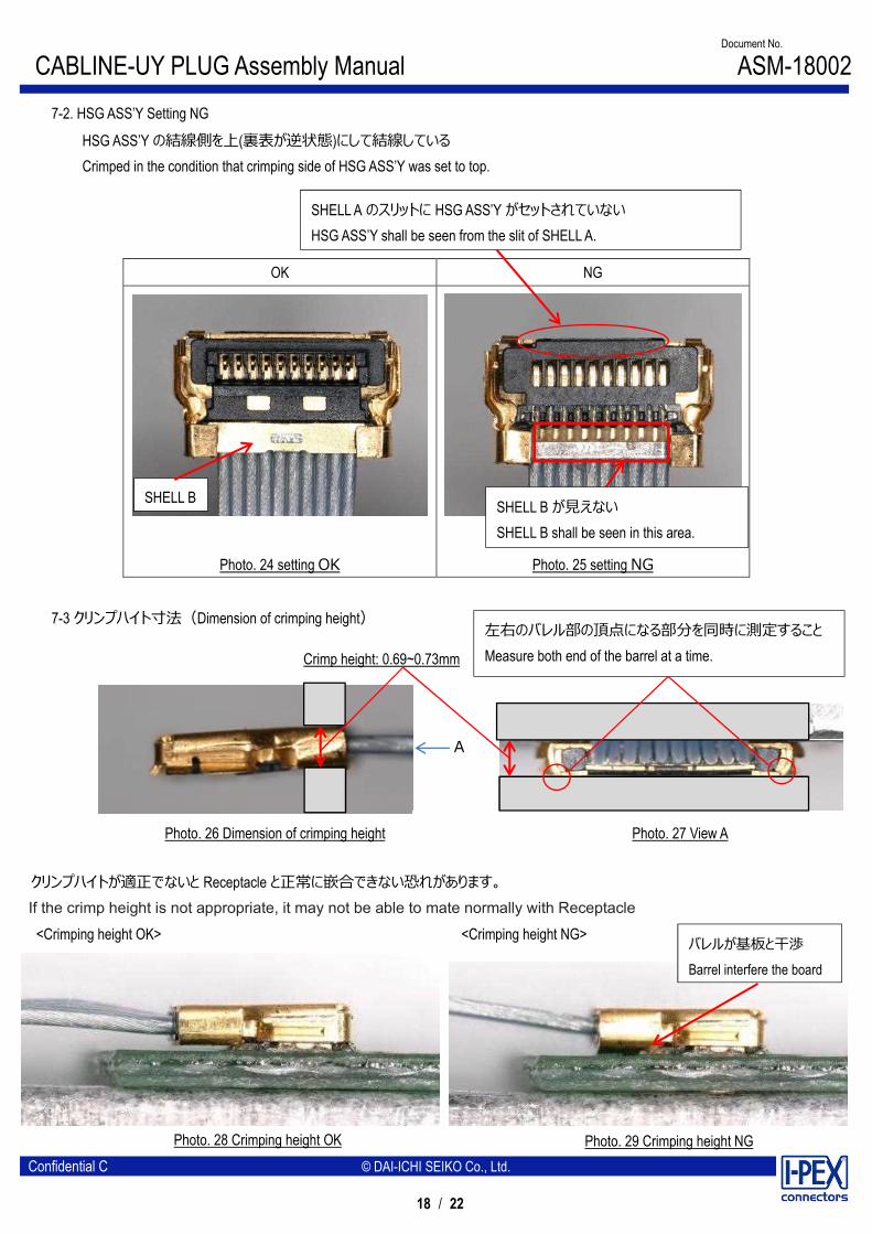
② Sheet 8 にてはんだ付けした HSG ASS’Y を結線側が下、ケーブルが手前になるように SHELL A に組み付ける。(photo16) Assemble the HSG ASS’Y to SHELL A so that crimping side shall be below and cable shall be front. (Photo 16)
Fig.5 Setting HSG ASS’Y
HSG ASS’Y を SHELL A のスリット部へ差し込む Insert the HSG ASS’Y TO the slit part of SHELL A.
●This Semi Auto machine is a jig for harnessing I-PEX CABLINE-UY(P/N:3568-0**1) to a specially processed coaxial cable. Therefore, non-specified connectors and cables are not allowed. Failure to do so may damage the jig.
●With the exception of the specified replacement area, loosen or removing bolts are prohibited. Modifying is prohibited to avoid the defect of the jig. Failure to do so may affect the quality of the product.
●For the jig maintenance, use brushes and air pressure regularly to remove cable chips and dusts on the jig. Apply sewing machine oil or the rust preventing oil (store-bought) to the sliding surfaces regularly.
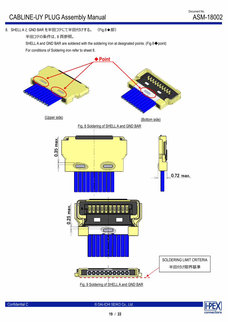
8. SHELL A と GND BAR を半田コテにて半田付けする。 (Fig.8◆部) 半田コテの条件は、8 頁参照。 SHELL A and GND BAR are soldered with the soldering iron at designated points. (Fig.8◆point)
For conditions of Soldering iron refer to sheet 8.
9. ケーブル固定(Cable fixation) ケーブル端末部を接着剤にて固定することを推奨する。 接着剤:LOCTITE 352 Fixing the cable terminal part with the bond is recommended.
Bond:LOCTITE 352
Fig.10 Bonding
●ボンディングは限界基準を超えないで下さい。 ●Bonding 塗布後、直ちに露光し凝固してください。放置すると接着剤がコネクタ内部に浸透し不具合の原因となります。 ●Bonding shall not exceed the limit criteria. ●Immediately after application of Bonding, expose and solidify.
If left unattended, the adhesive will penetrate into the connector and cause malfunctions.