52
Instructions for use CHAIRSIDE CAD all ceramic all you need

Instructions for usechairs ide
CAD
all ceramic
all you need

2
Table of Contents
3 IPS e.max System – one system for every indication
4 Product Information
Material
Usage
Composition
Scientific Data
CAD/CAM Partners
Block Concept
Preparation Guidelines
11 Overview of the Treatment Procedure
Overview of the treatment procedure
Shade Determination — Tooth Shade, Shade of the Preparation
Intraoral imaging
Milling
Preparation for Crystallization
Characterization / Glaze / Adjustments
Combination Firing
Preparing for Cementation
Cementation
18 Processing Possibilities IPS e.max CAD
19 Staining Technique
Veneers, Inlays, Onlays
– Preparation
– Finishing
– Combination Firing (Crystallization/Glaze firing)
– Completion of the Restoration
24 Partial Crowns, Crowns
– Preparation
– Finishing
– Preparing the Restoration for Combination Firing
– Combination Firing (Crystallization/Glaze firing)
– Option A: Crystallization and Stain/Glaze Firing in One Step with Glaze Spray
– Option B: Crystallization and Stain/Glaze Firing in One Step with Glaze Paste
– Completion of the Restoration
38 Cut-back Technique
40 Seating and Follow-Up Care
Possibilities for Cementation
Cementation
Recall
45 General Information
Frequently Asked Questions
Table on Block Selection
Crystallization and Firing Parameters
CAD
CAD
pr
od
uc
t
info
rm
at
ion
info
rm
a-
tio
n
pr
ac
tic
al
no
te
s o
n p
ro
ce
ss
ing

3
IPS e.max – one system for every indication
IPS e.max is an innovative all-ceramic system which covers the entire all-ceramic indication range – from
thin veneers to 12-unit bridges.
IPS e.max delivers high-strength and highly esthetic materials for the Press and the CAD/CAM
technologies. The system consists of innovative lithium disilicate glass-ceramics used mainly for sin-
gle-tooth restorations and high-strength zirconium oxide for large-span bridges.
Every patient situation presents its own requirements and objectives. IPS e.max meets these
requirements. Due to the system components you obtain exactly what you need.
– The components of the Press technology include the highly esthetic IPS e.max Press lithium disilicate
glass-ceramic ingots and the IPS e.max ZirPress fluorapatite glass-ceramic ingots for the fast and
efficient press-on-zirconia technique.
– Depending on the case requirements, two types of materials are available for CAD/CAM techniques:
the innovative IPS e.max CAD lithium disilicate blocks and the high-strength zirconium oxide IPS e.max
ZirCAD.
– The nano-fluorapatite layering ceramic IPS e.max Ceram, which is used to characterize/veneer all
IPS e.max components – glass or oxide ceramics – completes the IPS e.max system.
IPS e.max CAD
The shades and translucency levels of the IPS e.max CAD blocks are based on the overarching IPS e.max
shade system.
The IPS e.max CAD blocks are available in three different levels of opacity; the opaque MO blocks are for
labside use (layering technique). The more translucent LT and HT blocks are suitable for the chairside
fabrication of fully anatomical restorations (staining technique). The selection of the translucency level is
based on the clinical requirements (indication, shade of the prepared tooth, desired tooth shade)
presented by the patient.
e.max® System – all you need
IPS

4
e.max® CAD – Product Information
IPS
Material
IPS e.max CAD is a lithium disilicate glass-ceramic block for the
CAD/CAM technique. It is fabricated using an innovative process
which provides an impressive homogeneity of the material.
The block can be processed very easily in a CAD/CAM unit in its
pre-crystallized (“blue”) state. The typical and striking colour of the
pre-crystallized IPS e.max CAD blocks ranges from whitish to blue
and bluish-grey. The shade is a result of the composition and the
microstructure of the glass-ceramic. The strength of the material
is 130 to 150 MPa and thus comparable to other glass-ceramic
blocks currently available on the market. After the IPS e.max CAD
blocks are milled, the restoration is crystallized in an Ivoclar Vivadent
ceramic furnace (e.g. Programat® CS). Contrary to some other CAD/
CAM ceramics, the crystallization process does not lead to
significant shrinking and does not require time-consuming infiltra-
tion processes. Crystallization is completed after approx. 20 to
25 minutes. The crystallization at a temperature of 840°C (1544°F)
causes a transformation of the microstructure, during which lithium
disilicate crystals grow in a controlled manner. The densification of
0.2% is accounted for in the CAD software and taken into account
upon milling. The key physical parameters, such as the strength of
360 MPa and the corresponding optical properties, are achieved
through the transformation of the microstructure.
IPS e.max CAD blocks show a natural brightness. Due to the
translucency and shade variety, fully anatomical restorations can
easily be fabricated with this glass-ceramic.
CTE (100–500°C) [10-6/K] 10.5 ± 0.5
Flexural strength (biaxial) [MPa] ≥ 360 according to ISO 6872
Fracture toughness [MPa m0.5] ≥ 2.0 according to ISO 6872
Chem. solubility [µg/cm2] ≤ 50 according to ISO 6872
Classification: Ceramic Materials Type 2 / Class 3

5
Usage
Indications
– Veneers
– Inlays
– Onlays
– Partial crowns
– Crowns for anterior and posterior restorations
– Implant superstructures for single-tooth restorations (anterior and
posterior region)
Contraindications
– Full veneers on molar crowns
– Very deep subgingival preparations
– Patients with severely reduced residual dentition
– Parafunctions
– Any other use not listed in the indications
Important processing restrictions
Failure to observe the following restrictions may compromise the
results achieved with IPS e.max CAD:
– The frameworks must not fall below the required minimum
thickness.
– Do not mill the blocks with non-compatible CAD/CAM systems.
– Crystallization must not be conducted in a ceramic furnace that
has no vacuum function.
– Crystallization must not be conducted in a ceramic furnace that
has not been calibrated.
– Crystallization must not be conducted in a ceramic furnace that
has not been approved and/or recommended.
– Crystallization must not be conducted in a high-temperature
furnace (e.g. Programat S1).
– Do not mix IPS e.max CAD Crystall./Glaze, Shades and Stains with
other dental ceramics (e.g. IPS e.max Ceram Glaze, Stains and
Essence).
Side effects
If the patient is known to be allergic to any of the components
of IPS e.max CAD, the material must not be used to fabricate
restorations.
Composition
– IPS e.max CAD Blocks
Components: SiO2
Additional contents: Li2O, K2O, MgO, Al2O3, P2O5 and other
oxides
– IPS e.max CAD Crystall./Glaze, Shades and Stains
Components: oxides, glycols
– IPS e.max CAD Crystall./Glaze Spray
Components: oxides, propanol, propellant: isobutane
– IPS e.max CAD Crystall./Glaze Liquid
Components: butandiol
– IPS e.max CAD Crystall./Add-On
Components: oxides
– IPS e.max CAD Crystall./Add-On Liquid
Components: water, propylene glycol, butandiol and chloride
– IPS Object Fix Putty/Flow
Components: oxides, water, thickening agent
– IPS Contrast Spray Chairside (blue-lemon, cream-lemon)
Components: pigment suspension in ethanol, propellant:
fluorinate hydrocarbon
– IPS Ceramic Etching Gel
Components: hydrofluoric acid (approx. 5%)
Warning
– Do not inhale ceramic dust during finishing — use exhaust air
discharge and mouth protection.
– IPS Ceramic Etching Gel contains hydrofluoric acid. Contact
with skin, eyes and clothing must be prevented at all costs,
since the material is extremely toxic and corrosive. The etching
gel is intended for extraoral use only and must not be applied
intra-orally (inside the mouth).
6
Scientific Data
Further scientific data (i.e. strength, wear, biocompatibility) are contained in the “Scientific
Documentation IPS e.max CAD”. The Documentation also provides a set of studies that describe the
clinical performance of IPS e.max CAD.
This Scientific Documentation can be obtained from Ivoclar Vivadent.
For further information about all-ceramics and IPS e.max in general, please refer to the Ivoclar Vivadent
Reports No. 16 and No. 17.
Scientific Documentation

7
CAD/CAM partners
IPS e.max CAD has to be processed with an authorized CAD/CAM system. For questions regarding the
different systems, please contact the respective cooperation partners.
More information is available on the Internet from www.ivoclarvivadent.com.

8
Block Concept
IPS e.max CAD is available in the A-D and Bleach BL shades as well as in three levels of translucency
(HT, LT, MO) and two sizes (I 12, C 14). From a processing point of view, basically all restorations can
be fabricated from any block. Both the IPS e.max CAD HT and IPS e.max CAD LT blocks are used for
chairside applications (staining technique).
For reasons of esthetics, however, the following processing techniques and indications are recommend-
ed for the individual blocks (translucency levels):
IPS e.max CAD HT (High Translucency)
The HT Blocks are available in 16 A-D and 4 Bleach BL shades and 2 sizes (I 12, C 14). Given their
high translucency, HT blocks are ideally suitable for the fabrication of smaller restorations (e.g. inlays and
onlays). Restorations made of HT blocks convince users with their true-to-nature chameleon effect and
the exceptional adaption to the remaining tooth structure.
IPS e.max CAD LT (Low Translucency)
The LT Blocks are available in 16 A-D and 4 Bleach BL shades and 2 sizes (I 12, C 14). Due to their
high brightness values compared to the HT blocks, LT blocks are ideally suitable for the fabrication of
larger restorations (e.g. anterior and posterior crowns). Restorations made of LT blocks convince users
with their lifelike brightness value and chroma. This prevents the incorporated restorations from graying.
The cut-back technique can also be ideally used for restorations made from LT blocks.
The entire IPS e.max delivery program can be found at www.ivoclarvivadent.com!
Indications
Medium
Opacity
Low
Translucency
High
Translucency
CR %
Staining Technique
Cut-Back Technique
Layering Technique1)
Inlays Onlays Veneers Partial Crowns
Anterior Crowns
Posterior Crowns
Translucency level
Processing Technique
✓ ✓
✓ ✓ ✓ ✓ ✓
✓
✓
1)labside application * up to the second premolar
✓
✓
✓*

9
Preparation Guidelines
Successful results can only be achieved with IPS e.max CAD if the guidelines and framework thicknesses are strictly
observed.
Basic preparation guidelines for all-ceramic restorations
– no angles or sharp edges
– shoulder preparation with rounded inner edges and/or chamfer preparation
– the indicated dimensions reflect the minimum thickness for IPS e.max CAD restorations
– the incisal edge of the preparation, particularly for anterior teeth, should be at least 1.0 mm (milling tool geometry) in
order to permit optimum milling during CAD/CAM processing.
0.6
0.6
0.7
0.6
0.6
0.7
1.0
1.5
1.0
1.0
1.5
1.2 1.2 1.0
1.5
1.0
1.5
1.5
1.5
1.5 1.5
1.0 1.0
1.5
1.5
1.5
6°
0.6
0.6
0.7
1.0
1.0
6° 6°
1.01.0
100-120°
1.0
1.0
1.5
1.2 1.2 1.0
1.5
1.0
1.5
1.5
1.5
1.5 1.5
1.0 1.0
1.5
1.5
1.5
6°
0.6
0.6
0.7
1.0
1.0
6° 6°
1.01.0
100-120°
– If possible, the preparation should be located in the
enamel.
– The incisal preparation margins should not be located
in the area of static or dynamic enamel contact.
– Reduction in the cervical and/or labial area by 0.6 mm,
and the incisal edge by 0.7 mm.
– Reduce the anatomical shape and observe the
stipulated minimum thickness. Prepare a shoulder with
rounded inner edges or a deep chamfer. Width of the
shoulder/chamfer at least 1.0 mm.
– Reduce the incisal edge by approx. 1.5 mm.
– Reduce the labial or lingual area by approx. 1.2 mm.
– For conventional and/or self-adhesive cementation,
the preparation must demonstrate retentive surfaces.
Veneers Anterior crown

10
1.0
1.0
1.5
1.2 1.2 1.0
1.5
1.0
1.5
1.5
1.5
1.5 1.5
1.0 1.0
1.5
1.5
1.5
6°
0.6
0.6
0.7
1.0
1.0
6° 6°
1.01.0
100-120°
1.0
1.0
1.5
1.2 1.2 1.0
1.5
1.0
1.5
1.5
1.5
1.5 1.5
1.0 1.0
1.5
1.5
1.5
6°
0.6
0.6
0.7
1.0
1.0
6° 6°
1.01.0
100-120°
– Static and dynamic antagonist contacts must be taken
into consideration.
– The preparation margins must not be located on
centric antagonist contacts.
– Provide at least 1.5 mm of reduction in the cusp
areas.
– Prepare a circular shoulder with rounded inner edges
or a deep chamfer. Width of the shoulder/chamfer
should be at least 1.0 mm.
– Reduce the anatomical shape and observe the
stipulated minimum thickness. Prepare a circular
shoulder with rounded inner edges or a deep chamfer.
Width of the shoulder/chamfer at least 1.0 mm.
– Reduce the incisal crown third by approx. 1.5 mm.
– Reduce the buccal or lingual area by approx. 1.5 mm.
– For conventional and/or self-adhesive cementation, the
preparation must demonstrate retentive surfaces.
Partial crown Posterior crown
1.0
1.0
1.5
1.2 1.2 1.0
1.5
1.0
1.5
1.5
1.5
1.5 1.5
1.0 1.0
1.5
1.5
1.5
6°
0.6
0.6
0.7
1.0
1.0
6° 6°
1.01.0
100-120°
1.0
1.0
1.5
1.2 1.2 1.0
1.5
1.0
1.5
1.5
1.5
1.5 1.5
1.0 1.0
1.5
1.5
1.5
6°
0.6
0.6
0.7
1.0
1.0
6° 6°
1.01.0
100-120°
1.0
1.0
1.5
1.2 1.2 1.0
1.5
1.0
1.5
1.5
1.5
1.5 1.5
1.0 1.0
1.5
1.5
1.5
6°
0.6
0.6
0.7
1.0
1.0
6° 6°
1.01.0
100-120°
– Static and dynamic antagonist contacts must be taken
into consideration.
– The preparation margins must not be located on
centric antagonist contacts.
– A preparation depth of at least 1.0 mm and an
isthmus width of at least 1.0 mm must be observed in
the fissure area.
– Prepare the proximal box with slightly diverging walls
and observe an angle of 100°-120° between the
proximal cavity walls and the prospective proximal
inlay surfaces.
For inlays with pronounced convex cavity walls with-
out adequate support by the proximal shoulder,
marginal ridge contacts should be avoided.
– Round out internal edges in order to prevent stress
concentration within the ceramic material.
– Do not prepare slice-cuts/bevels or feather edges.
– Static and dynamic antagonist contacts must be taken
into consideration.
– The preparation margins must not be located on
centric antagonist contacts.
– A preparation depth of at least 1.0 mm and an isthmus
width of at least 1.0 mm must be observed in the
fissure area.
– Prepare the proximal box with slightly diverging walls
and observe an angle of 100°-120° between the
proximal cavity walls and the prospective proximal
onlay surfaces.
For onlays with pronounced convex cavity walls with-
out adequate support by the proximal shoulder,
marginal ridge contacts should be avoided.
– Round out internal edges in order to prevent stress
concentration within the ceramic material.
– Do not prepare slice-cuts/bevels or feather edges.
– Provide at least 1.0 mm of reduction in the cusp areas.
Inlay Onlay

11
e.max® CAD Overview of the Treatment Procedure
IPS
Ove
rvie
w o
f th
e Tr
eatm
ent
Pro
ced
ure
IPS e.max CAD Crystallization Tray / PinsSpecial firing tray and pins for the crystallization of IPS e.max CAD IPS® Object Fix Putty / Flow Auxiliary firing paste in different viscosities for the crystal-lization of IPS e.max CAD.
IPS e.max CAD Crystall./Shades, Stains, Glaze and Glaze Liquid Special stains in paste form for the individual surface characterization of IPS e.max CAD in the “blue” state. IPS e.max CAD Crystall./Glaze Spray Special glaze in spray form for IPS e.max CAD IPS e.max CAD Crystall./ Add-On und Add-On Liquid Special add-on material for IPS e.max CAD
IPS e.max CAD Blocks Lithium disilicate glass-ceramic blocks for the CAD/CAM technology.
Milling
Preparing for Crystallization
Characterization / Glaze / Adjustments
OptraGate®
Provides easy access to an enlarged treatment area by circular retraction of lips and cheeks.
IPS® Contrast Spray Chairside (blue-lemon, creme-lemon)Enables optimum imaging through detailed definition of the margins
Virtual® CADbite Registration Scannable bite registration material, e.g. to record data used for optical imaging.
Cementation
IPS® Ceramic Etching Gel For the fabrication of retentive bonding surfaces on all-ceramic restorations. Monobond® Plus
Produces silanated bonding surfaces on etched all- ceramic restorations.
Preparation for Cementation
Intraoral imaging
Combination firing (Crystallization/Glaze)
Programat® CS2 Compact, easy-to-operate ceramic furnace with vacuum function for the dental practice.
Variolink® Veneer, Variolink® II, Multilink® AutomixTried-and-tested adhesive cementation system. SpeedCEM® Self-adhesive, self-curing resin cement with light-curing option for quick and easy cementation. Vivaglass® CEM Esthetic glass-ionomer cement for the conventional cementation. Bluephase® Cordless high-performance LED light for all indications.
Working Steps Ivoclar Vivadent-Produkte
Shade Determination
Tooth shade IPS e.max Press/CAD HT and LT determination materials shade guide For optimum selection of the
block shade.
Die shade IPS® Natural Die Material determination To determine the shade of the prepared tooth.

12
Shade Determination — Tooth Shade, Shade of the Prepared Tooth
Optimum integration in the oral cavity of the patient is the prequisite for a true-to-nature all-ceramic
restoration. To achieve this, the following guidelines and notes must be observed by the dentist.
The overall esthetic result of an all-ceramic restoration is influenced by the following factors:
• Shade of the preparation (natural preparation, core build-up, abutment, implant)
• Shade of the restoration (framework shade, veneer, characterization)
• Shade of the cementation material
The optical effect of the preparation shade must not be underestimated during the fabrication of highly
esthetic restorations. For that reason, the shade of the preparation should be determined together with
the desired tooth shade in order to select the suitable block. Especially with severely discoloured
preparations or non-tooth-shaded build-ups, this is of utmost importance. In order to achieve the
desired esthetics, the shade of the prepared tooth must first be determined.
Preparation shade
– Prepared natural tooth– Core build-up– Implant, abutment
Cementation Material
Desired Tooth Shade
Restoration Shade
– Framework– Veneer– Characterization

13
Shade determination of the natural tooth
After tooth cleaning, the tooth shade of the non-prepared tooth and/or the adjacent teeth is deter-
mined with the help of a shade guide. Individual characteristics have to be considered when determin-
ing the tooth shade. If a crown preparation is planned, for example, the cervical shade should also be
determined. In order to achieve the best possible true-to-nature results, shade determination should be
carried out in daylight. Furthermore, the patient should not wear clothes of intense colours and/or lip-
stick.
Die shade selection
In order to facilitate the reproduction of the desired tooth shade, the shade of the preparation is
determined with the help of the IPS Natural Die Material shade guide. This allows the clinician to select
the appropriate IPS e.max CAD blocks in terms of shade and translucency
based on the indication.
Please refer to the table on page 49 for block selection.
Which block should be used?
The suitable block is selected on the basis of the following criteria:
1. Desired tooth shade
2. Preparation shade or abutment shade
3. Type of restoration
4. Restoration thickness and/or preparation depth
5. Processing technique (staining and cut-back technique)
6. Cementation material
Please refer to the table on page 49 for block selection.
Ove
rvie
w o
f th
e Tr
eatm
ent
Pro
ced
ure
Example of the preparation shade effect
Crown made of IPS e.max CAD HT B1 on different preparation shades.

14 14
Intraoral Imaging
To prepare for the optical imaging, OptraGate® is placed to facilitate access to the
treatment field. OptraGate is a clinical auxiliary device that retracts lips and cheeks
during dental treatment. It enables a full view of the treatment field, facilitates the
accessibility, and improves the moisture control in the oral cavity.
Milling
In order to mill the restoration, the appropriate IPS e.max CAD block is selected in
accordance with the clinical situation. It not only determines the selection of the block
in the required shade, but also the block size to be offered. Once the desired block
has been selected, it is mounted in the CAM unit and the restoration is milled.
IPS® Contrast Spray Chairside is used to prepare the intraoral situation
for optical imaging. The IPS Contrast Spray Chairside balances out the
different optical properties of the natural tooth (dentin and enamel) and
thus permits optimum recording using the camera. The optimized geo-
metry of the rotatable single-use nozzle provides good accessibility to the
preparation. The IPS Contrast Spray is available in the colours blue and
cream; both versions feature a fresh lemon flavour.
Virtual® CADbite is a scannable bite registration material
with a reflecting surface, which is ideally suitable for capturing
images with intraoral scanning devices (antagonist
data).

1515
Preparing for Crystallization
IPS Object Fix Putty and IPS Object Fix Flow are auxiliary firing pastes with
different viscosities to support IPS e.max CAD restorations during the crystallization
process. The pastes are used to stabilize and secure the corresponding restoration on
the IPS e.max CAD Crystallization Pins.
IPS Object Fix Putty and IPS Object Fix Flow are easy to apply
and remove after the firing procedure.
Characterization / Glaze / Adjustments
IPS e.max CAD restorations are characterized with
IPS e.max CAD Crystall./Shades and Stains. There are
7 IPS e.max CAD Crystall./Stains and 5 IPS e.max CAD
Crystall./Shades available. To imitate the incisal area,
2 IPS e.max CAD Crystall./Shade Incisal materials,
which enhance the optical in-depth effect and the translucency in the incisal
third, can be used.
IPS e.max CAD Crystall./Glaze Liquid is used to dilute the IPS e.max CAD Crystall./
Shades, Stains and Glaze pastes.
To glaze the IPS e.max CAD restoration, you may choose between the
IPS e.max CAD Crystall./Glaze Paste and the IPS e.max CAD Crystall./
Glaze Spray.
For shape adjustments (e.g. proximal or occlusal contact points), IPS e.max CAD
Crystall./Add-On is available . It is mixed with the IPS e.max CAD Crystall./
Add-On Liquid and can be directly applied with the crystallization firing or any
subsequent corrective firing.
Ove
rvie
w o
f th
e Tr
eatm
ent
Pro
ced
ure

16
Combination Firing (Crystallization/Glaze)
As a general rule, IPS e.max CAD is fired on the IPS e.max CAD Crystallization Tray
and the corresponding IPS e.max CAD Crystallization Pins. This firing tray
stores heat and ensures slow cooling of the glass-ceramic.
The firing cycles are conducted in a Programat® CS/CS2 or any other ceramic furnace
from Ivoclar Vivadent.
The Programat CS/CS2 is easy to operate and especially suitable for glaze and
crystallization firings. Also because of the integrated vacuum function, this furnace is
ideally suitable for processing IPS e.max CAD blocks.
Preparing for Cementation
Conditioning of the ceramic surface to prepare for cementation is decisive for
generating a sound bond between the cementation material and the all-ceramic resto-
ration. Generally, glass-ceramics are etched with IPS Ceramic Etching Gel
(5% hydrofluoric acid). IPS e.max CAD is etched for 20 seconds.
Etching produces retentive bonding surfaces, which increases the bond
between luting composite and the all-ceramic restoration.
IPS Ceramic Etching Gel is for extraoral use only and must not be
applied in the oral cavity.
Subsequent silanization of the bonding surface with Monobond® Plus generates a
sound bond between the etched all-ceramic material and the luting composite.
The bonding silane thus plays an important role for the overall bonding strength
between the IPS e.max CAD restoration and the tooth structure.
Total Etch
Total Etch is used to prepare the tooth for the adhesive cementation using Variolink.
Total Etch is a gel used to etch the enamel and condition the dentin in situations
where all-ceramic restorations are to be cemented adhesively.

17
Cementation
For the cementation of IPS e.max CAD restorations, you may choose between conventional, self-adhesive or the adhe-
sive cementation technique, according to the indication. For this purpose, you may choose between the tried-and-tested
cementation materials from the coordinated assortment of Ivoclar Vivadent.
Variolink® II / Variolink Veneer
The dual-curing, highly esthetic luting composite Variolink II has been successfully used for more
than 10 years and offers excellent clinical results. The new light-curing Variolink Veneer is
especially indicated for the adhesive cementation of veneers. This material allows the
user to increase or decrease the brightness of the ceramic restoration due to a special
shade concept.
Multilink® Automix Easy Clean-Up
This universal dual-curing luting composite offers a wide range of indications and high bond
strengths to IPS e.max CAD.
SpeedCEM
SpeedCEM is a dual-curing, self-adhesive resin cement for the quick and easy
cementation of high-strength all-ceramic, metal and metal-ceramic restorations.
SpeedCEM eliminates the need for conditioning of enamel or dentin with phosphoric
acid and bonding.
LED lights of the Bluephase® family are used for the polymerization of
light-curing and dual-curing adhesive composites.
The high light intensity achieved with the Bluephase curing light permits comparatively
short polymerization times with simultaneous good polymerization depth.
✓Veneers
IPS e.max CAD
–– ––
✓Inlays, onlays, partial crowns –– ––
✓Anterior crowns ✓ ✓
✓Posterior crowns ✓ ✓
Adhesive cementation
Self-adhesive cementation
Conventional cementation
Cementation methods in relation to the indication
Ove
rvie
w o
f th
e Tr
eatm
ent
Pro
ced
ure

18
e.max® CAD Processing Options
IPS
Preparation
CAD/CAM Process
Clinical try-in
Recommended option
Veneer, inlay, onlay
using glaze paste
See page 21
– Veneer, inlay, onlay on OptraStick
– Aplication of the glaze paste and stains using
a brush
– Combination firing (Crystallization/Glaze);
duration: approx. 25 minutes
Veneer, inlay, onlay
using glaze spray
See page 30
– Veneer, inlay, onlay must be secured with
IPS Object Fix Putty on a pin. Adapt Object
Fix Putty exactly to the margins (see page 27).
– Application of stains using a brush
– Application of the Glaze Spray
– Speed-crystallization/Glaze Spray (at most
2 restorations at a time),
duration: approx. 20 minutes
Recommended option
Partial crown, crown
using glaze spray
See page 24
– Attach the partial crown, crown to the pin
using IPS Object Fix Putty or Flow
– Apply the stains using a brush
– Application of the Glaze Spray
– Speed-crystallization/Glaze Spray
(at most 2 restorations at a time),
duration: approx. 20 minutes
Partial crown, crown
using glaze paste
See page 34
– Attach the partial crown, crown to the pin
using IPS Object Fix Putty or Flow
– Aplication of the glaze paste and stains using
a brush
– Combination firing (Crystallization/Glaze);
duration: approx. 25 minutes
After clinical try-in, the restoration is finished, depending on the type of restoration. There are various options available for
finishing.

19
IPS e.max CAD HT blocks are particularly suitable for the fabrication of veneers, inlays and onlays. Please note that, due to
the high translucency of the HT blocks, the prepared tooth must show no or only slight discolouration.
Individualized characterizations and glaze are applied before the combined Crystallization and Glaze firing is conducted.
Because of the combined firing, processing is very efficient and leads to a highly esthetic result quickly and easily.
Preparation
After the determination of the tooth shade, preparation is carried out according to the preparation guidelines. As a
preparation for intra-oral imaging, the cleaned and dried preparation is covered with IPS Contrast Spray Chairside
(blue-lemon or cream-lemon) with one short spray discharge.
e.max® CAD Processing Options
Initial situation: Restoration of tooth 26 is to be replaced. Preparation: occlusal view
Preparation sprayed with IPS Contrast Spray Chairside cream-lemon ready for intra-oral recording
For information on the CAD/CAM processing, please refer to the respective Instructions for Use and the
manuals of the respective CAD/CAM system. The instructions of the manufacturers must be followed.
The suitable IPS e.max CAD Block is selected on the basis of the desired tooth shade
and the determined shade of the prepared tooth.
Please refer to the table on page 49 for block selection.
Stai
nin
g T
ech
niq
ue
IPS e.max® CAD
Staining Technique – Veneers, Inlays, Onlays

20
Finishing
It is of critical importance to use the correct grinding instruments for finishing and adjusting IPS e.max CAD. If unsuitable
grinding instruments are used, chipping of the edges and local overheating may occur (please observe the Ivoclar Vivadent
Flow Chart “Recommended grinding tools for IPS e.max glass-ceramics”).
Observe the following procedure for finishing IPS e.max CAD restorations:
– Carry out adjustments by grinding of IPS e.max CAD restorations while they are still in their pre-crystallized (blue) state, if
possible.
– Only use suitable grinding instruments, low rpms and light pressure to prevent delamination and chipping at the edges
in particular.
– Adjustments by grinding are carried out with fine-grained diamonds (<60 µm) and/or medium-fine diamond polishers
– Overheating of the glass-ceramic must be avoided.
– Smooth out the attachment point of the holder and take proximal contact points into account.
– If necessary, carry out individual shape adjustments.
– Carefully try-in the restoration in its blue state and adjust the occlusion/articulation.
– Design surface textures.
– Always clean the restoration with ultrasound in a water bath or blast with the steam jet before crystallization. Make sure
to thoroughly clean the restoration before further processing and to remove any residue of the milling additive of the
CAD/CAM milling unit. Residue of the milling additive remaining on the surface may result in bonding problems and
discolouration during the Crystallization/Glaze firing.
– Do not blast the restorations with Al2O3 or glass polishing beads.
Finish restoration margins with medium-fine diamond polishers.Smooth out the attachment point and take proximal contacts into account.
Careful try-in of the IPS e.max CAD HT onlay in its pre-crystallized (“blue”) state. Check the fit as well as the proximal and occlusal contact points.
Adjusting the outer surface, particularly functional areas of the restoration with a fine dia-mond to smooth out the surface structure created by the CAD/CAM process.
Finish functional areas (occlusal contact surfaces) of the restoration with fine diamonds in order to smooth
out the surface structure created by CAD/CAM processing.
21
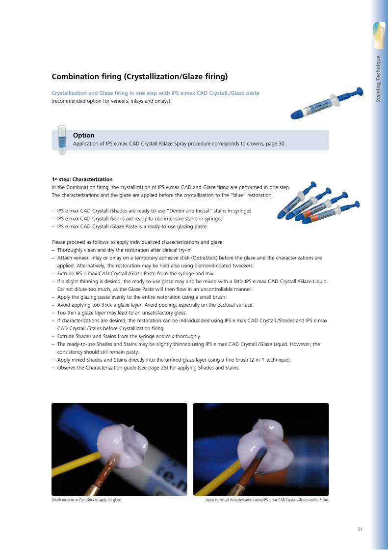
Combination firing (Crystallization/Glaze firing)
Crystallization and Glaze firing in one step with IPS e.max CAD Crystall./Glaze paste
(recommended option for veneers, inlays and onlays)
1st step: Characterization
In the Combination firing, the crystallization of IPS e.max CAD and Glaze firing are performed in one step.
The characterizations and the glaze are applied before the crystallization to the “blue” restoration.
– IPS e.max CAD Crystall./Shades are ready-to-use “Dentin and Incisal” stains in syringes
– IPS e.max CAD Crystall./Stains are ready-to-use intensive stains in syringes
– IPS e.max CAD Crystall./Glaze Paste is a ready-to-use glazing paste
Please proceed as follows to apply individualized characterizations and glaze:
– Thoroughly clean and dry the restoration after clinical try-in.
– Attach veneer, inlay or onlay on a temporary adhesive stick (OptraStick) before the glaze and the characterizations are
applied. Alternatively, the restoration may be held also using diamond-coated tweezers.
– Extrude IPS e.max CAD Crystall./Glaze Paste from the syringe and mix.
– If a slight thinning is desired, the ready-to-use glaze may also be mixed with a little IPS e.max CAD Crystall./Glaze Liquid.
Do not dilute too much, as the Glaze Paste will then flow in an uncontrollable manner.
– Apply the glazing paste evenly to the entire restoration using a small brush.
– Avoid applying too thick a glaze layer. Avoid pooling, especially on the occlusal surface.
– Too thin a glaze layer may lead to an unsatisfactory gloss.
– If characterizations are desired, the restoration can be individualized using IPS e.max CAD Crystall./Shades and IPS e.max
CAD Crystall./Stains before Crystallization firing.
– Extrude Shades and Stains from the syringe and mix thoroughly.
– The ready-to-use Shades and Stains may be slightly thinned using IPS e.max CAD Crystall./Glaze Liquid. However, the
consistency should still remain pasty.
– Apply mixed Shades and Stains directly into the unfired glaze layer using a fine brush (2-in-1 technique).
– Observe the Characterization guide (see page 28) for applying Shades and Stains.
Apply individual characterizations using IPS e.max CAD Crystall./Shades and/or Stains.Attach onlay to an OptraStick to apply the glaze.
OptionApplication of IPS e.max CAD Crystall./Glaze Spray procedure corresponds to crowns, page 30.
Stai
nin
g T
ech
niq
ue
22
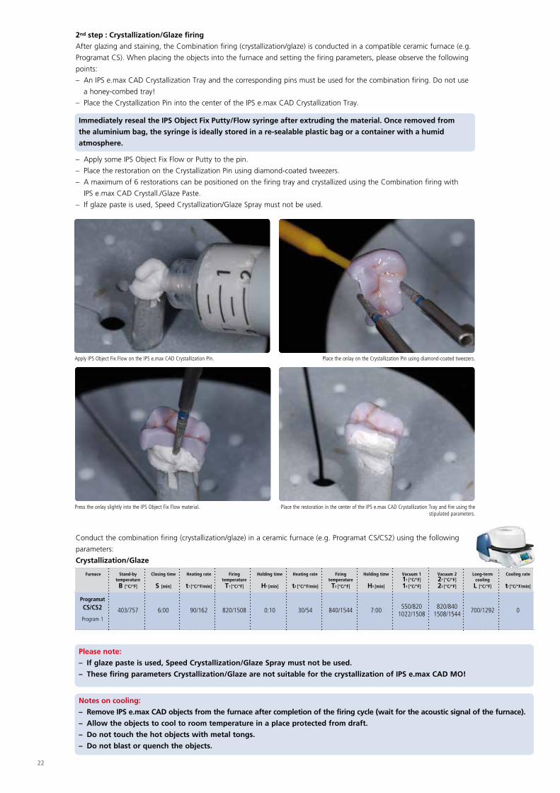
Place the restoration in the center of the IPS e.max CAD Crystallization Tray and fire using the stipulated parameters.
Press the onlay slightly into the IPS Object Fix Flow material.
Place the onlay on the Crystallization Pin using diamond-coated tweezers.Apply IPS Object Fix Flow on the IPS e.max CAD Crystallization Pin.
2nd step : Crystallization/Glaze firing
After glazing and staining, the Combination firing (crystallization/glaze) is conducted in a compatible ceramic furnace (e.g.
Programat CS). When placing the objects into the furnace and setting the firing parameters, please observe the following
points:
– An IPS e.max CAD Crystallization Tray and the corresponding pins must be used for the combination firing. Do not use
a honey-combed tray!
– Place the Crystallization Pin into the center of the IPS e.max CAD Crystallization Tray.
– Apply some IPS Object Fix Flow or Putty to the pin.
– Place the restoration on the Crystallization Pin using diamond-coated tweezers.
– A maximum of 6 restorations can be positioned on the firing tray and crystallized using the Combination firing with
IPS e.max CAD Crystall./Glaze Paste.
– If glaze paste is used, Speed Crystallization/Glaze Spray must not be used.
Immediately reseal the IPS Object Fix Putty/Flow syringe after extruding the material. Once removed from
the aluminium bag, the syringe is ideally stored in a re-sealable plastic bag or a container with a humid
atmosphere.
Conduct the combination firing (crystallization/glaze) in a ceramic furnace (e.g. Programat CS/CS2) using the following
parameters:
Crystallization/Glaze
Furnace
Programat
CS/CS2
Program 1
Stand-by temperature B [°C/°F]
403/757
Closing time
S [min]
6:00
Heating rate
t1 [°C/°F/min]
90/162
Firing temperature T1 [°C/°F]
820/1508
Holding time
H1 [min]
0:10
Heating rate
t2 [°C/°F/min]
30/54
Firing temperature T2 [°C/°F]
840/1544
Holding time
H2 [min]
7:00
Vacuum 111 [°C/°F]12 [°C/°F]
550/8201022/1508
Vacuum 221 [°C/°F]22 [°C/°F]
820/840
1508/1544
Long-term cooling L [°C/°F]
700/1292
Cooling rate
tl [°C/°F/min]
0
Please note:
– If glaze paste is used, Speed Crystallization/Glaze Spray must not be used.
– These firing parameters Crystallization/Glaze are not suitable for the crystallization of IPS e.max CAD MO!
Notes on cooling:
– Remove IPS e.max CAD objects from the furnace after completion of the firing cycle (wait for the acoustic signal of the furnace).
– Allow the objects to cool to room temperature in a place protected from draft.
– Do not touch the hot objects with metal tongs.
– Do not blast or quench the objects.

23
Final try-in of the restoration before cementation ... or with steam.
Remove residue with ultrasound in a water bath …Remove the cool restoration from the hardened IPS Object Fix Putty or Flow.
If additional characterizations or adjustments are required after crystallization, a corrective firing using
IPS e.max CAD Crystall./Shades and Stains and Glaze can be conducted. Conduct the corrective firing also on the
IPS e.max CAD Crystallization Tray.
For minor shape adjustments (e.g. proximal or occlusal contact points), IPS e.max CAD Crystall./Add-On is available.
The adjustments may be made with both Crystallization/Glaze and Corrective firing. The detailed procedure is
described on page 36.
Furnace
Programat
CS/CS2
Program 2
Stand-by temperatureB [°C/°F]
403/757
Closing time
S [min]
6:00
Heating rate
t1 [°C/°F/min]
90/162
Firing temperature T1 [°C/°F]
820/1508
Holding time
H1 [min]
0:10
Heating rate
t2 [°C/°F/min]
30/54
Firing temperature T2 [°C/°F]
840/1544
Holding time
H2 [min]
3:00
Vacuum 111 [°C/°F] 12 [°C/°F]
550/8201022/1508
Vacuum 221 [°C/°F] 22 [°C/°F]
820/840
1508/1544
Long-term cooling L [°C/°F]
700/1292
Cooling rate
tl [°C/°F/min]
0
Correction firing
Completion of the Restoration
Once the IPS e.max CAD restoration has cooled to room temperature, proceed with the following steps:
– Remove the restoration from the hardened auxiliary firing paste.
– Remove any residue with ultrasound in a water bath and/or with steam.
– Do not blast residues using Al2O3 or glass polishing beads.
– Final try-in of the restoration before cementation.
– If adjustments by grinding are required, make sure that no overheating of the glass-ceramic occurs.
– Use fine-grained diamonds (< 60 µm) for finishing, followed by rubber polishers at low speed and limited pressure. For
the selection of the appropriate grinding tools, refer to the Ivoclar Vivadent Flow Chart “Recommended grinding tools –
chairside”.
– Finally, polish the adjusted areas to a high gloss (e.g. using OptraFine).
– Thoroughly clean the restoration.
Stai
nin
g T
ech
niq
ue

24
IPS e.max CAD LT blocks are ideally suitable for the fabrication of larger restorations (partial crowns, crowns) on prepared
teeth that are not or only slightly discoloured. Due to the higher brightness compared with IPS e.max CAD HT, a
“greying“ of the restoration is prevented.
Individualized characterizations and glaze are applied before the combined Crystallization and Glaze firing is conducted.
Because of the combined firing, processing is very efficient and leads to a highly esthetic result quickly and easily.
Preparation
After the determination of the tooth shade, preparation is carried out according to the preparation guidelines. As a
preparation for intra-oral imaging, the cleaned and dried preparation is covered with IPS Contrast Spray Chairside
(blue-lemon or cream-lemon) with one short spray discharge.
e.max® CAD Staining Technique – Partial Crowns, Crowns
IPS
Initial situation: The crown on tooth 37 has to be replaced Preparation: occlusal view
Preparation: buccal Preparation sprayed with IPS Contrast Spray Chairside cream-lemon; ready for intraoral recording
For information on the CAD/CAM processing, please refer to the respective Instructions for Use and the
manuals of the respective CAD/CAM system. The instructions of the manufacturers must be followed.
The suitable IPS e.max CAD Block is selected on the basis of the desired tooth shade
and the determined shade of the prepared tooth.
Please refer to the table on page 49 for block selection.

25
Finishing
It is of critical importance to use the correct grinding instruments for finishing and adjusting IPS e.max CAD. If unsuitable
grinding instruments are used, chipping of the edges and local overheating may occur (please observe the Ivoclar Vivadent
Flow Chart “Recommended grinding tools for IPS e.max glass-ceramics”).
Observe the following procedure for finishing IPS e.max CAD restorations:
– Carry out adjustments by grinding of IPS e.max CAD restorations while they are still in their pre-crystallized (blue) state, if
possible.
– Only use suitable grinding instruments, low rpms and light pressure to prevent delamination and chipping at the edges
in particular.
– Adjustments by grinding are carried out with fine-grained diamonds (< 60 µm) and/or medium-fine diamond polishers.
– Overheating of the glass-ceramic must be avoided.
– Smooth out the attachment point of the holder and take proximal contact points into account.
– Carry out individual shape adjustments, if required.
– Careful try-in of the restoration in its blue state and adjust the occlusion/articulation.
– Design surface textures.
– Always clean the restoration with ultrasound in a water bath or blast with the steam jet before crystallization. Make sure
to thoroughly clean the restoration before further processing and to remove any residue of the milling additive of the
CAD/CAM milling unit. Residue of the milling additive remaining on the surface may result in bonding problems and
discolouration during the Crystallization/Glaze firing.
– Do not blast the restorations with Al2O3 or glass polishing beads.
Finish functional areas (occlusal contact surfaces) of the restoration with fine diamonds in order to smooth
out the surface structure created by CAD/CAM processing.
Finish restoration margins with medium-fine diamond polishers.Smooth out the attachment point and take proximal contacts into account.
Careful try-in of the IPS e.max CAD HT crown in its pre-crystallized (“blue”) state. Check the fit as well as the proximal and occlusal contact points.
Adjusting the outer surface, particularly functional areas of the restoration with a fine dia-mond to smooth out the surface structure created by the CAD/CAM process.
Stai
nin
g T
ech
niq
ue

26
Preparing the restoration for Combination Firing
Larger restorations (partial crowns and crowns) made of IPS e.max CAD must be secured on a Crystallization Pin with
IPS Object Fix Putty of Flow. This supports the restoration during the crystallization process and thus prevents warping.
Please observe the following procedure:
– Thoroughly clean and dry the restoration after clinical try-in.
– Select the largest possible IPS e.max CAD Crystallization Pin (S, M, L) that best “fills” the inside of the restoration, but
does not come into contact with the circular crown walls.
– Fill the inside of the restoration with IPS Object Fix Putty or Flow up to the restoration margin.
– Press the selected IPS e.max CAD Crystallization Pin deeply into the IPS Object Fix Putty or Flow material so that it is
adequately secured.
– Smooth out displaced auxiliary firing paste using a plastic spatula (e.g. OptraSculpt) so that the pin is securely in place
and the restoration margins are optimally supported.
– Prevent contamination of the outer restoration surface. Clean off contamination with a brush dampened with water and
dry.
Immediately reseal the IPS Object Fix Putty/Flow syringe after extruding the material. Once removed from
the aluminium bag, the syringe is ideally stored in a re-sealable plastic bag or a container with a humid
atmosphere.
This IPS e.max CAD Crystallization Pin is too small and thus unsuitableSelect the largest possible IPS e.max CAD Crystallization Pin
IPS e.max CAD Crystallization Pins in threes sizes S, M, L on the IPS e.max CAD Crystallization Tray
IPS Object Fix Flow and IPS Object Fix Putty

27
Stai
nin
g T
ech
niq
ue
Clean off any possible residue adhering to the outer surface of the crown with a brush dampened with water and dry
Smooth out displaced IPS Object Fix Putty or Flow with a plastic spatula from the margin towards the support pin so that the pin is secured in the paste and the crown wall is exactly supported
Press the selected IPS e.max CAD Crystallization Pin deeply into the IPS Object Fix Putty or Flow
Fill the inside of the crown with IPS Object Fix Putty or Flow.
Adapt IPS Object Fix Putty or Flow exactly to the margins Thoroughly clean off contamination with a brush dampened with water and dry
Press the suitable IPS e.max CAD Crystallization Pin into the Putty or Flow materialApply a small amount of IPS Object Fix Putty or Flow to the inner side of the restoration
Preparation of the veneer, inlay, onlay for the application of the glaze spray
If the Glaze Spray is used to glaze veneers, inlays and onlays, the restorations must be supported by auxiliary firing
paste on the inner side. This is to prevent that Glaze Spray is applied to the inner side.

28
Depending on the individual patient situation, the characterizations may be applied as follows (examples: shade A2):
Example of an excessively thick layer of IPS e.max CAD Crystall./Shades and Stains
Slight characterizations on the buccal surfaces using IPS e.max CAD Crystall./Shades and Stains
Occlusal characterizations using IPS e.max CAD Crystall./Shades and Stains
Too thick a layer of IPS e.max CAD Crystall./Shades and Stains Too thick a layer of IPS e.max CAD Crystall./Shades and Stains
•••• Cusp inclinations: Shade Incisal I1
•••• Fissures: Stains mahogany
•••• Cusps, marginal ridges: Stains white/cream
•••• Reinforcing the chroma: Stains sunset/copper
Characterization Guide
With the IPS e.max CAD Crystall./Shades and IPS e.max CAD Crystall./Stains, you have the possibility to apply characteriza-
tions already in the “blue” state of the restoration prior to combination firing. The following Shades and Stains are
available for characterization:
Shade Incisal 1
Shade Incisal 2
Shade 0 Shade 1 Shade 2 Shade 3 Shade 4
white cream sunset copper olive khaki mahogany
IPS e.max CAD Crystall./Shades
IPS e.max CAD Crystall./Stains

29
Combination Firing
In the Combination firing, the crystallization of IPS e.max CAD and Glaze firing are performed in one step.
Characterizations and the glaze may be applied in two ways.
Please note the different procedures when using the IPS e.max CAD Crystall./Glaze Spray and the IPS e.max CAD Crystall./
Glaze Paste.
Stai
nin
g T
ech
niq
ue
Option A:
Crystallization and Stain/Glaze firing in one step with
IPS e.max CAD Crystall./Glaze Spray
Option B:
Crystallization and Glaze firing in one step with
IPS e.max CAD Crystall./Glaze paste
– Characterization on the uncrystallized, blue
restoration
– Application of the Glaze Spray
– Firing program Speed Crystallization/Glaze Spray
at most 2 restorations with Glaze Spray,
duration 20 minutes
– Application of the glaze paste and the characteriza-
tions on the uncrystallized, blue restoration
– Firing program Crystallization/Glaze,
duration 25 minutes

30
Extrude IPS e.max CAD Crystall./Shades and Stains from the syringe and mix thoroughly. If required, thin with IPS e.max CAD Crystall./Glaze Liquid
Apply mixed Shades and Stains directly on the blue restoration.
Option A: Crystallization and Stain/Glaze firing in one step with IPS e.max CAD Crystall./Glaze Spray
The spray should only be used for restorations which allow IPS Object Fix auxiliary firing paste to be adapted exactly to the
margins.
Please observe the following procedure:
– If characterizations are desired, the restoration can be individualized using IPS e.max CAD Crystall./Shades and IPS e.max
CAD Crystall./Stains before Crystallization firing.
– Extrude Shades and Stains from the syringe and mix thoroughly.
– The ready-to-use Shades and Stains may be slightly thinned using IPS e.max CAD Crystall./Glaze Liquid. However, the
consistency should still remain pasty.
– Hold the restoration by the IPS e.max CAD Crystallization Pin.
– Apply mixed Shades and Stains directly on the blue restoration using a brush.
– Observe the Characterization guide (see page 28) for applying Shades and Stains.
Please observe the following procedure for the application of the IPS e.max CAD Crystall./Glaze Spray:
– Hold the restoration by the IPS e.max CAD Crystallization Pin. Do not spray the restoration on the
IPS e.max CAD Crystallization Tray, as it would also be coated with glaze.
– Shake the Glaze Spray well immediately before use until the mixing ball in the container is moving freely
(approximately 20 seconds). If the spray is not sufficiently shaken, mainly the propellant is discharged
with a spraying burst. This, in turn, results in insufficient application of the Glaze Spray.
– Observe a distance of approx. 10 cm between the nozzle and the surface to be sprayed.
– Hold the spray can as upright as possible during spraying.
– Spray the restoration from all sides with short bursts while simultaneously rotating the restoration so
that an even, covering layer is created. Shake the spray can again between individual bursts.
– Spray the restoration a second time from all sides with short bursts while simultaneously rotating the
restoration so that an even, covering layer is created. Shake the spray can again between individual
bursts.
– Wait briefly until the glaze layer is dry and has assumed a whitish colour.
– Areas that do not show an even layer have to be sprayed again.
– Place the restoration in the center of the IPS e.max CAD Crystallization Tray.

31
Hold the restoration by the IPS e.max CAD Crystallization Pin. Spray the IPS e.max CAD Crystall./Glaze Spray directly on the unfired IPS e.max CAD Crystall./Shades and Stains. Spray the restoration from all sides
while simultaneously rotating it.
Shake the spray can again between individual bursts. Spray an even layer onto the restoration.
Allow the IPS e.max CAD Crystall./Glaze Spray to dry briefly until a whitish layer has formed. If required, spray the restoration again to achieve an even Glaze Spray layer on the IPS e.max CAD restoration.
Place the restoration in the center of the IPS e.max CAD Crystallization Tray and fire using the stipulated parameters.
– If a maximum of 2 restorations to which the Glaze Spray has been applied are crystallized at the same time,
the Speed Crystallization/Glaze Spray can be used.
– If more than 2 restorations are crystallized, crystallization is carried out with the firing program
Crystallization/Glaze. Stai
nin
g T
ech
niq
ue
32
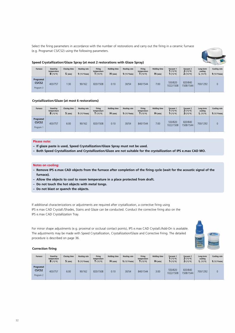
Select the firing parameters in accordance with the number of restorations and carry out the firing in a ceramic furnace
(e.g. Programat CS/CS2) using the following parameters.
If additional characterizations or adjustments are required after crystallization, a corrective firing using
IPS e.max CAD Crystall./Shades, Stains and Glaze can be conducted. Conduct the corrective firing also on the
IPS e.max CAD Crystallization Tray.
For minor shape adjustments (e.g. proximal or occlusal contact points), IPS e.max CAD Crystall./Add-On is available.
The adjustments may be made with Speed Crystallization, Crystallization/Glaze and Corrective Firing. The detailed
procedure is described on page 36.
Furnace
Programat
CS/CS2
Program 3
Stand-by temperature B [°C/°F]
403/757
Closing time
S [min]
1:30
Heating rate
t1 [°C/°F/min]
90/162
Firing temperature T1 [°C/°F]
820/1508
Holding time
H1 [min]
0:10
Heating rate
t2 [°C/°Fmin]
30/54
Firing temperature T2 [°C/°F]
840/1544
Holding time
H2 [min]
7:00
Vacuum 111 [°C/°F]12 [°C/°F]
550/8201022/1508
Vacuum 221 [°C/°F]22 [°C7°F]
820/840
1508/1544
Long-term cooling L [°C/°F]
700/1292
Cooling rate
tl [°C/°F/min]
0
Furnace
Programat
CS/CS2
Program 1
Stand-by temperature B [°C/°F]
403/757
Closing time
S [min]
6:00
Heating rate
t1 [°C/°F/min]
90/162
Firing temperature T1 [°C/°F]
820/1508
Holding time
H1 [min]
0:10
Heating rate
t2 [°C/°Fmin]
30/54
Firing temperature T2 [°C/°F]
840/1544
Holding time
H2 [min]
7:00
Vacuum 111 [°C/°F]12 [°C/°F]
550/8201022/1508
Vacuum 221 [°C/°F]22 [°C/°F]
820/840
1508/1544
Long-term cooling L [°C/°F]
700/1292
Cooling rate
tl [°C/°F/min]
0
Speed Crystallization/Glaze Spray (at most 2 restorations with Glaze Spray)
Crystallization/Glaze (at most 6 restorations)
Furnace
Programat
CS/CS2
Program 2
Stand-by temperature B [°C/°F]
403/757
Closing time
S [min]
6:00
Heating rate
t1 [°C/°F/min]
90/162
Firing temperature T1 [°C/°F]
820/1508
Holding time
H1 [min]
0:10
Heating rate
t2 [°C/°F/min]
30/54
Firing temperature T2 [°C/°F]
840/1544
Holding time
H2 [min]
3:00
Vacuum 111 [°C/°F]12 [°C/°F]
550/8201022/1508
Vacuum 221 [°C/°F]22 [°C/°F]
820/840
1508/1544
Long-term cooling L [°C/°F]
700/1292
Cooling rate
tl [°C/°F/min]
0
Correction firing
Please note:
– If glaze paste is used, Speed Crystallization/Glaze Spray must not be used.
– Both Speed Crystallization and Crystallization/Glaze are not suitable for the crystallization of IPS e.max CAD MO.
Notes on cooling:
– Remove IPS e.max CAD objects from the furnace after completion of the firing cycle (wait for the acoustic signal of the
furnace).
– Allow the objects to cool to room temperature in a place protected from draft.
– Do not touch the hot objects with metal tongs.
– Do not blast or quench the objects.

33
Stai
nin
g T
ech
niq
ue
Problem/Cause Before Firing
Application of the Glaze Spray
After Firing
Detailed view of the surface
Insufficient application of IPS e.max CAD Crystall./Glaze Spray
Problem:
Not enough Glaze Spray on the resto-
ration
Possible cause:
– Distance between the spray can and the
restoration too far
– Spraying too short
– Spray can not shaken sufficiently
– Spray can held not upright during
spraying Insufficient gloss or imcomplete glossy layer
Too much IPS e.max CAD Crystall./Glaze Spray applied
Problem:
Too much Glaze Spray on the restoration
Possible cause:
– Distance between the spray can and the
restoration too close
– Too much Glaze Spray applied
Loss of texture and too glossy surface
Example of incorrect Glaze Spray application
34
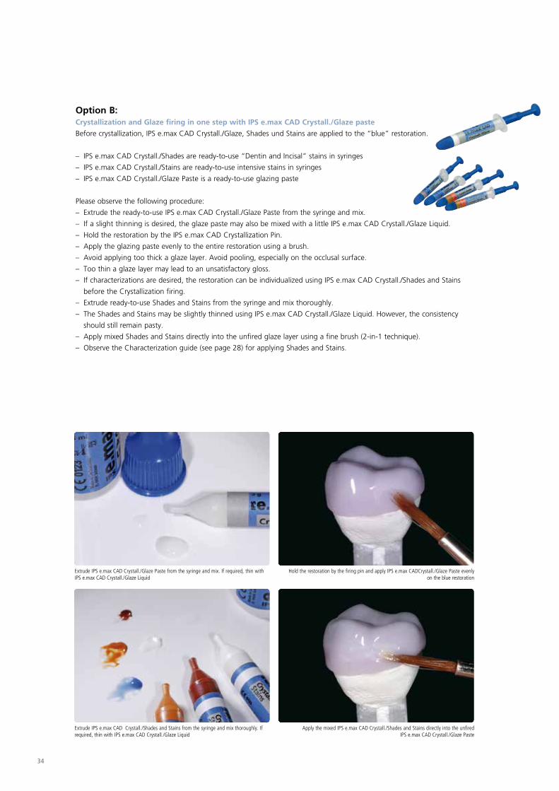
Apply the mixed IPS e.max CAD Crystall./Shades and Stains directly into the unfired IPS e.max CAD Crystall./Glaze Paste
Extrude IPS e.max CAD Crystall./Shades and Stains from the syringe and mix thoroughly. If required, thin with IPS e.max CAD Crystall./Glaze Liquid
Hold the restoration by the firing pin and apply IPS e.max CADCrystall./Glaze Paste evenly on the blue restoration
Extrude IPS e.max CAD Crystall./Glaze Paste from the syringe and mix. If required, thin with IPS e.max CAD Crystall./Glaze Liquid
Option B: Crystallization and Glaze firing in one step with IPS e.max CAD Crystall./Glaze paste
Before crystallization, IPS e.max CAD Crystall./Glaze, Shades und Stains are applied to the “blue” restoration.
– IPS e.max CAD Crystall./Shades are ready-to-use “Dentin and Incisal” stains in syringes
– IPS e.max CAD Crystall./Stains are ready-to-use intensive stains in syringes
– IPS e.max CAD Crystall./Glaze Paste is a ready-to-use glazing paste
Please observe the following procedure:
– Extrude the ready-to-use IPS e.max CAD Crystall./Glaze Paste from the syringe and mix.
– If a slight thinning is desired, the glaze paste may also be mixed with a little IPS e.max CAD Crystall./Glaze Liquid.
– Hold the restoration by the IPS e.max CAD Crystallization Pin.
– Apply the glazing paste evenly to the entire restoration using a brush.
– Avoid applying too thick a glaze layer. Avoid pooling, especially on the occlusal surface.
– Too thin a glaze layer may lead to an unsatisfactory gloss.
– If characterizations are desired, the restoration can be individualized using IPS e.max CAD Crystall./Shades and Stains
before the Crystallization firing.
– Extrude ready-to-use Shades and Stains from the syringe and mix thoroughly.
– The Shades and Stains may be slightly thinned using IPS e.max CAD Crystall./Glaze Liquid. However, the consistency
should still remain pasty.
– Apply mixed Shades and Stains directly into the unfired glaze layer using a fine brush (2-in-1 technique).
– Observe the Characterization guide (see page 28) for applying Shades and Stains.

35
After glazing and staining, the Combination firing (crystallization/glaze) is conducted in a compatible ceramic furnace
(e.g. Programat CS/C2). When placing the objects into the furnace and setting the firing parameters, please observe the
following points:
– Place the restoration including the pin into the center of the IPS e.max CAD Crystallization Tray.
– A maximum of 6 restorations can be positioned on the IPS e.max CAD Crystallization Tray and crystallized using the
Combination firing with IPS e.max CAD Crystall./Glaze Paste.
– If glaze paste is used, Speed Crystallization/Glaze Spray must not be used.
Stai
nin
g T
ech
niq
ue
Place the glazed and stained restoration into the centre of the IPS e.max CAD Crystallization Tray
Do not use a honey-combed tray for crystallization!
If additional characterizations or adjustments are required after crystallization, a corrective firing using
IPS e.max CAD Crystall./Shades and Stains and Glaze can be conducted. Conduct the corrective firing also on the
IPS e.max CAD Crystallization Tray.
For minor shape adjustments (e.g. proximal or occlusal contact points), IPS e.max CAD Crystall./Add-On is
available. The adjustments may be made with both Crystallization/Glaze and Corrective firing. The detailed
procedure is described on page 36.
Conduct the combination firing (crystallization/glaze) in a ceramic furnace (e.g. Programat CS/CS2) using the following
parameters:
Furnace
Programat
CS/CS2
Program 1
Stand-by temperature B [°C/°F]
403/757
Closing time
S [min]
6:00
Heating rate
t1 [°C/°F/min]
90/162
Firing temperature T1 [°C/°F]
820/1508
Holding time
H1 [min]
0:10
Heating rate
t2 [°C/°F/min]
30/54
Firing temperature T2 [°C/°F]
840/1544
Holding time
H2 [min]
7:00
Vacuum 111 [°C/°F]12 [°C/°F]
550/8201022/1508
Vacuum 221 [°C/°F]22 [°C/°F]
820/840
1508/1544
Long-term cooling L [°C/°F]
700/1292
Cooling rate
tl [°C/°F/min]
0
Furnace
Programat
CS/CS2
Program 2
Stand-by temperature B [°C/°F]
403/757
Closing time
S [min]
6:00
Heating rate
t1 [°C/°F/min]
90/162
Firing temperature T1 [°C/°F]
820/1508
Holding time
H1 [min]
0:10
Heating rate
t2 [°C/°F]
30/54
Firing temperature T2 [°C/°F]
840/1544
Holding time
H2 [°C/°F]
3:00
Vacuum 111 [°C/°F]12 [°C/°F]
550/8201022/1508
Vacuum 221 [°C/°F]22 [°C/°F]
820/840
1508/1544
Long-term cooling L [°C/°F]
700/1292
Cooling rate
tl [°C/°F/min]
0
Crystallization/Glaze
Correction firing
Please note:
– If glaze paste is used, Speed Crystallization/Glaze Spray must not be used.
– These firing parameters are not suitable for the crystallization of IPS e.max CAD MO!
Notes on cooling:
– Remove IPS e.max CAD objects from the furnace after completion of the firing cycle (wait for the acoustic signal of the
furnace).
– Allow the objects to cool to room temperature in a place protected from draft.
– Do not touch the hot objects with metal tongs.
– Do not blast or quench the objects.

36
Optional
Adjustments with IPS e.max CAD Crystall./Add-On
For minor shape adjustments (e.g. proximal or occlusal contact points), IPS e.max CAD Crystall./Add-On is
available . The adjustments may be made with both Crystallization/Glaze and Corrective firing.
Processing:
– Mix IPS e.max CAD Crystall./Add-On with IPS e.max CAD Crystall/Add-On Liquid to an easy-to-contour
consistency.
– Ensure even mixing of the add-on material and the liquid in order to achieve an optimum firing result.
– Apply the mixed add-on material directly on the unfired Glaze Paste and/or Shades and Stains in the areas to be
adjusted and fire.
– If the Glaze Spray is used, apply the Shades and Stains first. Subsequently, supplement the missing areas using Add-On.
Apply the Glaze Spray immediately after the application of the Add-On and fire.
– Conduct the Combination firing (crystallization/glaze HT/LT) after the application of Add-On on the «blue», non-
crystallized restoration.
– Conduct the Corrective firing if Add-On is applied on an already crystallized restoration.
– Speed Crystallization/Glaze Spray must not be used in conjunction with the Add-On.
Mix IPS e.max CAD Crystall/Add-On with IPS e.max CAD Crystall/Add-On Liquid to an easy-to-contour consistency.
Application of the mixed Add-On on the blue restoration before crystallization
Application of the mixed Add-On on the crystallized restoration
Firing parameters for the Corrective firing
Furnace
Programat
CS/CS2
Program 2
Stand-by temperature B [°C/°F]
403/757
Closing time
S [min]
6:00
Heating ratet1
[°C/°F/min]
90/162
Firing tempera-
ture T1 [°C/°F]
820/1508
Holding time
H1 [min]
0:10
Heating rate t2
[°C/°F/min]
30/54
Firing tempera-
ture T2 [°C/°F]
840/1544
Holding time
H2 [min]
3:00
Vacuum 111 [°C/°F]12 [°C/°F]
550/8201022/1508
Vacuum 221 [°C/°F]22 [°C/°F]
820/840
1508/1544
Long-term cooling L [°C/°F]
700/1292
Cooling rate tl
[°C/°F/min]
0
Firing parameters Crystallization / Glaze HT/LT
Furnace
Programat
CS/CS2
Program 1
Stand-by temperature B [°C/°F]
403/757
Closing time
S [min]
6:00
Heating ratet1
[°C/°F/min]
90/162
Firing tempera-
ture T1 [°C/°F]
820/1508
Holding time
H1 [min]
0:10
Heating rate t2
[°C/°F/min]
30/54
Firing tempera-
ture T2 [°C°/F]
840/1544
Holding time
H2 [min]
7:00
Vacuum 111 [°C/°F]12 [°C/°F]
550/8201022/1508
Vacuum 221 [°C/°F]22 [°C/°F]
820/840
1508/1544
Long-term cooling L [°C/°F]
700/1292
Cooling rate tl
[°C/°F/min]
0

37
Completion of the Restoration
Once the IPS e.max CAD restoration has cooled to room temperature, proceed with the following steps:
– Remove the restoration from the hardened auxiliary firing paste.
– Remove any residue with ultrasound in a water bath and/or with steam.
– Do not blast the restoration with Al2O3 or glass polishing beads.
– Final try-in of the restoration before cementation.
– If adjustments by grinding are required, make sure that no overheating of glass-ceramic occurs.
– Use fine-grained diamonds (< 60 µm) for finishing, followed by rubber polishers at low speed and limited pressure. For
the selection of the appropriate grinding tools, refer to the Ivoclar Vivadent Flow Chart “Recommended grinding tools –
chairside”.
– Finally, polish the adjusted areas to a high gloss (e.g. using OptraFine).
– Thoroughly clean the restoration.
Remove the cool restoration from the hardened IPS Object Fix Putty or Flow Remove residue with ultrasound in a water bath…
... or with steam. Final try-in of the restoration before cementation
Stai
nin
g T
ech
niq
ue

38
e.max® CAD Cut-back Technique
IPS
To fabricate highly esthetic restorations, especially in the anterior region, the incisal/occlusal third may be
veneered using IPS e.max Ceram nano-fluorapatite layering ceramic. The individual working steps are briefly
described below. For a detailed description of the materials used and the individual working steps, please refer
to the Instructions for Use of IPS e.max CAD labside.
V E R A R B E I T U N G S A N L E I T U N G
CAD
LABSID E
all ceramicsall you need
Partially reduced IPS e.max CAD restorations fitted on the
model.
The cut-back may be carried out by using a corresponding
milling procedure in the CAD/CAM unit (crown on tooth
11) or by manual reduction (veneer on tooth 21) in the
blue state.
For crystallization, place the partially reduced
IPS e.max CAD restorations directly on the IPS e.max CAD
Crystallization Tray using IPS Object Fix Putty or Flow.
Conduct the wash firing using IPS e.max Ceram Glaze,
Shades and Essences.

39
Cu
t-b
ack
Tech
niq
ue
Completion of the anatomical shape of the reduced areas
using IPS e.max Ceram Incisal and Opal materials.
Finish the restoration with diamonds and give it a true-to-
nature shape and surface structure. Finally, conduct glaze
firing using IPS e.max Ceram Glaze.
IPS e.max CAD LT veneer and anterior crown after glaze firing (partially reduced and veneered with IPS e.max Ceram)
The dental lab work was carried out by J. Seger, Ivoclar Vivadent AG, Liechtenstein

40
e.max® CAD – Seating and Follow-Up Care
IPS
Possibilities for Cementation
Esthetic cementation options are crucial for the harmonic shade effect of all-ceramic restorations. Depending on the
indication, IPS e.max CAD restorations may be placed using the adhesive, self-adhesive or the conventional cementation
technique.
– For the adhesive cementation of IPS e.max CAD restorations, Variolink® II, Variolink® Veneer or Multilink® Automix are
the ideal composites.
– For the self-adhesive cementation of IPS e.max CAD restorations, we recommend using SpeedCEM®.
– If IPS e.max CAD restorations are cemented conventionally, we recommend using the glass-ionomer cement
Vivaglass® CEM.
Definition
• Adhesive cementation
In the adhesive cementation technique, bonding is achieved also through mechanical adhesion, but mainly through
chemical/micromechanical adhesion between the cementation material and the restoration and between the cementa-
tion material and the preparation. Due to the chemical/micromechanical bonding, a retentive preparation is not required.
Depending on the cementation material, specific adhesive systems are used on prepared teeth in order to achieve the
micromechanical bond to dentin or enamel.
Adhesive cementation increases the “(overall) strength” of the incorporated all-ceramic restoration.
• Self-adhesive cementation
The cementation material shows self-etching properties on the tooth, but not on the restoration. Therefore, the tooth
surface does not need to be specifically conditioned. The bond is generated in part by micromechanical/chemical
adhesion. In order to achieve sufficient bonding strengths, a retentive preparation is recommended.
• Conventional cementation
In the conventional cementation technique, the bond is achieved nearly exclusively through mechanical friction between
the cementation material and the restoration as well as between the cementation material and the preparation. In order
to obtain the required mechanical friction, a retentive preparation showing a preparation angle of approximately 4–6° is
required.

41
Material
Indication
Cementation method
Blasting
Etching
Conditioning / silanization
Cementation system
self-adhesive / conventional *
Variolink® II,Multilink®
Automix
SpeedCEM
Vivaglass® CEM
IPS e.max CAD
Veneers,inlays, onlays, partial crowns
Anterior and posterior crowns
adhesive adhesive
20 sec with IPS Ceramic Etching Gel
60 sec with Monobond® Plus
––
Variolink® Veneer, Variolink® II,
Multilink®
Automix
Lithium disilicate glass-ceramic
Seat
ing
an
d F
ollo
w-U
p C
are
Seating
The conditioning of the restoration and the preparation depends on the cementation technique applied and the cementa-
tion material. For the cementation of IPS e.max CAD restorations, you may choose between the tried-and-tested cementa-
tion materials from Ivoclar Vivadent according to the indication.
The following list describes the basic working steps to prepare the seating. For a detailed description of the procedure,
please refer to the respective Instructions for Use of the cementation material used.
a. Conditioning of the restoration
Conditioning of the ceramic surface to prepare the cementation is decisive for generating a sound bond between the
cementation material and the all-ceramic restoration. The conditioning procedure depends on the choice of cementation
material according to the indication.
* Conventional cementation is done without conditioning The range of products on offer may vary from country to country
Please observe the corresponding Instructions for Use.
42
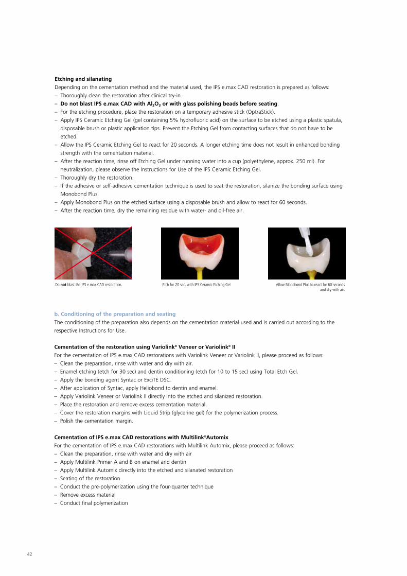
Etching and silanating
Depending on the cementation method and the material used, the IPS e.max CAD restoration is prepared as follows:
– Thoroughly clean the restoration after clinical try-in.
– Do not blast IPS e.max CAD with Al2O3 or with glass polishing beads before seating.
– For the etching procedure, place the restoration on a temporary adhesive stick (OptraStick).
– Apply IPS Ceramic Etching Gel (gel containing 5% hydrofluoric acid) on the surface to be etched using a plastic spatula,
disposable brush or plastic application tips. Prevent the Etching Gel from contacting surfaces that do not have to be
etched.
– Allow the IPS Ceramic Etching Gel to react for 20 seconds. A longer etching time does not result in enhanced bonding
strength with the cementation material.
– After the reaction time, rinse off Etching Gel under running water into a cup (polyethylene, approx. 250 ml). For
neutralization, please observe the Instructions for Use of the IPS Ceramic Etching Gel.
– Thoroughly dry the restoration.
– If the adhesive or self-adhesive cementation technique is used to seat the restoration, silanize the bonding surface using
Monobond Plus.
– Apply Monobond Plus on the etched surface using a disposable brush and allow to react for 60 seconds.
– After the reaction time, dry the remaining residue with water- and oil-free air.
b. Conditioning of the preparation and seating
The conditioning of the preparation also depends on the cementation material used and is carried out according to the
respective Instructions for Use.
Cementation of the restoration using Variolink® Veneer or Variolink® II
For the cementation of IPS e.max CAD restorations with Variolink Veneer or Variolink II, please proceed as follows:
– Clean the preparation, rinse with water and dry with air.
– Enamel etching (etch for 30 sec) and dentin conditioning (etch for 10 to 15 sec) using Total Etch Gel.
– Apply the bonding agent Syntac or ExciTE DSC.
– After application of Syntac, apply Heliobond to dentin and enamel.
– Apply Variolink Veneer or Variolink II directly into the etched and silanized restoration.
– Place the restoration and remove excess cementation material.
– Cover the restoration margins with Liquid Strip (glycerine gel) for the polymerization process.
– Polish the cementation margin.
Cementation of IPS e.max CAD restorations with Multilink®Automix
For the cementation of IPS e.max CAD restorations with Multilink Automix, please proceed as follows:
– Clean the preparation, rinse with water and dry with air
– Apply Multilink Primer A and B on enamel and dentin
– Apply Multilink Automix directly into the etched and silanated restoration
– Seating of the restoration
– Conduct the pre-polymerization using the four-quarter technique
– Remove excess material
– Conduct final polymerization
Do not blast the IPS e.max CAD restoration. Etch for 20 sec. with IPS Ceramic Etching Gel Allow Monobond Plus to react for 60 seconds and dry with air.
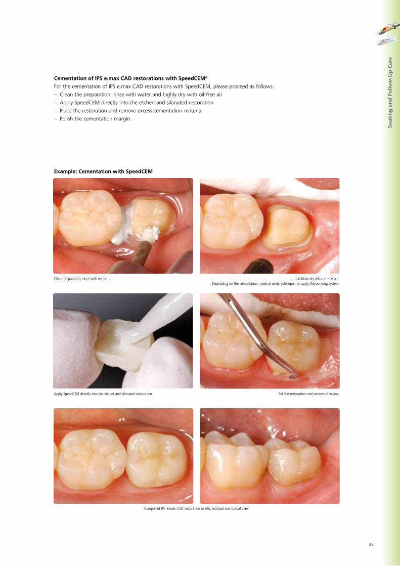
43
Clean preparation, rinse with water … … and blow dry with oil-free air.Depending on the cementation material used, subsequently apply the bonding system
Apply SpeedCEM directly into the etched and silanated restoration Set the restoration and remove of excess
Completed IPS e.max CAD restoration in situ, occlusal and buccal view
Seat
ing
an
d F
ollo
w-U
p C
are
Example: Cementation with SpeedCEM
Cementation of IPS e.max CAD restorations with SpeedCEM®
For the cementation of IPS e.max CAD restorations with SpeedCEM, please proceed as follows:
– Clean the preparation, rinse with water and highly dry with oil-free air
– Apply SpeedCEM directly into the etched and silanated restoration
– Place the restoration and remove excess cementation material
– Polish the cementation margin.
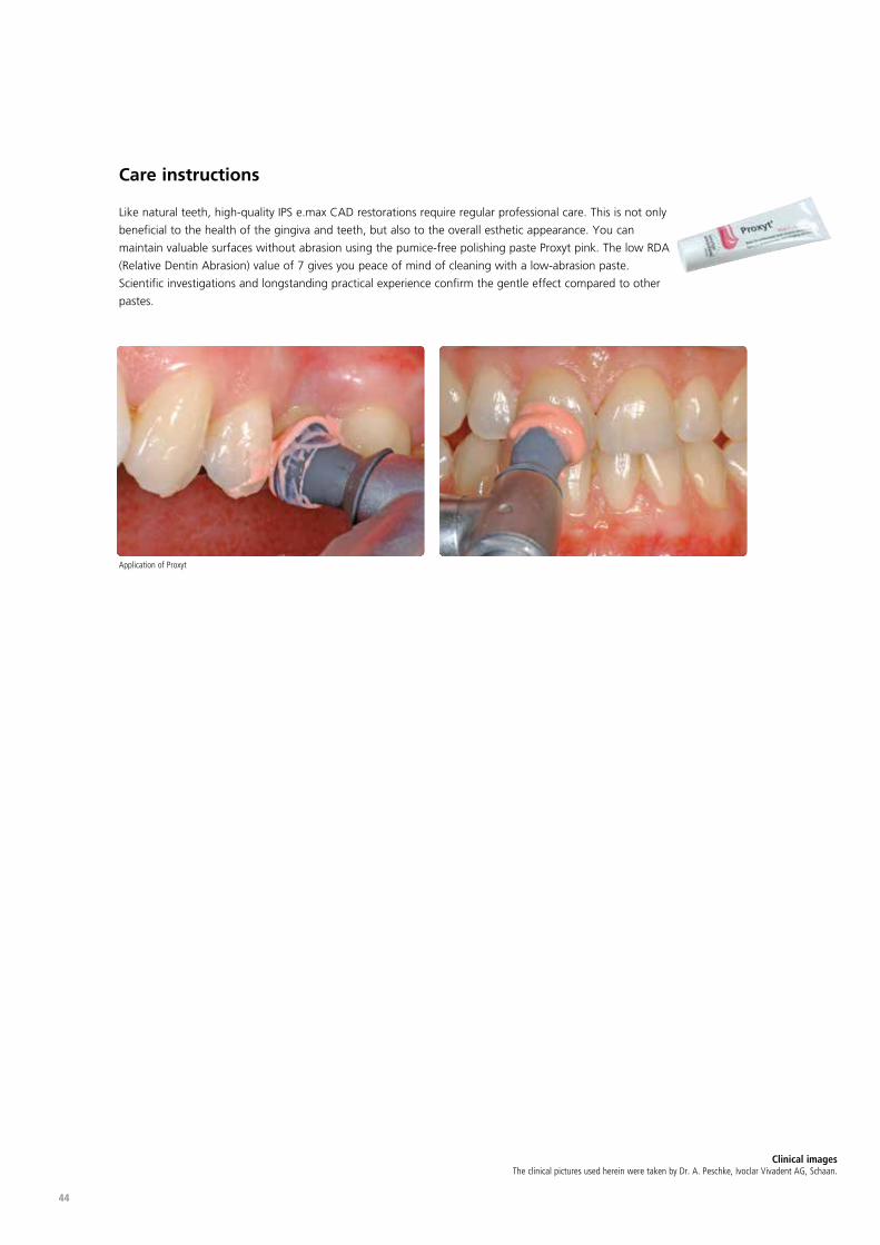
44
Care instructions
Like natural teeth, high-quality IPS e.max CAD restorations require regular professional care. This is not only
beneficial to the health of the gingiva and teeth, but also to the overall esthetic appearance. You can
maintain valuable surfaces without abrasion using the pumice-free polishing paste Proxyt pink. The low RDA
(Relative Dentin Abrasion) value of 7 gives you peace of mind of cleaning with a low-abrasion paste.
Scientific investigations and longstanding practical experience confirm the gentle effect compared to other
pastes.
Application of Proxyt
Clinical images The clinical pictures used herein were taken by Dr. A. Peschke, Ivoclar Vivadent AG, Schaan.

45
If a plaster working model is used to work
with, which type of plaster should be used to
fabricate the model?
The directions of the manufacturers of the CAD/
CAM system in use should be observed in the fab-
rication of the models. The following basic rule
applies: Depending on the CAD/CAM system and
equipment, special plasters may have to be used
for the fabrication of models and dies to ensure
the quality of the scan. If a special scanning
plaster is unavailable, models and dies can be
fabricated with high-strength stone, which is
sprayed with IPS Contrast Spray chairside or
IPS Contrast Spray labside immediately before the
scanning procedure.
What kind of preparation requirements must
the die demonstrate in order to produce
accurately fitting restorations?
The preparation guidelines for all-ceramic restora-
tions apply to IPS e.max CAD. The thickness of the
incisal edge of prepared anterior teeth (upper and
lower) requires special attention. The prepared
incisal edge should be at least as thick as the
diameter of the bur used in the cavity. The
corresponding instructions of the manufacturer
regarding the dimensions of the grinding
instruments must be observed during preparation.
Can an incisal edge which has become too
thin during preparation be adjusted prior to
scanning to avoid complicating the try-in
procedure after machining?
In cases such as these, we recommend blocking
out the incisal edge of the prepared die until the
thickness matches that of the bur.
Why is it necessary to determine the shade of
the tooth after preparation?
It is necessary to know the
shade of the prepared tooth
because, depending on the
translucency level of the
block used, the shade of the
prepared tooth may have an influence on the
seated all-ceramic restoration. The appropriate
block can be selected using the IPS Natural Die
shade guide.
In what situations are IPS e.max CAD HT
blocks used?
Given their high translucency, HT blocks are
ideally suitable for the fabrication of smaller
restorations (e.g. inlays and onlays). Restorations
made of HT blocks convince users with their true-
to-nature chameleon effect and the exceptional
adaption to the remaining tooth structure. The
brightness may be lower if translucent blocks are
used to fabricate larger restorations (e.g. crowns).
In such cases, it is recommended to use blocks
with lower translucency levels (IPS e.max CAD LT).
In which situations are IPS e.max CAD LT
blocks used?
Due to their high brightness values compared to
the HT blocks, LT blocks are ideally suitable for
the fabrication of larger restorations (e.g. anterior
and posterior crowns). IPS e.max CAD LT restora-
tions convince users with their lifelike brightness
value and chroma. This prevents the incorporated
restorations from greying.
Does the occlusal surface of IPS e.max CAD
restorations have to be ground after the
CAD/CAM processing?
Yes. In order to smooth out the
surface structure created by the
CAD/CAM milling, the occlusal
surface and particularly the func-
tional areas which show antago-
nist contact must be sur-
face-ground with fine diamonds.
Should manual adjustments with grinding
instruments be done before or after
crystallization?
Corrections by grinding should always be carried
out on the blue restoration prior to crystallization.
In doing so, it must be ensured that the restora-
tion is processed using only suitable grinding
instruments, low speed and light pressure to
prevent delamination and chipping at the edges in
particular.
e.max® CAD – Questions and answers
IPS

46
Can machined IPS e.max CAD restorations in
the pre-crystallized (blue) state be
completely finished and then just crystallized
and glazed?
Milled IPS e.max CAD restorations should be care-
fully tried in and finished in their pre-crystallized
(“blue”) state. In the blue state, special attention
must be paid to the restoration margins. The
margins should be created in relation to the
preparation and the thickness of the restoration.
Do IPS e.max CAD restorations shrink during
crystallization?
No. During the crystallization process, the micro-
structure becomes transformed and a densifica-
tion of 0.2 % takes place. The CAD software
takes the densification factor into account.
Therefore, the milled IPS e.max CAD restorations
demonstrate precision of fit after crystallization.
No further manual adjustments are necessary.
Why does the auxiliary firing paste
IPS Object Fix Putty or Flow have to be used
during the crystallization process?
The auxiliary firing paste ideally supports
IPS e.max CAD restorations during crystallization,
which ensures that the restorations demonstrate
optimum accuracy of fit.
Can firing pastes other than
IPS Object Fix Putty or Flow be used in the
crystallization process?
IPS Object Fix Putty and Flow has been specially
developed for the crystallization of IPS e.max CAD
restorations. The expansion behaviour has been
optimally coordinated with IPS e.max CAD. In
other words, the consistency before and after the
crystallization allows the paste to be easily applied
and cleanly removed. Given their composition,
pastes of other manufacturers may cause damage
to IPS e.max CAD. Furthermore, easy removal may
not always be possible.
How can the restoration be filled with
IPS Object Fix Putty?
IPS Object Fix Putty can be filled into the inner
aspect of the restoration with the help of a plastic
spatula (e.g. OptraSculpt). Alternatively, a small
amount of IPS Object Fix Putty may be rolled
between the fingers and then pressed into the
restoration. IPS Object Fix Putty excess which is
forced out when the IPS e.max CAD Crystallization
Pin is pressed into the putty can also be adapted
with a plastic spatula or the fingers. Always make
sure, however, that the outer surface of the resto-
ration is not contaminated with IPS Object Fix.
How are contaminations with IPS Object Fix
Putty or Flow on the outer surface of the
restorations best removed before
crystallization?
A brush, a cotton swab or a microbrush
dampened with water can be used for cleaning.
It must be made sure that any residue has been
removed before Shades, Stains or Glaze are
applied in order to prevent the residue from being
burned in.
How can a premature drying of the
IPS Object Fix Putty or Flow in the syringe be
prevented?
In order to avoid a premature loss of moisture of
the firing pastes, remove the syringe from the
aluminium bag only directly before initial use.
Close the syringe immediately after usage. If the
syringe is not used for a longer period of time, it
can be stored in a resealable plastic bag together
with a moist paper tissue.

47
Can other firing trays, e.g. honey-combed
trays, be used for the crystallization of
IPS e.max CAD?
No other firing trays should be
used. The IPS e.max CAD
Crystallization Tray contained in
the assortment stores the heat
necessary for slow and above all
tension-free cooling of the
glass-ceramic. Other firing trays,
e.g. honey-combed tray, cannot
store the heat and therefore cool down too quickly.
Can furnaces other than the ones from
Ivoclar Vivadent be used to crystallize
IPS e.max CAD restorations?
The crystallization of IPS e.max CAD is specially
coordinated with the Ivoclar Vivadent ceramic
furnaces (e.g. Programat CS). If you would like to
use other ceramic furnaces, please consult Ivoclar
Vivadent about their compatibility with IPS e.max
CAD. It is important to note that not every
ceramic furnace can be used for crystallization.
Ceramic furnaces which, for example, do not
feature a controlled (long-term) cooling mode or
vacuum cannot be used for this purpose.
Can IPS e.max CAD Crystall./Add-On also be
fired with the parameters Speed
Crystallization/Glaze Spray?
No. Since the IPS e.max CAD Crystall./Add-On
Liquid contains organic components that only
slowly evaporate during pre-drying, the para-
meters Speed Crystallization/Glaze Spray cannot
be used due to the short closing time.
Can the IPS e.max CAD Crystall./Glaze Paste
also be fired with the parameters Speed
Crystallization/Glaze Spray?
No. Since the IPS e.max CAD Crystall./Glaze Paste
contains organic components that only slowly
evaporate during pre-drying, the parameters
Speed Crystallization/Glaze Spray cannot be used
due to the short closing time.
Can IPS Empress Universal Shades, Stains and
Glaze be used for IPS e.max CAD?
IPS Empress Universal Shades, Stains and Glaze
were specially developed for and coordinated with
the IPS Empress System and are therefore not
suitable for IPS e.max products.
What must be considered after the firing of
IPS e.max CAD?
In order to prevent tensions within the ceramic,
remove the restoration from the furnace only
after the firing cycles have been completed (wait
for the acoustic signal of the ceramic furnace.
Allow the objects to cool to room temperature in
a place protected from draft and do not touch
them with metal tongs during that time. Do not
blast or quench the objects.
Can IPS e.max CAD restorations be blasted
with Al2O3 or glass polishing beads (on the
cavity side) as a preparation for the seating?
IPS e.max CAD restorations must not be blasted
with Al2O3 or glass polishing beads before
placement, as this damages the ceramic surface
and significantly reduces the strength.
How must the internal (bonding) surface
of the IPS e.max CAD restorations be
conditioned before cementation?
The internal (bonding) surfaces of IPS e.max CAD
restorations must always be etched with 5%
hydrofluoric acid etching gel (IPS Ceramic Etching
Gel) for 20 seconds, of whether they are cement-
ed with adhesive, self-adhesive or conventional
methods. The resulting retentive pattern enables
an enhanced bond both with adhesives and
self-adhesives, as well as conventional bonding
agents. After etching, the glass-ceramics are
silanized using Monobond Plus when adhesive
and self-adhesive cementation is used.

48
e.max® CAD – Table on Block Selection
IPS
The blocks are selected on the basis of the desired tooth shade (Bleach BL or A-D), the determined shade of the prepara-
tion (ND 1- ND 9), and/or abutment shade, as well as the desired processing technique. The following procedure results in
the selection of the appropriate block:
1. Select the column with the desired tooth shade.
2. Select the line with the shade of the preparation.
3. Select the adequate block in accordance with the desired processing technique (staining or cut-back technique) in the
intersection field.
4. If a certain combination is not possible (e.g. HT block on a dark preparation), select a block with a lower translucency.
– The recommendations for the block selection correlate with the indications as well as the preparation
guidelines and minimum layer thicknesses.
– In case of shade deviations, adjust the restoration shade by means of characterization with IPS e.max CAD
Crystall./ Shades and Stains.
– If (highly) translucent blocks are used, the layer thickness and die shade must be carefully observed.
– With thicker layers, a block with lower translucency must be selected to prevent a loss in brightness
(graying).
Shade of the prepared naturaltooth
IPS Natural Die Material BL1 BL2 BL3 BL4 A1 A2 A3 A3.5 A4 B1 B2 B3 B4 C1 C2 C3 C4 D2 D3 D4
Desired Tooth Shade: Bleach BL and A-D Shade Guide
HT BL1 HT BL2 HT BL3 HT BL4 HT A1 HT A2 HT A3 HT A3.5 HT A4 HT B1 HT B2 HT B3 HT B4 HT C1 HT C2 HT C3 HT C4 HT D2 HT D3 HT D4
LT BL1 LT BL2 LT BL3 LT BL4 LT A1 LT A2 LT A3 LT A3.5 LT A4 LT B1 LT B2 LT B3 LT B4 LT C1 LT C2 LT C3 LT C4 LT D2 LT D3 LT D4
HT BL1 HT BL2 HT BL3 HT BL4 HT A1 HT A2 HT A3 HT A3.5 HT A4 HT B1 HT B2 HT B3 HT B4 HT C1 HT C2 HT C3 HT C4 HT D2 HT D3 HT D4
LT BL1 LT BL2 LT BL3 LT BL4 LT A1 LT A2 LT A3 LT A3.5 LT A4 LT B1 LT B2 LT B3 LT B4 LT C1 LT C2 LT C3 LT C4 LT D2 LT D3 LT D4
HT BL1 HT BL2 HT BL3 HT BL4 HT BL2 HT A2 HT A3 HT A3.5 HT A4 HT BL2 HT B2 HT B3 HT B4 HT C1 HT C2 HT C3 HT C4 HT D2 HT D3 HT D4
LT BL1 LT BL2 LT BL3 LT BL4 LT A1 LT A2 LT A3 LT A3.5 LT A4 LT B1 LT B2 LT B3 LT B4 LT C1 LT C2 LT C3 LT C4 LT D2 LT D3 LT D4
HT BL2 HT A1 HT A3.5 HT A4 HT BL1 HT BL2 HT B2 HT B2 HT BL2 HT C1 HT C2 HT B4 HT B1 HT D2 HT D2
LT BL1 LT BL2 LT BL4 LT BL 3 LT A1 LT A2 LT A3.5 LT A4 LT B1 LT B2 LT B3 LT B4 LT C1 LT C2 LT C3 LT C4 LT D2 LT D3 LT D4
HT B3 HT A4 HT BL2 HT BL2 HT BL1 HT B1 HT B3 HT C2 HT BL1 HT B1 HT D2
LT BL 2 LT A1 LT A2 LT A3 LT BL 2 LT A1 LT A2 LT A3 LT A4 LT BL3 LT B1 LT B2 LT B3 LT C1 LT B2 LT C3 LT C4 LT D2 LT B2 LT D3
HT BL1 HT BL1 HT A3.5 HT A4 HT BL1 HT BL1 HT BL2 HT BL2 HT A1 HTA3 HT B3 HT BL1 HT A2 HT C1
LT BL1 LBL2 LT BL4 LT BL2 LT A1 LT A2 LT A3 LT A4 LT BL3 LT B1 LT B2 LT B3 LT C1 LT B2 LT C3 LT C4 LT D2 LT B2 LT D3
HT BL1 HT BL1 HT BL1 HT A3 HT BL1 HT BL2 HT B1 HT B2 HT B3 HT BL1 HT BL2 HT BL2
LT BL1 LBL2 LT BL4 LT BL1 LT A1 LT A2 LT A3 LT A4 LT BL3 LT B1 LT B2 LT B3 LT C1 LT B2 LT C3 LT C4 LT D2 LT B2 LT D3
HT BL1 HT BL1 HT A1 HT A3 HT A3.5 HT A4 HT B1 HT BL2 HT BL2
LT BL1 LBL2 LT BL4 LT BL1 LT A1 LT A2 LT A3 LT A4 LT BL3 LT B1 LT B2 LT B3 LT C1 LT B2 LT C3 LT C4 LT D2 LT B2 LT D3
HT B2 HT C1 HT B2 HT C3 HT C4 HT D2 HT B2 HT D2
LT A3 LT A4 LT BL2 LT C1 LT B2 LT C3 LT C4 LT D2 LT B2 LT D2
ZrO2 Abutment (unshaded)
ND 1
ND 2
ND 3
ND 4*
ND 5*
ND 6*
ND 7*
ND 8*
ND 9*
Ti Abutment*
2
1➩
➩

49
* in
ord
er to
ach
ieve
the
desir
ed to
oth
shad
e, th
e pr
epar
atio
n ha
s to
be
light
ened
. If t
his
cann
ot b
e do
ne, t
he re
stor
atio
n ca
n be
fabr
icate
d in
the
labo
rato
ry (l
ayer
ing
tech
niqu
e) u
sing
opaq
ue IP
S e.
max
CAD
MO
blo
cks.
Shad
e o
f th
e p
rep
ared
nat
ura
l to
oth
IPS
Nat
ura
l Die
Mat
eria
l
BL1
BL2
BL3
BL4
A1
A2
A3
A3.
5
A4
B1
B2
B3
B4
C1
C2
C3
C4
D2
D3
D4
Des
ired
To
oth
Sh
ade:
Ble
ach
BL
and
A-D
Sh
ade
Gu
ide
HT
BL1
HT
BL2
HT
BL3
HT
BL4
HT
A1
HT
A2
HT
A3
HT
A3.
5 H
T A
4 H
T B1
H
T B2
H
T B3
H
T B4
H
T C1
H
T C2
H
T C3
H
T C4
H
T D
2 H
T D
3 H
T D
4
LT
BL1
LT B
L2
LT B
L3
LT B
L4
LT A
1 LT
A2
LT A
3 LT
A3.
5 LT
A4
LT B
1 LT
B2
LT B
3 LT
B4
LT C
1 LT
C2
LT C
3 LT
C4
LT D
2 LT
D3
LT D
4
HT
BL1
HT
BL2
HT
BL3
HT
BL4
HT
A1
HT
A2
HT
A3
HT
A3.
5 H
T A
4 H
T B1
H
T B2
H
T B3
H
T B4
H
T C1
H
T C2
H
T C3
H
T C4
H
T D
2 H
T D
3 H
T D
4
LT
BL1
LT B
L2
LT B
L3
LT B
L4
LT A
1 LT
A2
LT A
3 LT
A3.
5 LT
A4
LT B
1 LT
B2
LT B
3 LT
B4
LT C
1 LT
C2
LT C
3 LT
C4
LT D
2 LT
D3
LT D
4
HT
BL1
HT
BL2
HT
BL3
HT
BL4
HT
BL2
HT
A2
HT
A3
HT
A3.
5 H
T A
4 H
T BL
2 H
T B2
H
T B3
H
T B4
H
T C1
H
T C2
H
T C3
H
T C4
H
T D
2 H
T D
3 H
T D
4
LT
BL1
LT B
L2
LT B
L3
LT B
L4
LT A
1 LT
A2
LT A
3 LT
A3.
5 LT
A4
LT B
1 LT
B2
LT B
3 LT
B4
LT C
1 LT
C2
LT C
3 LT
C4
LT D
2 LT
D3
LT D
4
HT
BL2
HT
A1
HT
A3.
5 H
T A
4 H
T BL
1 H
T BL
2 H
T B2
H
T B2
H
T BL
2 H
T C1
H
T C2
H
T B4
H
T B1
H
T D
2 H
T D
2
LT B
L1
LT B
L2
LT B
L4
LT B
L 3
LT A
1 LT
A2
LT A
3,5
LT A
4 LT
B1
LT B
2 LT
B3
LT B
4 LT
C1
LT C
2 LT
C3
LT C
4 LT
D2
LT D
3 LT
D4
HT
B3
HT
A4
HT
BL2
HT
BL2
HT
BL1
HT
B1
HT
B3
HT
C2
HT
BL1
HT
B1
HT
D2
LT
BL 2
LT
A1
LT A
2 LT
A3
LT B
L 2
LT A
1 LT
A2
LT A
3 LT
A4
LT B
L3
LT B
1 LT
B2
LT B
3 LT
C1
LT B
2 LT
C3
LT C
4 LT
D2
LT B
2 LT
D3
HT
BL1
HT
BL1
HT
A3.
5 H
T A
4
HT
BL1
HT
BL1
HT
BL2
HT
BL2
HT
A1
HTA
3 H
T B3
H
T BL
1 H
T A
2 H
T C1
LT B
L1
LBL2
LT
BL4
LT
BL2
LT
A1
LT A
2 LT
A3
LT A
4 LT
BL3
LT
B1
LT B
2 LT
B3
LT C
1 LT
B2
LT C
3 LT
C4
LT D
2 LT
B2
LT D
3
HT
BL1
HT
BL1
HT
BL1
HT
A3
HT
BL1
HT
BL2
H
T B1
H
T B2
H
T B3
H
T BL
1 H
T BL
2 H
T BL
2
LT B
L1
LBL2
LT
BL4
LT
BL1
LT
A1
LT A
2 LT
A3
LT A
4 LT
BL3
LT
B1
LT B
2 LT
B3
LT C
1 LT
B2
LT C
3 LT
C4
LT D
2 LT
B2
LT D
3
HT
BL1
HT
BL1
HT
A1
HT
A3
HT
A3.
5 H
T A
4 H
T B1
H
T BL
2 H
T BL
2
LT B
L1
LBL2
LT
BL4
LT
BL1
LT
A1
LT A
2 LT
A3
LT A
4 LT
BL3
LT
B1
LT B
2 LT
B3
LT C
1 LT
B2
LT C
3 LT
C4
LT D
2 LT
B2
LT D
3
H
T B2
H
T C1
H
T B2
H
T C3
H
T C4
H
T D
2 H
T B2
H
T D
2
LT A
3 LT
A4
LT
BL2
LT
C1
LT B
2 LT
C3
LT C
4 LT
D2
LT B
2 LT
D2
ZrO
2 A
bu
tmen
t (u
nsh
aded
)
ND
1
ND
2
ND
3
ND
4*
ND
5*
ND
6*
ND
7*
ND
8*
ND
9*
Ti A
bu
tmen
t*

50
Ch
arac
teri
zati
on
s -
IPS
e.m
ax C
AD
Cry
stal
l./Sh
ades
an
d S
tain
s o
n IP
S e.
max
CA
D
Indi
vidu
al c
hara
cter
izat
ions
and
sha
de a
djus
tmen
ts o
f IP
S e.
max
CA
D r
esto
ratio
ns a
re a
chie
ved
with
IPS
e.m
ax C
AD
Cry
stal
l./Sh
ades
and
IPS
e.m
ax C
AD
Cry
stal
l./St
ains
.
wh
ite,
cre
me,
su
nse
t, c
op
per
, oliv
e, k
hak
i, m
aho
gan
y
A–D
IPS
e.m
ax C
AD
Cry
stal
l./Sh
ade
IPS
e.m
ax C
AD
Cry
stal
l./Sh
ade
Inci
sal
IPS
e.m
ax C
AD
Cry
stal
l./St
ains
A1
SH 1
SH I1
A2
SH 1
SH I1
A3
SH 1
SH I1
A3.
5
SH 1
SH I2
A4
SH 1
SH
I2
B1
SH 2
SH I1
B2
SH 2
SH I1
B3
SH 2
SH I1
B4
SH 2
SH I1
C1
SH 3
SH I2
C2
SH 3
SH I2
C3
SH 3
SH I2
C4
SH 3
SH I2
D2
SH 4
SH I2
D3
SH 4
SH I2
D4
SH 4
SH I2
wh
ite,
cre
me,
su
nse
t, c
op
per
, oliv
e,
khak
i, m
aho
gan
y
Ble
ach
BL
IPS
e.m
ax C
AD
Cry
stal
l./Sh
ade
IPS
e.m
ax C
AD
Cry
stal
l./Sh
ade
Inci
sal
IPS
e.m
ax C
AD
Cry
stal
l./St
ains
BL1
SH 0
SH I1
BL2
SH 0
SH I1
BL3
SH 0
SH I1
BL4
SH 0
SH I1

51
The following notes should be observed for the crystallization of IPS e.max CAD:
– Carry out the crystallization in a Programat CS/CS2 or another Ivoclar Vivadent ceramic furnace using the indicated
parameters.
– If you would like to use other, untested ceramic furnaces, please consult Ivoclar Vivadent about their compatibility with
IPS e.max CAD.
– Basically, the following applies:
Ceramic furnaces without
– function for controlled (long-term) cooling
– vacuum function
cannot be used.
– Before the first crystallization and every six months after that, the ceramic furnace must be calibrated.
– Depending on the mode of operation, more frequent calibration should be required. Follow the instructions for the
manufacturer.
The following aspects should be observed for conducting the crystallization:
– Use only IPS Object Fix Putty or Flow as an auxiliary firing paste.
– IPS e.max CAD restorations must not be directly placed on the IPS e.max CAD Crystallization Tray and Pins, e.g. without
auxiliary firing paste, for crystallization.
– Use only the IPS e.max CAD Crystallization Tray and the corresponding IPS e.max Crystallization Pins, since they store
the heat necessary for slow and above all tension-free cooling of the glass-ceramic.
– Always conduct the crystallization under vacuum.
– Always allow the restoration to cool to room temperature after crystallization before further processing.
– Remove IPS e.max CAD objects from the furnace after completion of the firing cycle (wait for the acoustic signal of the
furnace).
– Allow the objects to cool to room temperature in a place protected from draft.
– Do not touch the hot objects with metal tongs.
– Do not blast or quench the objects.
e.max® CAD – Crystallization Parameters
IPS
Furnace
Programat
CS/CS2
Program 3
Stand-by temperature B [°C/°F]
403/757
Closing time
S [min]
1:30
Heating rate
t1 [°C/°F/min]
90/162
Firing temperature T1 [°C/°F]
820/1508
Holding time
H1 [min]
0:10
Heating rate
t2 [°C/°Fmin]
30/54
Firing temperature T2 [°C/°F]
840/1544
Holding time
H2 [min]
7:00
Vacuum 111 [°C/°F]12 [°C/°F]
550/8201022/1508
Vacuum 221 [°C/°F]22 [°C7°F]
820/840
1508/1544
Long-term cooling L [°C/°F]
700/1292
Cooling rate
tl [°C/°F/min]
0
Furnace
Programat
CS/CS2
Program 1
Stand-by temperature B [°C/°F]
403/757
Closing time
S [min]
6:00
Heating rate
t1 [°C/°F/min]
90/162
Firing temperature T1 [°C/°F]
820/1508
Holding time
H1 [min]
0:10
Heating rate
t2 [°C/°F/min]
30/54
Firing temperature T2 [°C/°F]
840/1544
Holding time
H2 [min]
7:00
Vacuum 111 [°C/°F]12 [°C/°F]
550/8201022/1508
Vacuum 221 [°C/°F]22 [°C/°F]
820/840
1508/1544
Long-term cooling L [°C/°F]
700/1292
Cooling rate
tl [°C/°F/min]
0
Speed Crystallization/Glaze Spray (at most 2 Restaurationen with Glaze Spray)
Crystallization/Glaze (at most 6 restorations)
Furnace
Programat
CS/CS2
Program 2
Stand-by temperature B [°C/°F]
403/757
Closing time
S [min]
6:00
Heating rate
t1 [°C/°F/min]
90/162
Firing temperature T1 [°C/°F]
820/1508
Holding time
H1 [min]
0:10
Heating rate
t2 [°C/°F]
30/54
Firing temperature T2 [°C/°F]
840/1544
Holding time
H2 [°C/°F]
3:00
Vacuum 111 [°C/°F]12 [°C/°F]
550/8201022/1508
Vacuum 221 [°C/°F]22 [°C/°F]
820/840
1508/1544
Long-term cooling L [°C/°F]
700/1292
Cooling rate
tl [°C/°F/min]
0
Correction firing
Please note:
– If glaze paste is used, Speed Crystallization/Glaze Spray must not be used.
– Both Speed Crystallization and Crystallization/Glaze are not suitable for the crystallization of IPS e.max CAD MO.
Ivoclar Vivadent AGBendererstrasse 29494 SchaanLiechtensteinTel. +423 235 35 35Fax +423 235 33 60www.ivoclarvivadent.com
Ivoclar Vivadent Pty. Ltd. 1 – 5 Overseas DriveP.O. Box 367Noble Park, Vic. 3174AustraliaTel. +61 3 9795 9599Fax +61 3 9795 9645www.ivoclarvivadent.com.au
Ivoclar Vivadent Ltda.Alameda Caiapós, 723Centro Empresarial TamboréCEP 06460-110 Barueri – SPBrazilTel. +55 11 2424 7400Fax +55 11 3466 0840www.ivoclarvivadent.com.br
Ivoclar Vivadent Inc.1-6600 Dixie RoadMississauga, OntarioL5T 2Y2CanadaTel. +1 905 670 8499Fax +1 905 670 3102www.ivoclarvivadent.us
Ivoclar Vivadent Shanghai Trading Co., Ltd.2/F Building 1, 881 Wuding Road, Jing An District 200040 Shanghai ChinaTel. +86 21 6032 1657Fax +86 21 6176 0968www.ivoclarvivadent.com
Ivoclar Vivadent Marketing Ltd.Calle 134 No. 7-B-83, Of. 520BogotáColombiaTel. +57 1 627 3399Fax +57 1 633 1663www.ivoclarvivadent.co
Ivoclar Vivadent SASB.P. 118F-74410 Saint-JoriozFranceTel. +33 4 50 88 64 00Fax +33 4 50 68 91 52www.ivoclarvivadent.fr
Ivoclar Vivadent GmbH Dr. Adolf-Schneider-Str. 2D-73479 Ellwangen, JagstGermanyTel. +49 7961 889 0Fax +49 7961 6326www.ivoclarvivadent.de
Wieland Dental + Technik GmbH & Co. KGSchwenninger Strasse 13D-75179 PforzheimGermanyTel. +49 7231 3705 0Fax +49 7231 3579 59www.wieland-dental.com
Ivoclar Vivadent Marketing (India) Pvt. Ltd. 503/504 Raheja Plaza 15 B Shah Industrial Estate Veera Desai Road, Andheri (West) Mumbai, 400 053 IndiaTel. +91 22 2673 0302 Fax +91 22 2673 0301www.ivoclarvivadent.in
Ivoclar Vivadent s.r.l. Via Isonzo 67/6940033 Casalecchio di Reno (BO)ItalyTel. +39 051 6113555Fax +39 051 6113565www.ivoclarvivadent.it
Ivoclar Vivadent K.K.1-28-24-4F HongoBunkyo-ku Tokyo 113-0033JapanTel. +81 3 6903 3535Fax +81 3 5844 3657www.ivoclarvivadent.jp
Ivoclar Vivadent Ltd.12F W-Tower, 1303-37Seocho-dong, Seocho-gu,Seoul 137-855Republic of KoreaTel. +82 2 536 0714Fax +82 2 596 0155www.ivoclarvivadent.co.kr
Ivoclar Vivadent S.A. de C.V.Av. Insurgentes Sur No. 863,Piso 14, Col. Napoles03810 México, D.F.MéxicoTel. +52 55 5062 1000Fax +52 55 5062 1029www.ivoclarvivadent.com.mx
Ivoclar Vivadent BVDe Fruittuinen 322132 NZ HoofddorpNetherlandsTel. +31 23 529 3791Fax +31 23 555 4504www.ivoclarvivadent.com
Ivoclar Vivadent Ltd.12 Omega St, RosedalePO Box 303011 North HarbourAuckland 0751New ZealandTel. +64 9 914 9999Fax +64 9 914 9990www.ivoclarvivadent.co.nz
Ivoclar Vivadent Polska Sp. z o.o.Al. Jana Pawla II 7800-175 WarszawaPolandTel. +48 22 635 5496Fax +48 22 635 5469www.ivoclarvivadent.pl
Ivoclar Vivadent Marketing Ltd. Prospekt Andropova 18 korp. 6/ office 10-06 115432 Moscow Russia Tel. +7 499 418 0300 Fax +7 499 418 0310 www.ivoclarvivadent.ru
Ivoclar Vivadent Marketing Ltd.Qlaya Main St.Siricon Building No.14, 2nd FloorOffice No. 204P.O. Box 300146Riyadh 11372Saudi ArabiaTel. +966 11 293 8345Fax +966 11 293 8344www.ivoclarvivadent.com
Ivoclar Vivadent S.L.U.C/ Ribera del Loira nº 46, 5ª planta28042 MadridSpainTel. + 34 913 757 820Fax + 34 913 757 838www.ivoclarvivadent.es
Ivoclar Vivadent ABDalvägen 14S-169 56 SolnaSwedenTel. +46 8 514 939 30Fax +46 8 514 939 40www.ivoclarvivadent.se
Ivoclar Vivadent Liaison Office: Tesvikiye Mahallesi Sakayik SokakNisantas’ Plaza No:38/2Kat:5 Daire:24 34021 Sisli – Istanbul Turkey Tel. +90 212 343 0802 Fax +90 212 343 0842www.ivoclarvivadent.com
Ivoclar Vivadent LimitedGround Floor Compass BuildingFeldspar CloseWarrens Business ParkEnderbyLeicester LE19 4SEUnited KingdomTel. +44 116 284 7880Fax +44 116 284 7881www.ivoclarvivadent.co.uk
Ivoclar Vivadent, Inc. 175 Pineview DriveAmherst, N.Y. 14228USATel. +1 800 533 6825Fax +1 716 691 2285www.ivoclarvivadent.us
Ivoclar Vivadent – worldwide
Date information prepared: 2014-01, Rev. 0
These materials have been developed solely for use in dentistry. Processing should be carried out strictly according to the Instructions for Use. Liability cannot be accepted for damages resulting from failure to observe the Instructions or the stipulated area of application. The user is responsible for testing the products for their suitability and use for any purpose not explicitly stated in the Instructions. Descriptions and data constitute no warranty of attributes and are not binding. These regulations also apply if the materials are used in conjunction with products of other manufacturers. Printed in Liechtenstein © Ivoclar Vivadent AG, Schaan / Liechtenstein667041/en
Manufacturer: Ivoclar Vivadent AG, 9494 Schaan/Liechtensteinwww.ivoclarvivadent.com


