Dr. Brent Stephens, Ph.D. Civil, Architectural and Environmental Engineering Illinois Institute of Technology [email protected]Advancing energy, environmental, and sustainability research within the built environment www.built-envi.com Twitter: @ built_envi CAE 331/513 Building Science Fall 2017 November 14, 2017 Heating load calculations
Transcript
Dr. Brent Stephens, Ph.D. Civil, Architectural and Environmental Engineering
Advancing energy, environmental, and sustainability research within the built environment www.built-envi.com Twitter: @built_envi
CAE 331/513 Building Science Fall 2017 November 14, 2017 Heating load calculations
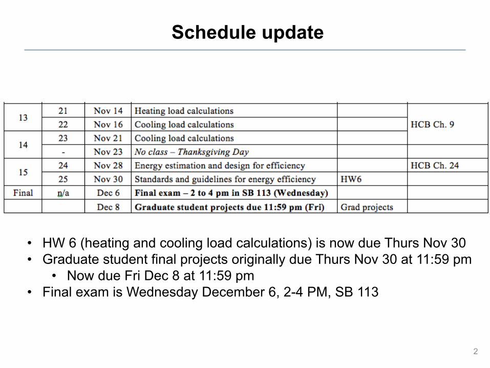
Schedule update
2
• HW 6 (heating and cooling load calculations) is now due Thurs Nov 30 • Graduate student final projects originally due Thurs Nov 30 at 11:59 pm
• Now due Fri Dec 8 at 11:59 pm • Final exam is Wednesday December 6, 2-4 PM, SB 113
Last time
• Natural ventilation and infiltration – Finish natural ventilation today
3
Natural ventilation strategies
4
Natural ventilation equations
• Airflow caused by wind only
5
!V =CvAU
V = airflow rate, m3/s
Cv = effectiveness of openings, dimensionless [Cv = ~0.5-0.6 for perpendicular winds and ~0.25-0.35 for diagonal winds]
A = free area of inlet openings, m2
U = wind speed, m/s
.
Natural ventilation equations
• Airflow caused by thermal forces (buoyancy) only
6
!V =CDA 2g HNPL −H( ) Tin −ToutTin
⎛
⎝⎜
⎞
⎠⎟
V = airflow rate, m3/s
CD = discharge coefficient for opening, dimensionless A = cross-sectional area of opening, m2
HNPL = height of neutral pressure level above reference plane, m H = height of point of opening, m Tout = outdoor air temperature, K Tin = indoor air temperature, K g = acceleration due to gravity, 9.81 m/s2
Note: If Tin < Tout, replace Tin with Tout and vice versa
.
Wind-driven natural ventilation example
• Consider the first floor of a house with two windows: one is 1 m2 in area and orientated 20 degrees away from the normal of the prevailing wind direction and another is 1.5 m2 in area on the opposite side of the room.
• If the local wind velocity is 6 m/s, determine the amount of ventilation air flowing into the room when both windows are wide open. – You can neglect infiltration due to stack effect since the indoor and
outdoor temperatures are essentially the same – Assume an opening effectiveness of 0.6
• If the volume of the house is 360 m3 (same as the last example), what is the air exchange rate?
7
When you have unequal inlet and outlet areas
8
Buoyancy-driven natural ventilation example
9
• Consider a 10 meter high atrium with openings to the outside at ground level and at roof level. The inside temperature is maintained at 25ºC and the outdoor temperature is 10ºC.
• Estimate the natural ventilation airflow rate due to stack effect pressure differences only if the area of both openings is 0.25 m2
• If the volume of the house is 360 m3 (same as the last example), what is the air exchange rate?
HEATING AND COOLING LOADS
10
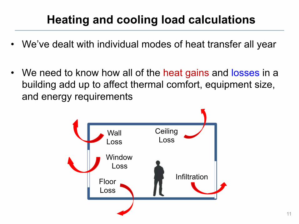
Heating and cooling load calculations
• We’ve dealt with individual modes of heat transfer all year
• We need to know how all of the heat gains and losses in a building add up to affect thermal comfort, equipment size, and energy requirements
11
Ceiling Loss
Wall Loss
Floor Loss
Window Loss
Infiltration
Heating and cooling load calculations
• When we use HVAC systems to maintain comfortable indoor conditions, we need to know what the “peak loads” for both heating and cooling are in order to design and select equipment
• The peak load tells you the maximum amount of energy that would realistically be required to supply to (or extract from) the conditioned space
• Peak loads occur at “design conditions”
• We estimate this peak load using a “heat balance” on the space in question
12
DESIGN CONDITIONS
13
Design conditions
• When sizing a system to provide heating or cooling, we need to size it for worst case conditions – Or more accurately, nearly worst case conditions
• If equipment is too small, it won’t meet the load • If equipment is too large, it will have high upfront costs and may
run at very low efficiency most of the time (remember: low efficiency at low part load ratio)
• So we choose extreme (or nearly extreme) design conditions on which to base heating and cooling load calculations – These are based on different levels of probability of
occurrence
14
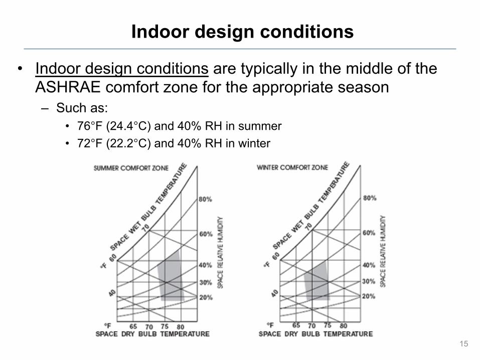
Indoor design conditions
• Indoor design conditions are typically in the middle of the ASHRAE comfort zone for the appropriate season – Such as:
• 76°F (24.4°C) and 40% RH in summer • 72°F (22.2°C) and 40% RH in winter
15
Outdoor design conditions
• Outdoor design conditions are not usually the coldest or hottest conditions ever measured, but are usually obtained from statistical summaries of long term measurements
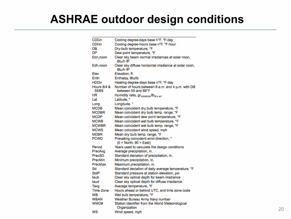
• ASHRAE has compiled decades of weather data for many cities – Available in the ASHRAE Handbook of Fundamentals Chapter 13
• ASHRAE lists the 99% and 99.6% cold temperatures for winter design conditions – Also the mean wind speed and prevailing direction
• Summer design conditions: Top 2%, 1%, or 0.4% in dry bulb temperature (DBT) – You have discretion in picking which percentile – Typically: 99% or 99.6% in either direction
• The idea is that the air temperature is colder than the 99% value for about 88 hours per year and colder than the 99.6% for about 35 hours per year
18
ASHRAE outdoor design conditions
19
ASHRAE outdoor design conditions
20
Outdoor design conditions for Chicago?
21
The winter 99% dry bulb temperature is 3.7°F at O’Hare and the 99.6% dry bulb temperature is -1.5°F
The summer 1% dry bulb temperature is 88.7°F at O’Hare and the 0.4% dry bulb temperature is 91.4°F
City of Chicago requirements for design conditions
• The City of Chicago Building code has required design conditions that differ slightly from ASHRAE – Section 18-13-302.1
temperature is 72°F for heating and 75°F for cooling
• Local codes supersede ASHRAE
22
What is this?
A note on “degree-days” • The energy use of a building is directly related to the temperature
difference between outdoor and indoor air • Heating equipment is assumed to run when the outdoor
temperature drops below the “balance temperature” – The balance temperature is the outdoor air temperature at which the
internal heat gains balance the heat loss to the outside – This is less than the interior temperature set point – The amount of time that this situation occurs is described by:
• Heating Degree Days
• Cooling equipment is assumed to run when the outdoor temperature is above the balance temperature – The balance temperature might not be the same for heating and cooling
because the interior temperature, interior heat gain, and building heat loss usually differ in summer and winter
– The amount of time that this situation occurs is described by: • Cooling Degree Days
23
Selecting a base temperature
• HDD65F and CDD65F are common HDD/CDD levels that are used regularly in industry (both with a base of 65°F)
24
HDD = [Tbal −Tout (t)]dt∫ when Tout <TbalCDD = [Tout (t)−Tbal ]dt∫ when Tout >Tbal
HDD65F maps
25
HDD65F maps
26
Chicago: HDD65 = 6280 °F-days
CDD65F maps
27
CDD65F maps
28
Chicago: CDD65 = 1115 °F-days
LOAD CALCULATION PROCEDURES
29
Heat balance
• For either heating or cooling loads at design conditions, we can calculate a “heat balance” on a building/space/zone in question
U = overall heat transfer coefficient for walls, roof, ceiling, floor, glazing, etc. [BTU/hr·ft2·°F] or [W/m2K] A = area of walls, roof, ceiling, floor, glazing, etc. [ft2] or [m2] Tin = indoor air design temperature [°F] or [K] Tout = outdoor air design temperature [°F] or [K] VOA = volumetric flow rate of outdoor air due to air exchange [ft3/hr] or [m3/s] ρOA = density of outdoor air [lb/ft3] or [kg/m3] Cp,air = specific heat capacity of air [BTU/lb·°F] or [J/kg]
.
Total heat transmission coefficient: Envelope + air exchange
• We can also lump conduction and air exchange together to define a total building heat transfer coefficient, Ktotal:
Typical heat gains include: • Solar gains through windows (always positive, or 0 at night) • Heat gains from occupants, lights, and equipment (internal
gains) – Motors, copiers, computers, appliances, etc. – We need to know their scheduling (when they are off and on) as well
as their magnitude
• Internal heat gains are heat sources on the inside of the building – These are all always positive (+), meaning they always add heat to
the interior of the building – Internal heat gains can affect both heating and cooling loads
34
Qgains =Qsolar +Qlight +Qequip +Qocc
Heat gains from lighting
• Lights are often a major internal heat load component – This is changing as lighting efficiency increases
• Lights contribute to heat gain through convection and radiation – Function of total wattage and how much they are used
35
Heat gains from lighting
• You can also use typical “lighting power densities” for different kinds of spaces
36
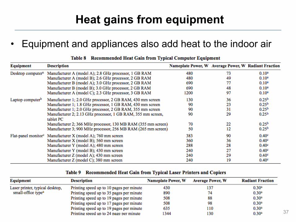
Heat gains from equipment
• Equipment and appliances also add heat to the indoor air
37
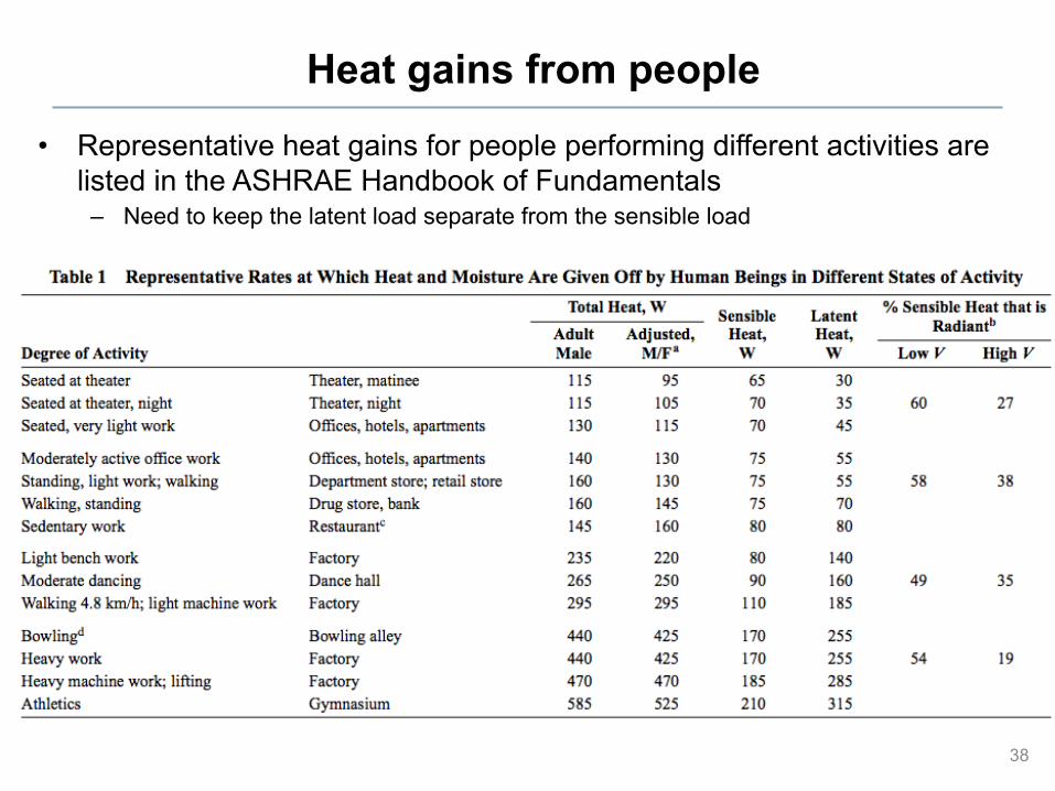
Heat gains from people
• Representative heat gains for people performing different activities are listed in the ASHRAE Handbook of Fundamentals
– Need to keep the latent load separate from the sensible load
38
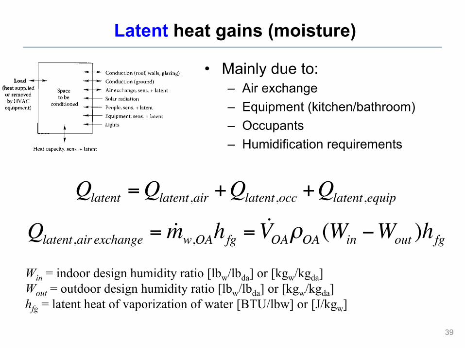
Latent heat gains (moisture)
• Mainly due to: – Air exchange – Equipment (kitchen/bathroom) – Occupants – Humidification requirements
39
Qlatent =Qlatent,air +Qlatent,occ +Qlatent,equip
Qlatent,air exchange = !mw,OAhfg = !VOAρOA (Win −Wout )hfgWin = indoor design humidity ratio [lbw/lbda] or [kgw/kgda] Wout = outdoor design humidity ratio [lbw/lbda] or [kgw/kgda] hfg = latent heat of vaporization of water [BTU/lbw] or [J/kgw]
Heating load calculation procedures
40
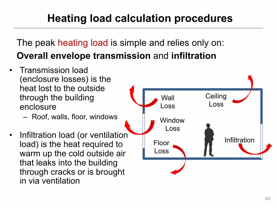
The peak heating load is simple and relies only on: Overall envelope transmission and infiltration
• Transmission load (enclosure losses) is the heat lost to the outside through the building enclosure – Roof, walls, floor, windows
• Infiltration load (or ventilation load) is the heat required to warm up the cold outside air that leaks into the building through cracks or is brought in via ventilation
Ceiling Loss
Wall Loss
Floor Loss
Window Loss
Infiltration
Heating load calculation procedures
• Heating load calculations are based on instantaneous heat losses – The maximum heating load should occur before sunrise on the
coldest days of the year
• Therefore, we assume that: – All heating losses are instantaneous heating loads
• We ignore any effects of thermal storage – Solar heat gains and internal loads are usually not taken into account
except for those internal loads that continuously release heat inside the conditioned space during the whole heating season
– The only latent load (if any) is that which is required to evaporate liquid water for maintaining adequate humidity
41
Heating load calculation procedures
1. Define your design conditions (Tin and Tout) 2. Define the building envelope that separates conditioned
(i.e., heated) space from unconditioned space 3. Determine the envelope and air exchange heat
transmission coefficient (Ktotal) 4. Determine any indoor heat sources present at the time of
the peak load, e.g., people, equipment, lights, etc. (Qgains) 5. Calculate the instantaneous heat load using:
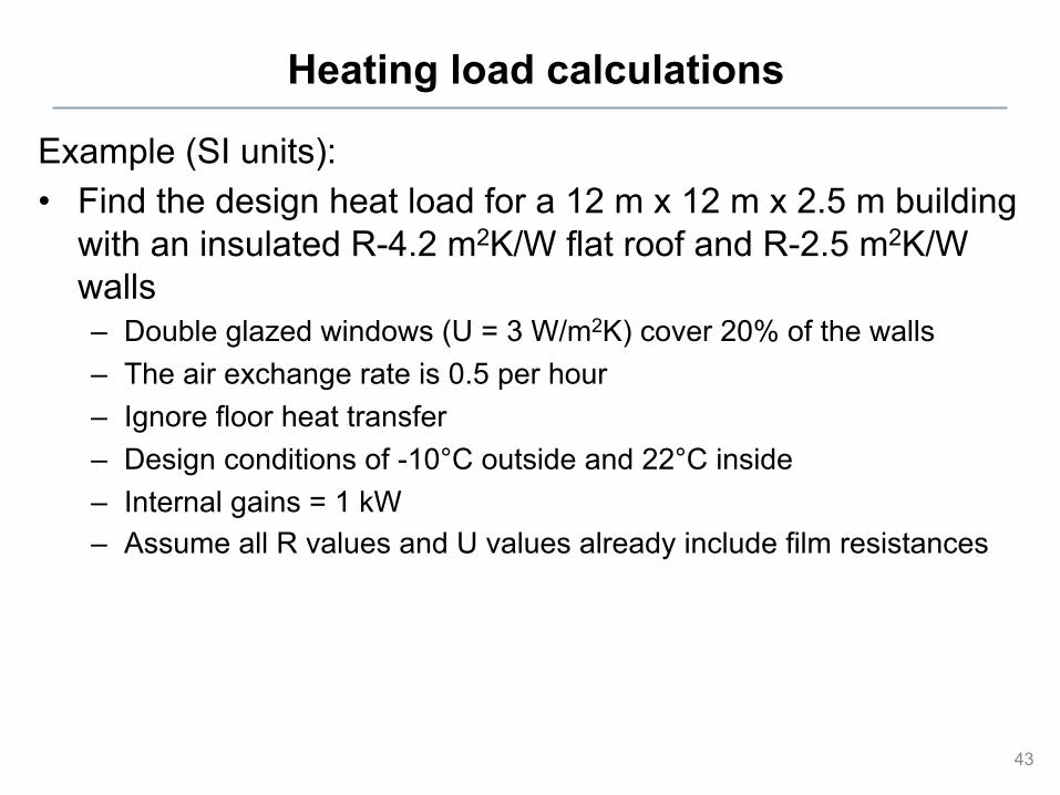
Example (SI units): • Find the design heat load for a 12 m x 12 m x 2.5 m building
with an insulated R-4.2 m2K/W flat roof and R-2.5 m2K/W walls – Double glazed windows (U = 3 W/m2K) cover 20% of the walls – The air exchange rate is 0.5 per hour – Ignore floor heat transfer – Design conditions of -10°C outside and 22°C inside – Internal gains = 1 kW – Assume all R values and U values already include film resistances
43
Heating load calculations (single zone – IP units)
Calculate the peak heating load for the office room shown here (at 99.6%):
44
Location: Atlanta, GA, 2nd floor of a two-story building, Enclosure: 2 vertical exterior exposures and a flat roof above Area: 130 ft2
Ceiling height: 9 ft Floor: Carpeted 5 inch concrete slab on metal deck above conditioned space Roof: Flat metal deck with rigid closed cell polyisocyanurate foam insulation (R=30 hr-ft2-°F/BTU) Spandrel wall: Bronze tinted glass, opaque, backed with air space and rigid fiberglass insulation. Total U-value of 0.077 BTU/hr-ft2-°F Insulated brick wall: Brick with continuous exterior insulation and interior fiberglass batt insulation. Total U = 0.08 BTU/hr-ft2-°F). Infiltration: 1 air change per hour during peak heating Window U values: Double glazed ¼” bronze tinted with 1/2” air space. Total U = 0.56 BTU/hr-ft2-°F. Occupancy: None during peak heating Lighting: None during peak heating Indoor design conditions: 72°F for heating
Heating load calculations (single zone – IP units)
45
Selecting equipment
• Once you know your design heating load, you can select equipment