Information Technology and Electrical Engineering - Devices and Systems, Materials and Technologies for the Future Faculty of Electrical Engineering and Information Technology Startseite / Index: http://www.db-thueringen.de/servlets/DocumentServlet?id=14089 54. IWK Internationales Wissenschaftliches Kolloquium International Scientific Colloquium 07 - 10 September 2009 PROCEEDINGS
Transcript
Information Technology and Electrical Engineering - Devices and Systems, Materials and Technologies for the Future
Faculty of Electrical Engineering and Information Technology
Impressum Herausgeber: Der Rektor der Technischen Universität llmenau Univ.-Prof. Dr. rer. nat. habil. Dr. h. c. Prof. h. c.
Peter Scharff Redaktion: Referat Marketing Andrea Schneider Fakultät für Elektrotechnik und Informationstechnik Univ.-Prof. Dr.-Ing. Frank Berger Redaktionsschluss: 17. August 2009 Technische Realisierung (USB-Flash-Ausgabe): Institut für Medientechnik an der TU Ilmenau Dipl.-Ing. Christian Weigel Dipl.-Ing. Helge Drumm Technische Realisierung (Online-Ausgabe): Universitätsbibliothek Ilmenau Postfach 10 05 65 98684 Ilmenau
ABSTRACT Versions of creation of the multiple-beam passive systems of radiovision of a millimetre-wave are observed. Geometrical performances and radiation characteristics of the multiple-beam systems on the basis of the phased arrays and the systems representing a grid of receiving units in a focal plain of the aerial are calculated. Calculation of a slowing spherical microwave lens with disposed in a focal plain or apart from a focal plain of a grid of radiation sources is carried out. Geometrical performances and radiation characteristics of the axisymmetrical Cassegrainian aerial with one radiation source and with a grid of radiation sources are calculated. The comparative analysis of the multiple-beam systems is carried out.
Index Terms - the multiple-beam system of radiovision, the radiometer, the phased array, microwave lens, the Cassegrainian aerial, the pyramidal horn, the open extremity of the waveguide, the log-periodic aerial, the directional diagramme.
1. INTRODUCTION
The primal problem of passive systems of radiovision of a millimetre-wave is a creation of a radio thermal image of some field of space. In systems with one-radial receivers at the consecutive review it is possible to gain a pattern which will adequately not mirror an object state for the given time span. Systems with the multiple-beam receivers allow to see in each instant all researched field of space bodily.
Two are possible conceptually different version of the multiple-beam systems: systems on the basis of the phased arrays (drawing 1), filling some aperture, and the systems representing a grid of receiving units in a focal plain of the aerial (drawing 2). Combinations of these versions are possible also.
Drawing 1 Multiple-beam system on the basis of the phased arrays
Drawing 2 Multiple-beam system with a grid of receiving units in a focal plain
The multiple-unit receiving grid in a focal plain of
the aerial allows to dilate essentially its field of view, to increase a total responsivity, to accelerate process of imaging of distributed sources, to reduce agency of an aerosphere [1].
The principle of operation of such systems is grounded on focalizing of a characteristic thermal radio radiation of the object in a focal plain of receiving units. A base site of each receiving unit is the aerial, the geometry and which construction are adapted for reception of raying in the field of operational frequencies of system of radiovision.
Focalizing of a characteristic thermal radio radiation can implement by means of one-mirror, two-mirror or microwave lenses.
Let's observe the antenna system figured in drawing 1. It consists from the linear phase-aerial of a grid and two masts on which this array is displaced in a vertical plane. At the expense of array application the given construction of the aerial meets the requirement high resolving power. However at the expense of the consecutive review of space and application of the one-radial receiver at the review we gain a pattern which will adequately not mirror an object state for the given time span.
Let's carry out probe of behaviour of the directional diagramme of an array at scanning. Array parametres are resulted in table 1.
Table 1 Parameters the grid phase-aerial
The parametre name Parametre value λ = 8 mm λ = 3 mm
Frequency f, GHz 37,5 100 Scan sector θss, град 80 80 Ширина ДН ∆θ, grad 0,3 0,3 Distance between emitters on shaft Х d, mm 4,8 1,8 Number of emitters on shaft Х m, pieces 267 267 Length of grid L, m 1,3 0,48 Directivity factor D 1811
(32,58dB) 1612
(32,01dB) Уро Level of side lobes δ, dB − 13,5 − 13,5 The waveguide sizes a× b, mm 7,2× 3,6 2,4× 1,2
As displays calculation, at wavelength decrease the directivity factor drops.
In drawing 3 the directional diagramme of the array made of the open ends of waveguides, with uniform peak allocation is presented at a wavelength of 8 mm.
In drawing 4 the directional diagramme of an array with non-uniform peak allocation of a type “cosine on a dado” is presented at a wavelength of 8 mm.
Drawing 3 Directional diagramme with uniform peak
allocation at λ = 8 mm
Drawing 4 Directional diagramme with non-uniform
peak allocation at λ = 8 mm
Apparently from matching of drawings 3 and 4, nonuniform distribution application allows to diminish level of side lobes.
At wavelength decrease as has displayed calculation, there is a directivity factor falling.
In drawing 5 the directional diagramme with uniform peak allocation is resulted at a wavelength of 8 mm for a slope of the main beam on 40 grades. The directional diagramme with non-uniform peak allocation of a type “cosine on a dado” for the same slope is resulted in drawing 6.
Drawing 5 Directional diagramme with uniform peak allocation and at a beam skew on 40 grades
Drawing 6 Directional diagramme with non-uniform peak allocation and at a beam skew on 40 grades
Comparing drawings 3 - 6 it is possible to draw
following conclusions: - At magnification of a slope of a beam level of
side lobes is increased and the directivity factor is diminished;
- The greatest directivity factor grids with uniform drive possess;
- Application of a nonuniform distribution of amplitudes allows to depress level of side raying by loss in value of directivity factor.
The system of radiovision on the basis of the grid calculated by the phase-aerial (drawing 1) ensures high resolving power thanks to narrow width of the main beam of the directional diagramme (0,3 grad). However such systems because of the consecutive review of space do not allow to gain all researched field of space in front of the aerial bodily. At the multiple-beam building of a system on the basis of the linear phase-aerial of a grid rate of the review, but insufficient for obtaining of the radio map of the object in a real time is ensured major in comparison with one-radial systems. The high speed of the review of space is ensured in the multiple-beam systems with the two-dimensional phase-aerial a grid. However such system will be very expensive.
At radiovision system development it is necessary to start with the compromise between cost of system and its performances. Thus, the radiovision system should meet the requirement high performances at the minimum cost. To such demand fulfil systems of radiovision with a grid of receiving units in a focal plain of the aerial.
3. CALCULATION OF THE MULTIPLE-BEAM MICROWAVE LENSES
The multiple-beam directional diagramme in microwave lenses can be executed as follows: seating of a negative mould of receiving units in a focal plain (drawing 7) and seating of a negative mould of receiving units between focal point and lens aperture (drawing 8).
Drawing 7 Microwave lens with the negative mould of receiving units disposed in a focal plain
Drawing 8 Microwave lens with the negative mould of receiving units disposed between focal point and
aperture of a lens
Parametres of a lens and units of a receiving negative mould are resulted in table 2. Table 2 Parameters of a microwave lens and units of a receiving negative mould
The name Value Lens type Slowing dielectric lens Lens material Polysterene Index of refraction of lens n 1,6 Diameter of lens D , sm 50 Type of a unit of a receiving negative mould
The open extremity of the waveguide,
The log-periodic aerial The worker is long waves λ , mm
8 3
Waveguide sizes ba × , mm
7,2× 3,6 2,4× 1,2
Distance between units of receiving negative mould d , mm
4,8 1,8
Let's observe a microwave lens figured in drawing
7. We will calculate the greatest possible quantity of the receiving units disposed in a focal plain.
At offset of the radiation source from focal point in a perpendicular direction to a lens axis there are unbalanced distortions of a phase in aperture. At small offset the length of optical path from the radiation source before lens aperture will vary in the beginning linearly along aperture. It will lead only to a deflexion of a principal maxima of the directional diagramme on some corner α concerning a direction which it received when the radiation source was precisely in focal point. The directional diagramme form thus practically is not distorted. In lenses with special correction of distortion at scanning (aplanatic magnifying lenss), which form of a surface the considerable offset of the radiation source defined by the given scan sector [2] is specially calculated, admitted.
In not aplanatic magnifying lenss the surface form is calculated only from a requirement of focusing and offset of the radiation source from focal point on distance from a shaft above the admissible will lead to a directional diagramme deformation and consequently it is necessary to limit such offset to the appropriate tolerance.
The calculated geometrical performances of a microwave lens and lattice parametres of receiving units are resulted in table 3. Table 3 Geometrical performances of a microwave lens and lattice parametres of receiving units
The name Value λ1 = 8mm λ2 = 3mm
Diameter of lens D , m 0,5 0,5 Width of the directional diagramme of a microwave lens
)( ϕθ ∆∆ , grad 0,917 0,344
Focal distance of lens f , m 0,6 0,6 Width of lens 0t , m 0,075 0,075 Corner of aperture of lens 0θ , rad (grad)
0,355 (20,33)
0,355 (20,33)
The permissible deviation of the radiation source from focal point
maxa , m 0,014 0,0054
Maxima of directional diagramme maxα , rad (grad)
0,024 (1,38)
0,009 (0,52)
Length of grid L, m ≤ 0,029 ≤ 0,011 Quantity of receiving units N, pieces 6 6
Apparently from table 3, with wavelength decrease at equal diameter of a lens are diminished width of the directional diagramme of a microwave lens, the permissible deviation of the radiation source from focal point and length of a grid of radiation sources is maximum. However thus there is stationary values a lens focal distance, width of a lens, a corner of aperture of a lens and quantity of receiving units (radiation sources). The last fact indicates a capability of making of the multiple-beam microwave lens of 3 millimetre-waves of waves with the same quantity of receiving units, as well as for a microwave lens 8 millimetre-waves, but with smaller width of the directional diagramme.
The multiple-unit negative mould of receiving units can be made of the open ends of waveguides or log-periodic aerials. Thus special differences in geometrical performances, such as the length of a grid and distance from focal point to a lens, and also in radiation characteristics is not observed. The negative mould of receiving units from log-periodic aerials allows to ensure major broadbandness, than the negative mould of receiving units from the open ends
of waveguides and can be made on thin films of Al oxide width 100 microns.
The directional diagramme of a microwave lens for the calculated quantity of receiving units from the open ends of waveguides or log-periodic aerials is presented in drawing 9.
Apparently from drawing 9, fluence of an electromagnetic wave dropping on a lens to aperture edges is diminished in comparison with centre. It happens at the expense of a modification of parametres of a lens, such as width of a lens and an aperture corner, at driving from lens centre to its edges.
The relation of width of the directional diagramme of a microwave lens to diameter of a lens is presented in drawing 10.
а)
б)
Drawing 9 Directional diagramme of a microwave lens with receiving units from the open ends of
waveguides or log-periodic aerials: а) Е, Н - Plain at λ = 8 mm; б) Е, Н - Plain at λ = 3 mm
Drawing 10 Relation of width of the directional diagramme of a microwave lens to diameter of a lens
From drawing 10 it is visible, that for diameters of
a lens of 550 mm (λ = 8 mm) and 207 mm (λ = 3 mm) are gained equal width of the directional diagramme of a microwave lens 0,83 grad. It allows to speak about a capability of making of microwave lenses for different wave bands with equal directional diagrammes, but with different dimensional performances.
Let's observe a microwave lens figured in drawing 8. We will calculate distance f1 on which it is necessary to dispose a negative mould of receiving units and quantity of receiving units N depending on distance f1.
Calculation of length of grid L and distances f1 for various quantity of receiving units is resulted in table 4.
The relation of distance on which the negative mould of receiving units places, from quantity of receiving units from the open ends of waveguides and log-periodic aerials is figured in drawing 11. Table 4 Calculation of length of grid L and distances f1
The name Value
N = 4 N = 8 N = 16 λ1 = 8
mm λ2 = 3
mm λ1 = 8
mm λ2 = 3
mm λ1 = 8
mm λ2 = 3
mm Distance between radiation sources, d, mm
4,8 1,8 4,8 1,8 4,8 1,8
Length of grid
dNL ⋅= , mm
19,2 7,2 38,4 14,4 76,8 28,8
Distance )0(21 θctgLf ⋅= ,
mm 27,1 10,2 54,3 20,4 108,6 40,7
Drawing 11 Relation of distance f1 from quantity of
receiving units N
Apparently from drawing 11, the distance on which the negative mould of receiving units places, for a wavelength of 8 mm lays in limits from 27 mm to 217 mm and in limits from 10 mm to 81 mm for a wavelength of 3 mm at quantity of receiving units from 4 to 32.
In the second mode of implementation of the multiple-beam directional diagramme at the expense of a great many of beams it is possible to gain higher resolving power of system of radiovision, than in the first mode. Thus the microwave lens sizes, such as diameter of a lens, width of a lens and a lens focal distance remain equal.
Resolving power in the first mode is restricted as much as possible by a permissible deviation of the radiation source from focal point. In the second mode resolving power depends on distance from focal point to a negative mould of receiving units: the more this distance, the is more quantity of receiving units, so and above resolving power. Thus, from the given resolving power depending on a field of application of system of radiovision, the mode of implementation of the multiple-beam directional diagramme depends also.
4. CALCULATION OF THE MULTIPLE-BEAM CASSEGRAINIAN AERIALS
The multiple-beam Cassegrainian aerial is resulted in drawing 12.
In drawing 13 grids of radiation sources from the open ends of waveguides and log-periodic aerials are figured.
Drawing 12 Axisymmetrical Cassegrainian aerial
рb
ра ва
вb
Drawing 13 Grid of radiation sources from the open ends of waveguides (a) and log-periodic aerials (b)
Initial data for calculation and the calculated
parametres are resulted in table 5.
Table 5 Cassegrainian aerial Parameters The parametre name Parametre value
Wavelengthλ, mm 3 Diameter of major mirror бD , mm
300 Focal distance of major mirror бf , mm 120
Diameter of small mirror мD , mm 50 Short-range focal distance of small mirror м2f , mm 19,86 Long-distance focal distance of small mirror м1f , mm 76,62
Table 5 Radiation source type The pyramidal
horn, The open
extremity of the waveguide,
The log-periodic aerial
The sizes of horn рр ba × , mm 16× 10,5 Waveguide sizes вв ba × , mm 2,4× 1,2 The sizes of the log-periodic aerial
α, grad 65 β, grad 30
оптψ , grad 79 τ 0,5 σ 0,7 R1, mm 3,778 r1, mm 2,644
Half of angle of aperture of major mirror 0ψ , rad (grad) 1,117 (64)
Eccentricity of small mirror e 1,23 Half of angle of view on small mirror 0ϕ , rad (grad) 0,13 (7,45)
Antenna pattern width on half power 5,0θ∆ , grad 0,7
Apparently from table 5, the observed
axisymmetrical Cassegrainian aerial of 3 millimetre-waves of lengths of waves has diameter of a major mirror equal 30 sm, a corner of aperture of a major mirror of equal 128 grades, diameter of a small mirror equal 5 sm, an eccentricity of a small mirror equal 1,23, an angle of view on a small mirror of equal 15 grades. At such geometrical sizes the directional diagramme width on half power is equal 0,7 grades. High resolving power of system of radiovision is thus ensured.
The directional diagramme of the axisymmetrical Cassegrainian aerial without shading and taking into account shading by a small mirror for plain Е with the radiation source in the form of the log-periodic aerial is figured in drawing 14.
Drawing 14 Directional diagramme of the unshaded
and shaded Cassegrainian aerial
Apparently from drawing 14, at shading by a small mirror level of side lobes is increased. The directional diagramme width at shading by a small mirror is increased only at application in the capacity of the radiation source of the open end of the waveguide. Taking into account this fact, by selection of a type of the radiation source the preference should be returned log-periodic aerials.
The calculated values of a coefficient of utilisation of a surface and directivity factor of the axisymmetrical Cassegrainian aerial for a various type of the radiation source are resulted in table 6.
Apparently from table 6, the greatest values of a coefficient of utilisation of a surface and directivity factor the Cassegrainian aerial with the radiation source in the form of the pyramidal horn possesses. It speaks the various sizes of radiation sources: aperture of the pyramidal horn is more than aperture of the open end of the waveguide and the log-periodic aerial. For magnification of a coefficient of utilisation of a surface and directivity factor it is possible to use a grid of such radiation sources instead of one radiation source.
Table 6 Calculation of a coefficient of utilisation of a surface and directivity factor
Radiation source type
Parametre A coefficient of utilisation
of surface Аν , time (dB)
Directivity factor 0D , time (dB)
The pyramidal horn 0,597 (2,242) 58890
(47,701) The open extremity of the waveguide
0,014 (18,4) 1426 (31,542)
The log-periodic aerial 0,031 (15,114) 3040 (34,829)
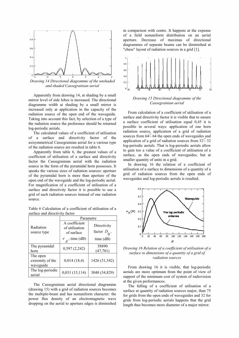
The Cassegrainian aerial directional diagramme
(drawing 15) with a grid of radiation sources becomes the multiple-beam and has nonuniform character: the power flux density of an electromagnetic wave dropping on the aerial to aperture edges is diminished
in comparison with centre. It happens at the expense of a field nonuniform distribution on an aerial aperture. Decrease of maximas of directional diagrammes of separate beams can be diminished at "chess" layout of radiation sources in a grid [1].
Drawing 15 Directional diagramme of the Cassegrainian aerial
From calculation of a coefficient of utilisation of a
surface and directivity factor it is visible that to ensure a surface coefficient of utilisation equal 0,45 it is possible in several ways: application of one horn radiation source, application of a grid of radiation sources from 64× 64 the open ends of waveguides and application of a grid of radiation sources from 32× 32 log-periodic aerials. That is log-periodic aerials allow to gain too a value of a coefficient of utilisation of a surface, as the open ends of waveguides, but at smaller quantity of units in a grid.
In drawing 16 the relation of a coefficient of utilisation of a surface to dimensions of a quantity of a grid of radiation sources from the open ends of waveguides and log-periodic aerials is resulted.
Drawing 16 Relation of a coefficient of utilisation of a
surface to dimensions of a quantity of a grid of radiation sources
From drawing 16 it is visible, that log-periodic
aerials are more optimum from the point of view of support of the minimum cost of system of radiovision at the given performances.
The falling of a coefficient of utilisation of a surface at quantity of radiation sources major, than 75 for grids from the open ends of waveguides and 32 for grids from log-periodic aerials happens that the grid length thus becomes more diameter of a major mirror.
At application of a grid of radiation sources limitation on quantity of units of a grid is superimposed. It depends on length of a grid which is determined as much as possible by a radiation source permissible deviation in a perpendicular direction to a shaft. The radiation source removal results not only in a directional diagramme deflexion aside, opposite to radiation source offset, but also to its distortion owing to violation of the linear law of a phase change of the field in aperture. It leads to the extension of a principal lobe and magnification of level of side lobes that guides to gain decrease. The more finely a mirror, the there will be distortions at the same angular displacement of the radiation source less, that is those on a major corner can deflect the directional diagramme, saving, basically, its form. The higher level concerns to deficiencies of aerials with the carried out radiation source a distributing frame of polarisation leading to additional handicapes also.
In reflector aerials with special correction of distortion at scanning (aplanatic aerials) which form of a surface is specially calculated, admitted the considerable offset of the radiation source defined by the given scan sector. In not aplanatic reflector aerials the surface form is calculated only from a requirement of focusing and offset of the radiation source from focal point on distance from a shaft above the admissible will lead to a directional diagramme deformation and consequently it is necessary to limit such offset to the appropriate tolerance.
Outcomes of calculation of quantity of units of a grid for a various type of radiation sources are resulted in table 7.
Table 7 Calculation of quantity of units of a grid
The parametre name Parametre value
The open extremity of the
waveguide
The log-periodic
aerial The radiation source permissible deviation h, mm
117 117
Distance between radiation sources
yx dd × , mm 3 × 1,8 9 × 9
Quantity of units of grid yx NN × , pieces
38 × 64 12 × 12
Apparently from table 7, the maximum quantity of
units of a grid from the open ends of waveguides at which there is no the considerable distortion of the directional diagramme, is equal 38 on shaft Х and 64 on a Y-axis. The same quantity of units of a grid from log-periodic aerials equally 12 both on shaft Х and on a Y-axis.
5. CONCLUSION
The radiovision system on the basis ensures with the grid phase-aerial high resolving power thanks to narrow width of the main beam of the directional diagramme (0,3 grad). However such systems because of the consecutive review of space do not allow to gain all researched field of space in front of the aerial bodily. At the multiple-beam building of a system on the basis of the linear phase-aerial of a grid rate of the review, but insufficient for obtaining of the radio map of the object in a real time is ensured major in comparison with one-radial systems. The high speed of the review of space is ensured in the multiple-beam systems with the two-dimensional phase-aerial a grid. However such system will be very expensive.
At radiovision system development it is necessary to start with the compromise between cost of system and its performances. Thus, the radiovision system should meet the requirement high performances at the minimum cost. To such demand fulfil systems of radiovision with a grid of receiving units in a focal plain of the aerial.
The principle of operation of such systems is grounded on focalizing of a characteristic thermal radio radiation of the object in a focal plain of receiving units. A base site of each receiving unit is the aerial, the geometry and which construction are adapted for reception of raying in the field of operational frequencies of system of radiovision.
Focalizing of a characteristic thermal radio radiation can implement by means of one-mirror, two-mirror or microwave lenses.
Common faults of one-reflector aerials are inconvenience of a conclusion of high-frequency energy from the radiation source, rather major longitudinal sizes and a restricted scan sector at offset of the radiation source from focal point in a focal plain.
The main disadvantage of the Cassegrainian aerial - the shading of aperture created by a small mirror. If not to receive special standards on blanketing effect elimination, actual allocation of amplitudes of the field in aperture will have a fall at centre that reduces aerial directivity factor. This decrease by that more than more relative square of a small mirror.
Advantage of microwave lenses in front of reflector aerials consists that at manufacture of their surface the smaller exactitude necessary for making of the demanded directional diagramme is required. Besides, as the radiation source of a microwave lens does not screen aerial raying, the construction of its bracing can be the most various. The phase errors linked to a different phase of arrival of waves from a stimulus source, located in aerial focal point, to any point of an aerial aperture and distorting the directional diagramme, for the reflector aerial are maximum at aperture centre, and for a lens - on the brink, and, therefore, affect much less.
Great volume and mass of a lens, loss concern to deficiencies of microwave lenses in a material of a lens and on reflecting from its surfaces, higher cost in comparison with reflector aerials.
6. REFERENCES
[1] Majorova E.K., Khaikin V. B. A multiple-unit focal grid in radiotelescope focal point//the Bulletin of a special astrophysical observatory - 2000. - № 50. - With. 91 - 103. [2] Shuk M.S., Molochkov J.B. projection of the lens, scanning, all-band antennas and feeder arrangements. - М: Energy, 1973. - 440 with.