Calculation of buoyancy safety and safety against hydraulic failure GGU-UPLIFT VERSION 6 Last revision: July 2015 Copyright: Prof. Dr. Johann Buß Technical implementation and sales: Civilserve GmbH, Steinfeld
Transcript
Calculation of buoyancy safety and safety against hydraulic failure
GGU-UPLIFT
VERSION 6
Last revision: July 2015 Copyright: Prof. Dr. Johann Buß Technical implementation and sales: Civilserve GmbH, Steinfeld
2 Licence protection and installation .................................................................................... 4
3 Language selection............................................................................................................... 5
4 Starting the program........................................................................................................... 5
5 Theoretical principles .......................................................................................................... 6 5.1 La Place differential equation .......................................................................................... 6 5.2 Buoyancy.......................................................................................................................... 6
5.2.1 Buoyancy safety using global safety factors............................................................ 6 5.2.2 Utilisation factor (buoyancy) using partial safety factors ........................................ 7
5.3 Hydraulic failure .............................................................................................................. 8 5.3.1 Hydraulic failure safety using global safety factors................................................. 8 5.3.2 Utilisation factor (hydraulic failure) using partial safety factors ............................. 8 5.3.3 Analysis of hydraulic heave after Aulbach/Ziegler ................................................. 9
6 Worked examples............................................................................................................... 10 6.1 Example 1: Analysis using partial factors ...................................................................... 10
6.1.1 Description of the system (Ex. 1) .......................................................................... 10 6.1.2 Create new data set (Ex. 1) .................................................................................... 11 6.1.3 System data input (Ex. 1)....................................................................................... 12 6.1.4 Edit soils (Ex. 1) .................................................................................................... 12 6.1.5 Analyse system (Ex. 1) .......................................................................................... 13 6.1.6 Layout of the output sheet (Ex. 1) ......................................................................... 14
6.2 Example 2: Optimising the system................................................................................. 15 6.2.1 Create new data set (Ex. 2) .................................................................................... 15 6.2.2 System data input (Ex. 2)....................................................................................... 16 6.2.3 Edit soils (Ex. 2) .................................................................................................... 17 6.2.4 Analyse and optimize system (Ex. 2) .................................................................... 17
7 Description of menu items................................................................................................. 19 7.1 File menu........................................................................................................................ 19
7.1.1 "New" menu item................................................................................................... 19 7.1.2 "Load" menu item.................................................................................................. 19 7.1.3 "Save" menu item .................................................................................................. 20 7.1.4 "Save as" menu item .............................................................................................. 20 7.1.5 "Printer preferences" menu item............................................................................ 20 7.1.6 "Print and export" menu item ................................................................................ 20 7.1.7 "Batch print" menu item ........................................................................................ 22 7.1.8 "Exit" menu item.................................................................................................... 22 7.1.9 "1, 2, 3, 4" menu items........................................................................................... 22
7.2 Edit menu ....................................................................................................................... 23 7.2.1 "Project identification" menu item......................................................................... 23 7.2.2 "Analysis options" menu item................................................................................ 23 7.2.3 "System parameters" menu item ............................................................................ 23
7.2.3.1 Input for 'classical' analysis ........................................................................... 23 7.2.3.2 Input for analysis of hydraulic heave after Aulbach/Ziegler......................... 24
GGU-UPLIFT User Manual Page 2 of 41 July 2015
7.2.4 "Soils" menu item .................................................................................................. 25 7.2.5 "Partial safety factors" menu item ......................................................................... 26
7.3 System menu .................................................................................................................. 27 7.3.1 "Analyse" menu item ............................................................................................. 27 7.3.2 "Optimise" menu item............................................................................................ 28
7.4 Output preferences menu ............................................................................................... 29 7.4.1 "General legend" menu item.................................................................................. 29 7.4.2 "System presentation" menu item.......................................................................... 30 7.4.3 "Buoyancy safety legend" menu item.................................................................... 31 7.4.4 "Hydraulic failure safety legend" menu item......................................................... 31 7.4.5 "Soil properties legend" menu item ....................................................................... 32 7.4.6 "Page size and margins" menu item....................................................................... 33 7.4.7 "Move objects" menu item..................................................................................... 33
7.5 Graphics preferences menu ............................................................................................ 34 7.5.1 "Refresh and zoom" menu item ............................................................................. 34 7.5.2 "Zoom info" menu item ......................................................................................... 34 7.5.3 "Legend font selection" menu item........................................................................ 34 7.5.4 "Margins and borders" menu item ......................................................................... 34 7.5.5 "Pen colour and width" menu item ........................................................................ 35 7.5.6 "Mini-CAD toolbar" menu item ............................................................................ 35 7.5.7 "Toolbar preferences" menu item .......................................................................... 35 7.5.8 "Load graphics preferences" menu item ................................................................ 36 7.5.9 "Save graphics preferences" menu item................................................................. 36
7.6 ? menu ............................................................................................................................ 37 7.6.1 "Copyright" menu item.......................................................................................... 37 7.6.2 "Help" menu item .................................................................................................. 37 7.6.3 "GGU on the web" menu item............................................................................... 37 7.6.4 "GGU support" menu item..................................................................................... 37 7.6.5 "What’s new ?" menu item .................................................................................... 37 7.6.6 "Language preferences" menu item ....................................................................... 37
8 Tips and tricks.................................................................................................................... 38 8.1 Keyboard and mouse...................................................................................................... 38 8.2 Function keys ................................................................................................................. 38 8.3 "Copy/print area" icon.................................................................................................... 39
The GGU-UPLIFT program allows analysis of buoyancy safety and safety against hydraulic failure. In addition, the hydraulic heave safety can be analysed using the Aulbach/Ziegler method (Aulbach, Benjamin; Ziegler, Martin: Simplified design of excavation support and shafts for safety against hydraulic heave (Einfache Bemessung von Baugruben und Schächten im Hinblick auf die Sicherheit gegen hydraulischen Grundbruch). In: Geomechnics and Tunnelling 6 (2013), No. 4, p. 362-374, ISSN 1865-7362).
Data input is in accordance with conventional WINDOWS operations and can therefore be learned almost entirely without the use of a manual. Graphic output supports the true-type fonts supplied with WINDOWS, so that excellent layout is guaranteed. Colour output and any graphics (e.g. files in formats BMP, JPG, PSP, TIF, etc.) are supported. DXF files can also be imported by means of the integrated Mini-CAD module (see the "Mini-CAD" manual).
The program has been thoroughly tested. No faults have been found. Nevertheless, liability for completeness and correctness of the program and the manual, and for any damage resulting from incompleteness or incorrectness, cannot be accepted.
2 Licence protection and installation
In order to guarantee a high degree of quality, a hardware-based copy protection system is used for the GGU-UPLIFT program.
The GGU software protected by the CodeMeter copy protection system is only available in conjunction with the CodeMeter stick copy protection component (hardware for connection to the PC, "CM stick"). Because of the way the system is configured, the protected software can only be operated with the corresponding CM stick. This creates a fixed link between the software licence and the CM stick copy protection hardware; the licence as such is thus represented by the CM stick. The correct Runtime Kit for the CodeMeter stick must be installed on your PC.
Upon start-up and during running, the GGU-UPLIFT program checks that a CM stick is connected. If it has been removed, the program can no longer be executed.
For installation of GGU software and the CodeMeter software please refer to the information in the Installation notes for GGU Software International, which are supplied with the program.
GGU-UPLIFT User Manual Page 4 of 41 July 2015
3 Language selection
GGU-UPLIFT is a bilingual program. The program always starts with the language setting appli-cable when it was last ended.
The language preferences can be changed at any time in the "?" menu, using the menu item "Spracheinstellung" (for German) or "Language preferences" (for English).
4 Starting the program
After starting the program, you will see two menus at the top of the window:
File
?
By going to the "File" menu, a previously analysed system can be loaded by means of the "Load" menu item, or a new one created using "New". The program allows simple input procedures by moving directly to a dialog box after "New" is clicked; this can also be reached by pointing to the "File/new" menu item (see Section 7.1.1) or "Edit/Analysis options" menu item. After confirm-ing your inputs, six menus then appear at the top of the window:
File
Edit
System
Output preferences
Graphics preferences
?
After clicking one of these menus, the so-called menu items roll down, allowing you access to all program functions.
The program works on the principle of What you see is what you get. This means that the screen presentation represents, overall, what you will see on your printer. In the last consequence, this would mean that the screen presentation would have to be refreshed after every alteration you make. For reasons of efficiency and as this can take several seconds for complex screen contents, the GGU-UPLIFT screen is not refreshed after every alteration.
If you would like to refresh the screen contents, press either [F2] or [Esc]. The [Esc] key additionally sets the screen visualisation back to your current zoom, which has the default value 1.0, corresponding to an A4 format sheet.
GGU-UPLIFT User Manual Page 5 of 41 July 2015
5 Theoretical principles
5.1 La Place differential equation
For calculation of buoyancy safety and safety against hydraulic failure, knowledge of the potential line is necessary. For this, the program solves the La Place differential equation for one-dimensional groundwater flow.
02
2
dx
hdk
5.2 Buoyancy
5.2.1 Buoyancy safety using global safety factors
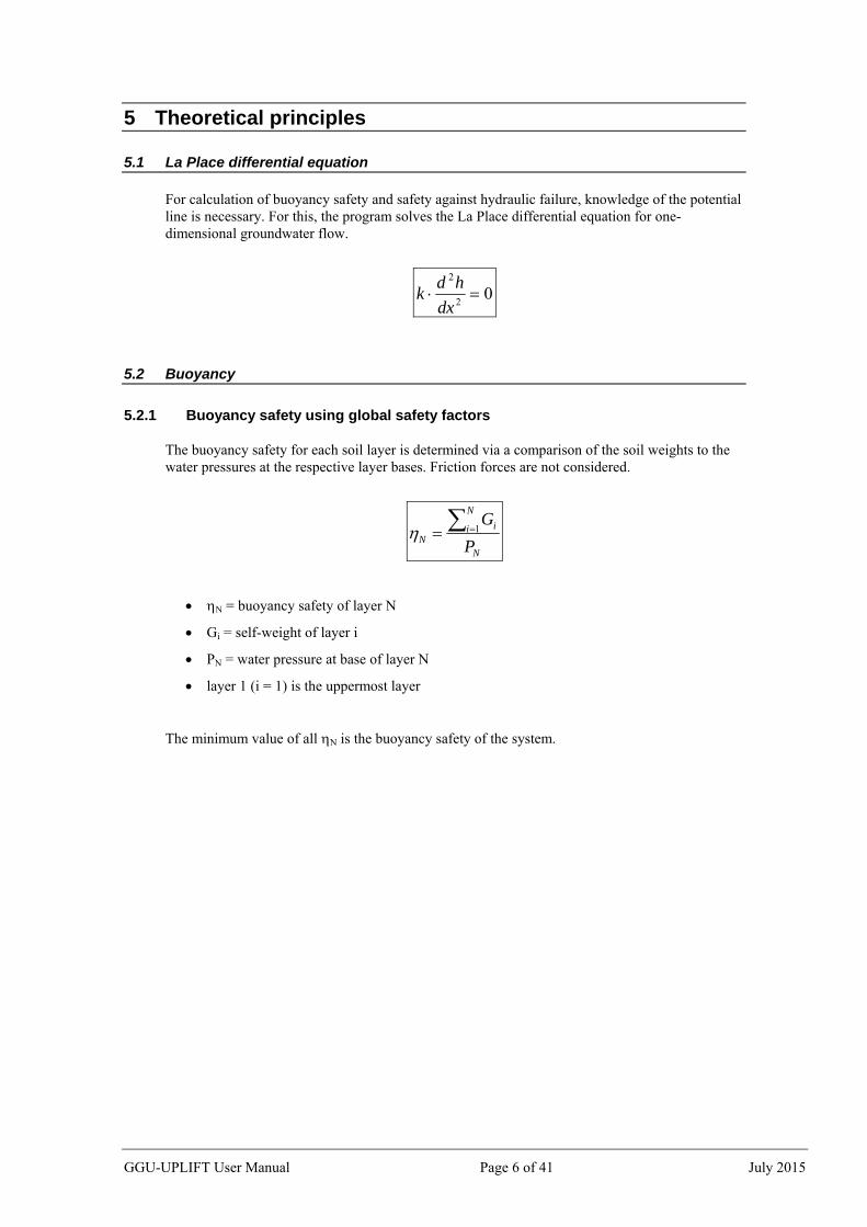
The buoyancy safety for each soil layer is determined via a comparison of the soil weights to the water pressures at the respective layer bases. Friction forces are not considered.
N
N
i iN P
G 1
N = buoyancy safety of layer N
Gi = self-weight of layer i
PN = water pressure at base of layer N
layer 1 (i = 1) is the uppermost layer
The minimum value of all N is the buoyancy safety of the system.
GGU-UPLIFT User Manual Page 6 of 41 July 2015
5.2.2 Utilisation factor (buoyancy) using partial safety factors
Using the partial safety factor concept the following must be verified:
stbg
N
i
istbkdstgk GA ,1 ,,
Ak = the characteristic hydrostatic buoyant force acting on the lower surface of the complete structure, the soil layer in question or the excavation structure
γg,dst = partial factor for destabilising permanent actions in the UPL (EC 7) limit state
Gk,stb = lower characteristic value of stabilising permanent actions
γg,stb = partial factor for stabilising permanent actions in the UPL (EC 7) limit state
layer 1 (i = 1) is the uppermost layer
The so-called utilisation factor µ can also be calculated from this relationship.
stbg
N
i
istbk
dstgkN
G
A
,1 ,
,
µN = utilisation factor of layer N
Utilisation factors ≤ 1.0 mean that sufficient safety is given.
GGU-UPLIFT User Manual Page 7 of 41 July 2015
5.3 Hydraulic failure
5.3.1 Hydraulic failure safety using global safety factors
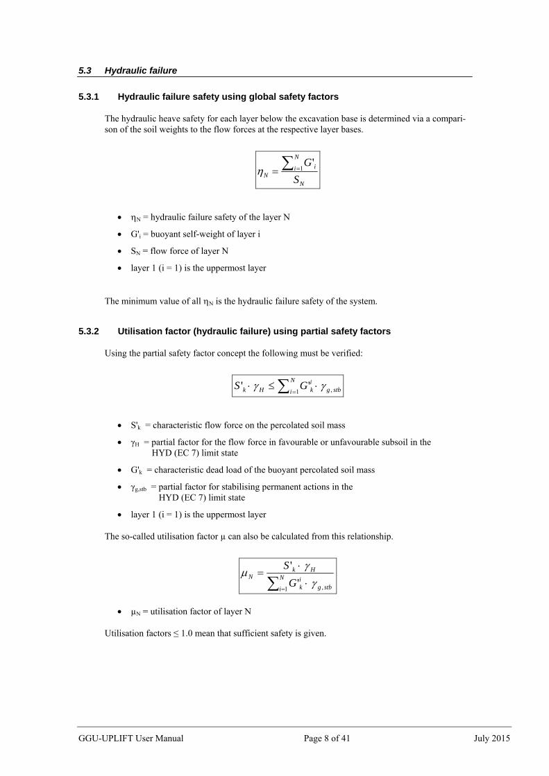
The hydraulic heave safety for each layer below the excavation base is determined via a compari-son of the soil weights to the flow forces at the respective layer bases.
N
N
i iN S
G 1'
N = hydraulic failure safety of the layer N
G'i = buoyant self-weight of layer i
SN = flow force of layer N
layer 1 (i = 1) is the uppermost layer
The minimum value of all N is the hydraulic failure safety of the system.
5.3.2 Utilisation factor (hydraulic failure) using partial safety factors
Using the partial safety factor concept the following must be verified:
stbg
N
i
ikHk GS ,1''
S'k = characteristic flow force on the percolated soil mass
γH = partial factor for the flow force in favourable or unfavourable subsoil in the HYD (EC 7) limit state
G'k = characteristic dead load of the buoyant percolated soil mass
γg,stb = partial factor for stabilising permanent actions in the HYD (EC 7) limit state
layer 1 (i = 1) is the uppermost layer
The so-called utilisation factor µ can also be calculated from this relationship.
stbg
N
i
ik
HkN
G
S
,1'
'
µN = utilisation factor of layer N
Utilisation factors ≤ 1.0 mean that sufficient safety is given.
GGU-UPLIFT User Manual Page 8 of 41 July 2015
GGU-UPLIFT User Manual Page 9 of 41 July 2015
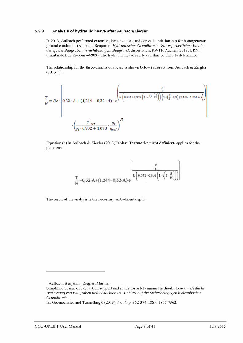
5.3.3 Analysis of hydraulic heave after Aulbach/Ziegler
In 2013, Aulbach performed extensive investigations and derived a relationship for homogeneous ground conditions (Aulbach, Benjamin: Hydraulischer Grundbruch - Zur erforderlichen Einbin-detiefe bei Baugruben in nichtbindigem Baugrund, dissertation, RWTH Aachen, 2013, URN: urn:nbn:de:hbz:82-opus-46909). The hydraulic heave safety can thus be directly determined.
The relationship for the three-dimensional case is shown below (abstract from Aulbach & Ziegler (2013)1 ):
Equation (6) in Aulbach & Ziegler (2013)Fehler! Textmarke nicht definiert. applies for the plane case:
The result of the analysis is the necessary embedment depth.
1 Aulbach, Benjamin; Ziegler, Martin: Simplified design of excavation support and shafts for safety against hydraulic heave = Einfache Bemessung von Baugruben und Schächten im Hinblick auf die Sicherheit gegen hydraulischen Grundbruch. In: Geomechnics and Tunnelling 6 (2013), No. 4, p. 362-374, ISSN 1865-7362.
6 Worked examples
6.1 Example 1: Analysis using partial factors
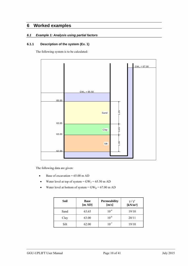
6.1.1 Description of the system (Ex. 1)
The following system is to be calculated:
GWU = 67.00
GWO = 65.50
65.00
63.65
63.00
62.00
1.3
50
.65
1.0
0
Sand
Clay
Silt
The following data are given:
Base of excavation = 65.00 m AD
Water level at top of system = GWT = 65.50 m AD
Water level at bottom of system = GWB = 67.00 m AD
Soil Base [m AD]
Permeability[m/s]
/ ' [kN/m³]
Sand 63.65 10-4 19/10
Clay 63.00 10-8 20/11
Silt 62.00 10-7 19/10
GGU-UPLIFT User Manual Page 10 of 41 July 2015
6.1.2 Create new data set (Ex. 1)
Starting the program afresh you will be directly shown the dialog box of the menu item "File/New". You can enter a project identification, which will then be displayed in the General legend on the screen.
If you activate the "Use absolute heights" check box, the layer height input will be in absolute coordinates (e.g. in m AD). Otherwise, "Top of system" corresponds to 0.0 m and all depth input is positive downwards.
After clicking the "OK" button, the system is represented in section on the screen and the general and soil properties legends displayed, showing default values.
The example can also be analysed using the "Partial safety factor concept (EC 7)", the input and results are the same.
GGU-UPLIFT User Manual Page 11 of 41 July 2015
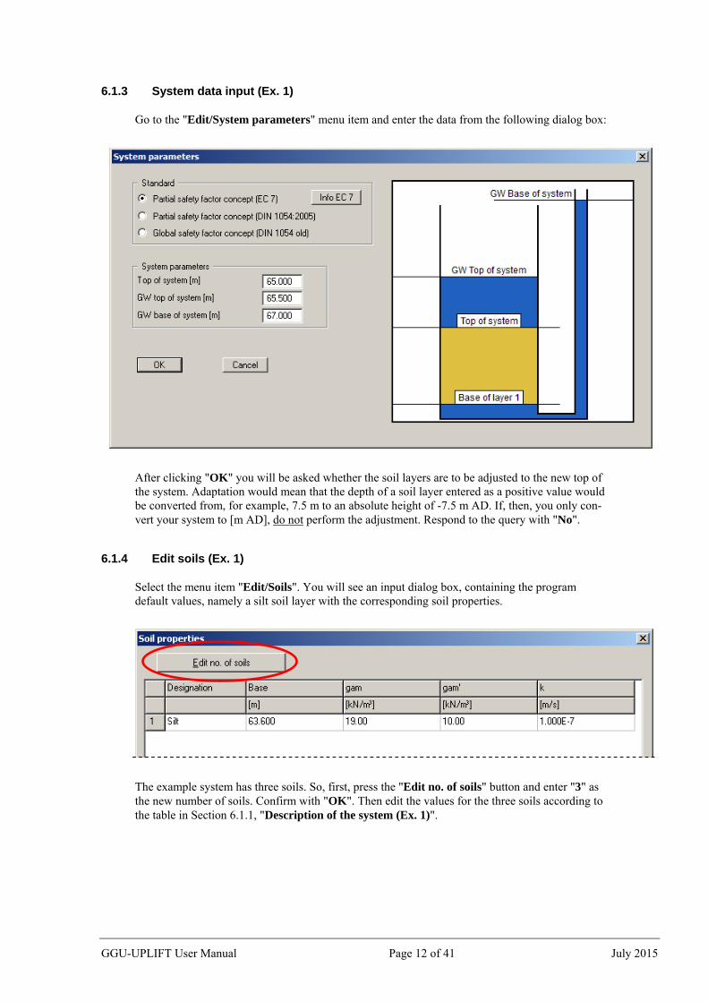
6.1.3 System data input (Ex. 1)
Go to the "Edit/System parameters" menu item and enter the data from the following dialog box:
After clicking "OK" you will be asked whether the soil layers are to be adjusted to the new top of the system. Adaptation would mean that the depth of a soil layer entered as a positive value would be converted from, for example, 7.5 m to an absolute height of -7.5 m AD. If, then, you only con-vert your system to [m AD], do not perform the adjustment. Respond to the query with "No".
6.1.4 Edit soils (Ex. 1)
Select the menu item "Edit/Soils". You will see an input dialog box, containing the program default values, namely a silt soil layer with the corresponding soil properties.
The example system has three soils. So, first, press the "Edit no. of soils" button and enter "3" as the new number of soils. Confirm with "OK". Then edit the values for the three soils according to the table in Section 6.1.1, "Description of the system (Ex. 1)".
GGU-UPLIFT User Manual Page 12 of 41 July 2015
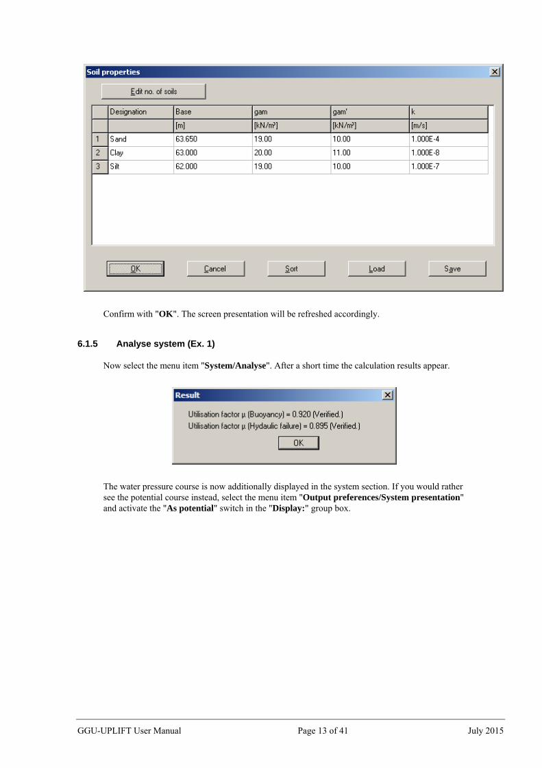
Confirm with "OK". The screen presentation will be refreshed accordingly.
6.1.5 Analyse system (Ex. 1)
Now select the menu item "System/Analyse". After a short time the calculation results appear.
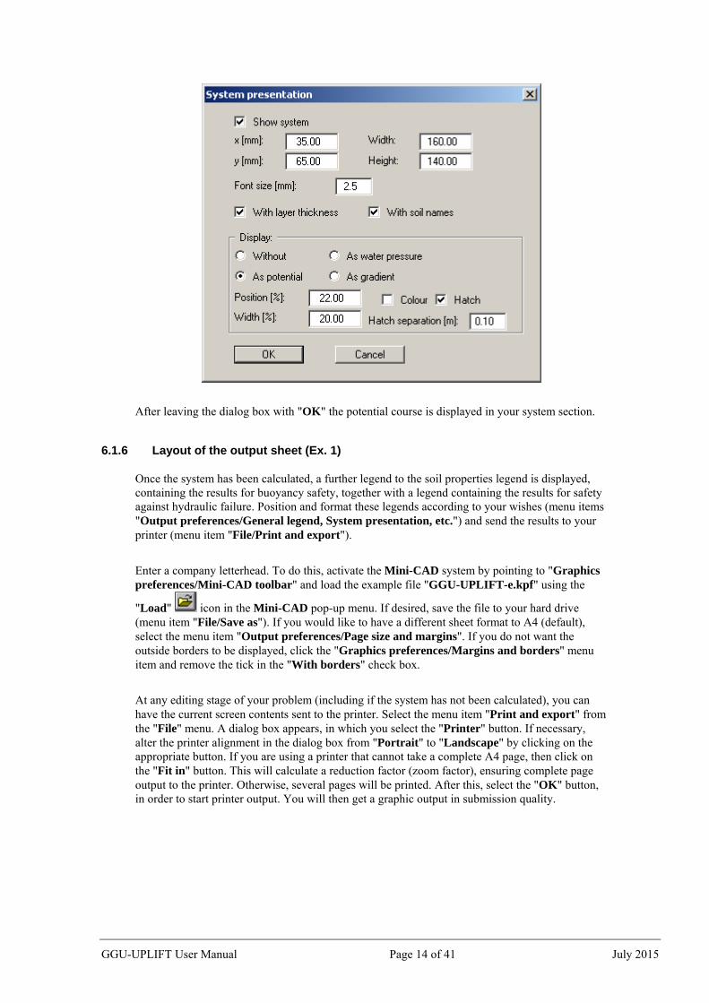
The water pressure course is now additionally displayed in the system section. If you would rather see the potential course instead, select the menu item "Output preferences/System presentation" and activate the "As potential" switch in the "Display:" group box.
GGU-UPLIFT User Manual Page 13 of 41 July 2015
After leaving the dialog box with "OK" the potential course is displayed in your system section.
6.1.6 Layout of the output sheet (Ex. 1)
Once the system has been calculated, a further legend to the soil properties legend is displayed, containing the results for buoyancy safety, together with a legend containing the results for safety against hydraulic failure. Position and format these legends according to your wishes (menu items "Output preferences/General legend, System presentation, etc.") and send the results to your printer (menu item "File/Print and export").
Enter a company letterhead. To do this, activate the Mini-CAD system by pointing to "Graphics preferences/Mini-CAD toolbar" and load the example file "GGU-UPLIFT-e.kpf" using the
"Load" icon in the Mini-CAD pop-up menu. If desired, save the file to your hard drive (menu item "File/Save as"). If you would like to have a different sheet format to A4 (default), select the menu item "Output preferences/Page size and margins". If you do not want the outside borders to be displayed, click the "Graphics preferences/Margins and borders" menu item and remove the tick in the "With borders" check box.
At any editing stage of your problem (including if the system has not been calculated), you can have the current screen contents sent to the printer. Select the menu item "Print and export" from the "File" menu. A dialog box appears, in which you select the "Printer" button. If necessary, alter the printer alignment in the dialog box from "Portrait" to "Landscape" by clicking on the appropriate button. If you are using a printer that cannot take a complete A4 page, then click on the "Fit in" button. This will calculate a reduction factor (zoom factor), ensuring complete page output to the printer. Otherwise, several pages will be printed. After this, select the "OK" button, in order to start printer output. You will then get a graphic output in submission quality.
GGU-UPLIFT User Manual Page 14 of 41 July 2015
6.2 Example 2: Optimising the system
6.2.1 Create new data set (Ex. 2)
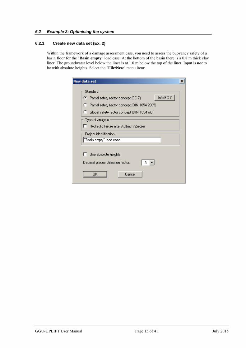
Within the framework of a damage assessment case, you need to assess the buoyancy safety of a basin floor for the "Basin empty" load case. At the bottom of the basin there is a 0.8 m thick clay liner. The groundwater level below the liner is at 1.0 m below the top of the liner. Input is not to be with absolute heights. Select the "File/New" menu item:
GGU-UPLIFT User Manual Page 15 of 41 July 2015
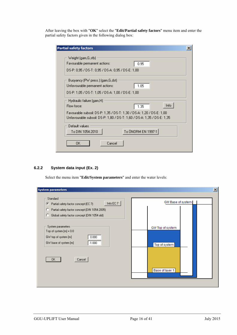
After leaving the box with "OK" select the "Edit/Partial safety factors" menu item and enter the partial safety factors given in the following dialog box:
6.2.2 System data input (Ex. 2)
Select the menu item "Edit/System parameters" and enter the water levels:
GGU-UPLIFT User Manual Page 16 of 41 July 2015
6.2.3 Edit soils (Ex. 2)
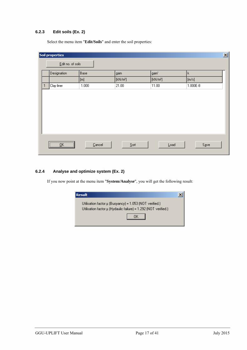
Select the menu item "Edit/Soils" and enter the soil properties:
6.2.4 Analyse and optimize system (Ex. 2)
If you now point at the menu item "System/Analyse", you will get the following result:
GGU-UPLIFT User Manual Page 17 of 41 July 2015
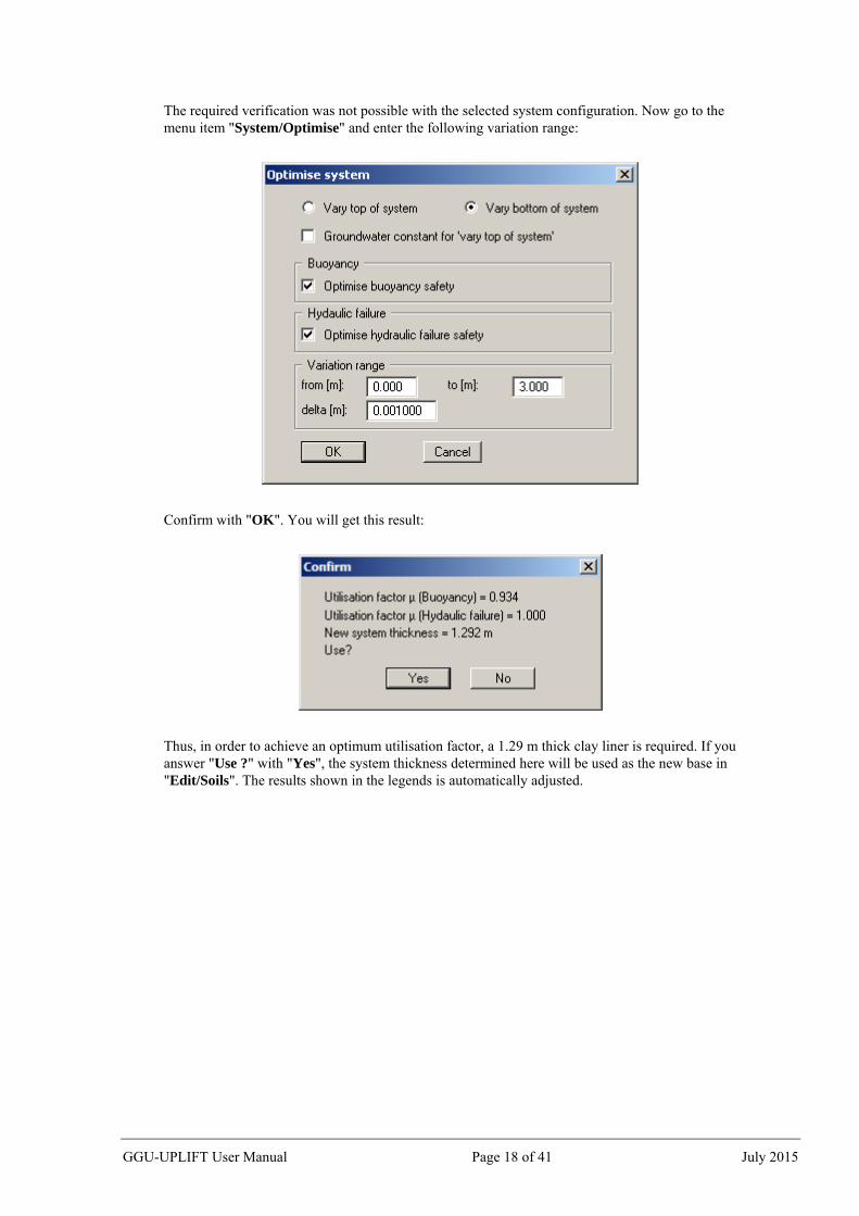
The required verification was not possible with the selected system configuration. Now go to the menu item "System/Optimise" and enter the following variation range:
Confirm with "OK". You will get this result:
Thus, in order to achieve an optimum utilisation factor, a 1.29 m thick clay liner is required. If you answer "Use ?" with "Yes", the system thickness determined here will be used as the new base in "Edit/Soils". The results shown in the legends is automatically adjusted.
GGU-UPLIFT User Manual Page 18 of 41 July 2015
7 Description of menu items
7.1 File menu
7.1.1 "New" menu item
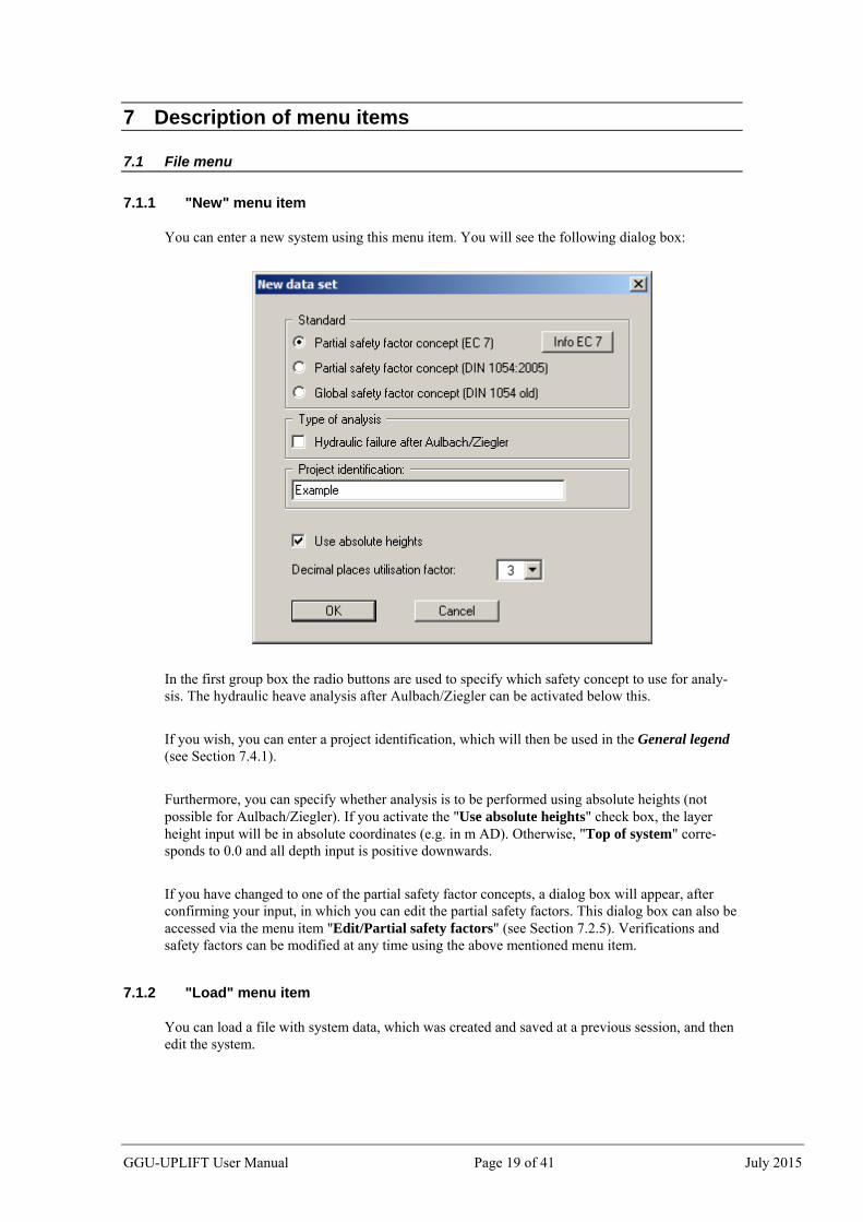
You can enter a new system using this menu item. You will see the following dialog box:
In the first group box the radio buttons are used to specify which safety concept to use for analy-sis. The hydraulic heave analysis after Aulbach/Ziegler can be activated below this.
If you wish, you can enter a project identification, which will then be used in the General legend (see Section 7.4.1).
Furthermore, you can specify whether analysis is to be performed using absolute heights (not possible for Aulbach/Ziegler). If you activate the "Use absolute heights" check box, the layer height input will be in absolute coordinates (e.g. in m AD). Otherwise, "Top of system" corre-sponds to 0.0 and all depth input is positive downwards.
If you have changed to one of the partial safety factor concepts, a dialog box will appear, after confirming your input, in which you can edit the partial safety factors. This dialog box can also be accessed via the menu item "Edit/Partial safety factors" (see Section 7.2.5). Verifications and safety factors can be modified at any time using the above mentioned menu item.
7.1.2 "Load" menu item
You can load a file with system data, which was created and saved at a previous session, and then edit the system.
GGU-UPLIFT User Manual Page 19 of 41 July 2015
7.1.3 "Save" menu item
You can save data entered or edited during program use to a file, in order to have them available at a later date, or to archive them. The data is saved without prompting with the name of the current file.
7.1.4 "Save as" menu item
You can save data entered during program use to an existing file or to a new file, i.e. using a new file name. For reasons of clarity, it makes sense to use ".aft" as file suffix, as this is the suffix used in the file requester box for the menu item "File/Load". If you choose not to enter an extension when saving, ".aft" will be used automatically.
7.1.5 "Printer preferences" menu item
You can edit printer preferences (e.g. swap between portrait and landscape) or change the printer in accordance with WINDOWS conventions.
7.1.6 "Print and export" menu item
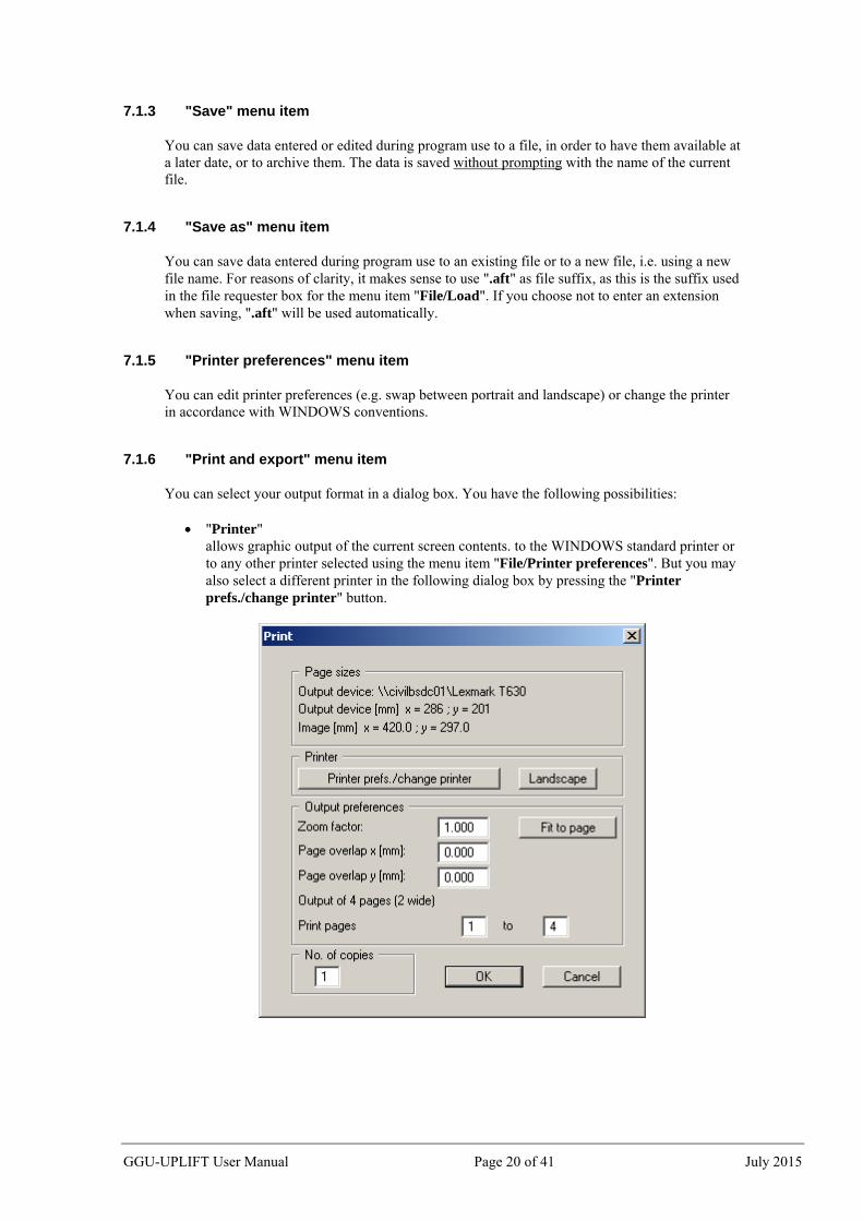
You can select your output format in a dialog box. You have the following possibilities:
"Printer" allows graphic output of the current screen contents. to the WINDOWS standard printer or to any other printer selected using the menu item "File/Printer preferences". But you may also select a different printer in the following dialog box by pressing the "Printer prefs./change printer" button.
GGU-UPLIFT User Manual Page 20 of 41 July 2015
In the upper part of the dialog box, the maximum dimensions which the printer can accept are given. Below this, the dimensions of the image to be printed are given. If the image is larger than the output format of the printer, the image will be printed to several pages (in the above example, 4). In order to facilitate better re-connection of the images, the possibility of entering an overlap for each page, in x and y direction, is given. Alternatively, you also have the possibility of selecting a smaller zoom factor, ensuring output to one page ("Fit to page" button). Following this, you can enlarge to the original format on a copying machine, to ensure true scaling. Furthermore, you may enter the number of copies to be printed.
"DXF file" allows output of the graphics to a XF file. DXF is a common file format for transferring graphics between a variety of applications.
"GGUCAD file" allows output of the graphics to a file, in order to enable further processing with the GGUCAD program. Compared to output as a DXF file this has the advantage that no loss of colour quality occurs during export.
"Clipboard" The graphics are copied to the WINDOWS clipboard. From there, they can be imported into other WINDOWS programs for further processing, e.g. into a word processor. In order to import into any other WINDOWS program you must generally use the "Edit/Paste" function of the respective application.
"Metafile" allows output of the graphics to a file in order to be further processed with third party software. Output is in the standardised EMF format (Enhanced Metafile format). Use of the Metafile format guarantees the best possible quality when transferring graphics.
If you select the "Copy/print area" tool from the toolbar, you can copy parts of the graphics to the clipboard or save them to an EMF file. Alternatively you can send the marked area directly to your printer (see "Tips and tricks", Section 8.3). Using the "Mini-CAD" program module you can also import EMF files generated us-ing other GGU applications into your graphics.
"MiniCAD" allows export of the graphics to a file in order to enable importing to different GGU appli-cations with the Mini-CAD module.
"GGUMiniCAD" allows export of the graphics to a file in order to enable processing in the GGUMiniCAD program.
"Cancel" Printing is cancelled.
GGU-UPLIFT User Manual Page 21 of 41 July 2015
7.1.7 "Batch print" menu item
If you would like to print several appendices at once, select this menu item. You will see the following dialog box:
Create a list of files for printing using "Add" and selecting the desired files. The number of files is displayed in the dialog box header. Using "Delete" you can mark and delete selected individual files from the list. After selecting the "Delete all" button, you can compile a new list. Selection of the desired printer and printer preferences is achieved by pressing the "Printer" button.
You then start printing by using the "Print" button. In the dialog box which then appears you can select further preferences for printer output such as, e.g., the number of copies. These preferences will be applied to all files in the list.
7.1.8 "Exit" menu item
After a confirmation prompt, you can quit the program.
7.1.9 "1, 2, 3, 4" menu items
The "1, 2, 3, 4" menu items show the last four files worked on. By selecting one of these menu items the listed file will be loaded. If you have saved files in any other folder than the program folder, you can save yourself the occasionally onerous rummaging through various sub-folders.
GGU-UPLIFT User Manual Page 22 of 41 July 2015
7.2 Edit menu
7.2.1 "Project identification" menu item
You can enter a description of the data set for this system. The project identification will then be used in the General legend (see section 7.4.1).
7.2.2 "Analysis options" menu item
Using this menu item you can edit the default preferences of the current system, e.g. change the safety factor concept used during analysis. The dialog box corresponds to the box in the menu item "File/New" (see descriptions in Section 7.1.1).
7.2.3 "System parameters" menu item
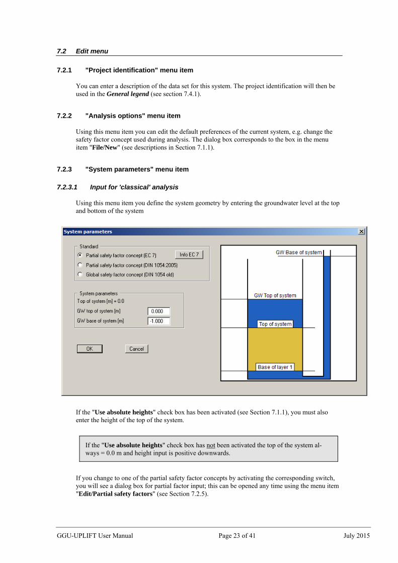
7.2.3.1 Input for 'classical' analysis
Using this menu item you define the system geometry by entering the groundwater level at the top and bottom of the system
If the "Use absolute heights" check box has been activated (see Section 7.1.1), you must also enter the height of the top of the system.
If the "Use absolute heights" check box has not been activated the top of the system al-ways = 0.0 m and height input is positive downwards.
If you change to one of the partial safety factor concepts by activating the corresponding switch, you will see a dialog box for partial factor input; this can be opened any time using the menu item "Edit/Partial safety factors" (see Section 7.2.5).
GGU-UPLIFT User Manual Page 23 of 41 July 2015
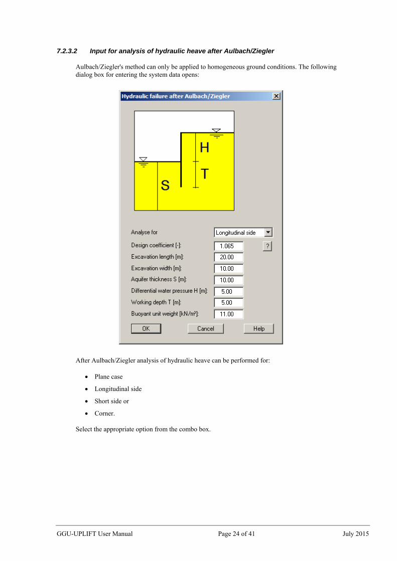
7.2.3.2 Input for analysis of hydraulic heave after Aulbach/Ziegler
Aulbach/Ziegler's method can only be applied to homogeneous ground conditions. The following dialog box for entering the system data opens:
After Aulbach/Ziegler analysis of hydraulic heave can be performed for:
Plane case
Longitudinal side
Short side or
Corner.
Select the appropriate option from the combo box.
GGU-UPLIFT User Manual Page 24 of 41 July 2015
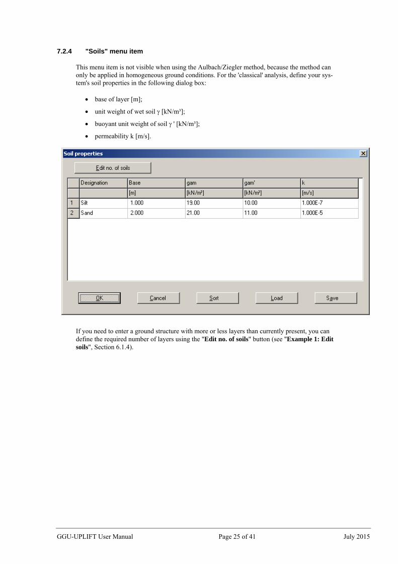
7.2.4 "Soils" menu item
This menu item is not visible when using the Aulbach/Ziegler method, because the method can only be applied in homogeneous ground conditions. For the 'classical' analysis, define your sys-tem's soil properties in the following dialog box:
base of layer [m];
unit weight of wet soil [kN/m³];
buoyant unit weight of soil ' [kN/m³];
permeability k [m/s].
If you need to enter a ground structure with more or less layers than currently present, you can define the required number of layers using the "Edit no. of soils" button (see "Example 1: Edit soils", Section 6.1.4).
GGU-UPLIFT User Manual Page 25 of 41 July 2015
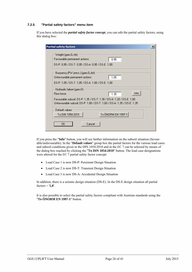
7.2.5 "Partial safety factors" menu item
If you have selected the partial safety factor concept, you can edit the partial safety factors, using this dialog box:
If you press the "Info" button, you will see further information on the subsoil situation (favour-able/unfavourable). In the "Default values" group box the partial factors for the various load cases and subsoil conditions given in the DIN 1054:2010 and in the EC 7 can be selected by means of the dialog box reached by clicking the "To DIN 1054:2010" button. The load case designations were altered for the EC 7 partial safety factor concept:
Load Case 1 is now DS-P: Persistent Design Situation
Load Case 2 is now DS-T: Transient Design Situation
Load Case 3 is now DS-A: Accidental Design Situation
In addition, there is a seismic design situation (DS-E). In the DS-E design situation all partial factors = '1,0'.
It is also possible to select the partial safety factors compliant with Austrian standards using the "To ÖNORM EN 1997-1" button.
GGU-UPLIFT User Manual Page 26 of 41 July 2015
7.3 System menu
7.3.1 "Analyse" menu item
With this menu item you can begin calculating the system. First, a plausibility check of the input data will be carried out. If necessary, you will see an error message, with an appropriate note on corrections. Then a dialog box with the analysis results appears, shown below for a 'classical' analysis:
When using the Aulbach/Ziegler method you will see the following result box, for example:
The resulting utilisation factor µ is given by division of required T/working T.
GGU-UPLIFT User Manual Page 27 of 41 July 2015
7.3.2 "Optimise" menu item
Occasionally, it is desirable to determine the system dimensions which result in a certain, just sufficient, buoyancy safety or sufficient safety against hydraulic failure. This menu item can be helpful here.
In the upper part of the dialog box you specify whether the top of the system or the bottom is to be varied. If you activate the "Vary top of system" switch, you can additionally specify whether the groundwater level is to be kept constant during variation, or whether it is to be kept at a constant distance to the top of the system.
In the "Buoyancy" and "Hydraulic failure" group boxes you can define the safety to be optimised by activating the appropriate check boxes. If you have selected global safety factors as the analysis method, the safety factor input boxes are shown here. These boxes are not shown if you have selected partial safety factors as the analysis method, because in this case the editable partial safety factors ("Edit" menu) are used automatically.
In the "Variation range" group box you define the range and the increments for optimisation.
An example for system optimising can be found in Section 6.2, "Example 2: Optimising the system".
GGU-UPLIFT User Manual Page 28 of 41 July 2015
7.4 Output preferences menu
7.4.1 "General legend" menu item
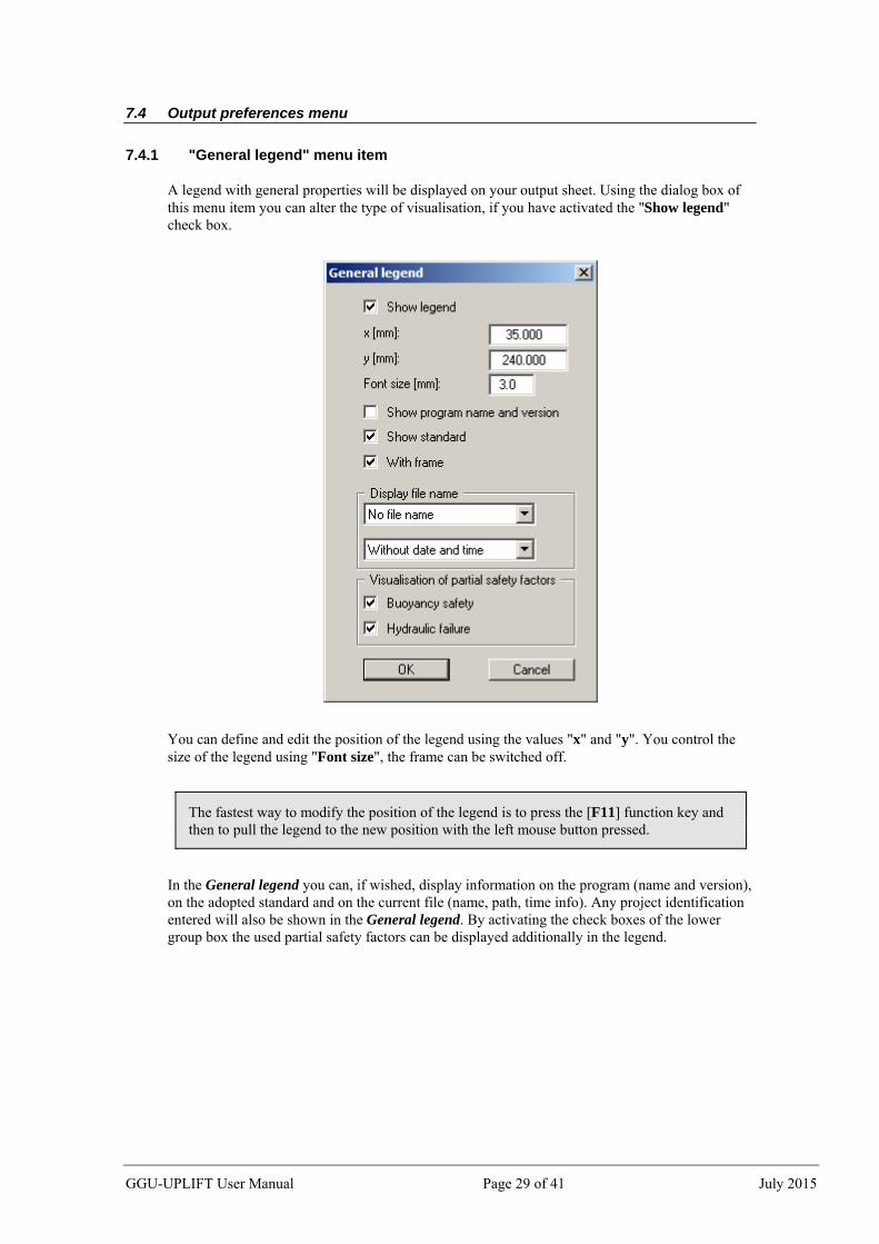
A legend with general properties will be displayed on your output sheet. Using the dialog box of this menu item you can alter the type of visualisation, if you have activated the "Show legend" check box.
You can define and edit the position of the legend using the values "x" and "y". You control the size of the legend using "Font size", the frame can be switched off.
The fastest way to modify the position of the legend is to press the [F11] function key and then to pull the legend to the new position with the left mouse button pressed.
In the General legend you can, if wished, display information on the program (name and version), on the adopted standard and on the current file (name, path, time info). Any project identification entered will also be shown in the General legend. By activating the check boxes of the lower group box the used partial safety factors can be displayed additionally in the legend.
GGU-UPLIFT User Manual Page 29 of 41 July 2015
7.4.2 "System presentation" menu item
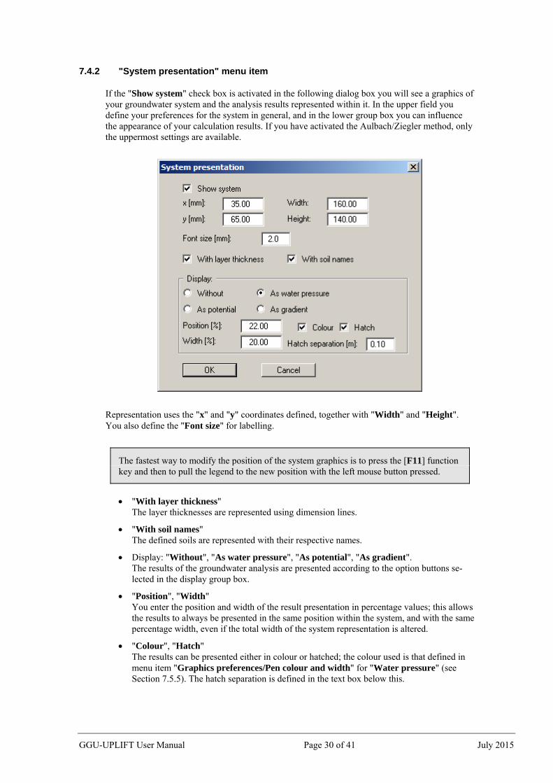
If the "Show system" check box is activated in the following dialog box you will see a graphics of your groundwater system and the analysis results represented within it. In the upper field you define your preferences for the system in general, and in the lower group box you can influence the appearance of your calculation results. If you have activated the Aulbach/Ziegler method, only the uppermost settings are available.
Representation uses the "x" and "y" coordinates defined, together with "Width" and "Height". You also define the "Font size" for labelling.
The fastest way to modify the position of the system graphics is to press the [F11] function key and then to pull the legend to the new position with the left mouse button pressed.
"With layer thickness" The layer thicknesses are represented using dimension lines.
"With soil names" The defined soils are represented with their respective names.
Display: "Without", "As water pressure", "As potential", "As gradient". The results of the groundwater analysis are presented according to the option buttons se-lected in the display group box.
"Position", "Width" You enter the position and width of the result presentation in percentage values; this allows the results to always be presented in the same position within the system, and with the same percentage width, even if the total width of the system representation is altered.
"Colour", "Hatch" The results can be presented either in colour or hatched; the colour used is that defined in menu item "Graphics preferences/Pen colour and width" for "Water pressure" (see Section 7.5.5). The hatch separation is defined in the text box below this.
GGU-UPLIFT User Manual Page 30 of 41 July 2015
7.4.3 "Buoyancy safety legend" menu item
When the system has been calculated, the buoyancy safety results can be displayed in a legend. You can alter the shape and appearance of the legend, if the "Show legend" check box is acti-vated.
You can define and edit the position of the legend using the values "x" and "y". The size of the legend is controlled by the values for "Font size" and "Max. no. of lines"; where necessary, sev-eral columns are used.
7.4.4 "Hydraulic failure safety legend" menu item
When the system has been calculated, the hydraulic failure safety results can be displayed in a legend. You can alter the shape and appearance of the legend, if the "Show legend" check box is activated.
You can define and edit the position of the legend using the values "x" and "y". The size of the legend is controlled by the values for "Font size" and "Max. no. of lines"; where necessary, sev-eral columns are used.
GGU-UPLIFT User Manual Page 31 of 41 July 2015
7.4.5 "Soil properties legend" menu item
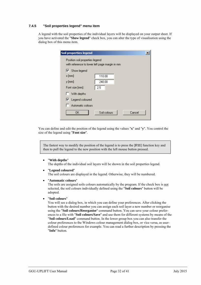
A legend with the soil properties of the individual layers will be displayed on your output sheet. If you have activated the "Show legend" check box, you can alter the type of visualisation using the dialog box of this menu item.
You can define and edit the position of the legend using the values "x" and "y". You control the size of the legend using "Font size".
The fastest way to modify the position of the legend is to press the [F11] function key and then to pull the legend to the new position with the left mouse button pressed.
"With depths" The depths of the individual soil layers will be shown in the soil properties legend.
"Legend coloured" The soil colours are displayed in the legend. Otherwise, they will be numbered.
"Automatic colours" The soils are assigned soils colours automatically by the program. If the check box is not selected, the soil colours individually defined using the "Soil colours" button will be adopted.
"Soil colours" You will see a dialog box, in which you can define your preferences. After clicking the button with the desired number you can assign each soil layer a new number or reorganise using the "Soil colours/Reorganise" command button. You can save your colour prefer-ences to a file with "Soil colours/Save" and use them for different systems by means of the "Soil colours/Load" command button. In the lower group box you can also transfer the colour preferences to the Windows colour management dialog box, or vice versa, as user-defined colour preferences for example. You can read a further description by pressing the "Info" button.
GGU-UPLIFT User Manual Page 32 of 41 July 2015
7.4.6 "Page size and margins" menu item
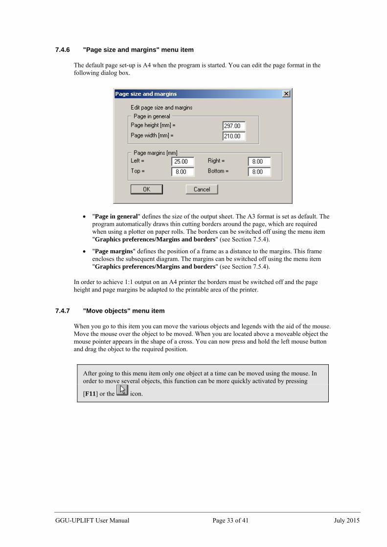
The default page set-up is A4 when the program is started. You can edit the page format in the following dialog box.
"Page in general" defines the size of the output sheet. The A3 format is set as default. The program automatically draws thin cutting borders around the page, which are required when using a plotter on paper rolls. The borders can be switched off using the menu item "Graphics preferences/Margins and borders" (see Section 7.5.4).
"Page margins" defines the position of a frame as a distance to the margins. This frame encloses the subsequent diagram. The margins can be switched off using the menu item "Graphics preferences/Margins and borders" (see Section 7.5.4).
In order to achieve 1:1 output on an A4 printer the borders must be switched off and the page height and page margins be adapted to the printable area of the printer.
7.4.7 "Move objects" menu item
When you go to this item you can move the various objects and legends with the aid of the mouse. Move the mouse over the object to be moved. When you are located above a moveable object the mouse pointer appears in the shape of a cross. You can now press and hold the left mouse button and drag the object to the required position.
After going to this menu item only one object at a time can be moved using the mouse. In order to move several objects, this function can be more quickly activated by pressing
[F11] or the icon.
GGU-UPLIFT User Manual Page 33 of 41 July 2015
7.5 Graphics preferences menu
7.5.1 "Refresh and zoom" menu item
The program works on the principle of What you see is what you get. This means that the screen presentation represents, overall, what you will see on your printer. In the last consequence, this would mean that the screen presentation would have to be refreshed after every alteration you make. For reasons of efficiency and as this can take several seconds for complex screen contents, the screen is not refreshed after every alteration.
If, e.g., after using the zoom function (see below), only part of the image is visible, you can achie-ve a complete view using this menu item.
A zoom factor between 0.4 and 8.0 can be entered in the input box. By then clicking on "Use" to exit the box the current factor is accepted. By clicking on the "0.4", "0.6", etc. buttons, the se-lected factor is used directly and the dialog box closed.
It is much simpler, however, to get a complete overview using [Esc]. Pressing [Esc] allows a com-plete screen presentation using the zoom factor specified in this menu item. The [F2] key allows screen refreshing without altering the coordinates and zoom factor.
7.5.2 "Zoom info" menu item
By clicking two diametrically opposed points you can enlarge a section of the screen in order to view details better. An information box provides information on activating the zoom function and on available options.
7.5.3 "Legend font selection" menu item
With this menu item you can switch to a different true-type font. All available true-type fonts are displayed in the dialog box.
7.5.4 "Margins and borders" menu item
The program automatically draws thin cutting edges around the page, which are required when using a plotter on paper rolls. Page margins (see menu item "Output preferences/Page size and margins", Section 7.4.6) defines the position of a frame as a distance to the cutting border. This frame encloses the subsequent diagram. You can switch off the lines by deactivating the "With margins" and "With borders" check boxes.
GGU-UPLIFT User Manual Page 34 of 41 July 2015
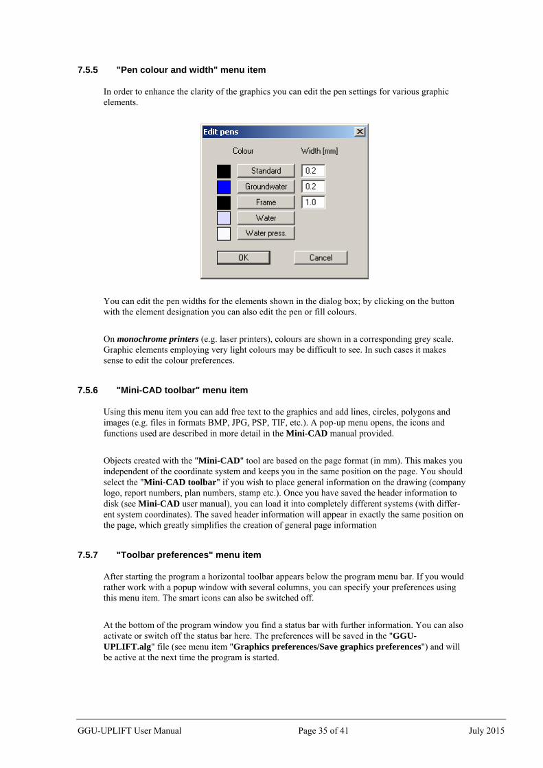
7.5.5 "Pen colour and width" menu item
In order to enhance the clarity of the graphics you can edit the pen settings for various graphic elements.
You can edit the pen widths for the elements shown in the dialog box; by clicking on the button with the element designation you can also edit the pen or fill colours.
On monochrome printers (e.g. laser printers), colours are shown in a corresponding grey scale. Graphic elements employing very light colours may be difficult to see. In such cases it makes sense to edit the colour preferences.
7.5.6 "Mini-CAD toolbar" menu item
Using this menu item you can add free text to the graphics and add lines, circles, polygons and images (e.g. files in formats BMP, JPG, PSP, TIF, etc.). A pop-up menu opens, the icons and functions used are described in more detail in the Mini-CAD manual provided.
Objects created with the "Mini-CAD" tool are based on the page format (in mm). This makes you independent of the coordinate system and keeps you in the same position on the page. You should select the "Mini-CAD toolbar" if you wish to place general information on the drawing (company logo, report numbers, plan numbers, stamp etc.). Once you have saved the header information to disk (see Mini-CAD user manual), you can load it into completely different systems (with differ-ent system coordinates). The saved header information will appear in exactly the same position on the page, which greatly simplifies the creation of general page information
7.5.7 "Toolbar preferences" menu item
After starting the program a horizontal toolbar appears below the program menu bar. If you would rather work with a popup window with several columns, you can specify your preferences using this menu item. The smart icons can also be switched off.
At the bottom of the program window you find a status bar with further information. You can also activate or switch off the status bar here. The preferences will be saved in the "GGU-UPLIFT.alg" file (see menu item "Graphics preferences/Save graphics preferences") and will be active at the next time the program is started.
GGU-UPLIFT User Manual Page 35 of 41 July 2015
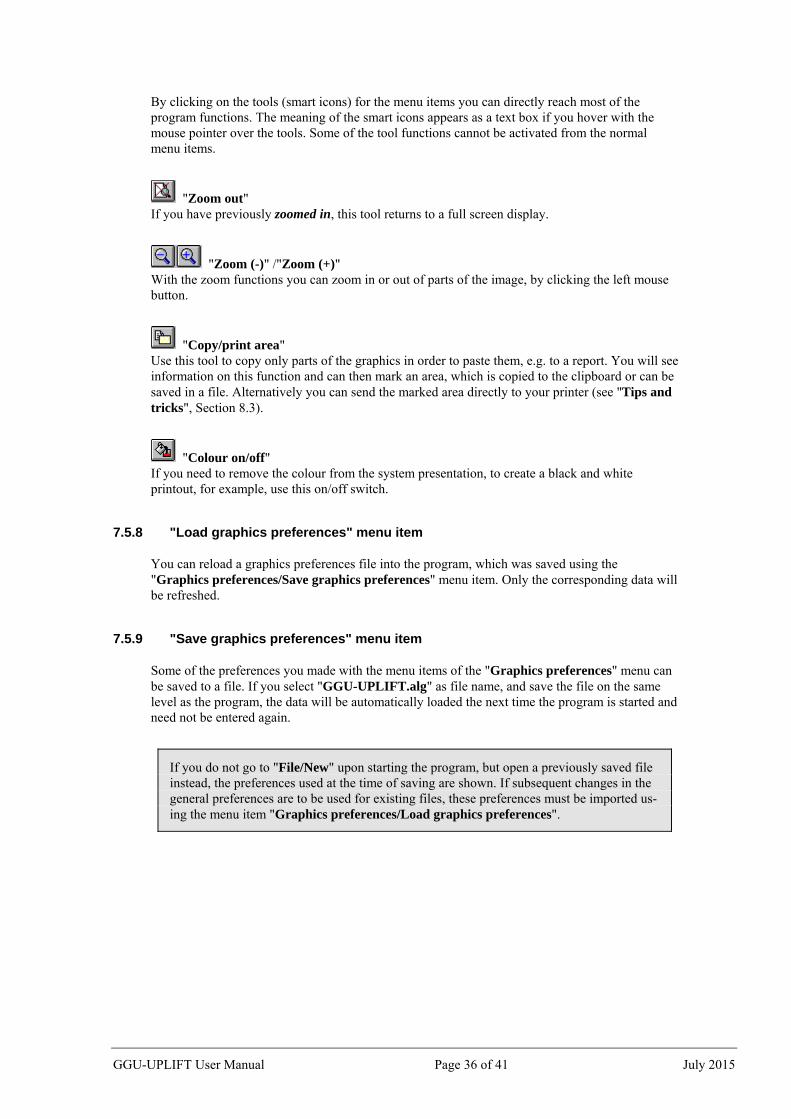
By clicking on the tools (smart icons) for the menu items you can directly reach most of the program functions. The meaning of the smart icons appears as a text box if you hover with the mouse pointer over the tools. Some of the tool functions cannot be activated from the normal menu items.
"Zoom out" If you have previously zoomed in, this tool returns to a full screen display.
"Zoom (-)" /"Zoom (+)" With the zoom functions you can zoom in or out of parts of the image, by clicking the left mouse button.
"Copy/print area" Use this tool to copy only parts of the graphics in order to paste them, e.g. to a report. You will see information on this function and can then mark an area, which is copied to the clipboard or can be saved in a file. Alternatively you can send the marked area directly to your printer (see "Tips and tricks", Section 8.3).
"Colour on/off" If you need to remove the colour from the system presentation, to create a black and white printout, for example, use this on/off switch.
7.5.8 "Load graphics preferences" menu item
You can reload a graphics preferences file into the program, which was saved using the "Graphics preferences/Save graphics preferences" menu item. Only the corresponding data will be refreshed.
7.5.9 "Save graphics preferences" menu item
Some of the preferences you made with the menu items of the "Graphics preferences" menu can be saved to a file. If you select "GGU-UPLIFT.alg" as file name, and save the file on the same level as the program, the data will be automatically loaded the next time the program is started and need not be entered again.
If you do not go to "File/New" upon starting the program, but open a previously saved file instead, the preferences used at the time of saving are shown. If subsequent changes in the general preferences are to be used for existing files, these preferences must be imported us-ing the menu item "Graphics preferences/Load graphics preferences".
GGU-UPLIFT User Manual Page 36 of 41 July 2015
7.6 ? menu
7.6.1 "Copyright" menu item
You will see a copyright message and information on the program version number.
The "System" button shows information on your computer configuration and the folders used by GGU-UPLIFT.
7.6.2 "Help" menu item
The GGU-UPLIFT manual is opened as a PDF document. The help function can also be accessed using the [F1] function key.
7.6.3 "GGU on the web" menu item
Using this menu item you can access the GGU Software website: www.ggu-software.com. Keep in touch with new program versions and the regular download offers.
If you would like to be automatically notified about program innovations, please register for the Newsletter in our Knowledge Base. Go to the following website: http://kbase.civilserve.com.
7.6.4 "GGU support" menu item
This menu item takes to the GGU-Software Support area at www.ggu-software.com.
7.6.5 "What’s new ?" menu item
You will see information on program improvements and bug fixes in comparison to older ver-sions.
7.6.6 "Language preferences" menu item
This menu item allows you to switch the menus and the graphics from German to English and vice versa. To work in German, deactivate the two check boxes "Dialoge + Menüs übersetzen (translate dialogues, menus)" und "Graphiktexte übersetzen (translate graphics)".
Alternatively, you can work bilingually, e.g. with German dialog boxes but with graphic output in English. The program always starts with the language setting applicable when it was last ended.
You can scroll the screen with the keyboard using the cursor keys and the [Page up] and [Page down] keys. By clicking and pulling with the mouse, with [Ctrl] pressed, you activate the zoom function, i.e. the selected section will fill the screen. Furthermore you can use the mouse wheel to zoom in/out or scrolling the screen presentation. The following mouse wheel functions are available:
[Shift] + mouse wheel up = move screen image right
[Shift] + mouse wheel down = move screen image left
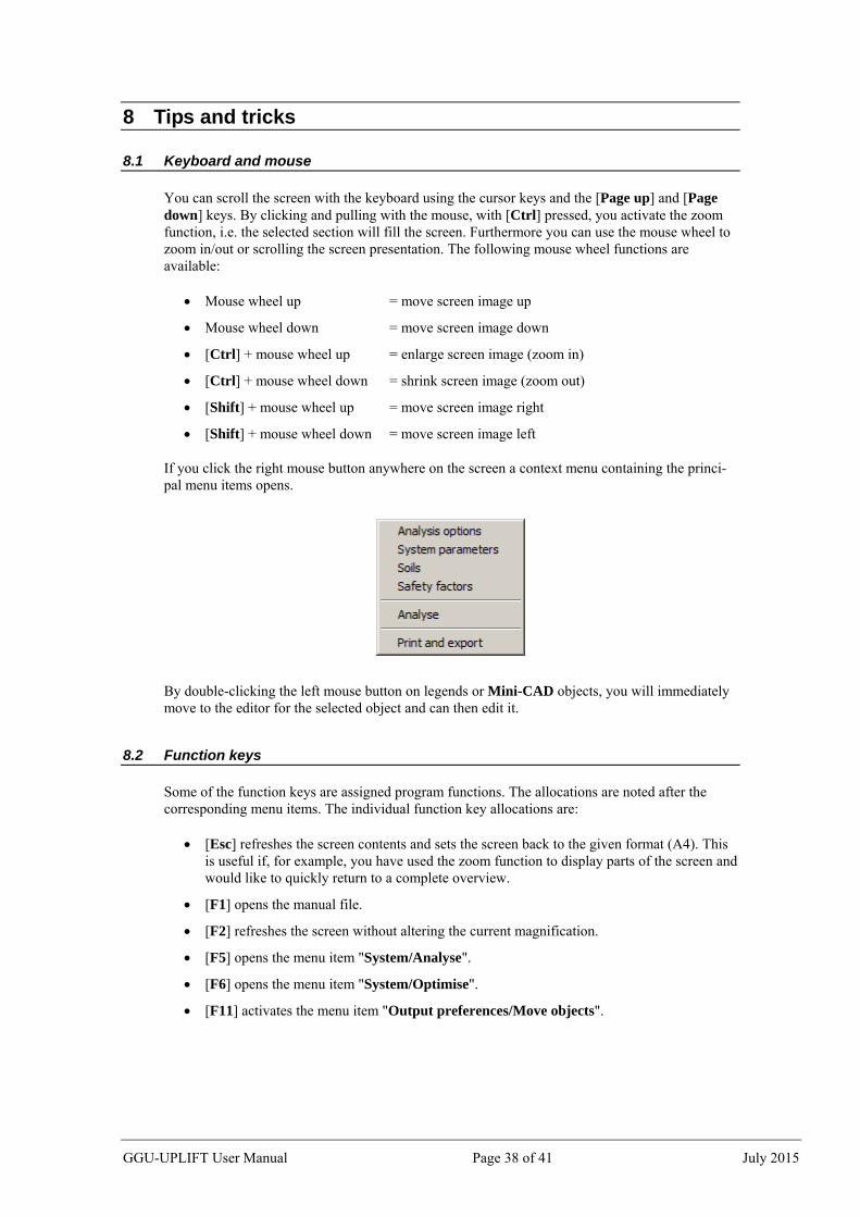
If you click the right mouse button anywhere on the screen a context menu containing the princi-pal menu items opens.
By double-clicking the left mouse button on legends or Mini-CAD objects, you will immediately move to the editor for the selected object and can then edit it.
8.2 Function keys
Some of the function keys are assigned program functions. The allocations are noted after the corresponding menu items. The individual function key allocations are:
[Esc] refreshes the screen contents and sets the screen back to the given format (A4). This is useful if, for example, you have used the zoom function to display parts of the screen and would like to quickly return to a complete overview.
[F1] opens the manual file.
[F2] refreshes the screen without altering the current magnification.
[F5] opens the menu item "System/Analyse".
[F6] opens the menu item "System/Optimise".
[F11] activates the menu item "Output preferences/Move objects".
GGU-UPLIFT User Manual Page 38 of 41 July 2015
8.3 "Copy/print area" icon
A dialog box opens when the "Copy/print area" icon in the menu toolbar is clicked, de-scribing the options available for this function. For example, using this icon it is possible to either copy areas of the screen graphics and paste them into the report, or send them directly to a printer.
In the dialog box, first select where the copied area should be transferred to: "Clipboard", "File" or "Printer". The cursor is displayed as a cross after leaving the dialog box and, keeping the left mouse button pressed, the required area may be enclosed. If the marked area does not suit your requirements, abort the subsequent boxes and restart the function by clicking the icon again.
If "Clipboard" was selected, move to the MS Word document (for example) after marking the area and paste the copied graphics using "Edit/Paste".
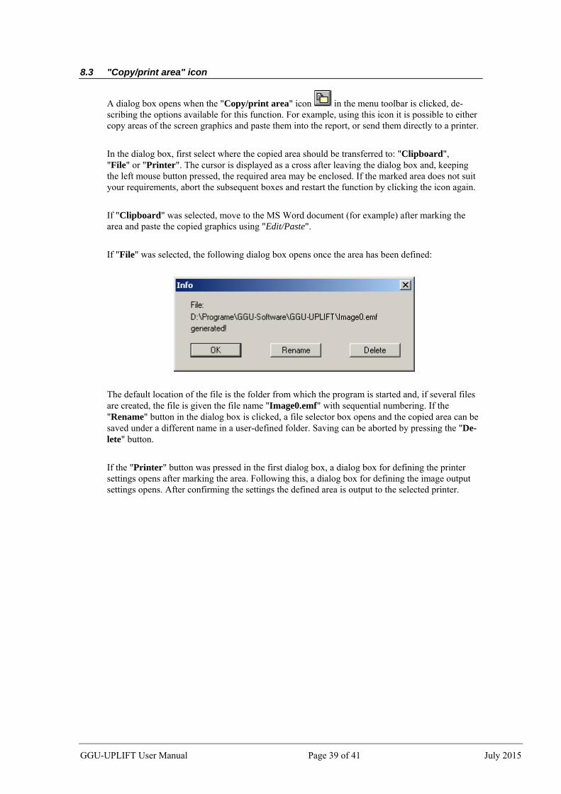
If "File" was selected, the following dialog box opens once the area has been defined:
The default location of the file is the folder from which the program is started and, if several files are created, the file is given the file name "Image0.emf" with sequential numbering. If the "Rename" button in the dialog box is clicked, a file selector box opens and the copied area can be saved under a different name in a user-defined folder. Saving can be aborted by pressing the "De-lete" button.
If the "Printer" button was pressed in the first dialog box, a dialog box for defining the printer settings opens after marking the area. Following this, a dialog box for defining the image output settings opens. After confirming the settings the defined area is output to the selected printer.
GGU-UPLIFT User Manual Page 39 of 41 July 2015
9 Index
A Absolute heights, use.................................. 11, 19 Aulbach/Ziegler, activate method..................... 19
B Buoyancy safety, analysis using global
safety factors .................................................. 6 Buoyancy safety, analysis using partial
I Installation .......................................................... 4
K Knowledge Base, access................................... 37
L La Place differential equation............................. 6 Language preferences ................................... 5, 37 Legend, move with mouse................................ 33 Licence protection .............................................. 4 Load cases, adopt in accordance with
DIN 1054-2005/EC 7 ................................... 26
M Manual, open as PDF file ................................. 37 Metafile, export ................................................ 21 Mini-CAD file, export ...................................... 21 Mini-CAD, use ................................................. 35 Mouse click functions....................................... 38 Mouse wheel functions ..................................... 38
O Objects, move with mouse................................ 33 ÖNORM EN 1997-1,
ÖNORM EN 1997-1 .................................... 26 Pen preferences, edit for graphical elements .... 35 Permeability, define.......................................... 25
GGU-UPLIFT User Manual Page 40 of 41 July 2015
GGU-UPLIFT User Manual Page 41 of 41 July 2015
Potential course, activate visualisation ............. 13 Print, graphics................................................... 20 Print, section......................................... 21, 36, 39 Print, several files ............................................. 22 Printer preferences............................................ 20 Program, display name in legend...................... 29 Program, load/save preferences ........................ 36 Program, show improvements .......................... 37 Program, show information .............................. 37 Project data, add via Mini-CAD ....................... 35 Project identification, display ........................... 29 Project identification, enter............................... 23
R Record description, enter.................................. 23
S Safety concept, select ....................................... 19 Safety factor, display in legend ........................ 31 Scroll the screen ............................................... 38 Smart icons, for menu items ............................. 36 Soil colour/number, activate display ................ 32 Soil layers, adjust to absolute heights............... 12 Soil layers, define ............................................. 12 Soil names, activate visualisation ..................... 30 Soil properties, display in legend ..................... 32 Soil properties, enter......................................... 25 Soil properties, enter after Aulbach/Ziegler ..... 24 Soil, define colours........................................... 32 Standard, display in legend............................... 29 Status bar main program, activate .................... 35 System properties, display in legend ................ 29
System, show information ................................ 37
T Toolbar, edit for menu items ............................ 35 Translation, activate ......................................... 37 True-type font................................................... 34
U Utilisation factor, buoyancy ............................... 7 Utilisation factor, display in legend.................. 31 Utilisation factor, hydraulic heave...................... 8
V Variation range, specify for optimisation ......... 28 Version number, display in a message box....... 37 Version number, display in legend ................... 29
W Water pressure course, activate visualisation ... 13 Water pressure, define fill colour ..................... 35 Weight of soil, define ....................................... 25 What you see is what you get ........................... 34
Z Zoom factor, define for full-screen display ...... 34 Zoom function, activate........................ 34, 36, 38


![[Manual] Ggu-footing [2012]](https://static.documents.pub/doc/80x56/55cf99ba550346d0339ee181/manual-ggu-footing-2012.jpg)


