20
CALCULATION OF LOAD CAPACITY OF GEAR TEETH BY H. SIGG Chief Design Engineer
CALCULATION OF LOAD CAPACITY OF GEAR TEETH
BY
H. SIGG
Chief Design Engineer

I N D E X
Introduction
1. The formulae by ISO
2. The MAAG method to predict
the scoring resistance
3. The AGMA approach; Service factor

Calculation of load capacity of gear teeth
Introduc~ion
The load capacity of two meshing gears is limited
by three main factors:
1. Bending strength of the teeth.
2. Surface durability of the tooth flanks.
3. Scoring resistance of the tooth flanks
There are two main methods known today to predict
strength and durability with good accuracy:
1. Calculation by ISO (International Standard Organisation)
2- Calculation by AGMA (American Gear Manufacturers
Association)
The ISO-standards are used predominantly by European
gear manufacturers. The formulae given· in the MAAG
Handbook are based on these.
In the United States gears are calculated by the AGMA
standard.
Basically~ the two methods are not too much different.
However~ there are some discrepancies, especially where
permissible tooth loads are concerned; e.g. surface
hardened gears are not yet as widely used in the U.S.A.
as in Europe. It is probably for this reason that the
relation between the allowable stresses for surface
hardened and through-hardened teeth is smaller in the
AGMA-standards than in the ISO recommendation.
The main formulae by ISO are listed in this paper. But
the discussion of the various factors i s outside the

- 2 -
scope of this paper; we refer to a pUblication by
VDI (1).
The fin a l ISO-st a ndard has not yet been published.
It is e xpect e d that it will be available by 1974.
AGr-1A has introduced the so-called "Service Factor".
This factor and its calculation are discussed in this
paper.
The third criteria, the calculation of the scoring
resistance, has gained in importance in recent years.
Especially in surface hardened, high speed/high power
gearing it is th e scoring limit together with the
tooth bending strength which determine the size of
the gear.
However, neither AG MA nor ISO have so far provided
a formula to predict the tooth loading where scoring
must be expected. In this paper a calculation m~thod
is described which is based on Prof. Blok's flash
temperature theory and which has been in use by MAAG for
many years.
- :;; -
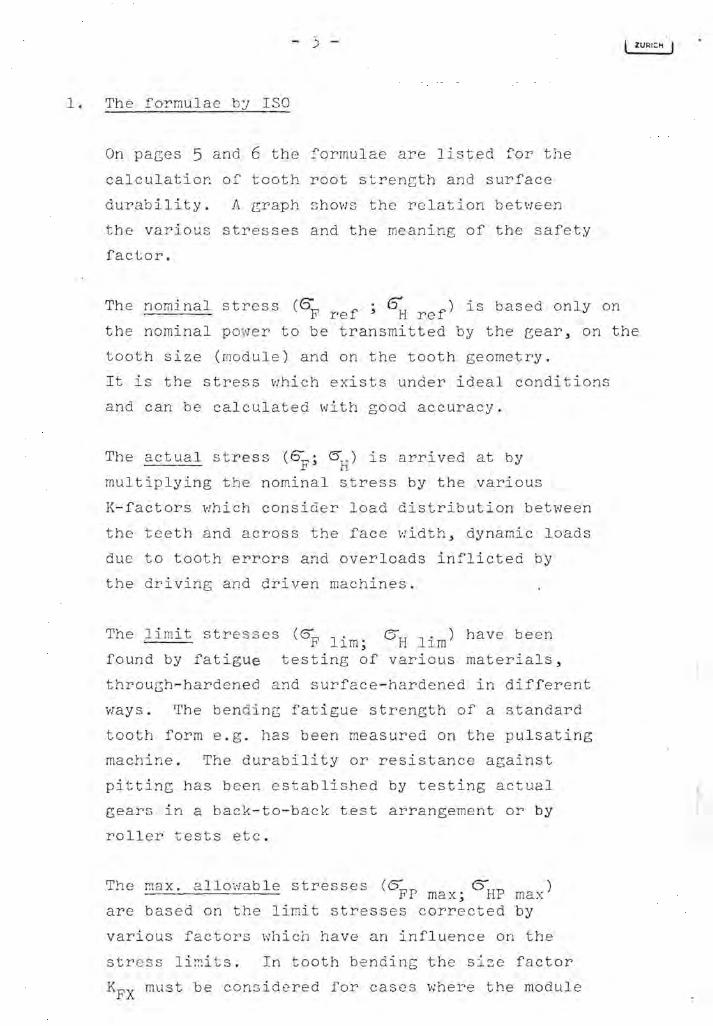
1. The formulae by ISO
On pages 5 and 6 the formulae are listed for the
calculatior. of tooth root strength and surface
durability. A graph shows the relation between
the various stresses and the meaning of the safety
factor.
The nominal stress (ffF f; ()H f) is based only on re re
ZU""CH
the nominal powe r to be transmitted by the eear, on the
tooth size (module) and on the tooth geometry .
It is the stress which exists under ideal conditions
and can be calculated with good accuracy.
The actual stress (SF; 0H) is arrived at by
multiplying the nominal stress by the various
K-factors which consider load distribution between
the teeth and across the face width, dynamic loads
due to tooth errors and overloads inflicted by
the driving and driven machines.
The limit stresse s (oF lim; 0H lim) have been
found by fatigue testing of various materials,
through-hardened and surface-hardened ir. different
ways. The bend ing fatigue strength of a standard
tooth form e.g. has been measured on the pulsating
machine. The durability or resistance against
pitting has been established by testing actual
gears in a back-to-back test arrangement or by
rolle~ tests etc.
The max. allowable stresses (oFP D.}JP ) max; 1 max are based on the limit stresses corrected by
various factors which have an influence on the
stres s limits. In tooth bending the size factor
KFX must be considered for cases where the module

is considerably larger than the module of
the test gear. Similar factors are introduced in
determining ~HP : The lube oil has an max influence, also the peripheral speed at the
pitch circle, the surface roughness of the
tooth flanks and the hardness ratio of the
pinion and gear material.
The safety factor is simply derived by dividing
the max. allowable stress by the actual stress.

- 5 -
1.1 Calculation of tooth root strengt h ( ISO-Proposal)
y
K Fx
SF
KFo(
K Ff3
Kv
KI ;/; './ . -;:/< .. ~/; ///~
./ ./ ... ,.. /'
I~~/·' ./ /. / / . ///./ . ,'" ....
Nominal tooth root st r ess :
m n
Actual tooth root stress:
Max. allowable toot h root stress:
6. - (5 FP max - F lim I~X
Safety factor: (tooth fr a cture)
S = 0FP max F ----
6" F
F lim
°FP max
6 F
6 F ref
- 6 -
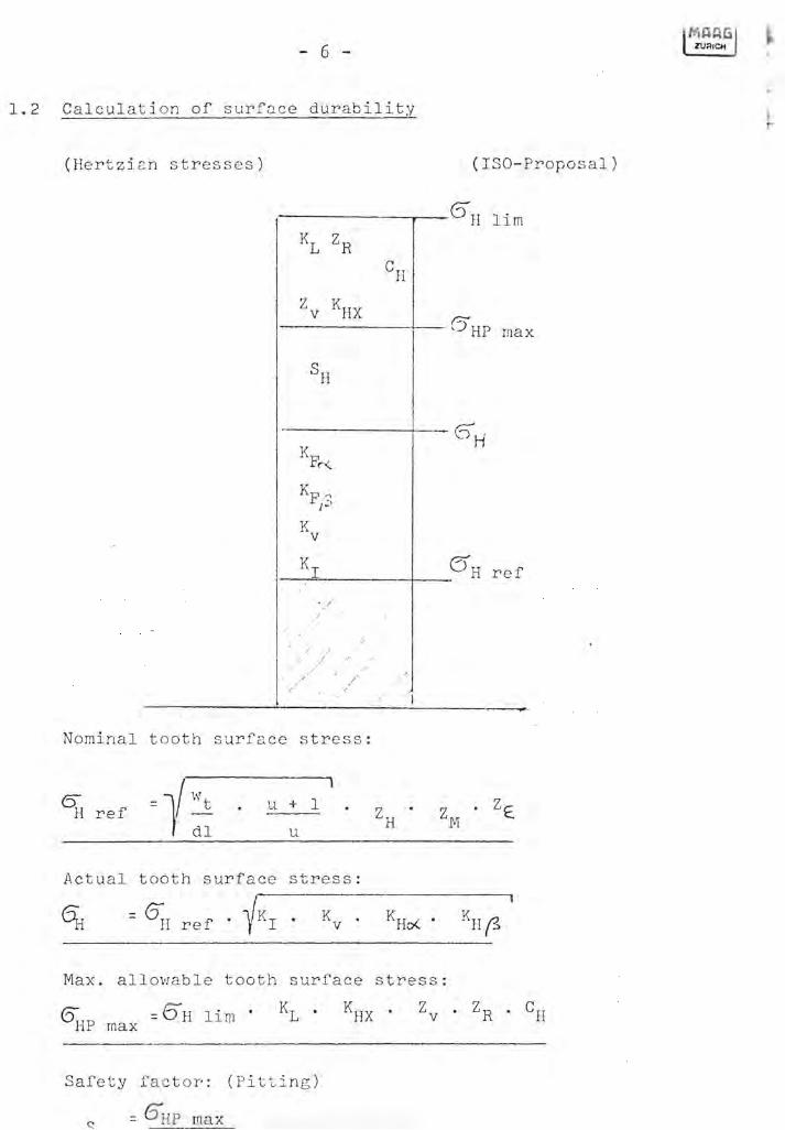
1.2 Calculati o n of surface durability
(Hertzi a n s tress e s) (ISO-Pro po s al)
6 H lim
KL ZR C
H
Z KHX v 0' -, H P max
SH
6 H K F, .. ,
Kp <' I~'
K v
KI (5 H r e f
. . /
/
/
"
/ " J " - I --
Nominal t ooth surfa ce s tre ss:
(5 H ref = 11 Wt
dl u
u + 1 Z . H
Z • ZE. M
Actual t ooth surface stre ss:
Max. allowabl e tooth surface stre s s:
Safety fac t or': (Pi t ting )
= 6 HP max

Symbols:
Wt
kp/mm
'0 m <'Il n 0 H d
l mm
u
YF YE l/~
rl Y(3
<'Il Ys ·rl >-. (1)
ZH .J-}
Cil
ZM 2:
ZE.
~p ~ .r1 Kr K
v
KFo( KHo(
~X ~ KL Z
v ZR' C
R CH C'(
CL
Cs
OF lim kp/mm U)
°H kp/rruTI .J-}
lim 0. ·rl E E
TB °c (1) ori lim .J-} rl
(/) SF H 0 SH .J-} C)
SB co <:,...;
2
2
- 7 -
Tooth load per mm of face vlid th
N orrna 1 module
Pinion pitch diameter
Speed ratio
Tooth form factor; ~~AG-Hb page 123
~= Contact ratio
Helix factor
Stress concentration factor
Tooth flank form factor
Material factor
Contact ratio factor
Longitudinal load distributior. factor
Overload factor
Dynamic factor
Transver s e load distribution factor
Size factor
Lubrication factor
Speed factor
Surface roughness factor
Hardness ratio factor
Lube oil factor (additive s )
Lube oil factor (viscosity)
Surface treatment factor
Tooth s trength, bending
Surface durability
Flash temperature limit
Safety factor, tooth bending
Safety factor, tooth surface
Safety factor, scoring

- 0 -
2. The MAAG method to predict the scoring resistance
The formulae are based on the theory by Prof. Blok on
the flash temperature which occurs at the contact points
of two tooth flanks when going through mesh. This
temperature is a criteria in predicting the danger of
scoring (2).
The highest temperatures occur at the tips of all the
pinion and gear teeth where the sliding speed is largest.
Experience also shows that it is at these pOints where
scoring takes place first. If the flash temperature exceeds
a certain level the oil film between the tooth flanks
evaporates and looses its capability to carry load. There
fore the factor "lube oil" has a big influence on the
scor ing limit.
As a point of reference the limit flash temperature has
been determined from experience and tests for a straight
mineml oil v.;rithout EP-additives, having a viscosity of
40
E / 500
C (30 cst / 500
C).
Furthermore, this limit temperature is valid tor newly
growld gears wi th a surface roughness of ""1 fm (25 finch).
TB lim = 1400
C
If for a particular case any of the above factors differ
from the values given, the limit flash temperature
TB l' is corrected accordingly by the respective C-factor lrn
to obtain the max. allowable flash temperature TBP max.
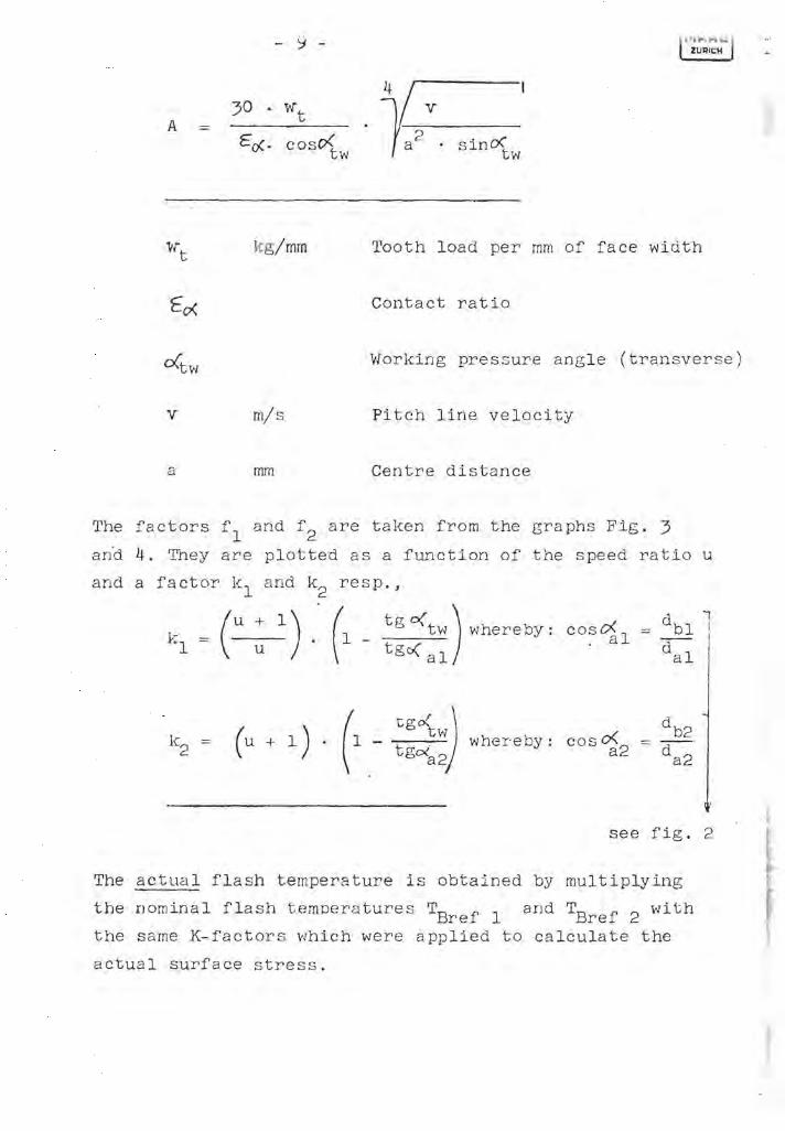
Calculation of the nominal flash temperature TB ref: ------------------------------------.------------.-------At the tooth tip of the pinion A
At the tooth tip of the gear T = A . f2 B ref 2
- 9 -
v A
Ed:- cos~w
kg/mm Tooth load per mm of face width
Contact ratio
Working pressure angle (transverse)
v m/s Pitch line velocity
a mm Centre distance
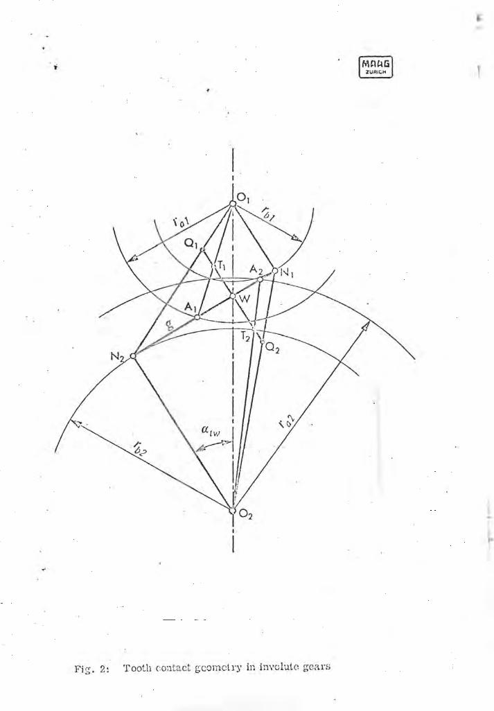
The factors fl and f2 are taken from the graphs Fig. 3
and 4. They are plotted as a function of the speed ratio u
and a factor kl and k2 resp.,
k = (u + 1) ." (1 _ tgc{tv~) vlhereby: 1 u tgo( al
coseXl
== dbl 1 "a -- i dal
tgoC J tw t · whereby: cos 0<2 g~2 a
see fig. 2
The actual flash temperature is obtained by multiplying
the nominal flash tempera tures TBref 1 and TBref 2 with
the same K-factors which were applied to calculate the
actual surface stress.
- ..Lv -
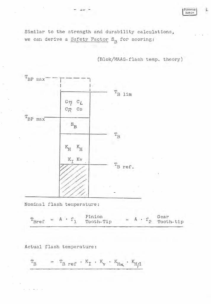
Similar to the strength and durability calculations,
we can derive a Sa fety Fa ctor SB for scoring:
(Blok/MAAG- fla sh temp. theory)
TBP max---r----I
I I
C"? CL CR Cs
T BP max
SB
~ ~
Kr Kv
/ / / /', /: //'
~ .<~/~ ./ /--.. .. / "
" ./ - "" .
Nominal flash temperature:
T Bref A . f
1 Pinion Tooth-Tip
Actual flash tempe rature:
TB lim
TB
T B ref.
A . f 2
Gear Tooth-tip

Max. allowabie fl a sh temperature:
T BP max
Safety factor (scoring)
T BP max
= T B
Comments:
As already mentioned, the calculation of the scoring
limit is relatively new, but from practical experience
a good deal is known today in this field. By comparing
these results with the calculated figures, we found that
the flash tempera ture theory is sound and a good
instrument to predict the scoring limit. Still:. the
various C-factors listed above are not yet known ade
quately. Until further facts are available we have
abandoned the idea of calculating a Safety factor. For
the time being we simply calculate the nominal flash
temperature TB ref multiplied by the overload f~ctor Kr For each gear app lication we know from practical experience
what flash temperatures are permissible to assure a sound
safety against scoring.
\'1i th growing villowledge and experience \'Je sha 11 eventually
be able to calculate with good accuracy a safety factor
SB as laid out on page 10.

3. The AG MA-Approach; Service Factor
AGMA has issued two standards for the rating of single
and double helical gear teeth:
1) Rating the strength of gear teeth: AGMA 221.02
2J Rating the surface durability of gear teeth: AGMA 211.02
These two standards contain the basic formulae for the cal
culation of the tooth bending stress and surface stress
(Hertzian stress). They also give allowable stresses for
various materials and hardness. These standards are
generally applicable throughout the gear industry as far
as helical teeth are concerned.
For a number of special gear applications standards are
available which reflect the individual design practice
in that particular field, e.g.
Rolling mill gears:
Speed reducers and increasers:
High speed gear units:
etc.
323.01
420.03
421. 06
These individual design practices are all based on the
standards 211.02 and 221.02.
3.1 The Service Factor
The service factor is best described in the AGf"lA Standard
Practice for High Speed Helical and Heringbone Gear Units,
AGMA ~21.06. It is a well defined factor and relates the

so called "rated horsepo'V'ler" to "Service horsepower".
For each mesh there are three factors to be calculated:
1. Service factor for tooth bending strength, one
for the pinion- and one for the gear-tooth:
horsepower rating strength )
service horsepower
2. Service factor for surface strength:
-
p ac
CSF := P sc
horsepower ratingjdurability ,I
service horsepower
This factor is the same for pinion and gear because the
surface stresses at the contact point of the two flanks
are always equal.
The lowest value of the three is the Service Factor of
the gear.
The horsepower rating:; P t and P are the max. allowable a ac powers to be transmitted hy the gear, based on tooth
strength and durability respectiveley. The strength
rating is calculated using the formula of AGMA 221.02,
the durability rating is derived from AG!11A 211.02. All
K- and C-factors are taken as unity except for:
Lo a d distribution factors K and C m m
These factors are derived from
Strength: K - AGMA 221. 02 m Table 2
Durability: C AGMA 211. 02 m Fig. 4, first red curve
- Dynamic factors K and C v v
Strength: K - AGMA 221. 02 Fig. 6 curve v
Durability: C - AGr-w. 211. 02 Fig. 6 curve v
The horsepower rating depends further on:
Gear dimensions
Speed ra tio
Tooth geometry and module
Material and surface hardness
2
3
By definition, the service horsepower is equal to the
maximum continuous horsepower capacity of the prime
mover. Therefore, it would be wrong if a buyer would
order a gear for a somewhat higher horsepower than
needed, "just to be on the safe side". This safety is
taken care off by the service factor~ AGMA 421.66,
table 3, recommends service factors for various gear
applications.
It is important to note that the Service Factor does
not include gear tooth accuracy at all~ The load dis
tribution factors K and C only depend on face width) m m
and the dynamic factors K and C are only a f\illction . v v
of peripheral speed. In actual fact, however, both
1..
factors are influenced to a great extent by tooth errors~
Therefore, the AGMA Service Factor is no criterion at
... ... ,:; ~
all for the quality of a gear; it only gives an indication
on the dimensions and the material strength of the
toothed parts.
. •

References :
(1) Tragf Eih igkei t sberecruJuI!g von
Stirn- und Kegelradern nach
DIN 3990
(2) Lubrication as a Gear Design
Factor
VDI-Z Band III, 1969, Nr. 4
Proceedings of the Inter
national Conference on
Gearing, London 1958
I ·
I
Fi:;. 2: Tooth contllct geometry in invdutc geRl"S

3,0
2,8
2,6
2,4
2.2
2,0
t; 1,8
(, 1,6 .\ .~ r 1,4
1,2
\0
O,a
0,6
0.4
--l~~ U .

~ 2,4 r--_.-l
2 . l .,.
0,4
f _ _.. f / ..
MOAti ZUR'Cfi
G 10


