Calibration of instruments measuring broadband and spectral solar (UV) irradiance Gregor Hülsen, Julian Gröbner and Luca Egli Physikalisch-Meteorologisches Observatorium Davos, World radiation Center (PMOD/WRC)
Transcript
Calibration of instruments measuring broadband and spectral solar (UV) irradiance
Gregor Hülsen,
Julian Gröbner and Luca Egli
Physikalisch-Meteorologisches Observatorium Davos, World radiation Center (PMOD/WRC)
PMOD/WRC
And is signatory of the Mutual Recognition Arrangement by the Committee
of Weights and Measures (CIPM MRA).
The PMOD/WRC is the World Radiation Center of the World Meteorological Organisation,
PMOD/WRC
PMOD/WRC
Absolute radiometry
(ARS)
Infrared radiometry
(IRS)
Optical depth
(WORCC)
UV radiometry
(WCC-UV)
World Radiation Center
2013
Outline
What is traceability?
Calibration and Quality Assurance of
Solar Spectroradiometers
Broadband Filter Radiometers
Uncertainty
Summary
Measuring solar (UV) irradiance
What do we want?
• Value of solar irradiance in Wm-2
Who guarantees that W is Watt and m is meter?
How confident can we be that this value is true ?
1) We need traceability to the International System of Units (SI).
2) We also need an Uncertainty and confidence level
Albedo Measurements: “x 2”
Traceability from a metrologist point of view
2.41 metrological traceability
property of a measurement result whereby the result can be related to a reference through a documented unbroken chain of calibrations, each contributing to the measurement uncertainty
International vocabulary of metrology (VIM), http://www.bipm.org/utils/common/documents/jcgm/JCGM_200_2012.pdf
from Traceability of measurement, ILAC-G2: 1994
Is this sufficient to be traceable??
Transfer Standard from NMI
Traceability from a metrologist point of view
2.41 metrological traceability
property of a measurement result whereby the result can be related to a reference through a documented unbroken chain of calibrations, each contributing to the measurement uncertainty
What it actually means:
(1) an unbroken chain of comparisons going back to stated references acceptable to the parties, usually a national or international standard;
(2) uncertainty of measurement; the uncertainty of measurement for each step in the traceability chain must be calculated or estimated according to agreed methods and must be stated so that an overall uncertainty for the whole chain may be calculated or estimated;
(3) documentation; each step in the chain must be performed according to documented and generally acknowledged procedures; the results must be recorded;
(4) competence; the laboratories or bodies performing one or more steps in the chain must supplyevidence for their technical competence (e.g. by demonstrating that they are accredited);
(5) reference to SI units; the chain of comparisons must, where possible, end at primary standards for the realisation of the SI units;
(6) calibration intervals; calibrations must be repeated at appropriate intervals; the length of these intervals will depend on a number of variables (e.g. uncertainty required, frequency of use, way of use, stability of the equipment).
from Traceability of measurement, ILAC-G2: 1994
Traceability chain for spectral irradiance Wm-2nm-1
Gröbner & Sperfeld, Metrologia, 2006
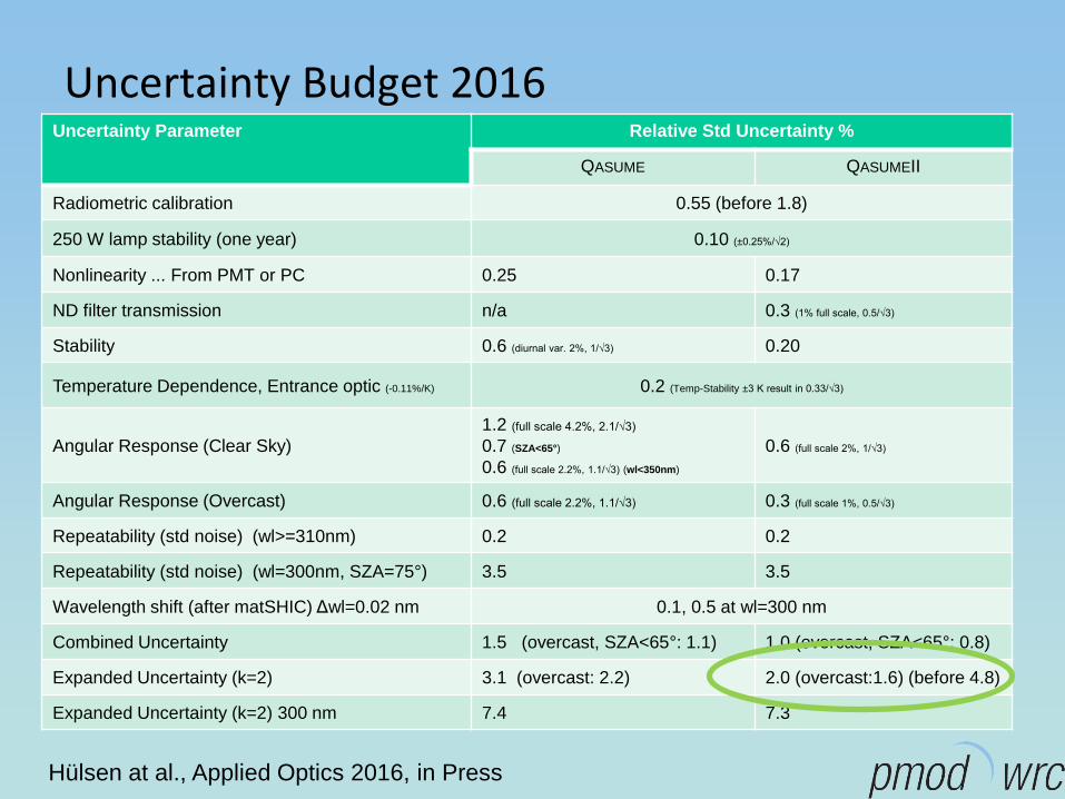
Hülsen at al., Applied Optics 2016, in Press
QASUME irradiance reference
Based on 7 transfer standards directly calibrated against the primary irradiance normal of
the Physikalisch-Technische Bundesanstalt (PTB), in Germany.
Primary standard PTB
Transfer standard
1000 W FEL lamp
Transfer standard
1000 W FEL lamp
Transfer standard
1000 W FEL lamp …
PTB
WCC-UV/QASUME 250 W portable lamp
250 W portable lamp
250 W portable lamp
…
Portable
QASUME
irradiance
reference
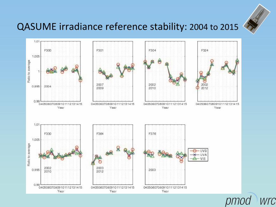
QASUME irradiance reference stability: 2004 to 2015
Validation of the QASUME irradiance reference at PTB
Blackbody BB3200pg at PTB
Tuneable Laser facility TULIP
QASUME Validations at PTB since 2004
±1%
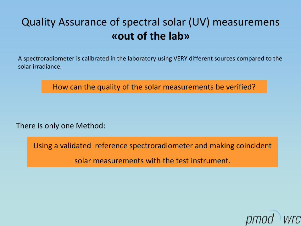
Quality Assurance of spectral solar (UV) measuremens«out of the lab»
A spectroradiometer is calibrated in the laboratory using VERY different sources compared to thesolar irradiance.
How can the quality of the solar measurements be verified?
There is only one Method:
Using a validated reference spectroradiometer and making coincident
solar measurements with the test instrument.
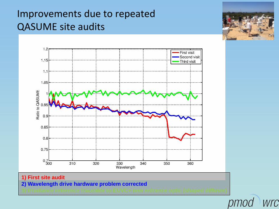
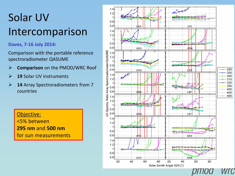
European UV Quality Assurance Program Quality Assurement through intercomparisons (since 2002)
and site visits of a designated reference instrument (QASUME)
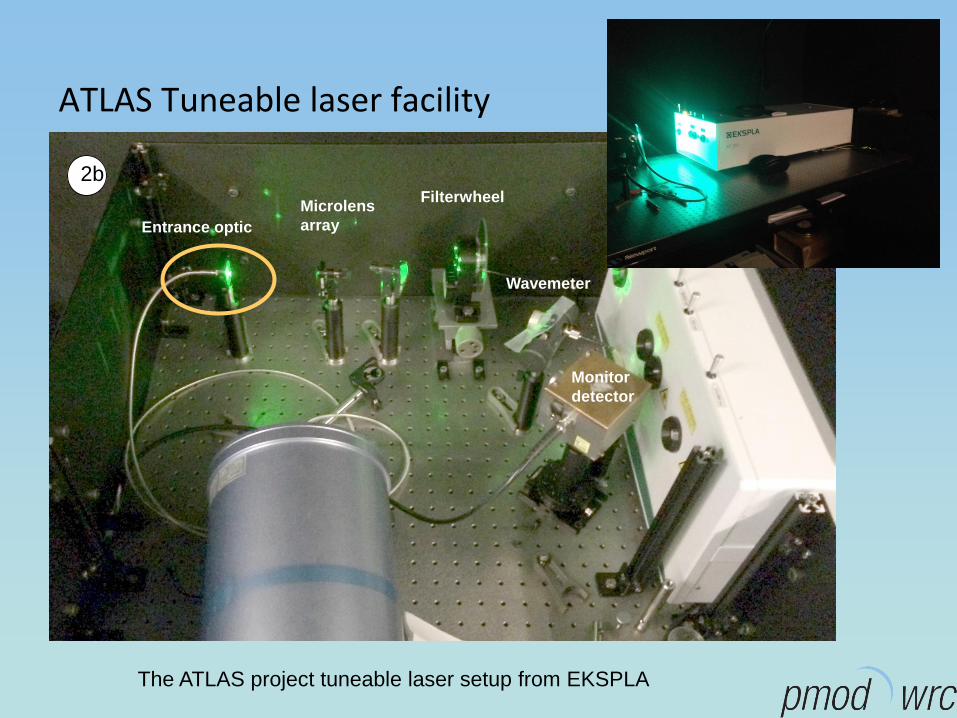
The ATLAS project tuneable laser setup from EKSPLA
Conversion Function f
dTOSZAESRF
dTOSZAECIETOSZAf
),,()(
),,()(),(
3rad
3rad
3
The function f converts from detector weighted solar irradiance to erythemal weighted irradiance using radiative transfer calculations:
Erad = Set of solar spectra calculated with a radiative transfer modelCIE = Erythemal Action Spectrum
2
f is normalised at SZA = 40 and TO3 = 300)
Remark: Albedo Measurements
EradDownwelling(λ) = const * Erad
Upwelling(λ)
f Downwelling = f Upwelling
If the Conversion Function fn is not used
Solar Light
Kipp&Zonen
15%
10%
YES
6%
CoscorTOSZAfCUUE noffsetCIE ),()( 3
2
Remark:
Albedo Measurements performed at high SZA
(Winter, Arctic, Antarctic…)
fn variability high
The Angular Response Facility
Xe-lamp
1000 W
Radiometer
BaffleWG305 filter
Shutter
4 characterised planes
Normalisation at normal incidence
Alignment precision: < 0.1°
Homogeneity of the light in the 25×25×25mm3 cube
around the centre of the radiometer: < ± 1%
3
Angular Response Function of various Instrument types with Cosine Diffusers
The expanded relative uncertainty (k = 2):
Less than 4 % for zenith angles smaller 80°
Cosine error = Deviation from ideal cosine response
3
Input Optic for UVVISIR
1) Diffuser Material become transparent for longer wavelength
2) Integrating spheres
Remark:
Albedo Measurements performed at high SZA
(Winter, Arctic, Antarctic…)
Cosine Error large
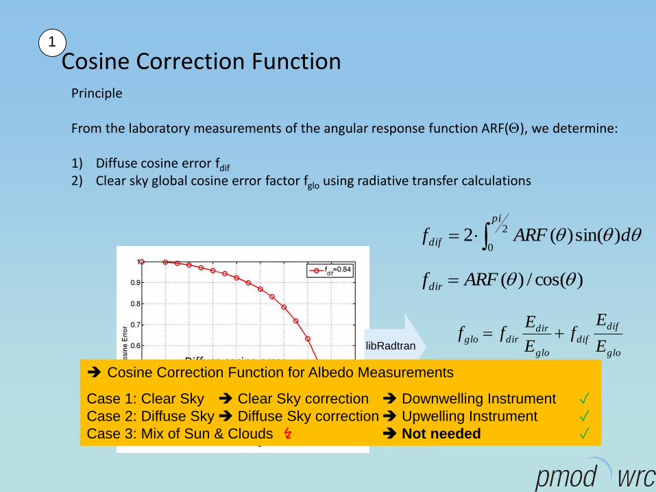
Cosine Correction FunctionPrinciple
From the laboratory measurements of the angular response function ARF(), we determine:
1) Diffuse cosine error fdif
2) Clear sky global cosine error factor fglo using radiative transfer calculations
glo
dif
dif
glo
dirdirglo
E
Ef
E
Eff
2
0)sin()(2
pi
dif dARFf
Diffuse cosine errorfdif=0.84
libRadtran
)cos(/)( ARFfdir
1
Cosine Correction Function
Case 1: Clear Sky Clear Sky correction ✓
Case 2: Diffuse Sky Diffuse Sky correction ✓
Case 3: Mix of Sun & Clouds ↯
Cosine Correction Function for Albedo Measurements
Case 1: Clear Sky Clear Sky correction Downwelling Instrument ✓
Case 2: Diffuse Sky Diffuse Sky correction Upwelling Instrument ✓
Case 3: Mix of Sun & Clouds ↯ Not needed ✓
Calibration of a Spectroradiometer for global (UV) irradiance measurements
• Angular response of entrance optic (diffuser)
• Spectral responsivity
• Wavelength dispersion relation
• Spectral resolution
• Temperature dependence
• Linearity
• Long-term stability
• Straylight from other wavelength with higher intensities (e.g. VIS and IR)
• …
• …
Calibration of a Spectroradiometer for global (UV) irradiance measurements
• Angular response of entrance optic (diffuser)
• Spectral responsivity (Lamp Calibration)
• Wavelength dispersion relation
• Linearity
• Straylight from other wavelength with higher intensities (e.g. VIS and IR)
• Spectral resolution
• Temperature dependenceLong-term stability
• …
• …
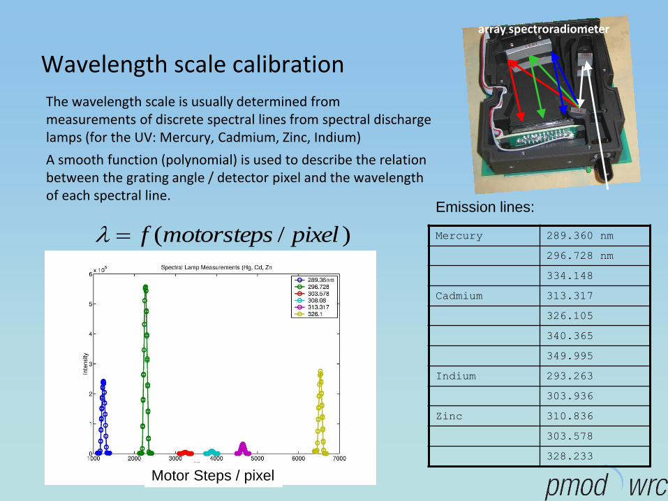
Wavelength scale calibration
The wavelength scale is usually determined from measurements of discrete spectral lines from spectral discharge lamps (for the UV: Mercury, Cadmium, Zinc, Indium)
A smooth function (polynomial) is used to describe the relation between the grating angle / detector pixel and the wavelength of each spectral line.
Mercury 289.360 nm
296.728 nm
334.148
Cadmium 313.317
326.105
340.365
349.995
Indium 293.263
303.936
Zinc 310.836
303.578
328.233
Emission lines:
)/( pixelstepsmotorf
Motor Steps / pixel
array spectroradiometer
Spectral wavelength error relative to the Fraunhofer lines of the solar spectrum
0.1nm
0.1nm
0.3nm 0.04nm
Stray light correction
• For array spectroradiometer
• Stray-Light correction using tuneable laser setup
• In-range and out-range correction
• Factor 10 improvement of spectral solar UV irradiance measurements
Line-Spread functions of arrayspectroradiometer
Solar Spectrum without (red) and with (green) stray light correction applied