RD-A53 677 WATERJET PROPULSION SYSTEM PERFORMANCE IN A MANNED 1/1 TESTCRRFT IN CALM WATER(U) STEVENS INST OF TECH HOBOKEN NJ DAVIDSON LAB D LUEDERS ET AL. MAR 85 UNCLRSSIFIED SIT-DL-85-9-2519 N888i4-83-C-0780 F/G 13/1@ NL E~hhhhEEmhhmhI ElEliIE~lllllI l'-.lllll
Transcript
RD-A53 677 WATERJET PROPULSION SYSTEM PERFORMANCE IN A MANNED 1/1TESTCRRFT IN CALM WATER(U) STEVENS INST OF TECH HOBOKENNJ DAVIDSON LAB D LUEDERS ET AL. MAR 85
Approved for public release: Distribution unlimited
17. DISTRIBUTION STATEMENT (of the abstract entered In Block 20. If different traim Report)
ISI. SUPPLEMENTARY NOTES
19. KEY WORDS (Continue on revre aide it necessary and Identity by block number)
Waterjet PropulsionAmphibian
20. ABSTRACT (Continueaon reersea old@ It necaesary and Identity by block number)
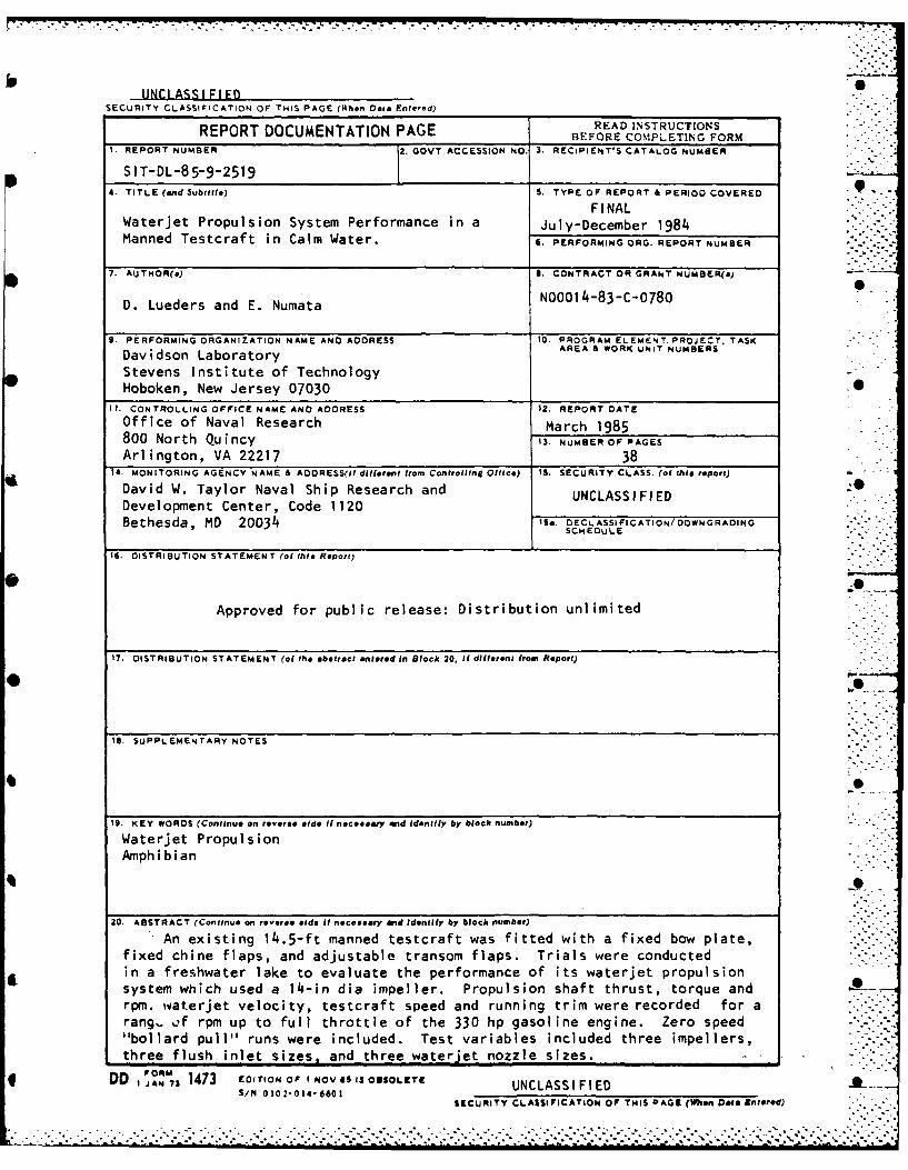
An existing 14.5-ft manned testcraft was fitted with a fixed bow plate,fixed chine flaps, and adjustable transom flaps. Trials were conductedin a freshwater lake to evaluate the performance of its waterjet propulsionsystem which used a 14-in dia impeller. Propulsion shaft thrust, torque andrpm. waterjet velocity, testcraft speed and running trim were recorded for arang-. o.f rpm up to full throttle of the 330 hp gasoline engine. Zero speed"bollard pull" runs were included. Test variables included three impellers,three flush inlet sizes, and three waterjet nozzle sizes.
* DD 1JANm73 1473 EDITION OF INOV 69 13O2SOLEITE NLSSFE
SECuNiTY CLASSIFICATION Of THIS PAG9 (ften Data Entered)
a'. . C'-j ' 0 2 N0 - LA, 0 G. 0D . - Ncc In V% a, In LA LA o 0
- n N N m 10 N .
N N N
~~~'.VC ~ 0.' N. a' ' ' ' '- . 2 0 2 C
CL - N - 00 N N C'n t- N N \N
C)m
a)~ ~~~~ 0 Nn 0 A 0 A * * - ' '- 0 C@~~ ~~ ~~~~~~ N . ' ' N '0 ' ' A N-- - C'
C. C'3 -0 a, NC N *7 a, .LN 0 " (a - - N
a, C'- N' N, LA 0 C- . L 2 0. 10 LA 0 L c"a LA 0 0 _ ;2 'o m LA .2 m t- N
L0 In CO 0 a, co I I I
NJ -02 a'1 t N - 10- N - D LA N0 LA m' LAm-,j) a, r- LA2 NM m '0 0 Nc 0 0 (" LA LA
0
"IC"~0 0- '0 "'a 1 0 a C- L1- ' 0 00 No 0 CaC~a 0 0' m ' C" C'- 02 a Ca 02 LA CaOL
r I
- - N N
116 a
R-2519
00t
in co z " 0 1
o m t0 0Z 0 c ~ . 0 0 0 t
C Y.C. C. C. C ~ C. C. C. C. C. C. C. C. C. C.-
o 0 0 0 0 0 0 ~~0 0 0 0 0 0 0 0 0 0 p
RIO
S C' ~. c-
o~I '0 0 0- - U; C;~0 ~PA2n~' cNlu '. -. : I
cU 0 o o C ; 4
I-.In
c4 '; 6 o N Z A s 17N Pi
R-2519
C) 0 0 '0 '0 '0 0 a- C) N- 4. a0 00 ' 1 4
o0 0 0 0 0 0 0 0 0 0 0 0 4~"
o0 (7 0 0 0c 0000 0
w N -0.
'0 a '0 N7 N 0Y C'~ '0 4.. . 0 '
r) - '30 c0 t- 0 Go c0 '0 N '. . 0 '0. .' '0 0
4) (: 09 U4. -9 '9 0' '0 L 0 90 4( ( ' 0 . '
CC ... G
4) - t0 00 00 ?- w. 0 0 U. . .4 0 '
-40 00000 0 0 0 0 0 0 0 0 0 -~- 0 0 U' 0 0 0 0 0 - .m C4 U 4 '0 i- - NI U'. '0 N~ 10 0 ' ' -N~ N . N
4).. 0 '0 t- '0 0 N- ' 10 N- - N 0' 0 70 4L I.. CL '0 U'. '0 N- N- '0 V. N - 4' N 0 '4 4
L0.
U( U' N - In4 u'. '0, 0 t- - CD 0 t .. ' )
C, I kn N 4 4 I I
o U',
'. NCN
0wcc a.dc'U-3 IV
CLW4
0416
-~ -' -. -- .--. • . •.
R-2519
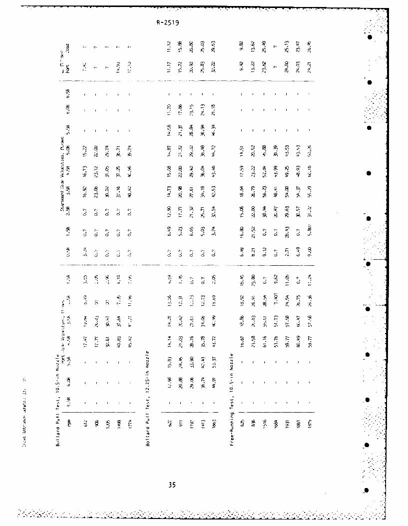
WATERJET VELOCITIES
In any run for which one or more zero velocity readings are listed, .0
these readings have been included in the integration for flow rate, provided .
that the total annular area involved is equal to or less than 14 percent of '.. - -
the nozzle exit area. For example, on Page 21 the test run at 5.35 mph -: -*
shows zero velocities at 0.5-inch and 1.5-inch radius locations on the
starboard side. The total area is that for a circle of 2-inch radius or
0.0873 square feet. Since this is only 11 percent of the 12.25-inch
diameter nozzle area of 0.818 square feet, the zero velocities were included
in the flow rate integration.
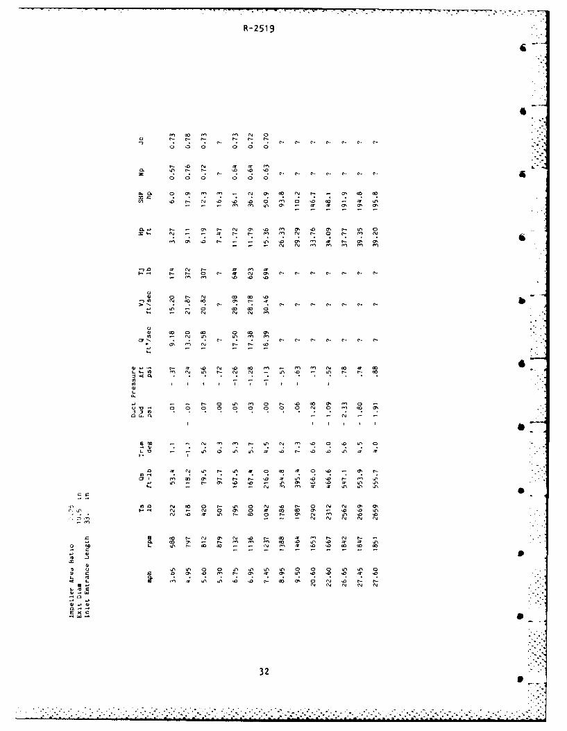
However, if zero readings are associated with a total annular area
equal to or greater than 15 percent of the nozzle exit area, an integration
of the velocities over the remaining area would yield an unacceptable
underestimate of flow rate. In such cases, a question mark had been :0
inserted in place of a flow rate. If for example, a port side flow rate is
reported but question mark appears in place of the corresponding starboard
side rate, the average rate would be taken equal to the reported port side
flow rate. If both port and starboard rates are in question, no flow rate .
is listed and all quantities derived from flow rate are replaced by question
marks.
0
15.
S '.- :
R-2519
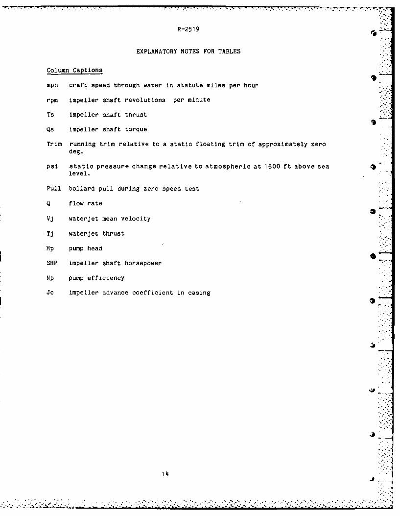
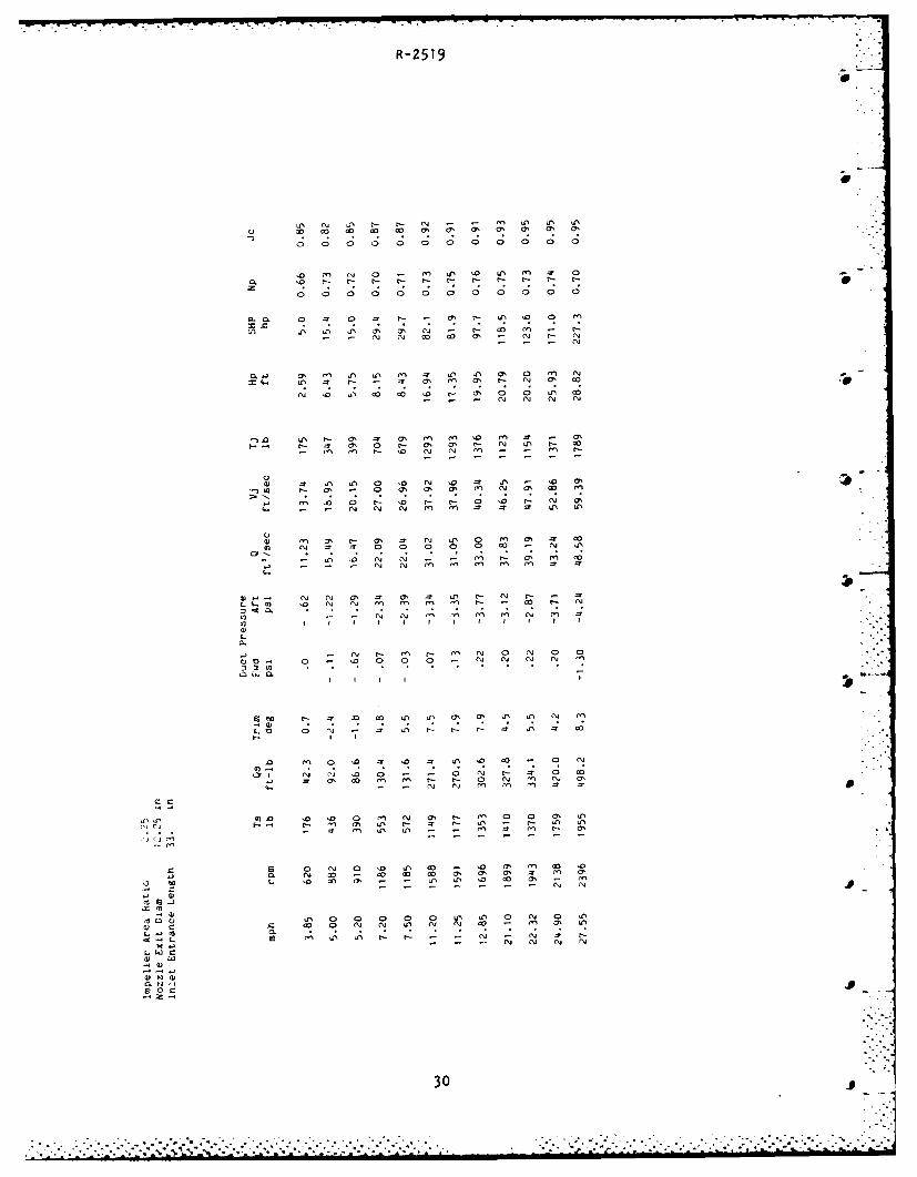
EXPLANATORY NOTES FOR TABLES
Column CaptionsIt
mph craft speed through water in statute miles per hour
rpm impeller shaft revolutions per minute
Ts impeller shaft thrust
Qs impeller shaft torque
Trim running trim relative to a static floating trim of approximately zerodeg.
psi static pressure change relative to atmospheric at 1500 ft above sea r#level.
Pull bollard pull during zero speed test
Q flow rate
Vj waterjet mean velocity
Tj waterjet thrust
Hp pump head
SHP impeller shaft horsepower
Np pump efficiency
Jc impeller advance coefficient in casing
14
J .
r - -
R-2519
An inclinometer was installed parallel to the craft baseline to sense
change in trim from a static floating datum.
A Dillon mechanical load cell with a 5000 lb capacity and a dial
indicator resolvable to 50 lb, was used to measure bollard pull.
DATA LOGGER
The de voltage output of each of 24 transducers was passed through a
buffer to compensate for any zero offset and to provide a measure of time •
averaging of the signal. The signal was then input to a data logger (Doric
Digitrend 210) which digitized, stored, and then printed a digital output on
paper tape. A sequential printing of 24 channels took about 20 seconds.
The logger was usually programmed to start a sequential printout upon
pushbuttom command and then stop automatically after the 24th channel output
was printed. The vehicle driver started the data logger by pushing on a
button protruding from the front of the instrument box, Figure 1.
13
7• . - -
R-2519
APPENDIX B
INSTRUMENTATION DETAILS
ELECTRIC POWER
A 12 volt engine battery energized a ±15 volt power supply dedicated
to all instrumentation.
TORQUE THRUST DYNAMOMETER
A transmission-type dynamometer was designed and constructed by
Specialty Measurements, Inc. with ratings of 5000 lb of thrust, 600 ft-lb of
torque and maximum speed of 4000 rpm. Builder's calibrations were confirmed
by performing static thrust and torque loads in the Davidson Laboratory
instrument shop; shunt resistances were used as calibration signals during
the trials. A magnetic speed pickup was built into the dynamometer and its
frequency output was converted to a dc voltage.
OTHER TRANSDUCERS
A pressure transducer of the "wet-wet differential" type (Schaevitz
P-3000 Series) was coupled to a Prandtl tube to furnish a voltage output
proportional to the difference between static head and total head sensed by
the Prandtl tube. Sixteen Prandtl tube/transducer sets were used to obtain
up to 16 fluid velocity readings across the horizontal centerline plane of
impeller discharge flow; transducer ratings of 15 psi or 50 psi were used
depending on the Prandtl tube location.
Two 15 psi transducers were connected to static pressure taps in the
inlet duct ahead of the impeller. A total head tube, attached to the port
rudder and projecting ahead of the leading edge of the rudder, was connected
to a 15 psi transducer to sense craft speed. All pressure transducers were ' -
bench calibrated before the trials and check calibrations were performed
during the trial. Prandtl tube/transducer units were towed in a model basin
to check their inherent calibrations.
12
S _.= !
. . . . . . ..".""'. . .." " " ' "*..-- .. . .
R-25194 -
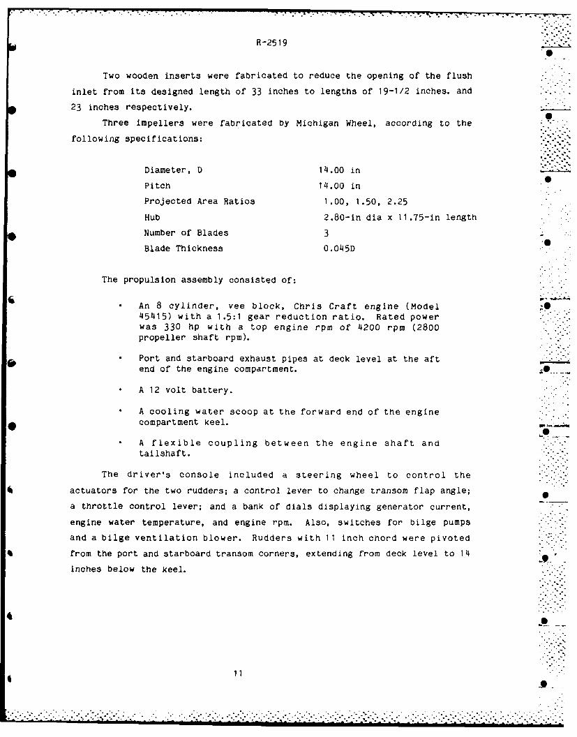
Two wooden inserts were fabricated to reduce the opening of the flush
inlet from its designed length of 33 inches to lengths of 19-1/2 inches. and
23 inches respectively.
Three impellers were fabricated by Michigan Wheel, according to the
following specifications:
Diameter, D 14.o0 in.0
Pitch 14.00 in
Projected Area Ratios 1.00, 1.50, 2.25
Hub 2.80-in dia x 11.75-in length
Number of Blades 3
Blade Thickness 0.045D i
The propulsion assembly consisted of:
An 8 cylinder, vee block, Chris Craft engine (Model .45415) with a 1.5:1 gear reduction ratio. Rated powerwas 330 hp with a top engine rpm of 4200 rpm (2800propeller shaft rpm).
* Port and starboard exhaust pipes at deck level at the aftend of the engine compartment. 0
* A 12 volt battery.
* A cooling water scoop at the forward end of the enginecompartment keel.
A flexible coupling between the engine shaft andtailshaft.
The driver's console included a steering wheel to control the
actuators for the two rudders; a control lever to change transom flap angle;
a throttle control lever; and a bank of dials displaying generator current,
engine water temperature, and engine rpm. Also, switches for bilge pumps
and a bilge ventilation blower. Rudders with 11 inch chord were pivoted
from the port and starboard transom corners, extending from deck level to 14
inches below the keel.
11".
R-2519
APPENDIX A
TESTCRAFT DESCRIPTION
The testoraft hull, Figure 1, was configured to represent a 0.55-scale
model of a proposed high-speed amphibian, "Tack Hammer". For convenience of
construction and assembly, the hull consisted of three units:
A bow section with a "bow plate" constructed of aluminumalloy plate attached to the hull bow with hinged tierods.
An engine compartment containing the engine assembly andthe driver's console.
A pump box containing the waterjet inlet,, pump impellerand casing, gasoline storage tank, rudders and rudderactuators transom flaps and flap actuators, and driver'scockpit.
A boat trailer, dedicated to the testcraft, permitted the testcraft to
be launched from any recreational boat marina ramp.
The waterjet system consisted of:
A flush inlet in the form of a 33 inch-long by 14.12 inchwidth rectangle.
A transition duct with a 17.06 inch height by 14.12 inchwidth rectangular inlet and a 14.12 inch circular outlet.
A 14.12 inch I.D. by 3 inch long cylinder in which werehoused four equally spaced radial struts supporting ashaft bearing housing. 9
A 14.12 inch I.D. cylindrical casing which housed a 14inch diameter impeller.
A nozzle with an inlet/discharge area ratio of 1.8/1;an alternate nozzle of the same length with an area ratio1.33/1; exit diameters were 10.5 inches and 12.25 inches,respectively.
The bearing support ring, struts and bearing housing were constructed
of aluminum alloy; the impeller was manganese bronze. Inlet, transition,
casing and nozzles were molded of fiberglass/polyester resin laminate.
10
............... ......... ...... . . . . . .
R-2519
REFERENCES
I. Numata, E., "Performance Trial of a Manned Waterjet Testcraft", Davidson I
Laboratory Report 2390, March 1984.
I
2. Roper, J.K. "Design Procedure for Low Speed Waterjets Suitable for
Application in Amphibious Vehicles", Davidson Laboratory Report 2518,
November 1984.
(0I
9I
9 -
4. 'I
.........................
R-2519
~a UN C7% cy% a' rJ 0 -~ N 7., U, en 0
4a p c3 oN t-0 '0 U - a' (N 'o 0 0 o \o, u) ja N cla N4 'n In ~ ~ .~
w-. an, C- CO, a't - lo cl- a' n0 - a' a - - a N e N 0 N a
c, a. o 0t0 ) - a' en C- 3
In In
a~~ e en C 0 a' a uN o a' ;- I n
o (a n a ~- - ' n cc a, -n r4 UN r- I N N N en mn e e
S a' c) 0 0 N Un a' WN C- '0 c'.- Os a
at' C- c- N.- N a, c- oN '0 - D~
Ln - 0 D0 D0 en, en a' - 0e eN (" (N en e n m uN X% U u%
a,~ O o - r L n c- an D C- 01 a' C- UN
.0 C- N ~ m0 rn m Ln u"%0 N ~ C- a
c.m N ac 0o m 0 '0 en en co a en C- - e
N-U C- N7 C- C-j en N- -zNN a N 0 ~ O
S - N N N en eN en In m _r at U
4)UNC~ enj an rl en CI-~ - a n - N a
ren o- U) ato -N CO -W N UN 0 0
c2 '0 en U N ' a 0 N an Ccj - ano co
040 0m C- I n a n 0 N '0 -- .r~
t- o\ -o N' 04 N N en en enN
UN UN rl en- N In r-- ON Crn a - C n 'a' ~ '4 N In en UN In 0' 0 - e
co N ~ N L wN \Q -' Ln m en n
0 "I a, as \j en N n 0~ n en 0 D- ' anN N- In In - N n e
0 0 '0 '9 N 0 n n U- N (N N n en -l N N N (N
-n 2 N eo n en en. en en -
.
.UN 0- '0 mN 0 c n C N e 0 oN C
I' C n co IQ -D en C- N N 0 '0D4) - N N en In en en e
lo mUNa)NC r
-N ('NU 0 ) o LA C- o C-uC - * n 0 N
aaU N 0 0 ' n e - - N ' L
o c m -~~~~ '0 -e C N N - e n a
'0 0 C- - - - 0 - '0 - '0 0 C- '0-
R-251 9
cr , (yl r-- N (4 N (( 1 0 0 5 a, In ( 0 (O C, '0 0a, C, 0.1 a, 1: t- 19 .09 (A (A ' 19.0
o0 0 0 0 C0 0 0 0 0 0 0 0 0 0 0 0
0. o0 5 . - a, - 0 5 N (A ZW c N -r N .0 %0
o o 0 0 0 0 0 0 0 0 0 0 0 0 0 0 0
(A (A ( a 0 t-- (A lo N e o I" z5 0 r- 0
Mr.- 0 (A '0 (A, a, in co cn en 0o N0N e N
-m Nf N e n en Mn m en
of a, 0n '00 (A N (A a, N 0 0 N , m'
('J S a, O- 0 - - N S N .
- 0 - C. ~eI- ( N cm A 0 (A N 0 '
c9 5 0 a, - (A .0 c9 (A '.0 0.0 0 n (1
N - n n ( - .- - n mn fn en en S
0~ (A C-- en -- .0 '4 ~ ( a, 0 n rn 2 "1' a
I ( C- O\ CC 0 ' N a- 0 - '0 ' 0 - S (- . - N '4 Mn S~ - - N N
v- - ' (4 "C e N N N N~ N N - ( N1 7 I I I ml I I I I 1 7 -1 T( I
L
I -A o, m 0o Ln -7 un ' A S a A'0 W
a N CD -or- o 7 o E -r a- N 1.
'4 o o In 0 '-N o
c2 o en .- m 0 N Nv '0 lo _r o0 (ALO~~~ .- N (C- wC ' 0 C- 0 - - C- 0 C. C. S S (
711 5 C 0 0 'C S A DC. N en a,- '0A 'a3 5 , a ' A en e ( a, '0 '0 (A N
oCf C-- o- on o0 0 I0n N In N (A ' 0 , ~ -
N N N N~ N
C G -- N 0 (A -0 N ('I S - ("C , ( C-L In o - ' a , 0 ( 0
L. C 0 ' 0 . A ' 0 0 ' 0 ' 0
- - - 24
R-2519
"co N .
S - -q s mt
s O N N m 19 A 9A
* Sp
co '0 0'
0 C-0 ('0' 0 -
c2 Fm 'o Pk 's 01 8 A m -7 '
- ~ ~ ~ ~ ~ ~ u .- . .- 4: 0 0 0 0 0 N '
090
25 ~0' 0 . '. '
R-2519
N I W3 03 a' El a - N rs mo CL 3 '3 ' 3 ' 3 3 ' 3 '
a 0 0 0 0 0 0 0 0 0 0
ot 03 0o 0D m N c-
Q6 u6N N C- C- 3 3 0
o a, lo ' m N N '~~' '3 o- N C- 4 - t t
'3 nj cc o- o- a' m '73 o-
- N .tS OS C- '3 C- C- c.- m3 It
- l If, Nn '3 G' N' ' 0
L .- - a, (In No N C- - 5 -
:3 d 3 0 5 3 a C- . C- CS N6
71 - - TS US a 'o "I US - USl 'lo '3o US
C-S ~ ~ ' 05 o.I ~ U - N ' -
-w o. N; C-9 C- -S CS -L S L -. o t- ou
a, JUS ~ ~ .C- . '4- 0 a' '3 O-
#) D N -T lS O N ~ uS
*o a, o S o c-S Q . 3 U
La o C) 0 US US ' .. 3 C- C 3a --
UN) c. . . S . . S
U, o-
061' - 3 ' 3 CS ao 4 . ' f ( - ** N 0 C- '
S..- - N N
413C-S * N C-- * N * - C-S26U
R-2519
0*1 z0
m 00
A 5
'0.
ej WN:: = : i !
C3 C'J C '0
C'.. Cl.C
b MU A a
- ('4 ('J'.J ~In
z-
10 a
27
R-2519
r" IA <\ c0 W0 O0 t- t-- co c0 '0 in UN LM co 0'o ' '0. 0' '9 '9 09 C9 09 09 09 09 '0 '0 '0 e-; 11
o 0 0 0 0 0 0 0 0 0 0 0 0 0 0 C0
o 0 0 0 C) 0 0 0 0 C) 0 0 0 a) 0 0
a. 0 O ) '9 C) 0' 0' 0% '0 - 0 N - -
a,''0 0 0' % 0 N N ''4 N * *- * * C'- '0 m' . - N N N *
0..- 0' N IA m 'D CO N U'% N N 0 '0 "
a. C'- 0 9 '0 '0 0' '0: 0 t ' C.
fl c0 '0 <\ r.- '.0 Nq 07' ' N L- W- I0C- 0' N '0
E-'' '0 m' 0 N0 t UN m -n m0 0 0 _'r c'- '0 L-* C%- C ' ' C C) C) -9 - C
'- 0 - .D U- I '0 C, L- t'- L- W0 W- q N q N v NM" '~ m M~ C' m M' mI
IAv ;- N C t, c'- M0 %I 0 fnI mI 0' No ' N@y 0' 0 C) CA C ' 0 I ' 0 C- C-C I
- 0 N '0 co a, a, IA a' 0 ) C
-,*- N 0 M CIn Nn Nr -r NM ' 0 - - 0
L~..M IAi N 0 C'- ' - 0 ' 0 C I
L X
In a 0' Q CO -0 a, 0' 0I '0 '01 M A
mY O M o 1..
LO N0 a, I I n '. 0 0 C ' '0 C'- '0 Cl- C- '0 C'-
0 on C- 0 *Y '0 I . - N 0 0- W
CCI IA '0 ' C N " A '0 '0 o, a, 0' 0' 0-- N N N N N N N N N MC .
.71 No C * '0 C- '0 a, InI Ny '0 N 0) 0 0'1 0' N'I.-~~U -- ' '0 A C' 0 U'% 1AA O ) 0 '0 '0w
- N 1C 0 '0 '0 '0 0 ) C -
o o) - '0 N 0A t-- 'n m-- '0 o 0 0
0 U L. . 0 0 60 IA ' 0 0 0 N3 N) 0 N N
a 0-C 0. o
~ LS '. 0 '0 '0 '1 )' A 0 I I I '0 '028
R-2519 -
A A.
100
a~, coS
t; I
8~In #1~
P! S 8In~m1c In*~;
0"4 f -9 4M ~
10 10Fi F
9 8 S An V !6
??00
129
R-2519
C)~~~~ '0 '0 aO '0 0' 3 ' 3' 3
Q 0 0 0 0 0 0 0 0 0 0
'0N N- oo 0y N-m L 0 L
0-o0 0 t - -y 3' C- LA ' 0 t
4-.. N' m~ mA LA1 _r~ =r u,\ LA 3 0
LA) m' a,'7 N '0 oc
-N -. .- NN
-,f L C 3 ~ 3' C- ' m GO . 3
I~ C ~ 3 0 C 3' ' C- N LA C- '
-QL' ~ . - r2 C
o
LCL
0'-..LA . N N - - -i C 3' -i o
a m
n No 10 c-i t-m N 0
o o
k ~ r 01 N U L C- C - A ~ '
I-. I
zl C- 0 C0: A ~ '
.. .. .. .. .. .. .. .. .. .. .
R-2519
I II I I II In
Rd . . 0 .
II)n 'A -4
Pj~~ ~ ~ ~ %I" 9 R 4 .
CCJJ7
2-
31m ~
-~L7,
R-2519
m, '3 m C~ N 0
0 C C) 0. 0- 0- 0.
-,. I'C. C.. I'. I.. Cl. . C.o 0 0 0 0 0
a - '3, \9 19
0. - aC- C. 3 ' '3
Z- .c.. N. c.. '. C.. cl. .oD 0o 0 0 0 o
C/C .0 C.- N co co '3 0 Clo 3 '3 - U
~~~~ N N fn- C ~ . 0 C ~
lo N lo co In w ,
L CC, '3 '9.
ul N ' '3 a - -
~~~)~ '3 0 '3 0 '3 a
C.. C.. C. .. C. C .
L v ' 7C 'n o .u - ' o3o 'D
ta.. In- o N3 No '3- o3 CC4 N- Cy, (71NN~.a CC o N , N N -o In' , - - '
IQ C2 T C C
L M- 1 . n IQ 0D a% C) 0~ C.o '3 '3 a'
o N. N.- . N .- -
L ',D CcC , N CC 3 0 ' r
-'32
R-2519
SC.- 8C . C C. C. C. . ..
g, F, C- m C-
C' 0
8 Gi I 9I
0: C.. CC. 0
-J , 0. 00 00 0
: g 0.;C. C . C C.: I; I; C.:a C C-~ 0~l C 0 0 0 0 0 0, 0