36
Care and Feeding of Your CNC Router Darrell Norquay 3D Tech Works

Care and Feeding of
Your CNC Router
Darrell Norquay
3D Tech Works

Important Safety Considerations
Warning! All power tools are inherently dangerous and there is always the risk of injury due to improper use. Be sure to read,
understand, and follow all safety guidelines supplied with your equipment, and always use proper protective gear,
especially Safety Glasses, Hearing Protection, and Dust Mask when operating this equipment. Save this document for
future reference.
Work Area
• Keep your work area clean, well lit, and free of debris at all times. Debris can cause slips, falls, or be caught in
the machine and cause injury.
• Do not operate electrical or power equipment in explosive atmospheres, such as in the presence of flammable
vapors, liquids, or dust. Power tools can create sparks which may ignite flammable vapors or dusts
• Keep bystanders, children, or pets away from the area while operating. Distractions may cause injury.
Electrical Safety
• Double insulated tools are equipped with a polarized plug, which fits in the socket only one way. Do not alter
the plug to defeat this feature. Tools equipped with a 3 prong plug must be plugged into a grounded outlet.
Unmodified plugs and matching outlets will reduce the risk of electric shock
• Avoid contact with grounded appliances, water pipes, radiators, standing water, etc. while working with the
machine. This will lessen the likelihood of electric shock
• Don’t expose machinery to rain or wet conditions. Besides the possibility of damage to the equipment, water
exposure will increase the risk of electric shock.
• Do not abuse or modify the power cord or plug in any way. Do not try to defeat the polarization feature or
remove the grounding pin. Any modification to the cord or plug could cause lethal electric shock during
operation.
• Keep cords away from heat, oil, sharp edges, and moving parts to prevent damage. Repair or replace any
damaged cords before using equipment. Damaged cords increase the likelihood of electric shock
• Use of a properly functioning GFCI circuit is always recommended for power tools. GFCI circuits reduce the risk
of electric shock should a fault occur
• Always connect the machine to the recommended power source(s), with the proper voltage and current
capabilities as specified by the manufacturer. Failure to follow manufacturer’s recommendations may result in
damage or personal injury.
Personal Safety
• Stay alert, watch what you are doing, and use common sense when operating the machine. Do not use if tired
or under the influence of drugs, alcohol, or medication that may affect your judgement. A moment of
inattention may cause serious injury.
• Dress properly. Do not wear loose clothing or jewelry. Keep long hair tied back. Use caution when wearing
gloves as they may increase the possibility of entanglement. Loose clothing, jewelry, or long hair may become
entangled in powered machinery causing injury
• Avoid accidental starting. Ensure switches are off before plugging in. Plugging equipment in with the power
switch on may cause injury

• Remove any adjusting keys or wrenches before turning the machine on. Powering up with a wrenc or key in a
rotating part may cause injury
• Do not overreach. Proper balance and footing will lessen the possibility of slipping into the machine. Maintain
the floor area around the machine clean, dry, and free of slip and trip hazards
• Use safety equipment. Always wear eye protection. Dust mask, non-slip safety shoes, and hearing protection
are required.
• If devices are provided for the collection of dust, ensure these are properly connected and functioning. Use of
dust collection can reduce dust related hazards.
Tool Use and Care
• Use clamps or other holding methods to ensure workpiece cannot move during operation. Never try to do
“freehand” cuts.
• Do not force tool. Use the correct bit, depth of cut, and feed speed for the material being cut. Clean and
sharpen bits regularly for best performance. Dull bits or improper feed methods or speeds can cause injury
• Do not use the tool if it doesn’t turn on or off with the supplied switch. Uncontrolled machinery can injure you.
• Disconnect the power from the tool before making any adjustments, changing bits, storing the tool, or any other
manual operation. This lessens the likelihood of injury.
• Store idle tools out of reach of unauthorized personnel, children, etc., and do not allow untrained or novice
persons to use the machine unsupervised
• Maintain power equipment as per instructions. Lubricate, using only specified lubricants and only where
indicated, and at the recommended intervals. Keep the machine clean and free of dust, shavings, cutoffs, and
other loose material or debris. Loose debris may be caught in moving parts and cause injury.
• Do not allow the equipment to run unattended. Conditions may change or a fault may occur that can damage
your machine, your work, or injure you or start a fire. Always keep a close eye on your work.
• If you use the Emergency Stop button for any reason, always unplug your machine and render it into a safe state
by manually moving the machine carriage to a safe location, retracting and turning off the router, and stopping
the software before re-enabling the E-Stop. Failure to do this could cause the machine to start unexpectedly
and damage the work, the machine, or you.
Service
• Have your equipment serviced only by an qualified service representative using only original parts. This will
ensure that the safety of the tool is maintained.

Setting up your CNC Router
Router setup
• Select an area to set up the machine that has access to power and good lighting. A lamp right over the work
surface is ideal.
• It is important that the router be set up on a smooth, flat, level surface. Check machine with a level and shim
the base at the corners to ensure that it sits level and fully supported (does not wobble).
• Ensure that there are no obstructions near or above the router, or at any point near the moving axes that may
interfere with the axis movement.
• It is recommended that you fasten the machine to the workbench with a few angle brackets and screws or some
wood corner blocks. This just prevents it moving around under use. Make sure the fastenings do not interfere
with carriage movement.
• The router has modest power needs. A single 15A circuit will be more than enough for both the router and the
electronics.
• The router motor generates a fair degree of electrical noise. It is highly recommended that the electronics be
plugged into a good quality AC Power EMI Filter, like a TrippLite Isobar surge protector or the like. A standard
surge suppressor power bar does not provide any power line filtering. The computer system or laptop used to
run the machine should also be plugged into the power filter. Do not plug the router into the power line filter.
It is better if the router is plugged into a separate circuit from the electronics and computer.
• If any noise issues cause erratic controller operation, try plugging the router into a different circuit, (on a
different breaker) not just a different outlet on the same circuit.
The Spoil Board
The router is equipped with an MDF table board. This table has many precision holes drilled in it and is quite difficult to
replace. You may want to add another disposable spoil board on top of the table, this will be much easier to replace
should the need arise. MDF is the best material since it is flat, smooth, and stable. Note that operations such as V-
Carving, 3D carving, and other topside operations do not generally cut through the work, and therefore do not require
an additional spoil board. Operations that make through cuts, such as routing out small pieces, marquetry, drilling, etc.
that cut through the work should have a sacrificial spoil board underneath to avoid damage to the main table.
The secondary spoil board can be attached with double sided tape or can be screwed down to the table. Or, you can
simply use a secondary board the same size as your work and use your hold downs to keep it in place. Make sure there
is no debris or folded over tape that could cause a high spot on the spoil board. Ensure that the screws are in locations
outside the router active area, or countersunk well below the surface. MDF tends to pull out when screws are driven
into it, causing a raised ring around the screw. Always pre-drill both boards, and put a countersink on the bottom of the
top spoil board around each hole so the raised material has somewhere to go.
The spoil board can be surfaced with a small g-code program to ensure the surface is flat and level with respect to the
router axis. A large flat router bit such as a bowl bottom bit or wide dado bit should be used to make the job go faster
by removing more material in a pass. Make passes both in the x-axis and y axis directions for maximum effectiveness.

There are some examples of this on YouTube. Make a minimum depth pass to preserve the thickness of the board and
generate less dust.
Work fixing points can be added to the table by several different methods. You can use threaded nut inserts that screw
into a large hole in the MDF, which in turn have internal threads. These can be added at as many points as necessary for
anchoring work hold downs. These can be added from the top of the board. An alternative to these would be hammer
in Tee nuts, which have a washer like flange with teeth on it. A threaded collar in the center is pressed into a hole drilled
in the spoil board. The teeth are then hammered into the board to hold it in place. Note that these must be installed
from the bottom, and a forstner bit will need to be used to create a pocket for the flange to allow the board to sit flush
on the table. Or, you can use smooth Propell nuts with no teeth, which you can pull into position from the top with a
bolt and fender washer. Make sure the hole size is correct or they may fall out. A little epoxy on the flange and in the
hole will ensure that they stay put.
You could also mount T-slot tracks on the primary or secondary spoil board. These are available at woodworking stores
along with various accessories such as tee nuts, knobs, and hold downs. Work hold downs can be purchased at most
woodworking equipment stores, or fabricated as needed. With Slotwall tables, you can use a ¼” bolt and fender washer
in the slot. Use caution when tightening claps in Slotwall, as it is not very strong and overtightening can cause the slot to
crack or break.
Connecting to your Computer
When you connect a USB serial device (like the Arduino) to your computer, Windows automatically assigns it a COM port
number. You need to know what this COM port number is in order to connect to most G-Code sender programs.
Usually, a small message box pops up down on the start bar when the driver is loaded, and it has the COM port number
displayed in it. Sometimes Windows will not recognize the Arduino.
If this happens, Call us and we can walk you thru the necessary steps to install the driver. Windows should install the
driver as soon as you plug in the USB cable, but particularly with Windows 10, it sometimes fails. Once your computer
recognizes the Arduino once, it should always do so. You should never have to do this again unless something drastic
happens. Open Control Panel/Device Manager, and check near the bottom of the list, there should be an entry called
Ports COM and LPT. Click the small triangle beside this label, and it will show what COM ports Windows knows about. If
there are none, you may need assistance getting the driver installed. Otherwise, note what com port says something
about a USB Serial interface, this is your machine.
Since Windows seems to assign random COM ports every time the wind blows, you may need to change your COM port
setting in the G-Code sender program once in a while. Sometimes it occurs after a reboot, or if you unplug the USB
cable. Just start the G-Code Sender, and re-scan the com ports. Usually the first one, either COM3 or COM4, is an
internal port in the computer. The second one listed is usually the Arduino. Note that you may have more than just two
if you have a modem, USB to Serial converter, or some other device that Windows thinks is a serial port plugged in.
Note: DO NOT disconnect the USB cable to the router when you have the GRBL program open. It will usually lose its
tiny little mind and either crash or stop seeing the router when plugged back in. Sometimes you just need to shut down
the program and restart it, sometimes you need to reboot windows to get it to recognize the router again. This does not
harm anything; it just confuses Windows and is a pain for you.

Note that GRBL will halt with an error if it thinks something is wrong, for instance if you hit a limit switch. It also powers
up in Alarm error mode just so the machine doesn’t do something unexpected on power up. Several buttons on the
GRBL Panel interface will light up red when the machine is locked. Generally, you need to hit the Unlock button on the
main screen first thing before the machine will respond, and also if something unexpected happens. Unlock, Alarm, and
Reset buttons usually turn red if something is wrong. Also, the cause of the alarm will show up in text in the Alarm Text
window, telling you what the problem is.
Limit alarms are kind of a special case. When the machine hits a limit switch (if equipped), it locks out and instead of just
requiring clicking the Unlock button, you must click Reset first and then Unlock. Additionally, when you try to move the
machine away from the limit switch with the jog controls, it will likely immediately go into the limit alarm condition
again. This is because it doesn’t move far enough to clear the limit switch. You will have to do the move/reset/unlock
sequence again once or twice to get it to clear the switch.
Setting your Work Zero There are many ways to set up your workspace on your router. Do some research on Google to see what options you
have. Most CNC’ers, including the OpenBuilds crowd, use the front left corner of the machine as the home point. This
is the way your machine comes configured from 3D Tech. The homing switches if equipped are set to bring the Y Axis
full forward, The X Axis full left, and the Z Axis to full height. This is X and Y axes to their full negative value, and the Z
axis to its full positive value. Thus, all work will be in a positive direction for both the X and Y axes. Most CAM programs
for gantry type CNC’s work this way.
Some CNC users set their homing point at the right rear of the machine, and all work is in the negative X and Y planes.
This is less common, but it’s out there. You can find any number of arguments on the forums about which is best. Users
of large CNC milling machines typically also use a different format. Ultimately it depends on your CAM program and
how it lays out the work space. I typically use SketchUp and Sketch-U-Cam, which defaults to the lower left corner as
zero. Of course, when you do you toolpath generations, typically the CAM program will let you put Zero anywhere you
want.
With the machine powered up, make sure all your axes are working and going in the right direction using the jog
buttons:
• Y + is to the rear, Y- is to the front (this is reversed for moving table machines)
• X + is to the right, X – is to the left
• Z + is up, Z – is down
You can skip this section if you don’t have a Homing system installed
In any case, you need to set the machine up to home properly to the selected homing position. When the machine is
first powered up, it loads the machine position from the GRBL Settings X, Y, and Z Max Travel parameters (the last 3
settings in the Setup Menu) into the Machine position register. Actually, it subtracts the Homing Offset from these
values before loading. I don’t know why it does this, it’s kind of annoying. The Machine Position is usually displayed
somewhere in whatever G-Code sender program you use. I typically use GRBL Panel; it seems to be pretty robust and is
made to work with GRBL Arduino code. In GRBL Panel, the small numbers below the X, Y, and Z position bars on the
upper left of the main screen Work tab are the Machine position, as well as being displayed in the Offsets Tab. GRBL
panel also loads this information into the G54 fields

Manually move the carriages to their home positions, and check to see that the homing sensors LED’s light up before the
machine hits the bumpers. Adjust either the bumpers or the proximity sensors as needed until they work right. Adjust
all the axes away from home for the next step (if they are already at home position, nothing will happen):
• Press the Home Cycle key on the GP main page. The machine should home and stop in the front left corner with
the Z axis fully raised.
• If it does not, check your homing switches and adjust if necessary.
• Now you need to zero out the X and Y axes positions. The easiest way to do this is to simply press the
“Disconnect“ button at the top center of the page, wait a couple of seconds and then press it again. It will now
be called the “Connect” button. This will zero Z as well, but we will change the Z zero later. See section below.
• Now you should have all zeros in your position display. This is good; your machine is now zeroed for X and Y.
Don’t move your machine yet! I like to set G28, or Special Position 1 to this zero point for later. If something were to
happen, I can always return to the home position without doing a home cycle. To do this:
• Go to the Settings Tab
• About the center of the page, at the bottom, you will see Machine Locations G28 and G30.
• Make sure the machine is moved to your desired Zero position
• Press the Set button beside the G28 values
• You should see the current position in the G28 display 0,0,0.
• You have now set G28 to your zero position. This can come in handy if you want to return to 0,0,0 for instance if
you are cutting multiple pieces with the same program.
You can also set the G30 position using the same steps as above, but pressing Set beside the G30 location instead.
Follow the instructions above, but set this position to the G30 key instead. You can use G30 to be any important
position on the table. I usually use this to move the carriage to the back of the machine so I can easily position the work
on the table without the gantry being in the way. Of course, this is entirely my way of doing things; you have several
other options for setting work offsets. This is a whole subject in and of itself, and there are other offsets you can use
including G54-G60 which can store work offsets. Again, Google is your friend if you want to find out more.
Now you can return to the main screen, and press the Special Position 1 button, and your machine should return to the
home position. Press User Position 2, and your machine will return to your other set point. Of course you can set your
G28 and G30 points to anywhere on your machine that you find convenient. You can also zero your position anywhere
you like and call it your work zero position.
Note that once the workpiece is positioned on the table, you can manually move the machine to the corner of the
workpiece and zero out the machine at this point (press disconnect/connect). This will zero the machine at the start of
your work, and wherever the machine ends up if you press the User Position 1 button the machine will return to this
zero point, no matter where it is. This is a very handy function.
Note: Hitting the E-Stop while the machine is running will cause it to get stupid and lose its position information. Run a
Home Cycle and set up as above if this happens. You should not have to reset G28 and G30, they are remembered by
the Arduino, and once the machine is homed, they will work properly again. Remember to zero the machine position by
hitting the disconnect/reconnect buttons immediately after doing a homing cycle.

Zeroing the Z Axis Before each time you start your G-Code run, you should zero your Z axis. This can be done in a couple of ways. You can
use the Probe software in the GRBL program, and a Z axis zero pad connected to your controller to set the Z axis zero
when you are above your work:
• Make sure you have the bit you are going to use installed and the collet tightened down.
• Connect the probe clip to the router bit, and place the sensor pad directly under the bit (make sure the pad is
sitting on top of your work piece)
• Move the Z axis down using the jog buttons until the bit is less than 10mm above the pad
• Enter the manual G-Code [G38.2 Z-10 F50] (without brackets) This will move the Z axis down up to 10mm, at a
very low speed. This can also be programmed in as a Macro with the new version of GRBL Panel.
• When the bit contacts the pad, it will stop
• Enter G92 ZXXX where XXX is the height of your pad in mm. (this command can also be part of your macro)
• Your Z axis indicated height is now shown as XXXmm on your screen, and the Z axis is calibrated.
• Don’t forget to move your Z manually up to a few mm above the table to get it out of the way.
The manual method of doing this is similar, but a bit of paper is used to determine when the Z axis is down:
• Bring the bit very close to your work surface, a millimeter or two above it
• Put a piece of paper on the work surface under the bit
• Set your Z axis jog distance to .1 or .01 mm
• Jog the Z axis down manually, while sliding the paper back and forth under the bit
• When the bit traps the paper against the work, your bit is touching the surface
• Set the Z axis to 0 at this point. If you are a purist, you can set the Z axis height to the thickness of the paper
using G92
You can program a Macro to perform this function so you don’t have to remember it every time. Go to the “Macros” tab
and then to the Editor Window. Enter a name for your Macro, in this case we will call it “Z Zero”. Then enter the
following commands into the G-Code window exactly as shown:
G38.2 Z-10 F50
G92 Z19.3 < (measure and substitute the height of your puck here)
G0 Z25
This will do the same thing as above, but do it automatically. Now hit the Add button and then the OK button
When you return to your main screen, you will now see a button under the Manual Command line called “Z Zero”.
Setting up your Z Touch pad as above, and pressing the Z Zero button, will automatically bring the tool down until it
touches the pad, set the Z axis height to the thickness of the pad, and then move it up out of the way so you can remove
the pad. The Z axis height is now calibrated and no further action is required before using the machine. The Z height is
calibrated, and it will move down to the height your program specifies when you run it.
Note that the Z Axis height must be a positive number or 0 before you start this procedure. If it’s negative, the Z axis
may move up instead of down. Also, the Z axis must be below the Homing Sensor location. If it is above, your Homing
won’t work. Finally, don’t forget to connect the clip to the bit, somewhere on bare metal. If you clip it onto a painted
area, it may not make proper electrical contact.

Squaring the Gantry Before running your program, it is a good idea to square up the gantry. No gantry is flex-free; it is always possible for
one of the motors to be a bit out of synch on a 2 motor Y axis drive system.
• First run the gantry up to the front of the machine near but not right on the end stops. Make sure that neither
gantry plate is up against the end stops.
• Using a small, accurate ruler, measure the distance from one gantry plate to a convenient point on the v-slot at
the end of the axis.
• Now measure the distance from exactly the same points on the other side of the gantry. These distances should
be exactly the same. If so, your gantry is square and does not need adjustment.
• If the measurements are not the same, simply move one side of the gantry by turning its motor pulley by hand
(do not just reef on the gantry – it is too difficult to control the movement) until the measurements are the
same. On a lead screw type machine, rotate the motor coupling on the side with the shorter measurement until
it equals the measurement from the other side. On a belt drive machine, slowly rotate the pulley on the motor
until the measurements match.
• If your bump stops are set correctly, with the gantry perfectly square, you can also square up the gantry by just
running it into the end stops until the motors slip a few steps. Your bump stops must be correctly positioned for
this to work. This also will not work if you have limit switches enabled, and is not a good idea with hi-torque
motors as it can damage your machine.
This should be all there is to it. The gantries should stay square after setting, unless the machine hits something or one
motor is blocked from moving for some reason. It’s a good idea to check gantry squareness before every job just to be
sure.
CNC Routing Work Flow
Work flow for CNC routing can follow a few different paths, depending on what software packages you use. Here are a
few examples of common work flow:
CAD Program � CAM Program � G-Code Sender � Machine
For example:
SketchUp � SketchUCam� GRBL Panel � Machine Or,
AutoCAD Fusion 360 � Internal CAM � GRBLControl � Machine
The CAD program is used to draw a representation of your part in 1:1 scale. The CAD program is a program of your
choice, and usually depends on the type of CAD user interface that you are used to. I would suggest AutoCAD Fusion
360 for users that are familiar with AutoCAD’s user interface or SketchUp for beginners with 3D CAD. These programs
are both powerful and free. 3D CAD is not strictly necessary; most things can be drawn in 2D cad and then use the CAM
program to add the depth information after. This is usually referred to as 2.5D CAD. Any CAD program can be used to
generate a DXF or DWG file which can then be processed by the CAM program.
The CAM program then uses this representation to calculate a Tool Path which is the G-Code that the machine uses to
move. CAM programs can usually take common drawing formats and load them up for processing. The user then
specifies things like internal machining (pocket) or external machining (outline), holes, and other features by selecting
the functions from the menu and applying them to the drawing features. The user also specifies such things as tool
sizes, hole and pocket depths, feed speeds, and other parameters. The CAM program will then generate a g-code file
that can be sent down the chain.

The G-Code Sender program runs on the computer that controls the machine, and is able to load the G-Code and send it
out to the machine using a communications interface such as USB. The G-Code sender also provides machine control
function such as Jog, Position Display, Zeroing, Macros, Machine Setup, and a host of other functions. It is the main
interface between you and your machine.
There are other types of workflow that can also be used:
Photo � Engraving Program � G-Code Sender � Machine
Photo Engraving can be done with a very fine bit on a hard surface such as metal or in some cases, Wood. It cuts at a
very shallow depth and creates a fine image on the surface. It can also be done by the CNC machine equipped with a
Laser Engraving Head.
High Contrast Image (cartoon) � V-Carving Program � G-Code Sender � Machine
V-Carving uses a V-shaped bit in the router to do images like ink drawings and cartoon type images which have low
detail and high contrast. The depth of the router determines the width of the lines; the deeper the router goes the
wider the line. These can provide great images and things like signs and logos.
Canned STL Image (purchased) � Carving Program � G-Code Sender � Machine
One can purchase STL (Stereo Lithography) images from many sources online, and while these are best known as source
files for 3D Printers, they can also easily be converted to G-Code by most CAM programs. This allows you to resize, scale
and manipulate the image to carve into whatever you are making, be it wooden boxes or cabinet doors.
Text (Paint or Word) � Carving Program � G-Code Sender � Machine
Any word processing program like Word, Corel Draw, or even the lowly Windows Paint program can be used to create
text that can be carved into a surface. Simply choose the font, enter the text and other features, save the file as a
monochrome bitmap image, and use a CAM program like V-Carve or F-Engrave to generate a toolpath.
Loading G-Code
Load your G-Code using the program load facility of whatever G-Code sender program you use. It is strongly suggested
that you do a dry run of your code in a G-Code plotter program like Camotics before you try to machine it just to make
sure it is doing what you think it is going to do. After doing this, do a dry run on the router with the Z axis raised and no
bit in the router (router off) to make sure the program stays within the machinable area, and doesn’t hit any of the work
hold downs. Be ready to hit the E-stop.
Only then install the bit, set the Z axis zero, fire up the router, and proceed to run your program.
If the program does not run or produces an error, check for illegal G-Codes that GRBL does not recognize. Usually an
error message will show up in the error text box giving at least some clue as to what went wrong. If you try to run code
generated for another machine, it may have codes in it that GRBL does not recognize. If you are running g-code
generated for another machine, also make sure that the units on your machine are set to the same units used to
generate the g-code, i.e. inches/inches or mm/mm.
It’s always a good idea to put notes about the g-code program into the header of any g-code file that you create. Things
like zero position, units, etc. will make it much easier to set up the machine if you run g-code at a later date when you
may not remember these details. G-Code is just plain text and can be read or edited using any plain text editor such as

Notepad. Do not try to edit g-code with a full blown word processor such as Word since it may insert non-text
characters into the file that will cause problems when executing the g-code.
You can usually just hit the continue button if it’s just a single error without affecting the program. The program will skip
the instruction with the error and continue from that point.

Routine Maintenance on your CNC Router
There is not really much you need to do to maintain you CNC Router in good condition, but here are some pointers:
• Keep Your Machine Clean! - Dirt is the enemy of all complex mechanical systems. Wipe down and vacuum or
blow off all dust and debris before and after every use. Pay particular attention to:
o V-grooves - in the extrusions that have wheels rolling in them. Use a small paint brush or air nozzle to
dust out the grooves, and the top of the belts on the drive v-grooves.
o On lead screw machines, blow dust and debris out of the channels that the lead screw rides in, and use a
small paint brush to dust off the lead screw itself.
o Wheels – wipe down the wheels with a soft cloth to prevent buildup of dust on the angled surfaces. A
stiff bristle brush or Brass wire brush may help with stubborn deposits. Do not use a steel wire brush.
o Blow out the air vents in the router body with compressed air regularly to keep dust buildup from
causing overheating or fire
o Blow out the vents in the power supply and the area around the circuit boards regularly to prevent dust
buildup. Be cautious not to put the blow gun too close to the parts, as high speed air blasts could
damage them. A dust shield is a good idea to cover the electronics, particularly if you plan on milling
aluminum. Metal chips getting into the electronics will destroy them.
• Lubricate sparingly:
o You can spray a bit of dry lube spray onto a paper towel or small paint brush and wipe down the tracks
and wheels with this. It is not recommended to use a petroleum distillate based lubricant like WD40 as
this can damage the wheels. Silicone based lubes are OK, but the residue left behind may attract dust.
Dry film lube such as those used on firearms or off road bicycles are the best. WD40 Specialist Dry Lube
(Yellow can) is ideal. (NOT regular WD40 - Blue can)
o DO NOT put any kind of lubricant on any drive belts or pulleys
o Silicone or dry lube can be used on the axis lead screws, but apply sparingly. Again, if it leaves a wet
residue, it may attract dust. Better to spray the lube on a paper towel or small paint brush, and wipe it
onto the lead screw. Again, WD40 Specialist Dry Lube is best.
o Stepper motors do not generally require lubrication, nor do bearings in leadscrew drives or wheels.
• The router is a high vibration environment:
o Check all fasteners throughout the machine regularly for tightness. Retighten any screws that have
worked loose. If particular screws work loose often, apply a bit of blue Loctite to keep them tight.
o Check the wheel tension regularly. Grasp the carriage and try to wiggle, rotate, and move it side to side
to check for any play in the carriage. Rotational or play perpendicular to the axis direction is likely due
to loose or damaged wheels. Play in the direction of axis movement is likely due to a problem in the
lead screw mechanism if equipped, or a loose belt or pulley in belt drive systems. You should be able to
turn the top wheels with your fingers, but not easily. They should require a bit of force to turn them
without moving the carriage. Check all the wheels, and tighten the offset bushing on the corresponding
lower wheel if they appear too loose. Tighten the wheel axle bolts if required. Inspect the wheels
regularly for any evidence of cracking or damage. Pay particular attention to wheels that could come
into contact with sharp edges at the limits of the routers’ movement, i.e. the ends of the axis. Running

wheels into a bracket or edge of an extrusion at speed will certainly damage them. Bump stops or limit
switches are recommended on all axes. Replace any damaged wheels.
o Axes should be checked for play along the direction of movement by grasping the carriage and wiggling
it back and forth. If it moves or makes noise (clicks), it may need adjustment. On lead screw systems,
the lead screw may have excessive bearing play, insufficient preload, a locking collar may have come
loose, or the anti-backlash nut needs adjusting. On belt driven axes, the belt or motor pulley set screws
may have come loose, or the belt has stretched, requiring adjustment. Note: If you replace belts, you
may need to recalibrate the axis in GRBL.
• Maintain your spoil board in good condition.
o A damaged spoil board may prevent work from sitting flat, and cause spoiled work pieces. If the spoil board
becomes too damaged, simply flip it over, after checking that there are no high spots or nubs to prevent it
from sitting flat. A bit of sandpaper will usually take care of any raised areas or fuzzy spots. When that side
becomes damaged, replace the spoil board.
o It is highly recommended to add a secondary spoil board on top of the main one, so the main one never
needs replacement. This will reduce your Z axis travel slightly, by the thickness of the secondary board.
o Particle board or MDF may be used as a spoil board. MDF is flatter and smoother, but particle board is more
durable. You can also use Sheet PVC, or Tenplast. Tenplast is cheap, but not necessarily perfectly flat, but
this may not matter if you are doing through cuts.
o Make sure your spoil boards are securely fastened to the frame of the machine to prevent movement.
Ensure your top spoil board has no fasteners near the surface that could cause bit damage or breakage if the
router hits them.
o For maximum accuracy, you can install a large flat surface bit in your router and write a g-code program to
flatten the surface of your spoil board by taking off a small amount of the entire surface. Again, make sure
no fasteners are in the way.
• Follow your spindle manufacturer’s recommendations for spindle maintenance. Any warranty issues on the spindle
must be taken up with the factory service depot.
Tensioning your Drive Belts
The belts used to move the axis via the stepper motor will eventually stretch a bit, especially if they are new. To check
tension, press on the angled portion of the belt on one side or other of the stepper motor drive pulley. There should
only be a millimeter or at most 2 mm of movement in the belt. If it is more than this, retension it.
It is relatively simple to retension them:
• Pull the excess belt out of the end of the axis v-slot rail. This gives you something to hang on to.
• Using a 3mm hex key, loosen the belt locking screw at the top end of the axis rail
• Pull firmly on the belt to take up any slack
• Retighten the screw
• IMPORTANT: It is imperative that you do not overtighten the screw. This will punch a hole in the belt and cause
it to break eventually. Tighten only until a firm resistance is felt, and the belt cannot be pulled further
• Most machines are now equipped with dual belt clamps for added security. Make sure to loosen both screws. If
there is not room for dual clamps, the belt is usually threaded under an additional external clamp bar. This bar
must be loosened as well to adjust the belt.

• Tuck the end of the belt back into the v-slot to keep it out of the way
Squaring the Y axis Gantry
Tensioning the belts may cause your gantry to be out of square. Before you tension the belts, check the square of the
gantry by running it close to one end, but not touching the bump stops. Using a small metal ruler, measure from the
end of the v-slot rail to the edge of the gantry plate. Now measure the other side in the same way. If the
measurements are equal, your gantry is square. If they are not, determine which side has the shortest measurement.
Adjust the belt tension by tightening the belt on the opposite end of the v-slot rail. This should pull the gantry back into
square. It may be necessary to repeat this on the other side, always adjusting the belt on the opposite end of the
shortest measurement. If you can’t square it this way, simply rotate one motor or the other to bring the gantry sides
into alignment.
Keeping your Wheels Set Properly
The wheels on the gantries may be subject to wear over long periods. It is important to keep them maintained for best
performance.
• Keep the wheels clean. Use a paper towel moistened with a bit of water to wipe them down and get rid of any
dust or ground in grit. Stubborn contaminants can be removed with a stiff bristle brush, or even a brass wire
brush. DO NOT use a steel or stainless wire brush.
• Check them regularly for proper tension. The wheel should be able to just be turned with your fingers when
stationary. If the wheel is too tight, you may not be able to turn it. If it is too loose, it may spin freely or not
turn when the gantry is in motion
• If the wheel tension is not correct, adjust the offset spacer (the hex one on the bottom wheels) slightly one way
or the other while checking the wheel with your other hand. Adjust the spacer until the wheel becomes hard to
turn but not impossible.
• Remember that double wheels will have an adjusting offset spacer on both sides; both need to be adjusted for
their respective wheels.
• Do Not use WD40 or other petroleum based solvents on the wheels. It may damage the polycarbonate or cause
it to crack
• Lubrication is not generally necessary, but you can wipe down the tracks with a dry spray lube such as that used
on firearms on the wheel and track. WD-40 Specialist Dry Lube is highly recommended. Do not spray directly on
the parts, spray on a paper towel or small paint brush and wipe down the parts.
• Check tightness of the wheel axle bolts periodically and tighten if needed.
• Check the wheels regularly for cracks, grooves, or other evidence of wear or damage. Replace if indicated.
• See the OX Assembly Videos (https://www.youtube.com/watch?v=nS32b55ouQk) for details on adjusting the
wheels.

Calibration of your Machine
Your machine should have its calibration constants checked regularly. For decent threaded rod drives, this is easily
calculated and will be as accurate as the threads, unless there is play in the system somewhere. Belt drives may stretch
after some use. First calculate the mm per step from a formula like:
Mm Per Step = pulley teeth*belt pitch / steps per rev
for example 20 * 2 / 200 = 0.2 mm/step
Put that value into your controller. Now you will get good movement that you can use for tuning max speed and
acceleration values. You must make sure you are not missing steps before you do the final calibration. To check for
missing steps, enter a g-code like:
G21 G1 X200
G21 G1 X-200
Repeat this several times, and ensure that the machine always ends up back in exactly the same place.
NOTE: GRBL and other controllers like to use step/mm, so use these formulas
Steps per mm = steps per rev / belt pitch / pulley teeth
and then:
new step/mm = step/mm * command distance / actual distance
Whenever you tighten or adjust a belt, when you pulled that belt tight, it stretched a little. This means that your
commanded moves are going to come out a little long. So you need to command a long move that you can measure
accurately, and then adjust the mm/step value to adjust for the belt stretch.
Zero everything and give a command like: G21 G1 X200, which will command a move of 200mm, but in reality may
come up short, say 199.5mm (no, that plastic school ruler is not good enough for measuring this!) Use a good quality
stainless steel rule for measurements, and a sharp pointed bit in your router as a pointer. Now calculate a new mm/step
value using
New mm per step = old mm per step * actual distance /command distance
or in this example
New mm per step = 0.2 * 199.5/200
= 0.1995 mm/step
Now your X movement will be within 1 mm per step of correct over 200mm.
(Your machine cannot go to a position that is not a multiple of your mm/step, so in fact you should do this test with a
command distance of an exact number of steps, i.e. a multiple of your initial mm/step value)
Remember to use as many decimal digits as you can. Now do this for each axis in turn, they will all be different, even
the 2 sides of a dual Y drive will be different since the belts are different tensions.
Now before anyone complains about the metric system, this all works just fine in inches, however, your machine will be
much more accurate if you calibrate it in the units that the leadscrews/belts use. The units you use in your G-code are
then up to you, but at least your machine is as good as it gets!

GRBL Settings Reference
Getting Started First, connect to Grbl using the serial terminal of your choice.
Set the baud rate to 115200 as 8-N-1 (8-bits, no parity, and 1-stop bit.)
Once connected you should get the Grbl-prompt, which looks like this:
Grbl 0.9i ['$' for help]
Type $ and press enter to have Grbl print a help message. You should not see any local echo of the $ and enter. Grbl
should respond with:
$$ (view Grbl settings)
$# (view # parameters)
$G (view parser state)
$I (view build info)
$N (view startup blocks)
$x=value (save Grbl setting)
$Nx=line (save startup block)
$C (check gcode mode)
$X (kill alarm lock)
$H (run homing cycle)
~ (cycle start)
! (feed hold)
? (current status)
ctrl-x (reset Grbl)
The ‘$’-commands are Grbl system commands used to tweak the settings, view or change Grbl's states and running
modes, and start a homing cycle. The last four non-'$' commands are realtime control commands that can be sent at
anytime, no matter what Grbl is doing. These either immediately change Grbl's running behavior or immediately print a
report of the important realtime data like current position (aka DRO).
Grbl Settings
$$ - View Grbl settings
To view the settings, type $$ and press enter after connecting to Grbl. Grbl should respond with a list of the current
system settings, as shown in the example below. All of these settings are persistent and kept in EEPROM, so if you power
down, these will be loaded back up the next time you power up your Arduino.
$0=10 (step pulse, usec)
$1=25 (step idle delay, msec)
$2=0 (step port invert mask:00000000)
$3=6 (dir port invert mask:00000110)
$4=0 (step enable invert, bool)
$5=0 (limit pins invert, bool)
$6=0 (probe pin invert, bool)

$10=3 (status report mask:00000011)
$11=0.020 (junction deviation, mm)
$12=0.002 (arc tolerance, mm)
$13=0 (report inches, bool)
$20=0 (soft limits, bool)
$21=0 (hard limits, bool)
$22=0 (homing cycle, bool)
$23=1 (homing dir invert mask:00000001)
$24=50.000 (homing feed, mm/min)
$25=635.000 (homing seek, mm/min)
$26=250 (homing debounce, msec)
$27=1.000 (homing pull-off, mm)
$100=314.961 (x, step/mm)
$101=314.961 (y, step/mm)
$102=314.961 (z, step/mm)
$110=635.000 (x max rate, mm/min)
$111=635.000 (y max rate, mm/min)
$112=635.000 (z max rate, mm/min)
$120=50.000 (x accel, mm/sec^2)
$121=50.000 (y accel, mm/sec^2)
$122=50.000 (z accel, mm/sec^2)
$130=225.000 (x max travel, mm)
$131=125.000 (y max travel, mm)
$132=170.000 (z max travel, mm)
$x=val - Save Grbl setting
The $x=val command saves or alters a Grbl setting, which can be done manually by sending this command when
connected to Grbl through a serial terminal program, but most Grbl GUIs will do this for you as a user-friendly feature.
To manually change e.g. the microseconds step pulse option to 10us you would type this, followed by an enter:
$0=10
If everything went well, Grbl will respond with an 'ok' and this setting is stored in EEPROM and will be retained forever
or until you change them. You can check if Grbl has received and stored your setting correctly by typing $$ to view the
system settings again.
Grbl's $x=val settings and what they mean
NOTE: Settings numbering has changed since v0.8c for future-proofing purposes.
$0 – Step pulse, microseconds
Stepper drivers are rated for a certain minimum step pulse length. Check the data sheet or just try some numbers. You
want the shortest pulses the stepper drivers can reliably recognize. If the pulses are too long, you might run into trouble
when running the system at very high feed and pulse rates, because the step pulses can begin to overlap each other. We
recommend something around 10 microseconds, which is the default value.

$1 - Step idle delay, msec
Every time your steppers complete a motion and come to a stop, Grbl will delay disabling the steppers by this value. OR,
you can always keep your axes enabled (powered so as to hold position) by setting this value to the maximum 255
milliseconds. Again, just to repeat, you can keep all axes always enabled by setting $1=255.
The stepper idle lock time is the time length Grbl will keep the steppers locked before disabling. Depending on the
system, you can set this to zero and disable it. On others, you may need 25-50 milliseconds to make sure your axes come
to a complete stop before disabling. This is to help account for machine motors that do not like to be left on for long
periods of time without doing something. Also, keep in mind that some stepper drivers don't remember which micro
step they stopped on, so when you re-enable, you may witness some 'lost' steps due to this. In this case, just keep your
steppers enabled via $1=255.
$2 – Step port invert mask: binary
This setting inverts the step pulse signal. By default, a step signal starts at normal-low and goes high upon a step pulse
event. After a step pulse time set by $0, the pin resets to low, until the next step pulse event. When inverted, the step
pulse behavior switches from normal-high, to low during the pulse, and back to high. Most users will not need to use this
setting, but this can be useful for certain CNC-stepper drivers that have peculiar requirements. For example, an artificial
delay between the direction pin and step pulse can be created by inverting the step pin.
This invert mask setting is a value which stores the axes to invert as bit flags. You really don't need to completely
understand how it works. You simply need to enter the settings value for the axes you want to invert. For example, if
you want to invert the X and Z axes, you'd send $2=5 to Grbl and the setting should now read $2=5 (step port invert
mask:00000101).
Setting Value Mask Invert X Invert Y Invert Z
0 00000000 N N N
1 00000001 Y N N
2 00000010 N Y N
3 00000011 Y Y N
4 00000100 N N Y
5 00000101 Y N Y
6 00000110 N Y Y
7 00000111 Y Y Y
$3 – Direction port invert mask: binary
This setting inverts the direction signal for each axis. By default, Grbl assumes that the axes move in a positive direction
when the direction pin signal is low, and a negative direction when the pin is high. Often, axes don't move this way with
some machines. This setting will invert the direction pin signal for those axes that move the opposite way.
This invert mask setting works exactly like the step port invert mask and stores which axes to invert as bit flags. To
configure this setting, you simply need to send the value for the axes you want to invert. Use the table above. For
example, if want to invert the Y axis direction only, you'd send $3=2 to Grbl and the setting should now read $3=2 (dir
port invert mask:00000010)
$4 - Step enable invert, bool
By default, the stepper enable pin is high to disable and low to enable. If your setup needs the opposite, just invert the
stepper enable pin by typing $4=1. Disable with $4=0. (May need a power cycle to load the change.)

$5 - Limit pins invert, bool
By default, the limit pins are held normally-high with the Arduino's internal pull-up resistor. When a limit pin is low, Grbl
interprets this as triggered. For the opposite behavior, just invert the limit pins by typing $5=1. Disable with $5=0. You
may need a power cycle to load the change.
NOTE: If you invert your limit pins, you will need an external pull-down resistor wired in to all of the limit pins to prevent
overloading the pins with current and frying them.
$6 - Probe pin invert, bool
By default, the probe pin is held normally-high with the Arduino's internal pull-up resistor. When the probe pin is low,
Grbl interprets this as triggered. For the opposite behavior, just invert the probe pin by typing $6=1. Disable with $6=0.
You may need a power cycle to load the change.
NOTE: If you invert your probe pin, you will need an external pull-down resistor wired in to the probe pin to prevent
overloading it with current and frying it.
$10 - Status report mask: binary
This setting determines what Grbl real-time data it reports back to the user when a '?' status report is sent. By default,
Grbl will send back its running state (can't be turned off), machine position, and work position (machine position with
coordinate offsets and other offsets applied). Three additional reporting features are available that are useful for
interfaces or users setting up their machines, which include the serial RX buffer, planner block buffer usage, and limit pin
states (as high or low, shown in the order ZYX).
To set them, use the table below to determine what data you'd like Grbl to send back. Select the report types you'd like
to see in the status reports and add their values together. This is the value you use to send to Grbl. For example, if you
need machine and work positions, add the values 1 and 2 and send Grbl $10=3 to set it. Or, if you need machine position
only and limit pin state, add the values 1 and 16 and send Grbl $10=17.
In general, keep this real-time status data to a minimum, since it takes resources to print and send this data back at a
high rate. For example, limit pins reporting is generally only needed when users are setting up their machine.
Afterwards, it's recommended to disable it, as it isn't very useful once you've got everything figured out.
Report Type Value
Machine Position 1
Work Position 2
Planner Buffer 4
RX Buffer 8
Limit Pins 16
$11 - Junction deviation, mm
Junction deviation is used by the acceleration manager to determine how fast it can move through line segment
junctions of a G-code program path. For example, if the G-code path has a sharp 10 degree turn coming up and the
machine is moving at full speed, this setting helps determine how much the machine needs to slow down to safely go
through the corner without losing steps.
How we calculate it is a bit complicated, but, in general, higher values gives faster motion through corners, while
increasing the risk of losing steps and positioning. Lower values make the acceleration manager more careful and will
lead to careful and slower cornering. So if you run into problems where your machine tries to take a corner too fast,
decrease this value to make it slow down when entering corners. If you want your machine to move faster through

junctions, increase this value to speed it up. For curious people, hit this link to read about Grbl's cornering algorithm,
which accounts for both velocity and junction angle with a very simple, efficient, and robust method.
$12 – Arc tolerance, mm
Grbl renders G2/G3 circles, arcs, and helices by subdividing them into teeny tiny lines, such that the arc tracing accuracy
is never below this value. You will probably never need to adjust this setting, since 0.002mm is well below the accuracy
of most all CNC machines. But if you find that your circles are too crude or arc tracing is performing slowly, adjust this
setting. Lower values give higher precision but may lead to performance issues by overloading Grbl with too many tiny
lines. Alternately, higher values traces to a lower precision, but can speed up arc performance since Grbl has fewer lines
to deal with.
For the curious, arc tolerance is defined as the maximum perpendicular distance from a line segment with its end points
lying on the arc, aka a chord. With some basic geometry, we solve for the length of the line segments to trace the arc
that satisfies this setting. Modeling arcs in this way is great, because the arc line segments automatically adjust and scale
with length to ensure optimum arc tracing performance, while never losing accuracy.
$13 - Report inches, bool
Grbl has a real-time positioning reporting feature to provide a user feedback on where the machine is exactly at that
time, as well as, parameters for coordinate offsets and probing. By default, it is set to report in mm, but by sending a
$13=1 command, you send this Boolean flag to true and these reporting features will now report in inches. $13=0 to set
back to mm.
$20 - Soft limits, bool
Soft limits is a safety feature to help prevent your machine from traveling too far and beyond the limits of travel,
crashing or breaking something expensive. It works by knowing the maximum travel limits for each axis and where Grbl
is in machine coordinates. Whenever a new G-code motion is sent to Grbl, it checks whether or not you accidentally
have exceeded your machine space. If you do, Grbl will issue an immediate feed hold wherever it is, shutdown the
spindle and coolant, and then set the system alarm indicating the problem. Machine position will be retained
afterwards, since it's not due to an immediate forced stop like hard limits.
NOTE: A soft limit requires homing to be enabled and accurate axis maximum travel settings, because Grbl needs to
know where it is. $20=1 to enable and $20=0 to disable.
$21 - Hard limits, bool
Hard limit work basically the same as soft limits, but use physical switches instead. Basically you wire up some switches
(mechanical, magnetic, or optical) near the end of travel of each axes, or where ever you feel that there might be
trouble if your program moves too far to where it shouldn't. When the switch triggers, it will immediately halt all
motion, shutdown the coolant and spindle (if connected), and go into alarm mode, which forces you to check your
machine and reset everything.
To use hard limits with Grbl, the limit pins are held high with an internal pull-up resistor, so all you have to do is wire in a
normally-open switch with the pin and ground and enable hard limits with $21=1. (Disable with $21=0.) We strongly
advise taking electric interference prevention measures. If you want a limit for both ends of travel of one axes, just wire
in two switches in parallel with the pin and ground, so if either one of them trips, it triggers the hard limit.
Keep in mind, that a hard limit event is considered to be critical event, where steppers immediately stop and will have
likely have lost steps. Grbl doesn't have any feedback on position, so it can't guarantee it has any idea where it is. So, if a
hard limit is triggered, Grbl will go into an infinite loop ALARM mode, giving you a chance to check your machine and
forcing you to reset Grbl. Remember it's a purely a safety feature.

$22 - Homing cycle, bool
Ahh, homing. For those just initiated into CNC, the homing cycle is used to accurately and precisely locate a known and
consistent position on a machine every time you start up your Grbl between sessions. In other words, you know exactly
where you are at any given time, every time. Say you start machining something or are about to start the next step in a
job and the power goes out, you re-start Grbl and Grbl has no idea where it is. You're left with the task of figuring out
where you are. If you have homing, you always have the machine zero reference point to locate from, so all you have to
do is run the homing cycle and resume where you left off.
To set up the homing cycle for Grbl, you need to have limit switches in a fixed position that won't get bumped or moved,
or else your reference point gets messed up. Usually they are setup in the farthest point in +x, +y, +z of each axis. Wire
your limit switches in with the limit pins and ground, just like with the hard limits, and enable homing. If you're curious,
you can use your limit switches for both hard limits AND homing. They play nice with each other.
By default, Grbl's homing cycle moves the Z-axis positive first to clear the workspace and then moves both the X and Y-
axes at the same time in the positive direction. To set up how your homing cycle behaves, there are more Grbl settings
down the page describing what they do (and compile-time options as well.)
Also, one more thing to note, when homing is enabled, Grbl will lock out all G-code commands until you perform a
homing cycle. Meaning no axes motions, unless the lock is disabled ($X) but more on that later. Most, if not all CNC
controllers, do something similar, as it is mostly a safety feature to prevent users from making a positioning mistake,
which is very easy to do and be saddened when a mistake ruins a part. If you find this annoying or find any weird bugs,
please let us know and we'll try to work on it so everyone is happy. :)
NOTE: Check out config.h for more homing options for advanced users. You can disable the homing lockout at startup,
configure which axes move first during a homing cycle and in what order, and more.
$23 - Homing dir invert mask, int: binary
By default, Grbl assumes your homing limit switches are in the positive direction, first moving the z-axis positive, then
the x-y axes positive before trying to precisely locate machine zero by going back and forth slowly around the switch. If
your machine has a limit switch in the negative direction, the homing direction mask can invert the axes' direction. It
works just like the step port invert and direction port invert masks, where all you have to do is send the value in the
table to indicate what axes you want to invert and search for in the opposite direction.
$24 - Homing feed, mm/min
The homing cycle first searches for the limit switches at a higher seek rate, and after it finds them, it moves at a slower
feed rate to home into the precise location of machine zero. Homing feed rate is that slower feed rate. Set this to
whatever rate value that provides repeatable and precise machine zero locating.
$25 - Homing seek, mm/min
Homing seek rate is the homing cycle search rate, or the rate at which it first tries to find the limit switches. Adjust to
whatever rate gets to the limit switches in a short enough time without crashing into your limit switches if they come in
too fast.
$26 - Homing debounce, mS
Whenever a switch triggers, some of them can have electrical/mechanical noise that actually 'bounce' the signal high
and low for a few milliseconds before settling in. To solve this, you need to debounce the signal, either by hardware with
some kind of signal conditioner or by software with a short delay to let the signal finish bouncing. Grbl performs a short
delay, only homing when locating machine zero. Set this delay value to whatever your switch needs to get repeatable
homing. In most cases, 5-25 milliseconds is fine.

$27 - Homing pull-off, mm
To play nice with the hard limits feature, where homing can share the same limit switches, the homing cycle will move
off all of the limit switches by this pull-off travel after it completes. In other words, it helps to prevent accidental
triggering of the hard limit after a homing cycle.
$100, $101 and $102 – [X,Y,Z] steps/mm
Grbl needs to know how far each step will take the tool in reality. To calculate steps/mm for an axis of your machine you
need to know:
• The mm traveled per revolution of your stepper motor. This is dependent on your belt drive gears or lead
screw pitch.
• The full steps per revolution of your steppers (typically 200),
• the microsteps per step of your controller (typically 1, 2, 4, 8, or 16).
• Tip: Using high microstep values (e.g., 16) can reduce your stepper motor torque, so use the lowest that gives
you the desired axis resolution and comfortable running properties.
The steps/mm can then be calculated like this: steps_per_mm = (steps_per_revolution*microsteps)/mm_per_rev
Compute this value for every axis and write these settings to Grbl.
$110, $111 and $112 – [X,Y,Z] Max rate, mm/min
This sets the maximum rate each axis can move. Whenever Grbl plans a move, it checks whether or not the move causes
any one of these individual axes to exceed their max rate. If so, it'll slow down the motion to ensure none of the axes
exceed their max rate limits. This means that each axis has its own independent speed, which is extremely useful for
limiting the typically slower Z-axis.
The simplest way to determine these values is to test each axis one at a time by slowly increasing max rate settings and
moving it. For example, to test the X-axis, send Grbl something like G0 X50 with enough travel distance so that the axis
accelerates to its max speed. You'll know you've hit the max rate threshold when your steppers stall. It'll make a bit of
noise, but shouldn't hurt your motors. Enter a setting a 10-20% below this value, so you can account for wear, friction,
and the mass of your workpiece/tool. Then, repeat for your other axes.
NOTE: This max rate setting also sets the G0 seek rates.
$120, $121, $122 – [X,Y,Z] Acceleration, mm/sec^2
This sets the axes acceleration parameters in mm/second/second. Simplistically, a lower value makes Grbl ease slower
into motion, while a higher value yields tighter moves and reaches the desired feedrates much quicker. Much like the
max rate setting, each axis has its own acceleration value and are independent of each other. This means that a multi-
axis motion will only accelerate as quickly as the lowest contributing axis can.
Again, like the max rate setting, the simplest way to determine the values for this setting is to individually test each axis
with slowly increasing values until the motor stalls. Then finalize your acceleration setting with a value 10-20% below
this absolute max value. This should account for wear, friction, and mass inertia. We highly recommend that you dry test
some G-code programs with your new settings before committing to them. Sometimes the loading on your machine is
different when moving in all axes together.
$130, $131, $132 – [X,Y,Z] Max travel, mm
This sets the maximum travel from end to end for each axis in mm. This is only useful if you have soft limits (and homing)
enabled, as this is only used by Grbl's soft limit feature to check if you have exceeded your machine limits with a motion
command.

Grbl's Other '$' Commands The other $ commands provide additional controls for the user, such as printing feedback on the current G-code parser
modal state or running the homing cycle. This section explains what these commands are and how to use them.
$# - View g-code parameters
G-code parameters store the coordinate offset values for G54-G59 work coordinates, G28/G30 pre-defined positions,
G92 coordinate offset, tool length offsets, and probing (not officially, but we added here anyway). Most of these
parameters are directly written to EEPROM anytime they are changed and are persistent, meaning that they will remain
the same, regardless of power-down, until they are explicitly changed. The non-persistent parameters, which will are not
retained when reset or power-cycled, are G92, G43.1 tool length offsets, and the G38.2 probing data.
G54-G59 work coordinates can be changed via the G10 L2 Px or G10 L20 Px command defined by the NIST g-code
standard and the EMC2 (linuxcnc.org) standard. G28/G30 pre-defined positions can be changed via the G28.1 and the
G30.1 commands, respectively.
When $# is called, Grbl will respond with the stored offsets from machine coordinates for each system as follows. TLO
denotes tool length offset, and PRB denotes the coordinates of the last probing cycle.
[G54:4.000,0.000,0.000]
[G55:4.000,6.000,7.000]
[G56:0.000,0.000,0.000]
[G57:0.000,0.000,0.000]
[G58:0.000,0.000,0.000]
[G59:0.000,0.000,0.000]
[G28:1.000,2.000,0.000]
[G30:4.000,6.000,0.000]
[G92:0.000,0.000,0.000]
[TLO:0.000,0.000,0.000]
[PRB:0.000,0.000,0.000]
$G - View g-code parser state
This command prints all of the active g-code modes in Grbl's G-code parser. When sending this command to Grbl, it will
reply with something like:
[G0 G54 G17 G21 G90 G94 M0 M5 M9 T0 S0.0 F500.0]
These active modes determine how the next G-code block or command will be interpreted by Grbl's G-code parser. For
those new to G-code and CNC machining, modes sets the parser into a particular state so you don't have to constantly
tell the parser how to parse it. These modes are organized into sets called "modal groups" that cannot be logically active
at the same time. For example, the units modal group sets whether your G-code program is interpreted in inches or in
millimeters.
A short list of the modal groups, supported by Grbl, is shown below, but more complete and detailed descriptions can be
found at Linux CNC's website. The G-code commands in bold indicate the default modes upon powering-up Grbl or
resetting it.

Modal Group Meaning Member Words
Motion Mode G0, G1, G2, G3, G38.2, G38.3, G38.4, G38.5, G80
Coordinate System Select G54, G55, G56, G57, G58, G59
Plane Select G17, G18, G19
Distance Mode G90, G91
Arc IJK Distance Mode G91.1
Feed Rate Mode G93, G94
Units Mode G20, G21
Cutter Radius Compensation G40
Tool Length Offset G43.1, G49
Program Mode M0, M1, M2, M30
Spindle State M3, M4, M5
Coolant State M7, M8, M9
In addition to the G-code parser modes, Grbl will report the active T tool number, S spindle speed, and F feed rate,
which all default to 0 upon a reset. For those that are curious, these don't quite fit into nice modal groups, but are just
as important for determining the parser state.
$I - View build info
This prints feedback to the user the Grbl version and source code build date. Optionally, $I can also store a short string
to help identify which CNC machine you are communicating with, if you have more than machine using Grbl. To set this
string, send Grbl $I=xxx, where xxx is your customization string that is less than 80 characters. The next time you query
Grbl with a $I view build info, Grbl will print this string after the version and build date.
$N - View startup blocks
$Nx are the startup blocks that Grbl runs every time you power on Grbl or reset Grbl. In other words, a startup block is a
line of G-code that you can have Grbl auto-magically run to set your G-code modal defaults, or anything else you need
Grbl to do every time you start up your machine. Grbl can store two blocks of G-code as a system default.
So, when connected to Grbl, type $N and then enter. Grbl should respond with something short like:
$N0=
$N1=
ok
Not much to go on, but this just means that there is no G-code block stored in line $N0 for Grbl to run upon startup. $N1
is the next line to be run.
$Nx=line - Save startup block
IMPORTANT: Be very careful when storing any motion (G0/1,G2/3,G28/30) commands in the startup blocks. These
motion commands will run every time you reset or power up Grbl, so if you have an emergency situation and have to e-
stop and reset, a startup block move can and will likely make things worse quickly. Also, do not place any commands
that save data to EEPROM, such as G10/G28.1/G30.1. This will cause Grbl to constantly re-write this data upon every
startup and reset, which will eventually wear out your Arduino's EEPROM.

Typical usage for a startup block is simply to set your preferred modal states, such as G20 inches mode, always default
to a different work coordinate system, or, to provide a way for a user to run some user-written unique feature that they
need for their crazy project.
To set a startup block, type $N0= followed by a valid G-code block and an enter. Grbl will run the block to check if it's
valid and then reply with an ok or an error: to tell you if it's successful or something went wrong. If there is an error, Grbl
will not save it.
For example, say that you want to use your first startup block $N0 to set your G-code parser modes like G54 work
coordinate, G20 inches mode, G17 XY-plane. You would type $N0=G20 G54 G17 with an enter and you should see an 'ok'
response. You can then check if it got stored by typing $N and you should now see a response like $N0=G20G54G17.
Once you have a startup block stored in Grbl's EEPROM, every time you startup or reset you will see your startup block
printed back to you and a response from Grbl to indicate if it ran okay. So for the previous example, you'll see:
Grbl 0.9i ['$' for help]
G20G54G17ok
If you have multiple G-code startup blocks, they will print back to you in order upon every startup. And if you'd like to
clear one of the startup blocks, (e.g., block 0) type $N0= without anything following the equal sign. Also, if you have
homing enabled the startup blocks will execute immediately after the homing cycle, not at startup.
$C - Check g-code mode
This toggles the Grbl's g-code parser to take all incoming blocks process them completely, as it would in normal
operation, but it does not move any of the axes, ignores dwells, and powers off the spindle and coolant. This is intended
as a way to provide the user a way to check how their new G-code program fares with Grbl's parser and monitor for any
errors (and checks for soft limit violations, if enabled).
When toggled off, Grbl will perform an automatic soft-reset (^X). This is for two purposes. It simplifies the code
management a bit. But, it also prevents users from starting a job when their G-code modes are not what they think they
are. A system reset always gives the user a fresh, consistent start.
$X - Kill alarm lock
Grbl's alarm mode is a state when something has gone critically wrong, such as a hard limit or an abort during a cycle, or
if Grbl doesn't know its position. By default, if you have homing enabled and power-up the Arduino, Grbl enters the
alarm state, because it does not know its position. The alarm mode will lock all G-code commands until the '$H' homing
cycle has been performed. Or if a user needs to override the alarm lock to move their axes off their limit switches, for
example, '$X' kill alarm lock will override the locks and allow G-code functions to work again.
But, tread carefully!! This should only be used in emergency situations. The position has likely been lost, and Grbl may
not be where you think it is. So, it's advised to use G91 incremental mode to make short moves. Then, perform a homing
cycle or reset immediately afterwards.
$H - Run homing cycle
This command is the only way to perform the homing cycle in Grbl. Some other motion controllers designate a special G-
code command to run a homing cycle, but this is incorrect according to the G-code standards. Homing is a completely
separate command handled by the controller.

TIP: After running a homing cycle, rather jogging manually all the time to a position in the middle of your workspace
volume. You can set a G28 or G30 pre-defined position to be your post-homing position, closer to where you'll be
machining. To set these, you'll first need to jog your machine to where you would want it to move to after homing. Type
G28.1 (or G30.1) to have Grbl store that position. So then after '$H' homing, you could just enter 'G28' (or 'G30') and it'll
move there auto-magically. In general, I would just move the XY axis to the center and leave the Z-axis up. This ensures
that there isn't a chance the tool in the spindle will interfere and that it doesn't catch on anything.
$RST=$, $RST=#, and $RST=*- Restore Grbl settings and data to defaults
These commands are not listed in the main Grbl $ help message, but are available to allow users to restore parts of or all
of Grbl's EEPROM data. Note: Grbl will automatically reset after executing one of these commands to ensure the system
is initialized correctly.
• $RST=$ : Erases and restores the $$ Grbl settings back to defaults, which is defined by the default settings file
used when compiling Grbl. Often OEMs will build their Grbl firmwares with their machine-specific recommended
settings. This provides users and OEMs a quick way to get back to square-one, if something went awry or if a
user wants to start over.
• $RST=#: Erases and zeros all G54-G59 work coordinate offsets and G28/30 positions stored in EEPROM. These
are generally the values seen in the $# parameters printout. This provides an easy way to clear these without
having to do it manually for each set with a G20 L2/20 or G28.1/30.1 command.
• $RST=*: This clears and restores all of the EEPROM data used by Grbl. This includes $$ settings, $# parameters,
$N startup lines, and $I build info string. Note that this doesn't wipe the entire EEPROM, only the data areas Grbl
uses. To do a complete wipe, please use the Arduino IDE's EEPROM clear example project.
Real-Time Commands: ~, !, ?, and Ctrl-X
The last four of Grbl's commands are real-time commands. This means that they can be sent at anytime, anywhere, and
Grbl will immediately respond, no matter what it's doing. For those that are curious, these are special characters that
are 'picked-off' from the incoming serial stream and will tell Grbl to execute them, usually within a few milliseconds.
~ - Cycle start
This is the cycle start or resume command that can be issued at any time, as it is a real-time command. When Grbl has
motions queued in its buffer and is ready to go, the ~ cycle start command will start executing the buffer and Grbl will
begin moving the axes. However, by default, auto-cycle start is enabled, so new users will not need this command unless
a feed hold is performed. When a feed hold is executed, cycle start will resume the program. Cycle start will only be
effective when there are motions in the buffer ready to go and will not work with any other process like homing.
! - Feed hold
The feed hold command will bring the active cycle to a stop via a controlled deceleration, so as not to lose position. It is
also real-time and may be activated at any time. Once finished or paused, Grbl will wait until a cycle start command is
issued to resume the program. Feed hold can only pause a cycle and will not affect homing or any other process.
If you need to stop a cycle mid-program and can't afford losing position, perform a feed hold to have Grbl bring
everything to a controlled stop. Once finished, you can then issue a reset. Always try to execute a feed hold whenever
the machine is running before hitting reset, except of course if there is some emergency situation.

? - Current status
The ? command immediately returns Grbl's active state and the real-time current position, both in machine coordinates
and work coordinates. Optionally, you can also have Grbl respond back with the RX serial buffer and planner buffer
usage via the status report mask setting. The ? command may be sent at any time and works asynchronously with all
other processes that Grbl is doing. The $13 Grbl setting determines whether it reports millimeters or inches. When ? is
pressed, Grbl will immediately reply with something like the following:
<Idle,MPos:5.529,0.560,7.000,WPos:1.529,-5.440,-0.000>
The active states Grbl can be in are: Idle, Run, Hold, Door, Home, Alarm, Check
• Idle: All systems are go, no motions queued, and it's ready for anything.
• Run: Indicates a cycle is running.
• Hold: A feed hold is in process of executing, or slowing down to a stop. After the hold is complete, Grbl will
remain in Hold and wait for a cycle start to resume the program.
• Door: (New in v0.9i) This compile-option causes Grbl to feed hold, shut-down the spindle and coolant, and
wait until the door switch has been closed and the user has issued a cycle start. Useful for OEM that need
safety doors.
• Home: In the middle of a homing cycle. NOTE: Positions are not updated live during the homing cycle, but
they'll be set to the home position once done.
• Alarm: This indicates something has gone wrong or Grbl doesn't know its position. This state locks out all G-
code commands, but allows you to interact with Grbl's settings if you need to. '$X' kill alarm lock releases this
state and puts Grbl in the Idle state, which will let you move things again. As said before, be cautious of what
you are doing after an alarm.
• Check: Grbl is in check G-code mode. It will process and respond to all G-code commands, but not motion or
turn on anything. Once toggled off with another '$C' command, Grbl will reset itself.
Ctrl-x - Reset Grbl
This is Grbl's soft reset command. It's real-time and can be sent at any time. As the name implies, it resets Grbl, but in a
controlled way, retains your machine position, and all is done without powering down your Arduino. The only times a
soft-reset could lose position is when problems arise and the steppers were killed while they were moving. If so, it will
report if Grbl's tracking of the machine position has been lost. This is because an uncontrolled deceleration can lead to
lost steps, and Grbl has no feedback to how much it lost (this is the problem with steppers in general). Otherwise, Grbl
will just re-initialize, run the startup lines, and continue on its merry way.
Please note that it's recommended to do a soft-reset before starting a job. This guarantees that there aren't any G-code
modes active that from playing around or setting up your machine before running the job. So, your machine will always
starts fresh and consistently, and your machine does what you expect it to.
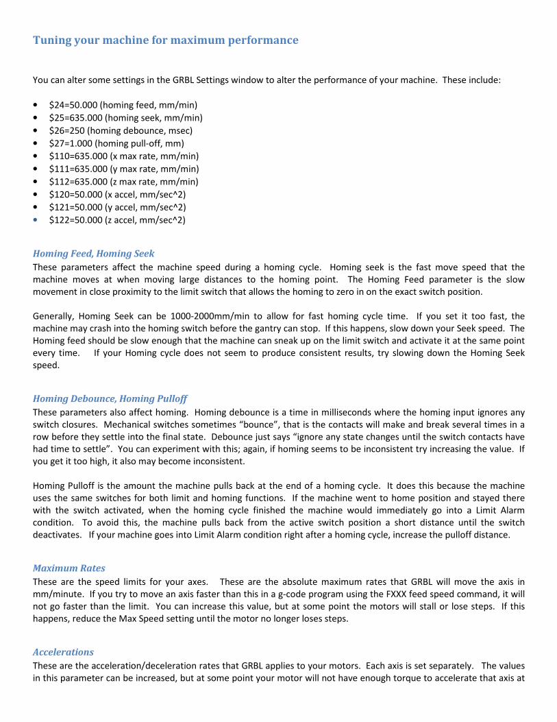
Tuning your machine for maximum performance
You can alter some settings in the GRBL Settings window to alter the performance of your machine. These include:
• $24=50.000 (homing feed, mm/min)
• $25=635.000 (homing seek, mm/min)
• $26=250 (homing debounce, msec)
• $27=1.000 (homing pull-off, mm)
• $110=635.000 (x max rate, mm/min)
• $111=635.000 (y max rate, mm/min)
• $112=635.000 (z max rate, mm/min)
• $120=50.000 (x accel, mm/sec^2)
• $121=50.000 (y accel, mm/sec^2)
• $122=50.000 (z accel, mm/sec^2)
Homing Feed, Homing Seek
These parameters affect the machine speed during a homing cycle. Homing seek is the fast move speed that the
machine moves at when moving large distances to the homing point. The Homing Feed parameter is the slow
movement in close proximity to the limit switch that allows the homing to zero in on the exact switch position.
Generally, Homing Seek can be 1000-2000mm/min to allow for fast homing cycle time. If you set it too fast, the
machine may crash into the homing switch before the gantry can stop. If this happens, slow down your Seek speed. The
Homing feed should be slow enough that the machine can sneak up on the limit switch and activate it at the same point
every time. If your Homing cycle does not seem to produce consistent results, try slowing down the Homing Seek
speed.
Homing Debounce, Homing Pulloff
These parameters also affect homing. Homing debounce is a time in milliseconds where the homing input ignores any
switch closures. Mechanical switches sometimes “bounce”, that is the contacts will make and break several times in a
row before they settle into the final state. Debounce just says “ignore any state changes until the switch contacts have
had time to settle”. You can experiment with this; again, if homing seems to be inconsistent try increasing the value. If
you get it too high, it also may become inconsistent.
Homing Pulloff is the amount the machine pulls back at the end of a homing cycle. It does this because the machine
uses the same switches for both limit and homing functions. If the machine went to home position and stayed there
with the switch activated, when the homing cycle finished the machine would immediately go into a Limit Alarm
condition. To avoid this, the machine pulls back from the active switch position a short distance until the switch
deactivates. If your machine goes into Limit Alarm condition right after a homing cycle, increase the pulloff distance.
Maximum Rates
These are the speed limits for your axes. These are the absolute maximum rates that GRBL will move the axis in
mm/minute. If you try to move an axis faster than this in a g-code program using the FXXX feed speed command, it will
not go faster than the limit. You can increase this value, but at some point the motors will stall or lose steps. If this
happens, reduce the Max Speed setting until the motor no longer loses steps.
Accelerations
These are the acceleration/deceleration rates that GRBL applies to your motors. Each axis is set separately. The values
in this parameter can be increased, but at some point your motor will not have enough torque to accelerate that axis at

the chosen rate. At this point, the motor will either stall, or start to lose steps. You can increase these values until the
motor stalls or loses steps, and then back the setting off by about 20% to give a safety margin.
The best way to determine if a motor is losing steps is to move the axis a large distance one direction, then the other.
You can write a small g-code program to do this, or use the G28 and G30 position buttons to move the axis back and
forth. Put a small pencil line on the axis v-slot at both ends of the travel, then repeatedly move the axis back and forth a
number of times. See if it still falls exactly on your pencil line at each travel extreme. If it shifts position over several
iterations, you may be losing steps.

G-Code Reference
Summary of GCODE Commands By Category
Set Up Commands
CODE COMMAND FORMAT PURPOSE
F Feed Speed Fn Designates feed rate, or rate
of movement, of the axes.
G4 Dwell Time G4/d Specifies a programmed delay
during a drill cycle.
G90 Absolute Coordinates G90 Indicates that absolute
motion will be used to
perform subsequent motion
commands.
G91 Incremental Coordinates G91 Indicates that incremental
motion will be used to
perform subsequent motion
commands.
G92 Set Absolute Position G92XxYyZz Sets new absolute
coordinates for the current
position.
M0 Program Pause M0 Pauses the .NC file run.
M30 End Of Data M30 Designates the end of a block
of commands in a file.
M3 Spindle On M3 or Starts the spindle.
M4 M4
M5 Spindle Off M5 Turns the spindle off.
M6 Tool Change M6T# Allows the tool to be changed
by turning off the spindle and
coolant and stopping the file.
M7 Coolant On M7 or Turns the coolant on.
M8 M8
M9 Coolant Off M9 Turns the coolant off.
M90 Output Off M90 OUT# Turns off the designated
output.
M91 Output On M91 OUT# Turns on the designated
output.
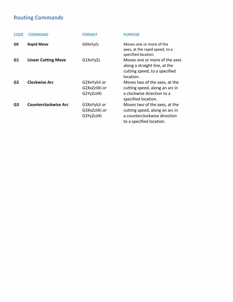
Routing Commands
CODE COMMAND FORMAT PURPOSE
G0 Rapid Move G0XxYyZz Moves one or more of the
axes, at the rapid speed, to a
specified location.
G1 Linear Cutting Move G1XxYyZz Moves one or more of the axes
along a straight line, at the
cutting speed, to a specified
location.
G2 Clockwise Arc G2XxYyIiJi or Moves two of the axes, at the
G2XxZzIiKi or cutting speed, along an arc in
G2YyZzJiKi a clockwise direction to a
specified location.
G3 Counterclockwise Arc G3XxYyIiJi or Moves two of the axes, at the
G3XxZzIiKi or cutting speed, along an arc in
G3YyZzJiKi a counterclockwise direction
to a specified location.

Drill Cycle Commands
CODE COMMAND FORMAT PURPOSE
G80 Drilling Cycle Off G80 Turns a drill cycle off.
G81 Standard Drilling Cycle G81XxYyZzRrPpFf Provides a feed-in, rapid-out
Without Dwell sequence used for standard
drilling without a dwell time.
G82 Standard Drilling Cycle G82XxYyZzRrPpFf Provides a feed-in, rapid-out
With Dwell sequence used for standard
drilling with a specified
dwell time.
G83 Peck Drilling Cycle G83XxYyZzRrQqVvPpFf Provides a series of feed-in,
peck drilling motions with full
retract used for drilling holes.
G87 Chip Break Drilling G87XxYyZzRrQqVvWwPpFf Provides a series of feed-in,
Cycle rapid-out motions that is similar to peck drilling, but
the retract is a specified distance
General Drill Cycle Command Format
G8n Xx Yy Zz Rr Qq Vv Ww Pp Ff
X the x coordinate of the hole
Y the y coordinate of the hole
Z the z coordinate of the hole
R the reference height for start of drill plunge
Q the initial z peck increment
V the subsequent z peck increment.
W the peck clearance, z retract between pecks
P the dwell time (seconds)
F the drilling federate, plunge speed
n an integer in the range of zero to nine

GRBL G-Code Restrictions
G-code Not supported by Grbl
Please note that unsupported G-code may cause Grbl to behave oddly, for example drifting into a corner. If
you purchase g-code derived from some other source, it may have g-codes that are not supported by GRBL.
G-
code Meaning Notes
G40 Tool radius comp off
This actually is the only mode which Grbl runs in (there's no way to turn on tool
radius compensation), so arguably this command should simply be ignored.[25]
Bug report on Github
Note this is now supported in Grbl v0.9i[26]
G41 Tool radius
compensation left [27]
G64 Constant velocity
mode [28]
G81 Canned drilling cycle Try setting the Drilling Method to Spiral instead of Canned Cycle[29]
G83 Deep hole drilling
canned cycle
A Perl program for post-processing a file which contains such commands is
available on github.[30]
G91.1 incremental distance
mode for arcs Note this is now supported in Grbl v0.9i[32]
G12 and 13 cut circular pockets to the specified radius and depth, using a helix or spiral motion.

Using the Work Coordinate Systems
If you have limit switches on your machine it opens up the world of work coordinate systems.
Note: These instructions are based on Grbl v0.8c and higher. Other control systems should support these
functions, but check the documentation. These are standard G codes but implementations may vary.
There are six user-definable work coordinate systems (WCS) available that are selected with the G54-G59
commands. These are modal; meaning that once you select a WCS all following commands will reference that
coordinate system until you select a different one. They are also persistent, meaning that they will be stored
between resets and power cycles.
You can also reference the absolute machine coordinate system (home position) using the G53 command, but
this command must be issued on every line that you want to reference machine zero on. (eg: G0 G53 X0 Y0
will send the tool to machine zero at rapid speed. The next command will reference the previously selected
WCS.)
What are work coordinate systems good for? The easiest way to think about it is that it allows you to set
multiple 'zero' locations on your machine which are stored in semi-permanent memory and can be recalled
after homing the machine.
For instance you could have a small vise that is semi-permanently mounted to the end of your work area and
the G55 WCS is set so the face of the non-moving jaw of the vice is X zero and a stop bolted to the table is Y
zero. This means that when you want to use the vise all you have to do is home the machine, select the G55
WCS, pickup Z zero and hit send on your G code file.
You can also have several different jigs that are fastened to the table and located by dowel pins. This allows
you to swap in a different jig, select the appropriate WCS and get right to work without having to indicate in
the zero location.
The first step to using work coordinate systems is to enable homing. On Grbl v0.8c that requires setting $16
and $17 to 1. In Grbl v0.9 the settings are $23 and $24.
You probably also want to set the step idle delay ($7) to 255 so the motors are locked all the time and the
machine will not drift or get bumped. In Grbl v0.9 this is the $15 setting.
After you run the homing cycle ($H) your machine absolute zero will be set. The standard location is in the
lower left corner, so that all the coordinates will be in positive space, although it doesn't really matter where
you zero the machine.
The next bit is important.
From now on you should only move the machine using the jog feature or by entering G code commands. If you
move the machine by hand it will not know where it is and you will lose your zero. You can't use a hand wheel
to set the Z depth either.
Once you have jogged the machine to your zero location, you can set a WCS by issuing the command: G10 P[1-
9] L20 X [offset] Y [offset] Z [offset]

Let me explain that a little bit.
The P[1-9] is used to select the work coordinate system to change. P1 = G54, P2 = G55, etc.
The X, Y and Z are all optional (but you need at least one otherwise there is nothing to set.)
The [offset] is optional (in that it can be '0') but is useful to compensate for the radius of the tool you are
picking up your zero with.
For example, my procedure when setting a WCS is as follows:
1. Chuck up a piece of 1/4" drill rod. I have pre-measured this rod and it is .250" in diameter +/- .0005".
2. Home the machine.
3. Jog over past the edge of the work piece or jig that I want to indicate as 'zero' in the X axis.
4. Lower the Z and jog back to the edge. I sneak up on it until a piece of paper just gets captured between
the rod and the edge.
5. Set the X zero for the selected WCS. The value to enter is 1/2 the diameter of the rod + the thickness of
the paper (I usually use .004"). So I would enter 'G10 P1 L20 X-0.129' The value you enter is the
distance from zero to where the center of the tool actually is. It can be positive or negative.
6. Repeat the procedure for the Y axis.
I do it a little differently for the Z axis. You will have to pick up the Z zero every time you change tools (unless
you built a tool changer.) The procedure I use for the Z axis is as follows:
1. Chuck up the first tool I'm going to use.
2. Move over to a flat area on the work piece that is designated Z zero (although it doesn't have to be Z
zero, you can input any offset you like to compensate for material thickness.)
3. Using the same 1/4" diameter drill rod, jog the Z down until the rod no longer passes under the tool.
4. Set Z zero in the work coordinates: 'G10 P1 L20 Z0.25'
Note that there are nine settings for the work coordinate systems (P1-9) but only 6 WCS selection commands
in the G54-G59 range. How do you select the other three? The last three work coordinate systems are
accessed using G59.1, G59.2 and G59.3. This is not currently supported in Grbl and is unlikely to be added. So
in Grbl there are only six usable WCS.
What about G92?
G92 changes the current coordinate system to the current tool position (plus any offset you enter.) This offset
remains in effect until you use G92 to change it again, or use G92.1 to remove all offsets.
G92 is useful to set a quick zero position for running parts, but I don't use it as a general rule. The main reason
is that G92 is not persistent across resets and power cycles so if you have to E-Stop, or your run is interrupted
for some reason, you have to re-pickup your zero.
What about G28 and G30?
G28 and G30 are not WCS settings.

G28 and G30 are persistent, stored positions that you can send the machine to with a single command. G28.1
and G30.1 are used to store the current machine position in absolute machine coordinates.
You set the G28 position by moving the machine to the position you wish to set and issuing G28.1. G30 is set
the same way, but with G30.1. These commands do not take any values, and in v0.9 and possibly v0.8c of Grbl,
passing a value will cause the machine to move.
Once they are set, you can issue the G28 or G30 command and the machine will move all three axis, at rapid
speed, to the predefined position.
Note: These commands will not raise the Z axis before moving the X and Y so use caution.
You can specify an optional, intermediate position by adding X, Y or Z values to the command.
Important Note: These coordinates are in the current WCS, not absolute machine values.
So if you wanted to raise the Z first, you could say G28 Z1.5 and it would rapid the Z to 1.5 - in the current WCS
- and then rapid move X, Y and Z to the saved position.
Overview
http://www.shapeoko.com/forum/viewtopic.php?f=3&t=5576&p=41406
Simplest workflow is this:
• First time:
o Home the machine.
o Jog to where you want your WCS 0, 0, 0 to be.
o Input G10 L20 P1 X0 Y0 Z0 or press disconnect/reconnect.
o GRBL calculates the offsets from machine origin and stores them in non-volatile memory
(EEPROM).
• Every other time:
o Home the machine. Done.
• Alternate:
o Home the machine
o Set G28 to 0,0,(Z height)
o Use G28 to return to home position, instead of Homing again
o This is preserved through a power down
References
• http://wiki.linuxcnc.org/cgi-bin/wiki.pl?CoordinateSystems


