catalogo carrier de la familia 30 HKS enfriadora de agua
48
30HKS 20 A 60 TR RENFRIADORES DE LÍQUIDOS CON CONDENSACIÓN A AGUA Y COMPRESORES SCROLL WATER-COOLED CHILLERS WITH SCROLL COMPRESSOR 50/60Hz DATOS TÉCNICOS DEL PRODUCTO PRODUCT TECHNICAL DATA
Transcript
30HKS 20 A 60 TR
RENFRIADORES DE LÍQUIDOS CON CONDENSACIÓN AAGUA Y COMPRESORES SCROLL
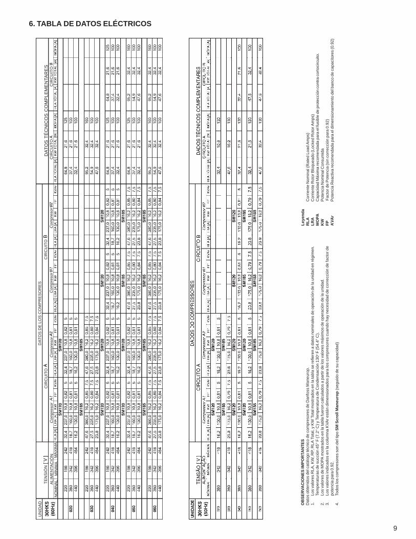
6. TABLA DE DATOS ELÉCTRICOS................................................................................................................................... 9
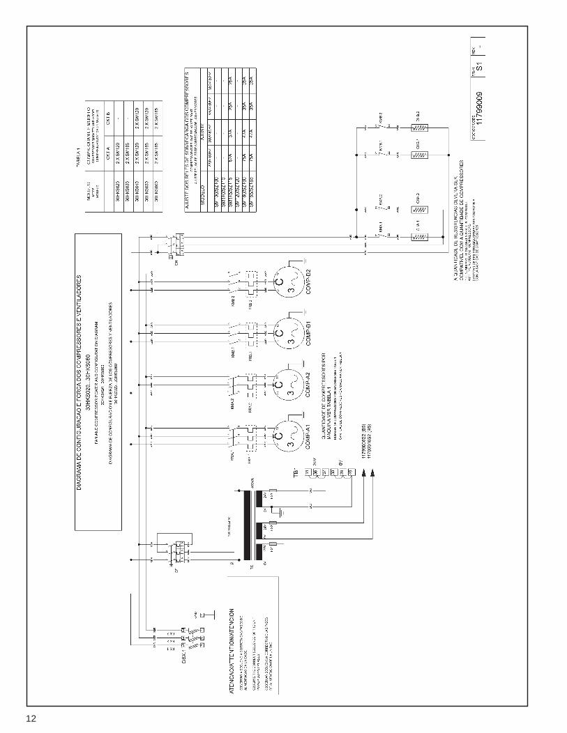
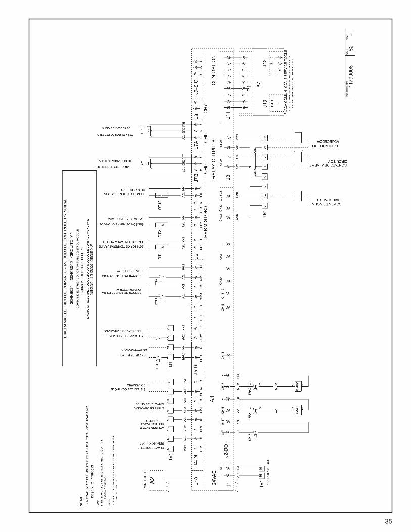
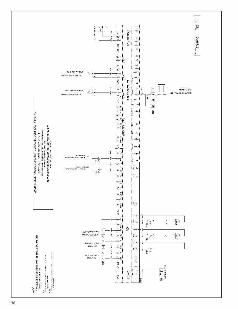
7. DIAGRAMAS ELÉCTRICOS / DISPOSICIÓN DE LOS COMPONENTES ELÉCTRICOS ........................................... 10
9. PROCEDIMIENTO PARA SELECCIÓN ........................................................................................................................ 17
10. DATOS DE DESEMPEÑO ........................................................................................................................................... 18
11. TABLAS DE PÉRDIDA DE CARGA (INTERCAMBIADORES DE CALOR) ................................................................ 19
12. PÉRDIDAS DE CARGA EN LOS CONDENSADORES .............................................................................................. 20
13. NOTAS PARA DATOS ELÉCTRICOS ......................................................................................................................... 20
14. GUÍA PARA ESPECIFICACIONES – 30HKS, 020 A 060 ........................................................................................... 21
15. TABLA DE CONVERSIÓN DE UNIDADES ................................................................................................................. 24
4
2. 2. Mantenimiento Sencillo
• Fácil acceso a la caja eléctrica y a todos suscomponentes.
• Presión de succión y de descarga de lectura fácil, asícomo informaciones de temperatura exhibidas en undisplay específico.
2. 3. Subenfriador de Líquido
Nuestros equipos usan la técnica del subenfriamiento paramejorar la eficiencia buscando obtener mayor efecto derefrigeración por KW consumido. El agua más fría queviene de la torre de enfriamiento entra en la parte másbaja de los tubos de los condensadores (ver dibujo aseguir).
1. INTRODUCCIÓN
Carrier presenta su nueva línea de enfriadores de líquido,proyectados para satisfacer las necesidades de hoy ymañana.
• Control Electrónico de alta precisión y eficiencia• Refrigerante R-22• Menor costo de transporte e instalación• Compresores Scroll• Válvula de expansión termostática• Mayor variedad de tamaños• Versatilidad de aplicación
Todas la unidades están equipadas con control PRO-DIALOGPLUS NRCP para optimizar la eficiencia del circuitorefrigerante. A todas las unidades se las prueba y se lascarga con refrigerante HCFC22 de fábrica.
2. CARACTERÍSTICAS
• El proyecto y la construcción de alta calidad hacen del30 HKS la mejor elección.
• Las unidades 30HKS están equipadas con compresoresdel tipo SCROLL proyectados para trabajar muysilenciosamente y en bajos niveles de vibración.
• Las unidades 30HKS exceden los niveles comunes deeficiencia para los patrones de la industria, tanto parala operación a plena carga como a carga parcial,economizando los costos operacionales y disminuyendolos costos con electricidad.
• El control del 30HKS es completamente automático. Latemperatura del agua de salida está continuamentecontrolada para detectar cambios en la carga y en elflujo. Esta combinación proporciona el más preciososcontrol de temperatura disponible.
• Dos circuitos de refrigerante independientes – elsegundo asume automáticamente cuando el primeropresenta problemas, manteniendo el acondicionamientoen carga parcial.
• Instalación fácil – los Chillers 30HKS está suministradoscon carga total de refrigerante y con conexiones defuerza y agua convenientemente localizadas.
• Autodiagnóstico – exhibición rápida del estado actualde la máquina.
• Conceptos de compresores múltiples aumenta laeficiencia en carga parcial y minimiza la corriente dearranque.
• Arranque directo.
2. 1. Instalación Fácil
Las unidades 30GS tienen un proyecto compacto que ocupaespacio mínimo en recintos abiertos y se las suministra conun paquete completo para instalación. No hay controlesextras, temporizadores, auxiliares de arranque u otros ítemsque serán instalados. Las conexiones hidráulicas sonsencillas debido a la utilización de flanges en el evaporador.
Salida del agua delcondensador
Refrigerante en elestado líquido inunda elconjunto subenfriador.
Dirección de flujo agua
Cabezal de entrada
Entrada en elsubenfriador
C o n j u n t osubenfriador
Refrigerantecondensado
Condensador
Encuen t ratres pasos
Cabezalde salida
5
2. 8. Control PRO-DIALOGPLUS NRCP
El PRO-DIALOGPLUS NRCP es un sistema avanzado decontrol numérico que combina inteligencia y gran simplicidadoperacional.
El PRO-DIALOGPLUS NRCP garantiza un control inteligentede la temperatura del agua de salida disminuyendo elconsumo de energía.
• El PID es un algoritmo de control de compensaciónpermanente controlando la diferencia entre latemperatura de entrada y salida de cambiador de calor,y que anticipa las variaciones de carga, garantizandola estabilidad de la temperatura del agua de salida ypreviniendo ciclos innecesarios del compresor.
• Varias posibilidades de capacidad en relación a la cargaaseguran un mejor arranque a la baja temperaturaexterior, y permite el uso de uno de los circuitos derefrigerante como parte de un sistema de reserva.
• Reset del punto de ajuste de la temperatura del aguade salida, basado en la temperatura del aire externo.
El nuevo control permite al usuario hacer una programaciónde los períodos activos e inactivos de la unidad. A travésde él se pueden programar el día, mes, año y hora en quela unidad se encenderá o se apagará.
2. 4. Fácil Mantenimiento de los compresores
El equipo está proyectado para facilitar servicios demantenimiento o inspección de los compresores. Bastaretirar los tornillos de los pies y desbrasar la descarga ysucción para la retirada del compresor.
2. 5. Filtros Secadores
Los circuitos de refrigerante se los mantienen libres dehumedad que puede perjudicar el funcionamiento en elsistema.
2. 6. Calentadores de Cárter
Auxilia cada compresor, mientras esté parados, a separarel refrigerante del aceite y garantizar buena lubrificación ennuevo arranque.
2. 7. Display
Uno en cada circuito de refrigeración, indica el tenor dehumedad en el sistema y es posible determinar la hora decambiar los filtros.
6
Para más detalles sobre el PRO-DIALOGPLUS NRCP, utilice el manual de Controles y Soluciones de Defectos, código117.94.016.
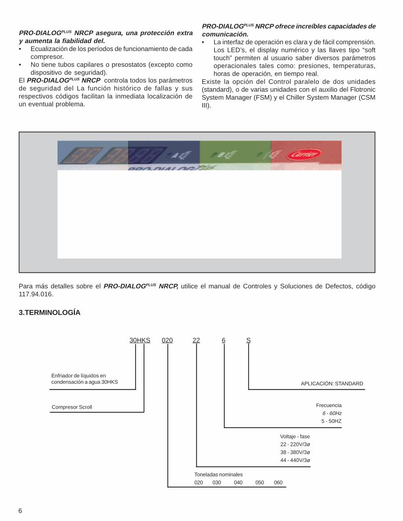
PRO-DIALOGPLUS NRCP ofrece increíbles capacidades decomunicación.• La interfaz de operación es clara y de fácil comprensión.
Los LED’s, el display numérico y las llaves tipo “softtouch” permiten al usuario saber diversos parámetrosoperacionales tales como: presiones, temperaturas,horas de operación, en tiempo real.
Existe la opción del Control paralelo de dos unidades(standard), o de varias unidades con el auxilio del FlotronicSystem Manager (FSM) y el Chiller System Manager (CSMIII).
PRO-DIALOGPLUS NRCP asegura, una protección extray aumenta la fiabilidad del.• Ecualización de los períodos de funcionamiento de cada
compresor.• No tiene tubos capilares o presostatos (excepto como
dispositivo de seguridad).El PRO-DIALOGPLUS NRCP controla todos los parámetrosde seguridad del La función histórico de fallas y susrespectivos códigos facilitan la inmediata localización deun eventual problema.
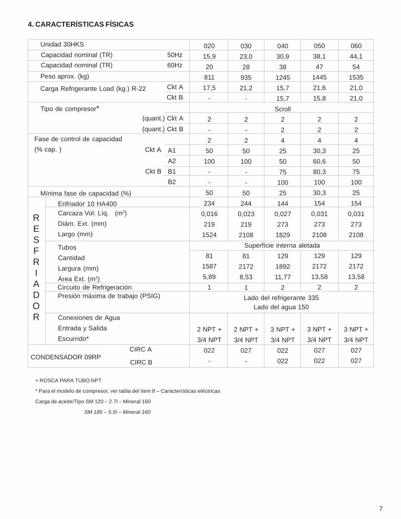
3.TERMINOLOGÍA
30HKS 020 22 6 S
APLICACIÓN: STANDARD
Frecuencia
6 - 60Hz
5 - 50HZ
Voltaje - fase
22 - 220V/3ø
38 - 380V/3ø
44 - 440V/3ø
Toneladas nominales
020 030 040 050 060
Enfriador de líquidos encondensación a agua 30HKS
Compresor Scroll
7
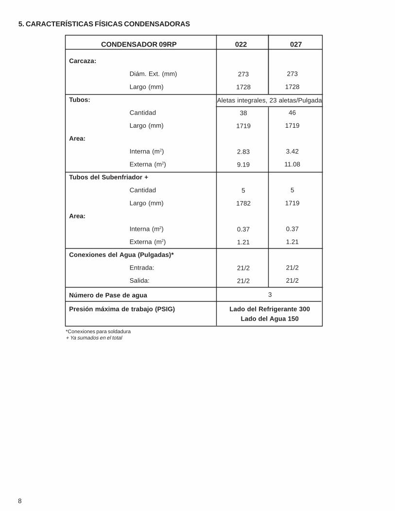
4. CARACTERÍSTICAS FÍSICAS
+ ROSCA PARA TUBO NPT
* Para el modelo de compresor, ver tabla del ítem 8 – Características eléctricas
Carga de aceite/Tipo SM 120 – 2.7l – Mineral 160
SM 185 – 5.5l – Mineral 160
020
15,9
20
811
17,5
-
2
-
2
50
100
-
-
50
234
0,016
219
1524
81
1587
5,89
1
2 NPT +
3/4 NPT
022
-
030
23,0
28
935
21,2
-
2
-
2
50
100
-
-
50
244
0,023
219
2108
81
2172
8,53
1
2 NPT +
3/4 NPT
027
-
040
30,9
38
1245
15,7
15,7
Scroll
2
2
4
25
50
75
100
25
144
0,027
273
1829
129
1892
11,77
2
3 NPT +
3/4 NPT
022
022
050
38,1
47
1445
21,6
15,8
2
2
4
30,3
60,6
80,3
100
30,3
154
0,031
273
2108
129
2172
13,58
2
3 NPT +
3/4 NPT
027
022
060
44,1
54
1535
21,0
21,0
2
2
4
25
50
75
100
25
154
0,031
273
2108
129
2172
13,58
2
3 NPT +
3/4 NPT
027
027
Fase de control de capacidad
(% cap. )
Ckt A
Ckt B
(quant.) Ckt A
(quant.) Ckt B
Ckt A
Ckt B
A1
A2
B1
B2
Unidad 30HKS
Capacidad nominal (TR) 60Hz
Peso aprox. (kg)
Carga Refrigerante Load (kg.) R-22
Tipo de compresor*
Mínima fase de capacidad (%)
RESFRIADOR
Enfriador 10 HA400Carcaza Vol. Líq. (m3)
Diám. Ext. (mm)
Largo (mm)
Circuito de Refrigeración
Tubos
Cantidad
Largura (mm)
Área Ext. (m2)
Presión máxima de trabajo (PSIG)
Conexiones de Agua
Entrada y Salida
Escurrido*
Superfície interna aletada
Lado del refrigerante 335Lado del agua 150
CONDENSADOR 09RPCIRC A
CIRC B
Capacidad nominal (TR) 50Hz
8
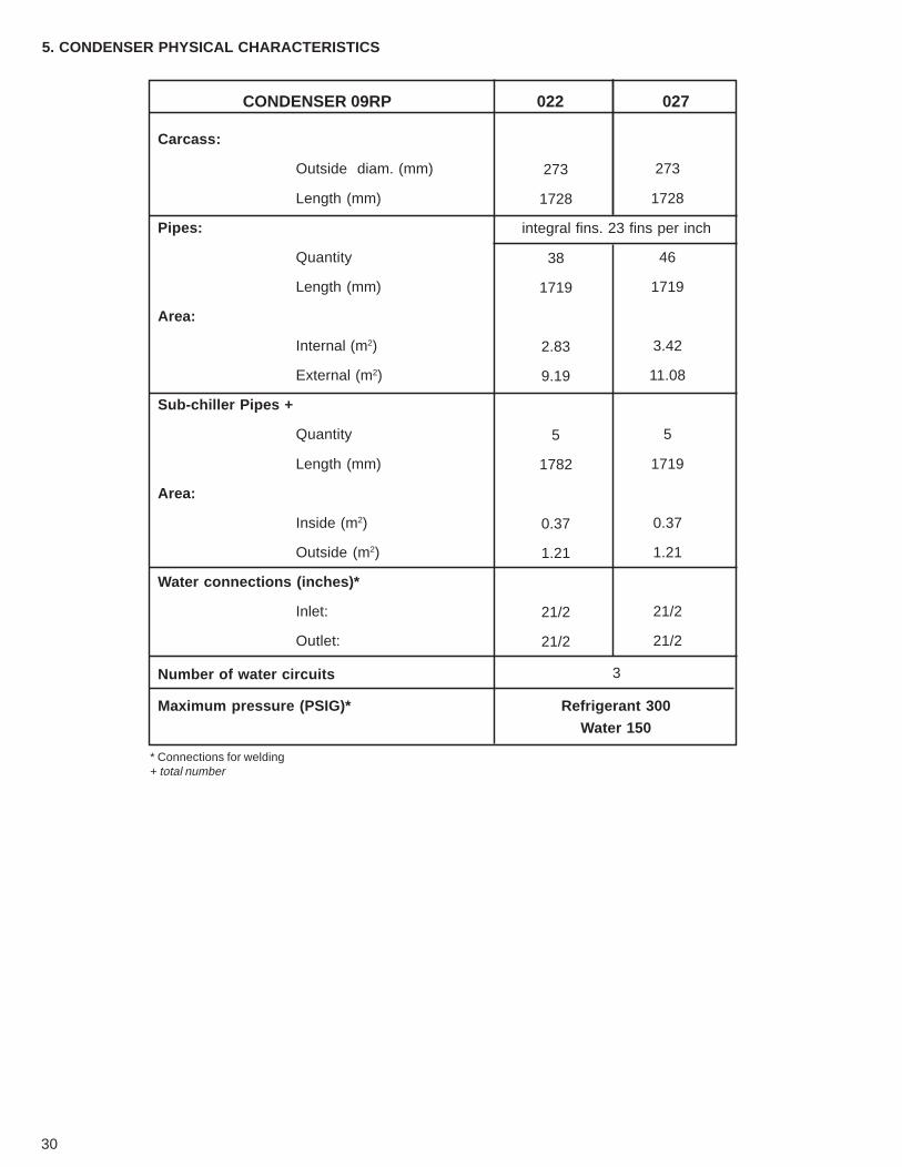
CONDENSADOR 09RP
Carcaza:
Diám. Ext. (mm)
Largo (mm)
Tubos:
Cantidad
Largo (mm)
Area:
Interna (m2)
Externa (m2)
Tubos del Subenfriador +
Cantidad
Largo (mm)
Area:
Interna (m2)
Externa (m2)
Conexiones del Agua (Pulgadas)*
Entrada:
Salida:
Número de Pase de agua
Presión máxima de trabajo (PSIG)
022
Aletas integrales, 23 aletas/Pulgada
273
1728
38
1719
2.83
9.19
5
1782
0.37
1.21
21/2
21/2
Lado del Refrigerante 300
Lado del Agua 150
273
1728
46
1719
3.42
11.08
5
1719
0.37
1.21
21/2
21/2
027
3
*Conexiones para soldadura+ Ya sumados en el total
Determine el modelo de la unidad y las condiciones deoperación necesarias para atender las siguientescondiciones de proyecto:
Carga Térmica .................................. 25TR (75600 Kcal/h)Temperatura de agua fría en la salida del Cooler (T1) .... 7,0o CAumento de temperatura en el agua fría ................. 5,5o CTemperatura del aguan en la entrada del condensador (T2) . 30o CCaudal de agua fría .................................................. 3,8 l/sCaudal de agua de condensación ............................ 4,2 l/s
Entre en la tabla de la unidad 30HKS 030 con la temperatu-ra de 7.0o C (para la salida del agua del Cooler, 30o C parala temperatura de la entrada de agua en el condensador.
Si T1 y T2 no están presentadas en las tablas, proceda dela siguiente forma:
• Si la temperatura de agua fría en la salida del chillerestá entre 7 y 6o C (6.3o C, por ejemplo), interpolar losdatos de la tabla entre la columna que presentasupercalentamiento 4oC / T1 = 7oC / T2 = 30o C, y lacolumna que presenta supercalentamiento 4o C / T1 =6o C / T2 = 30o C.
• Si la temperatura del agua en la entrada delcondensador fuera de 33o C, por ejemplo, interpolarlos datos de la tabla entre la columna que presentasupercalentamiento 4oC / T1 = 7oC / T2 = 30oC, y lacolumna que presente supercalentamiento 4o C / T1 =7o C / T2 = 35o C.
Para las condiciones arriba presentadas, la unidadseleccionadora es la 30HKS trabajando en las siguientescondiciones:Temperatura del agua fría en la salida del cooler (T1) .. 7,0o CTemperatura del agua en la entrada del condensador (T2) . 30o CConsumo ............................................................ 25,669 WCapacidad de enfriamiento .............................. 28,24 TRsCaudal del agua fría ...............................................4,27 l/sCaudal del agua de condensación .......................... 5,32l/s
Las tablas de desempeño presentadas en las siguientespáginas, son válidas para los modelos 30HKS en lascondiciones a seguir:a) STD (Temperatura de Descarga Saturada) ... ≤ 48,9o Cb) Fac to r de inc rus tac ión para en f r iador ycondensador .............................. 0.0001 m2 oC H / Kcalc) Subenfriamiento .................................................. 5,5o Cd) Diferencial entre temperatura de condensaciónsaturada .................................................................. 5,5o Ce)Diferencial entre temperatura de condensaciónsaturada (TSD) y temperatura del agua en la entrada delcondensador (T2) ................................................. 11,3o C
NOTA: Cuando se seleccione una unidad 30HKS encondiciones diferentes ∆T = 11,3o C para el ítem y utilice lacurva para corregir los valores de la tabla de capacidad.
CAPAC.
EER
∆T
Corrección = Valor de la Tabla de Capacidad (x) % deCorrección de la Capacidad (según la curva de arriba).
Para un ∆T diferente de 11,3o C, corregir la capacidad y elEER de acuerdo con los porcentuales (positivos y negati-vos) de la tabla de arriba.
Se recomienda que las unidades no sobrepasen límites desubenfriamiento:Mínimo: 2,8o CMáximo 8,3o C
% C
OR
RE
CC
IÓN
18
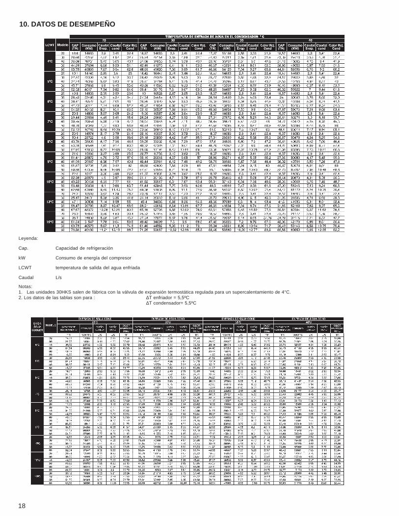
10. DATOS DE DESEMPEÑO
Notas:1. Las unidades 30HKS salen de fábrica con la válvula de expansión termostática regulada para un supercalentamiento de 4°C.2. Los datos de las tablas son para : ∆T enfriador = 5,5ºC
∆T condensador= 5,5ºC
Leyenda:
Cap. Capacidad de refrigeración
kW Consumo de energía del compresor
LCWT temperatura de salida del agua enfriada
Caudal L/s
19
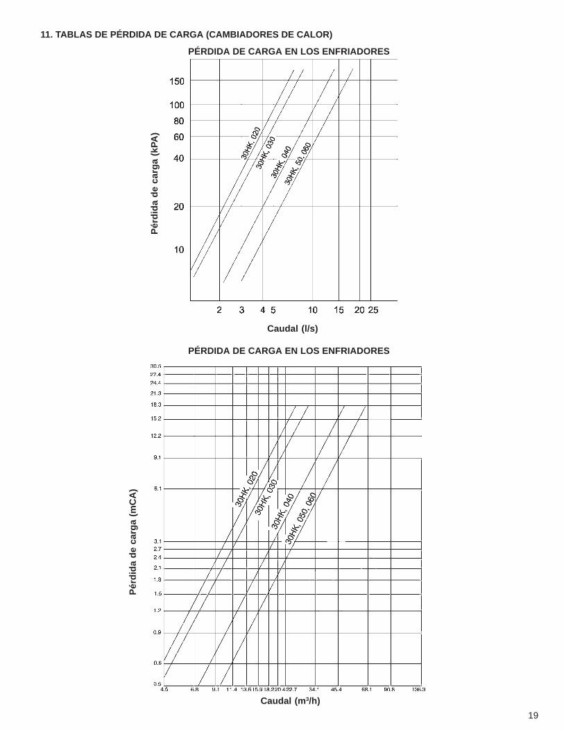
11. TABLAS DE PÉRDIDA DE CARGA (CAMBIADORES DE CALOR)
PÉRDIDA DE CARGA EN LOS ENFRIADORES
PÉRDIDA DE CARGA EN LOS ENFRIADORES
Caudal (l/s)
Pér
did
a d
e ca
rga
(mC
A)
Caudal (m3/h)
Pér
did
a d
e ca
rga
(kPA
)
20
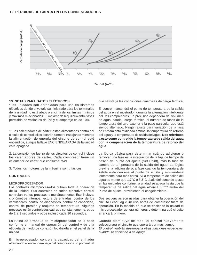
12. PÉRDIDAS DE CARGA EN LOS CONDENSADORES
Pér
dida
de
carg
a (m
CA
)
Caudal (m3/h)
13. NOTAS PARA DATOS ELÉCTRICOS*Las unidades son apropiadas para uso en sistemaseléctricos donde el voltaje suministrado para los terminalesde la unidad no está abajo o encima de los límites mínimosy máximos relacionados. El máximo desequilibrio entre fasespermitido de voltios es de 2% y el amperaje es de 10%.
1. Los calentadores de cárter, están alimentados dentro delcircuito de control, ellos estarán siempre trabajando mientrasla alimentación de energía del circuito de control estéencendida, aunque la llave ENCIENDE/APAGA de la unidadesté apagada.
2. La conexión de fuerza de los circuitos de control incluyelos calentadores de cárter. Cada compresor tiene uncalentador de cárter que consume 75W.
3. Todos los motores de la máquina son trifásicos
CONTROLES
MICROPROCESADORLos controles microprocesados cubren toda la operaciónde la unidad. Sus controles de rutina ejecutiva centralcontrolan varios procesos simultáneamente. Eso incluye:cronómetros internos, lectura de entradas, control de losventiladores, control de diagnóstico, control de capacidad,control de presión y reajuste de temperatura. Algunosprocesos están controlados casi que constantemente, otrosde 2 a 3 segundos y otros incluso cada 30 segundos.
La rutina de arranque del microprocesador se la haceconforme el manual de operación del control y de unaetiqueta de modo de conexión localizada en el panel de launidad.
El microprocesador controla la capacidad del enfriadoralternando el enciende/apaga del compresor a un porcentual
que satisfaga las condiciones dinámicas de carga térmica.
El control mantendrá el punto de temperatura de la salidadel agua en el mostrador, durante la alternación inteligentedel los compresores. La precisión dependerá del volumende agua, caudal, carga térmica, el número de fases de latemperatura del aire exterior y la pase particular que estásiendo alternado. Ningún ajuste para variación de la tasade enfriamiento midiendo ambos; la temperatura de retornodel agua y la temperatura de salida del agua. Nos referimosa esto como control de la temperatura de salida del aguacon la compensación de la temperatura de retorno delagua.
La lógica básica para determinar cuándo adicionar oremover una fase es la integración de la faja de tiempo dedesvío del punto del ajuste (Set Point), más la tasa decambio de temperatura de la salida del agua. La lógicaprevine la adición de otra fase cuando la temperatura desalida está cercana al punto de ajuste y moviéndoselentamente para más cerca. Si la temperatura de salida delagua es menor que 1.7°C o 3.3°C abajo del punto de ajusteen las unidades con brine, la unidad se apaga hasta que latemperatura de salida del agua alcance 3.3°C arriba delPunto de ajuste, previniendo el congelamiento.
Dos secuencias son usadas para obtener la operación delcircuito Lead/Lag e incluso horas de compresor fuera deoperación. En la medida en que se enciende la unidad elmicroprocesador genera números y determina qué circuitoarrancará primero.
Cuando disminuye de fase, el control nuevamenteseleccionará el circuito que operará por más tiempo.El control también desempeña otras funciones especialescuando se enciende o se apaga.
21
TERMISTORES/TRANSDUCTORES
Dos termistores se utilizan para suministrar las temperaturaspara el microprocesador. Un tercer termistor, (RT10) puedeusarse como sensor de temperatura remota con el objetivode hacer la lectura del aire externo.
Cuatro transductores son usados para suministrar laspresiones del sistema. (Ver Manual de Operación, Controly Solución de Defectos).
T1 = Temperatura de salida del agua enfriada delevaporador.
T2 = Temperatura de entrada (retorno) del agua para elevaporador.
T10 = Sensor de temperatura del aire externo (OAT).
SECUENCIA DE CONTROL
Ciclo de apagado – durante el ciclo de apagado de la unidadse energizan las resistencias del cárter.
Arranque – después de que se enciende la unidad ocurreun procedimiento de prearranque durante 2 min. Eso ocurrepara que el microprocesador haga una autoverificación yaguarde para que la temperatura se estabilice. El primercircuito a dar arranque puede ser el A o B (Lead/Lagautomático). El control de la rampa de carga limita la cargadel compresor en el arranque, y uso innecesario delcompresor. El microprocesador limita el suplemento y latemperatura del agua cae (solamente en el arranque) para0.6°C/ por minuto.
CONTROL DE CAPACIDAD
En la primera llamada para enfriamiento el microprocesadorda el arranque en el compresor inicial en la 1ª fase delventilador en el circuito principal. Los calentadores del cárterse desenergizan cuando el compresor inicia. Si másenfriamiento es necesario, más compresores sonconectados alternándose los circuitos en Lead/Lag. Lavelocidad en la cual la capacidad se aumenta o disminuyees controlada por el desvío de temperatura del punto deajuste y la tasa de cambio de temperatura del agua enfriada.
A medida en que se exige menos enfriamiento, los circuitosse apagan (o se descargan) en un orden que procuraequilibrar el tiempo de operación de cada circuito.
CONDICIONES DE ALARMA(LED’S SEÑALADORES)
Todos los dispositivos de seguridad en el enfriador operana través del panel de protección del compresor. El presostatode alta presión apaga directamente el compresor a travésdel panel de protección del compresor. Para otrosdispositivos de seguridad el microprocesador:
( 1) Toma la decisión correcta al encender un compresorpor falla de seguridad o mala lectura del sensor (2) señalala alarma en el display y (3) suministra el código de falla enel mostrador
El enfriador permanece en el modo de seguridad hasta elrearme sólo entonces vuelve al control normal.
DISPOSITIVO DE SEGURIDAD POR PÉRDIDA DE CARGADE REFRIGERANTE
El dispositivo se acciona si la presión del sistema cae abajodel mínimo.
CORTE POR ALTA PRESIÓN
El presostato apaga el compresor si la presión de descargadel compresor aumenta hasta 2937 kPa.
ANTIRRECICLAJE DEL COMPRESOR
Esta función limita la alternancia del compreso.
PROTECCIÓN CONTRA LA FALTA DE CAUDAL
Esta protección se la suministra por la diferencia entre latemperatura de entrada y la salida del agua del evaporadorleída por los sensores. Actuará caso la variación de latemperatura sea menor que 1.8°C.
FALLAS EN EL SENSOR
Las fallas son detectadas por el microprocesador.
DIAGNÓSTICO
El microprocesador puede ser colocado para prueba rápida(vea el manual de controles y soluciones de defectos), sinequipos o herramientas adicionales.
14.GUÍA PARA ESPECIFICACIONES 30HKS, 020-060
Grupos enfriadores de líquidos con compresores Scrolly condensadores a aire.Variación de tamaño: 20 a 30 toneladasNúmero del modelo Carrier 30 HKS
PARTE 1 – CONSIDERACIONES GENERALES
1.01 – DESCRIPCIÓN DEL SISTEMAA - Enfriadores de líquido con condensación a agua con-
trolado por microprocesador utilizando compresoresScroll y válvulas de expansión termostática.
1.02 –CALIDAD ASEGURADAA - La unidad debe ser seleccionada de acuerdo con el
patrón ARI 590-92.B - La máquina debe estar proyectada de acuerdo con
la ASHRA-E 15, última revisión, y ASME donde seaapropiado.
C - La unidad debe ser totalmente verificada dentro de
22
la fábrica.
1.03. - ENTRADA, STOCK Y MANOSEOA - La unidad debe ser guardada y manoseada conforme
recomendaciones del fabricante.B - Los controles de la unidad deben ser capaces de
resistir a una temperatura de hasta 85°C en elcompartimento de control por un tiempo indefinido.
PARTE 2 - PRODUCTOS
2.01 - EquipoA - General
Enfriador de líquido con condensación a aire, piezaúnica, armado en fábrica. Juntamente con el gabinetede la unidad deben estar todo el cableado, tubería,controles, carga refrigerante R-22 y las opcionesespeciales de fábrica requeridas previamente alarranque de campo.
B - Gabinete de la Unidad1 - La estructura debe ser de perfiles de acero galvani-
zado.2 - Preparación de la superficie, a la superficie se la
debe chorrear con abrasivo y grado mínimo SA 2.5.La limpieza después del chorro debe hacerse con elaire seco exento de aceite.
3 - Pintura, aplicación de shop-primer como máximohasta 4h después del chorro. El espesor de la cama-da de pintura debe ser de 30 micrómetros.
C - Compresores1 - Solamente del tipo Scroll.2 - Armados sobre calces de goma para amortiguación
de las vibraciones.
D - Evaporador1 - Tipo casco y tubos con tapa removible2 - Los tubos deben ser internamente aumentados sin
costuras de cobre y expandidos contra el espejo.3 - Equipado con conexiones de agua del tipo flange.4 - El casco debe ser aislado con una espuma de ¾ de
PVC (19mm) de factor K máximo de 0,040 W/m.K.5 - El proyecto debe incorporar 2 circuitos refrigerantes
de expansión directa independientes.6 - Al evaporador se le debe probar y sellar de acuerdo
con el código ASME para tener una presión del ladorefrigerante de funcionamiento de 1916 kPa y unapresión mínima del lado del agua de 2068 kPa.
E - Condensador1 - El serpentín es de condensación a aire con el
subenfriador integral, construida de aletas dealuminio mecánicamente conectadas a los tubos decobre sin enmiendas los cuales se limpian,deshidratados y sellados.
2 - Los serpentines de condensación a aire debesometerse a pruebas de fuga de 1034 kPa, y unaprueba de presión de 3013 kPa.
F - Componentes de Refrigeración
Los componentes del circuito del refrigerante deben in-cluir dispositivos de protección del lado de alta presión,válvulas de servicio de líneas de líquido, filtro secadorcon núcleos recambiables, display de humedad, válvu-la de expansión termostática (TXV), y carga completade refrigerante para operación.
G – Controles, seguridad y diagnósticos1 – Controles
a) Las unidades deben incluir los componentes mínimossiguientes:1 - Microprocesador2. - Bloques terminales de los circuitos de control y
alimentación.3. - Panel sinóptico4. - Termistores, y/o transductores de presión
b) Capaz de realizar las siguientes funciones:1. - Lead / Lag de circuito automático.2. - Control de capacidad basado en la temperatura de
salida del agua enfriada y compensada por la tasade cambio de temperatura de retorno del agua.
3. - Limitación de la tasa de rampa de carga de tempe-ratura del agua enfriada en el arranque a 0.56o C/min., para prevenir el bloqueo por demanda excesivade carga en el arranque.
4. - Tabla de programación horaria.5. - Rearme de temperatura de salida del agua enfriada,
basado en el agua de retorno.6. - Control de límite de demanda con control de 2 puntos
(0 a 100% cada uno).
2 – Seguridada. La unidad debe estar equipada con termistores y
todos los componentes necesarios en conjugacióncon el sistema de control para suplir la unidad conlas siguientes protecciones:
1 - Protección contra la pérdida de la carga de refrige-rante.
2 - Detectar el bajo flujo del agua.3 - Protección contra la baja temperatura del agua
enfriada (anticongelamiento).4 - Protección contra alto o bajo supercelentamiento.5 - Protección contra el bajo voltaje de entrada en los
controles.6 - Señal visual de alarma (luz de la alarma).7 - Presostato de alta presión.
b. Los compresores y motores deben ser equipados conlos siguientes tipos de protección:1 - Sobrecarga de presión.2 - Sobrecarga eléctrica por el uso de contactores
termomagnéticos. Los disyuntores deben abrir to-das las 3 fases caso haya sobrecarga en cualquierfase (condición de la fase única)
3 – Diagnóstico
a. El módulo del mostrador diagnóstico debe ser capazde indicar la condición de aislamiento de seguridad
23
mostrando un código el cual se explicará en el mostrador.Las informaciones a ser analizadas son:
1 - Trabado del compresor.2 - Pérdida de carga de refrigerante.3 - Bajo caudal de agua.4 - Protección contra congelamiento en el evaporador.5 - Alto o bajo supercalentamiento en la succión.6 - Mal funcionamiento del transductor o termistor.7 - Temperatura de salida y entrada del agua.8 - Presión del compresor y evaporador.9 - Todos los puntos de ajuste.10 - Hora.
b. El módulo en asociación con microprocesador debetambién ser capaz de mostrar los resultados de unaprueba de funcionamiento para verificar la operaciónde cada llave, termistor, ventilador y compresor antesde ser dado el arranque en el enfriador.
c. Suministrar los resultados para una fuente externa.
H – Características operacionales1 - La unidad debe ser capaz de arrancar con una tem-
peratura de entrada del agua de 35/C en elevaporador.
2 - El control de capacidad del refrigerante debeefectuarse a través del uso del compresor.
3 - Dos circuitos refrigerantes deben proteger contra lapérdida total de capacidad.
4 - La Unidad debe tener la opción Lead / Lag automáti-co para automáticamente alterar el circuito principalpara asegurar el uso equilibrado de todos loscompresores.
I – Motores1 - Los motores del compresor deben ser enfriados por
el pasaje de gas de succión alrededor de las bobi-nas del motor.
2 - Motores del ventilador del condensador deben serde tres fases con cojinetes permanentemente lubri-ficados y aislamiento clase B.
J – Exigencias Eléctricas1 - El suministro de fuerza eléctrica primaria de la unidad
(3 fases) debe ser conectado a un único local, con-forme diagramas eléctricos.
2 - La unidad debe ser embarcada con control y cableadode fuerza instalado en la fábrica
K – Opciones EspecialesEntre en contacto con la oficina de ventas local de CARRIERpara auxiliarlo en la mejor aplicación de las especificaciones.
1- Opción del material para serpentín del condensador:la unidad debe estar equipada con un serpentín delcondensador hecha de tubos de cobre y aletas decobre.
2- Unidad con brine:La unidad debe estar equipada en fábrica para
trabajar con una temperatura de salida del aguaenfriada a – 9°C.
3- Llave de Flujo:Una llave de flujo del agua enfriada debe ser instala-da en campo para detectar bajo flujo del agua.
6. TABLE OF ELECTRICAL DATA ....................................................................................................................................31
9. UNIT SELECTION PROCEDURES ...............................................................................................................................39
10. PERFORMANCE DATA ...............................................................................................................................................40
11. PRESSURE DROP TABLES (HEAT EXCHANGERS) ................................................................................................41
12. PRESSURE DROP IN CONDENSERS .......................................................................................................................42
13. ELECTRICAL DATA NOTES .......................................................................................................................................42
14. GUIDELINES FOR SPECIFICATIONS – 30HKS, 020 TO 060 ...................................................................................43
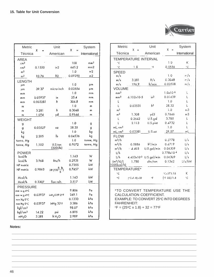
15. TABLE FOR UNIT CONVERSION ..............................................................................................................................46
26
1. INTRODUCTION
Carrier introduces its new family of liquid chillers designedto meet present and future needs of our customers.Our units feature:• Highly accurate and efficient Electronic Control• Refrigerant R-22• Lower transportation and installation costs• Screw compressors• Thermostatic expansion valve• A great variety of sizes• Flexibility of use
All units are equipped with the PRO-DIALOGPLUS NRCPcontrol system to optimize the efficiency of the chilling circuit.All units are also tested and charged with refrigerant HCFC22in our industrial plant.
2. CHARACTERISTICS
• High quality design and manufacture make the 30HKSthe liquid chiller of choice.
• The 30HKS units are furnished with screw compressors,designed to operate at very low noise and vibration levels.
• The 30HKS units exceed the ordinary efficiency figuresdemanded by industries both at full and partial capacities,cutting down your costs with electricity.
• The control in the 30HKS units is totally automatic. Theleaving water temperature is continually monitored todetect changes in capacity and flow. This arrangementmakes possible the most accurate temperature controlavailable today.
• Two independent cooling circuits are present: the secondcircuit starts operating immediately when the firstpresents problems, which maintains chilling at a partialcapacity regimen.
• Easy installation – the 30HKS Chillers are equipped withconveniently placed connections for total refrigerant load,power and water.
• Self-diagnosis – the current operational information isreadily displayed.
• The concept of multiple compressors improves efficiencyat partial capacities and lowers the start-up electriccurrent.
• Direct start-up.
2. 1. Easy installation
The 30GS units were given a compact design, which takesup minimum space in open areas and are also providedwith a complete installation package. There are no extracontrols, timers, start-up accessories, nor any other itemsthat require installation. The hydraulic connections are simplebecause flanges are used on the evaporator.
Water leavingcondenser
Liquid-state refrigerantfloods the sub-chiller.
Water flow direction
Inlet head
Sub-chillerinlet
Sub-chiller
Condensedrefrigerant
Condenser
3-passarrangement
Outlethead
2. 2. Simple maintenance
• Easy access to electric box and all its components.• Easy readings of suction and discharge pressures, along
with a specific display for temperature information.
2. 3. Liquid sub-chiller
Our units make use of the sub-chilling technique to improveefficiency, with the ultimate result of yielding greater coolingresults per kW consumed. The chilled water coming fromthe cooling tower enters the lowest point of the condensertube bundle (see drawing below).
27
2. 8. PRO-DIALOGPLUS NRCP control
The PRO-DIALOGPLUS NRCP control is an advancednumerical control system that combines knowledge andremarkable operational simplicity.
The PRO-DIALOGPLUS NRCP control guarantees sensiblecontrol of leaving water temperatures, thereby cutting downenergy costs.
• PID is an algorithm of permanent compensation controlfor the difference between inlet and outlet temperaturesat the heat exchanger. The method of calculationanticipates changes in capacity, securing constant outletwater temperatures and avoiding unnecessary compres-sor cycles.
• Several load capacity possibilities enable better start-upconditions at low outdoor air temperatures, and allowsone of the chilling circuits to be used as a stand-bysystem.
• Resetting of outlet water temperature is based on theoutdoor air temperature.
The new control system allows the user to program inadvance operational and non-operational periods for the unit.It enables the unit’s operational programming on a daily,monthly, yearly, and hourly basis.
2. 4. Easy compressor maintenance
The equipment is designed to ensure easy maintenanceand inspection routines for compressors. All you have to dois remove the bottom screws and snap the suction anddischarge nozzles to move the compressor.
2. 5. Drying filters
The chilling circuits are kept moisture-free to avoid problemswhen operating the system.
2. 6. Crankcase heaters
They help the compressors when they are not operating, toseparate refrigerant from oil, thus securing good lubricationwhen new start-up routines are necessary.
2. 7. Liquid sightglasses
Each chilling circuit is equipped with one sightglass toindicate the humidity in the system and therefore establishthe right time to replace filters.
28
For more details about the PRO-DIALOGPLUS NRCP control system please refer to the Control and TroubleshootingManual, no. 117.94.016.
The PRO-DIALOGPLUS NRCP control system offersextraordinary communication potentials.• The operational interface is clear and easily understood.
LEDs, numerical displays as well as the soft-touchswitches consent to real-time monitoring of operationalparameters such as pressure, temperature, andoperation schedules.
• The choice of a parallel Control is provided for two units(standard), or several units with the help of the FlotronicSystem Manager (FSM), and the Chiller System Manager(CSM III).
The PRO-DIALOGPLUS NRCP control system ensuresextra protection and extends the Chiller reliability.• Equalization of operational periods for each compres-
sor.• Absence of capillaries or pressure switches (except when
those are safety devices).
The PRO-DIALOGPLUS NRCP control system monitors allsafety parameters of the chiller. The failure history functionand the respective codes allow a given problem to be directlyspotted.
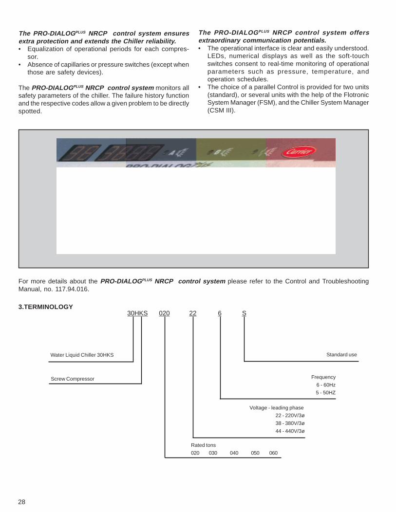
3.TERMINOLOGY30HKS 020 22 6 S
Standard use
Frequency
6 - 60Hz
5 - 50HZ
Voltage - leading phase
22 - 220V/3ø
38 - 380V/3ø
44 - 440V/3ø
Rated tons
020 030 040 050 060
Water Liquid Chiller 30HKS
Screw Compressor
29
020
15,9
20
811
17,5
-
2
-
2
50
100
-
-
50
234
0,016
219
1524
81
1587
5,89
1
2 NPT +
3/4 NPT
022
-
030
23,0
28
935
21,2
-
2
-
2
50
100
-
-
50
244
0,023
219
2108
81
2172
8,53
1
2 NPT +
3/4 NPT
027
-
040
30,9
38
1245
15,7
15,7
Screw
2
2
4
25
50
75
100
25
144
0,027
273
1829
129
1892
11,77
2
3 NPT +
3/4 NPT
022
022
050
38,1
47
1445
21,6
15,8
2
2
4
30,3
60,6
80,3
100
30,3
154
0,031
273
2108
129
2172
13,58
2
3 NPT +
3/4 NPT
027
022
060
44,1
54
1535
21,0
21,0
2
2
4
25
50
75
100
25
154
0,031
273
2108
129
2172
13,58
2
3 NPT +
3/4 NPT
027
027
4. PHYSICAL CHARACTERISTICS
Capacity control stage
(% cap. )
Ckt A
Ckt B
(quant.) Ckt A
(quant.) Ckt B
Ckt A
Ckt B
A1
A2
B1
B2
Unit 30HKS
Rated capacity (TR) 60Hz
Approx. Weight (kg)
Refrigerant Load (kg.) R-22
Compressor type*
Minimum capacity stage(%)
CHILLER
Chiller 10 HA400Carcass Liq. Vol. (m3)
Ext. diam. (mm)
Length (mm)
Cooling circuit
TubesQuantity
Length (mm)
Ext. area (m2)
Maximum pressure* (PSIG)
Water connections
Inlet and outlet
Flow*
CONDENSER 09RPCIRC A
CIRC B
+screw thread NTP tube
* refer to Table 8 for compressor models – electrical characteristics.
Select the model and the operational conditions demandedto meet the following design specifications:
Heat load ........................................... 25TR (75600 Kcal/h)Outlet chilled water temperature (T1) ...................... 7.0o CTemperature increment on inlet condenser water .... 5.5o CInlet water temperature (condenser) (T2) ................. 30o CChilled water flow ...................................................... 3.8 l/sCondensation water flow .......................................... 4.2 l/s
Set the temperature at 7.0o C (outlet chilled watertemperature) and 30o C (Inlet water temperature –condenser) on the table for unit 30HKS 030.
If T1 and T2 are not shown in the table, proceed as follows:
• If the chilled outlet temperature lies between 7 and 6o C(6.3o C, for instance), interpolate the data between thecolumn for overheating at 4o C / T1 = 7o C / T2 = 30o C,and the column for overheating at 4o C / T1 = 6o C / T2 =30o C.
• If the water temperature entering the condenser is 33o C,for instance, interpolate the data between the column foroverheating at 4o C / T1 = 7o C / T2 = 30o C, and thecolumn for overheating at 4o C / T1 = 7o C / T2 = 35o C.
For the conditions above, the model chosen is 30HKS 030,operating under the following conditions:
Outlet chilled water temperature (T1) ..................... 7.0o CInlet water temperature (condenser) (T2) ................. 30o CEnergy consumption .......................................... 25,669 WCooling capacity ............................................... 28.24 TRsChilled water flow ....................................................4.27 l/sCondensation water flow ......................................... 5.32l/s
The performance tables given in the next pages are validfor the models 30HKS under the following conditions:
a) STD (Saturated Discharge Temperature) ....... ≤ 48.9o Cb) Scale factor for condenser and chiller. ..... 0.0001m2oC H/Kcalc) Undercooling ......................................................... 5.5o Cd) Chiller temperature differential ............................. 5.5o Ce)Difference between STD and Inlet water temperature(condenser) (T2) ..................................................... 11.3o C
NOTE: When the unit 30HKS is selected under conditionsother than ∆T = 11.3o C for item (e) above, use the curve tocorrect the values in the table of capacity.
CAPAC.
EER
∆T
Correction = value at the Table of Capacity (x) % of capacitycorrection (according to the curve above).
For a ∆T other than 11.3o C, correct the capacity and theEER according to the percentages (positive and negative)of the table above.
It is recommended that units should not exceed theundercooling limits:Minimum: 2.8o CMaximum 8.3o C
% C
OR
RE
CT
ION
40
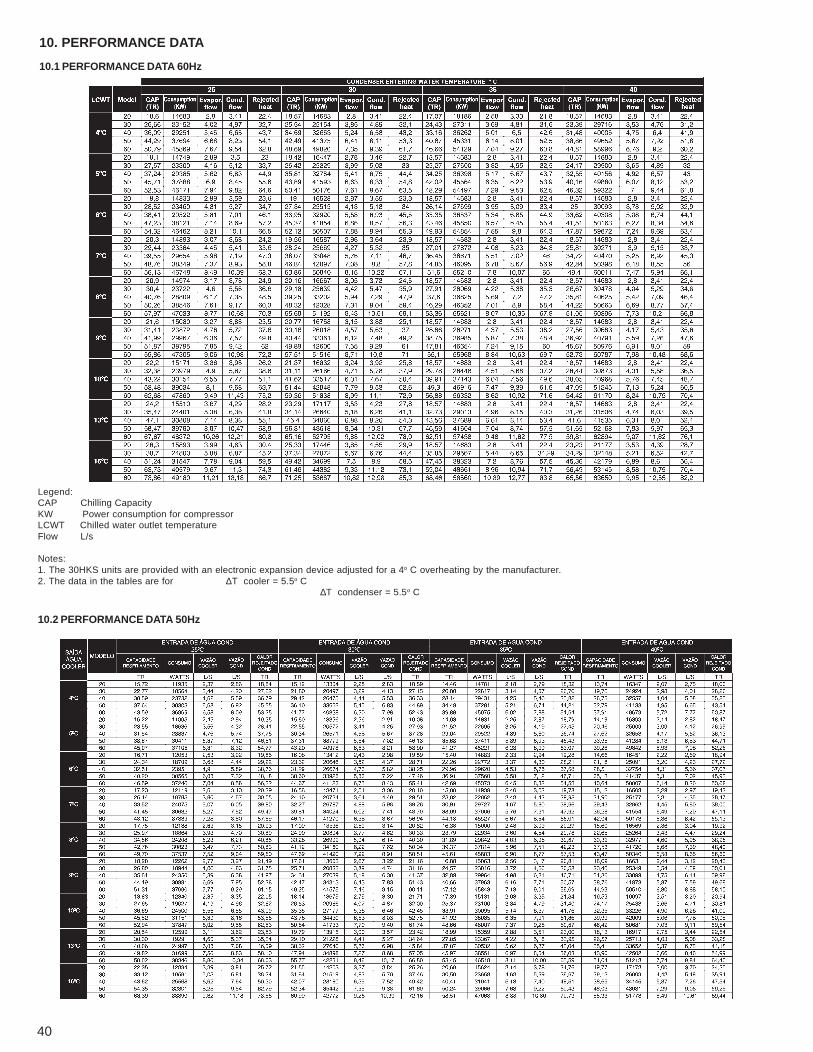
10. PERFORMANCE DATA
10.1 PERFORMANCE DATA 60Hz
Legend:CAP Chilling CapacityKW Power consumption for compressorLCWT Chilled water outlet temperatureFlow L/s
Notes:1. The 30HKS units are provided with an electronic expansion device adjusted for a 4o C overheating by the manufacturer.2. The data in the tables are for ∆T cooler = 5.5o C
∆T condenser = 5.5o C
10.2 PERFORMANCE DATA 50Hz
41
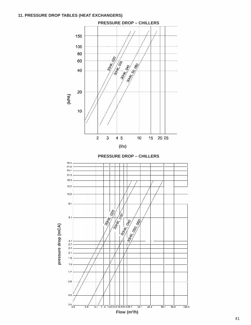
11. PRESSURE DROP TABLES (HEAT EXCHANGERS)
PRESSURE DROP – CHILLERS
PRESSURE DROP – CHILLERS
(l/s)
pre
ssu
re d
rop
(m
CA
)
Flow (m3/h)
(kPA
)
42
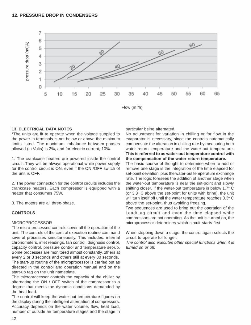
12. PRESSURE DROP IN CONDENSERS
pres
sure
dro
p (m
CA
)
Flow (m3/h)
13. ELECTRICAL DATA NOTES*The units are fit to operate when the voltage supplied tothe power-in terminals is not below or above the minimumlimits listed. The maximum imbalance between phasesallowed (in Volts) is 2%, and for electric current, 10%.
1. The crankcase heaters are powered inside the controlcircuit. They will be always operational while power supplyfor the control circuit is ON, even if the ON /OFF switch ofthe unit is OFF.
2. The power connection for the control circuits includes thecrankcase heaters. Each compressor is equipped with aheater that consumes 75W.
3. The motors are all three-phase.
CONTROLS
MICROPROCESSORThe micro-processed controls cover all the operation of theunit. The controls of the central execution routine commandseveral processes simultaneously. This includes: internalchronometers, inlet readings, fan control, diagnosis control,capacity control, pressure control and temperature set-up.Some processes are monitored almost constantly, others atevery 2 or 3 seconds and others still at every 30 seconds.The start-up routine of the microprocessor is carried out asdirected in the control and operation manual and on thestart-up tag on the unit nameplate.The microprocessor controls the capacity of the chiller byalternating the ON / OFF switch of the compressor to adegree that meets the dynamic conditions demanded bythe heat load.The control will keep the water-out temperature figures onthe display during the intelligent alternation of compressors.Accuracy depends on the water volume, flow, heat load,number of outside air temperature stages and the stage in
particular being alternated.No adjustment for variation in chilling or for flow in theevaporator is necessary, since the controls automaticallycompensate the alteration in chilling rate by measuring bothwater return temperature and the water-out temperature.This is referred to as water-out temperature control withthe compensation of the water return temperature.The basic course of thought to determine when to add orremove one stage is the integration of the time elapsed forset-point deviation, plus the water-out temperature exchangerate. The logic foresees the addition of another stage whenthe water-out temperature is near the set-point and slowlyshifting closer. If the water-out temperature is below 1.7o C(or 3.3o C above the set-point for units with brine), the unitwill turn itself off until the water temperature reaches 3.3o Cabove the set-point, thus avoiding freezing.Two sequences are used to bring out the operation of theLead/Lag circuit and even the time elapsed whilecompressors are not operating. As the unit is turned on, themicroprocessor determines which circuit starts first.
When stepping down a stage, the control again selects thecircuit to operate for longer.The control also executes other special functions when it isturned on or off.
43
THERMISTORS / TRANSDUCERS
Two thermistors are used to send temperature values tothe microprocessor. A third thermistor, (RT10) may be usedas a remote temperature sensor to read the outside airtemperature (OAT).
Four transducers are used to measure the pressure in thesystem (see Operation and Troubleshooting Manual).
T1 = chilled water temperature leaving the evaporator.
T2 = temperature of the water entering the evaporator(return).
T10 = outside air temperature sensor.
CONTROL SEQUENCE
Turn-off cycle – during the cycle to turn off the crankcaseheaters are energized.
Start-up – after having been turned on, a pre-start proceduretakes place for 2 minutes. This happens for themicroprocessor self checking to self check and wait for thetemperature stabilization. The first circuit to start may becircuit A or circuit B (automatic Lead / Lag). The control ofthe load ramp limits the compressor load at start-up, andthe unnecessary use of the compressor. The microprocessorlimits the supply and therefore water temperature drops (onlyat start-up) at 0.60o C per minute.
CAPACITY CONTROL
At the first call to start the chilling, the microprocessor startsthe first compressor and the first stage of the main circuitfan. The crankcase heaters are de-energized when thecompressors start to operate. If more chilling is necessary,more compressors are turned on alternating the Lead / Lagcircuits. The speed at which the capacity is increased ordecreased is controlled by the extent in which thetemperature shifts away from the set-point and the rate atwhich chilled water changes its temperature.
As the need for chilling capacity diminishes, the circuits turnoff (or de-energize themselves) in a sequence that tries tobalance the operation time for each circuit.
ALARM CONDITIONS(LED’S SIGNALERS)
All safety devices in the chiller are operated via the com-pressor protection board. The high pressure switch turnsoff the compressor directly via the compressor protectionboard. As for the other safety devices the microprocessor:
(1) Makes the right decision at turning off a compressordue to safety failure or bad sensor reading, (2) signals thealarm on the display, and (3) shows the failure code on thedisplay.
The chiller remains on the safety mode until re-arming andonly then returns to normal control.
SAFETY DEVICE FOR REFRIGERANT HEAD LOSS
The device is started if the pressure in the system dropsbelow minimum.
CUT-OFF DUE TO HIGH PRESSURE
The pressure switch turns the compressor off if the dischargepressure of the compressor increases to 2937 kPa.
ANTI-RECYCLING OF THE COMPRESSOR
This function limits the extent in which compressors areinterchanged.
PROTECTION AGAINST NO FLOW
This protection is provided by the difference in thetemperature of the water entering and the water leaving theevaporator, as read by the sensors. This function operatesif the temperature difference is less than 1.8o C.
SENSOR FAILURE
The sensor failure is detected by the microprocessor.
DIAGNOSES
The microprocessor may be quickly tested (see Control andTroubleshooting Manual), without additional equipment ortools.
14. GUIDELINES FOR SPECIFICATIONS – 30HKS, 020to 060
Screw Compressor Air- and Water-Cooled LiquidChillersSizes from 20 to 60 tonCarrier Model number: 30 HKS
PART 1 – GENERAL CONSIDERATIONS
1.01 - SYSTEM DESCRIPTIONA - Water-cooled liquid chiller controlled by a
microprocessor using Screw compressor andthermostatic expansion valves.
1.02 - GUARANTEED QUALITYA - The unit must be chosen accordingly to AR 590-92
standard.B - The unit must be designed as directed by ASHRA-E
15, last revision, and ASME where appropriate.C - The unit must be fully tested inside the plant.
1.03. - RECEPTION, STORAGE AND HANDLINGA - The unit must be stored and handled as directed by
the manufacturer’s instructions.B - The controls of the unit must be able to resist storage
44
temperature of up to 85o C inside the controlcompartment, indefinitely.
PART 2 - PRODUCTS
2.01 - EquipmentA - General
The equipment is an air-cooled liquid chiller, with no extramachinery, factory- assembled. All wiring, piping,controllers, the refrigerant load and all the specialaccessories must be provided with the cabinet of theunit, before start-up.
B - The Cabinet1 - The cabinet is built in galvanized steel panels.2 - Surface preparation: the surface must be prepared
by blasting it with abrasive minimum degree SA 2.5.Cleaning after blasting must be made using drypressurized air free of oil.
3 - Painting starts with a shop-primer before 4 hours ofblasting. Final thickness of the paint layer must be30 µm.
C - Compressors1 - Single screw compressor.2 - Assembled on rubber pads to absorb vibrations.
D - Evaporator1 - Hull-and-pipe type, with removable cover.2 - The pipes must be internally stretched out without
copper joints and expanded against the mirror.3 - The evaporator is equipped with flange-type water
connections.4 - The carcass must be isolated with ¾ “ PVC foam (19
mm) maximum K factor = 0.040 W/m.K.5 - The design must include 2 refrigerant circuits with
independent direct expansion.6 - The evaporator must be tested and sealed as directed
by the ASME standards to ensure a refrigerant-sideoperation pressure of 1916 kPa, and minimum water-side pressure of 2068 kPa.
E - Condenser1 - The coil is air-cooled, with integral sub-cooler, built
with aluminum fins mechanically connected to thecopper pipes, without seams. The pipes are clean,dry and sealed.
2 - The air-cooled coils must undergo a test to detectleaking at 1034 kPa, and an operational test at 3013kPa.
F - Refrigeration ComponentsThe components of the refrigerant circuit must includea safety device on the highpressure side, service valves on the liquid line, dryingfilter with changeable cores,thermostatic expansion valve (TXV), and a completerefrigerant load.
G – Controls, safety and diagnosis1 – Controls
a) The following components must be included, with noexception:1. Microprocessor2. Control and power supply circuit terminals3. Synoptic board4. Thermistors and/or pressure transducers
b) The components must be able to perform the followingtasks:1. Automatic circuit Lead / Lag.2. Capacity control based on the chilled water-out
temperature and compensated by the rate at whichthe return water changes temperature.
3. Limitation of the load ramp of the chilled watertemperature at start-up to 0.56o C/min., to avoidblocking due to excessive demand at start-up.
4. Hourly-based timetable.5. Re-set of chilled water-out temperature based on the
return water temperature.6. Demand limit control at 2 points (zero to 100% each).
2 – Safetya. The unit must be equipped with thermistors and all
necessary components together with the control systemto supply the following protection items:1 - Protection against refrigerant head loss.2 - Detection of low water level.3 - Protection against low chilled water temperature (anti-
freezing).4 - Protection against high or low overheating.5 - Protection against low voltage to supply controls.6 - Visual alarm (light).7 - Pressure switch for high pressure.
b. The compressors and motors must be equipped with thefollowing protection items:1 - Pressure overload.2 - Electric overload due to the use of thermo-magnetic
contacts. The circuit breakers must open all electricphases if overload happens on any phase (one phaseonly condition).
3 – Diagnoses
a. The diagnostic display module must be able to show thesafety isolation by exhibiting a code that is explained onthe display.The information to be assessed is:1- Compressor lock-up.2- Refrigerant head loss.3- Low water flow.4- Protection against freezing on the evaporator.5- High or low overheating at suction.6- Inadequate operation of thermistors or transducers.7- Water-in and -out temperature.8- Pressure at the evaporator and compressor.9-All adjustment points.10- Hour.
b. The module in association with the compressor must alsobe able to show the results of an operational test to check
45
the operation of each switch, thermistor, fan, and com-pressor before the start-up of the chiller.
c. Send the results to an outside source.
H – Operational Characteristics1 - The unit must be able to start operation with the
water-in temperature at the evaporator of 35o C.2 - The control of the refrigerant capacity must be carried
out via the compressor.3 - Two refrigerant circuits must protect against total loss
of capacity.4 - The unit must be provided with the automatic Lead /
Lag option to automatically interchange the maincircuit, ensuring the balanced use of all compressors.
I – Motors1 - The motors of the compressors must be cooled by
suction gas flowing around the electric coils of themotor.
2 - The motors of the condenser fans must be three-phase, with shafts permanently lubricated and classB isolation.
J – Electrical conditions1 - The primary power supply (three phases) must be
connected to one only position, as indicated in theelectrical diagrams.
2 - The unit must be shipped with control and powerwiring installed by the manufacturer.
K – Special options
Contact the local Carrier sales representative to obtain theinformation on how to best apply the specified parameters.
1 - Optional material for the condenser coil: The unit mustbe supplied with a coil made with copper tubes andcopper fins.
2 - Brine-operating units: the unit must be supplied soas to operate with a chilled water-out temperature of9o C.
3 - One chilled water flow switch must be installed in thefield to detect low water flow.