Case Study: Formal Verification of an ATM Switch Fabric using VIS 5.1 (of 29) Page Introduction 5.2 VIS Tool 5.3 FairisleATM Switch Fabric 5.5 Verification Strategy 5.7 Verification by Model Checking 5.9 Enhancement Techniques for Model Checking 5.18 Verification by Equivalence Checking 5.24 Conclusions 5.27 References 5.29
Transcript
Case Study: Formal Verification of an ATM Switch Fabric using VIS
5.1 (of 29)
Page
Introduction 5.2VIS Tool 5.3Fairisle ATM Switch Fabric 5.5Verification Strategy 5.7Verification by Model Checking 5.9Enhancement Techniques for Model Checking 5.18Verification by Equivalence Checking 5.24Conclusions 5.27References 5.29
Introduction
5.2 (of 29)
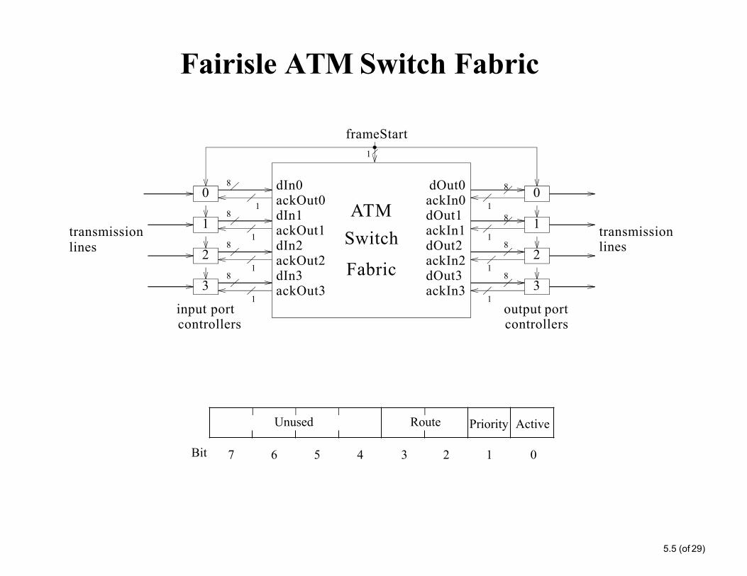
The Problem:• The need to produce high integrity communications systems
• ATM (Asynchronous Transfer Mode) switches are basic elements of state-of-the-art networks.
• Need a suitable technology to verify a whole ATM switch
Conventional Approaches:• Post-design Simulation, and Testing Cannot guarantee complete correctness
The Proposed Approach:
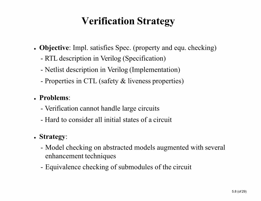
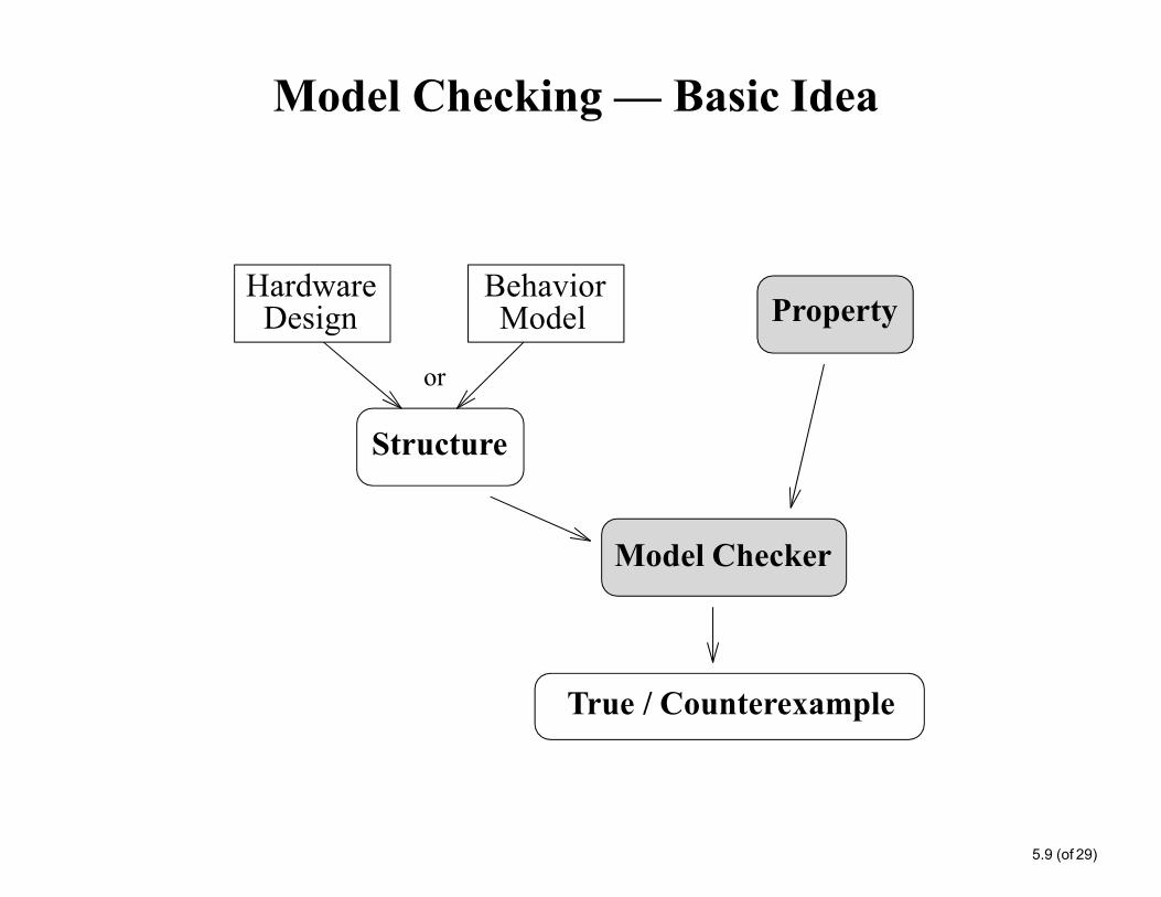
• Use Formal Verification based on Model Checking and Equivalence Checking in the VIS tool.
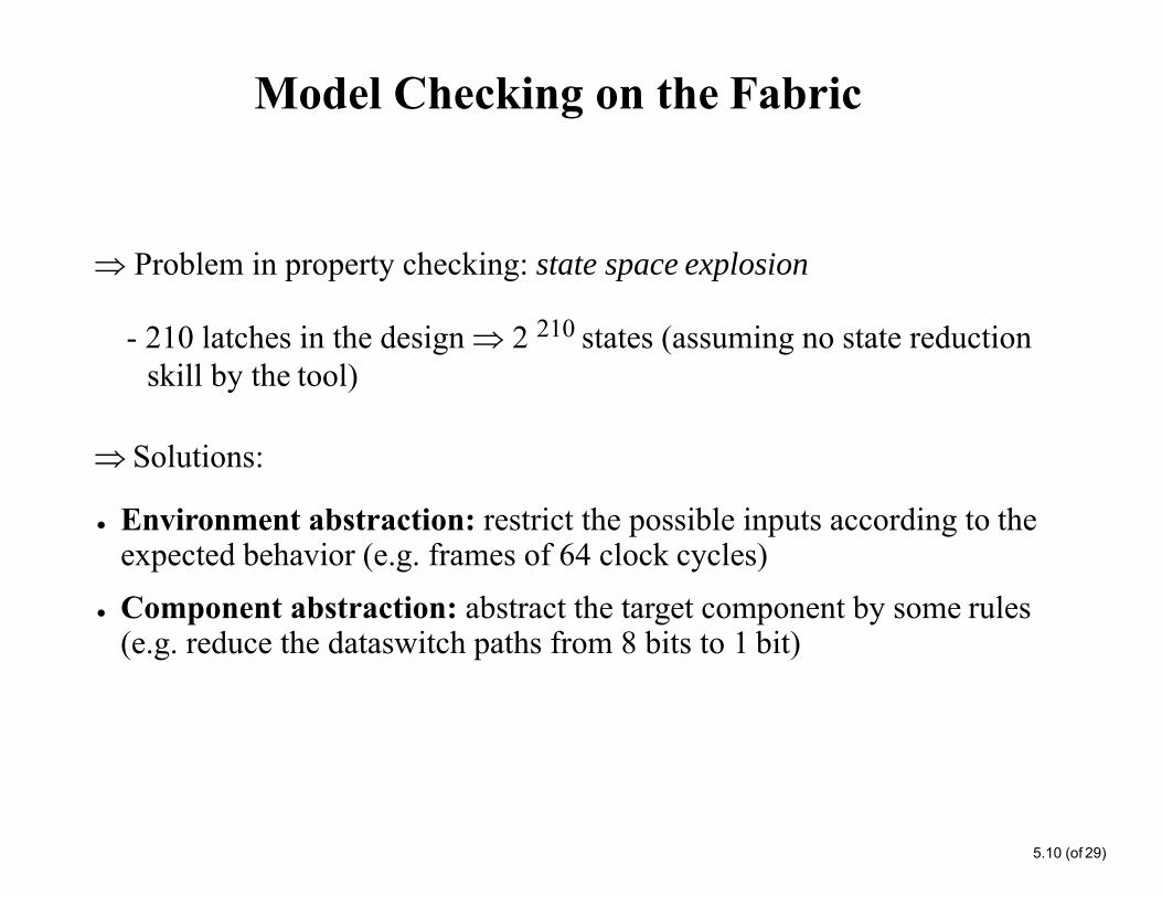
• Develop techniques to avoid state space explosion
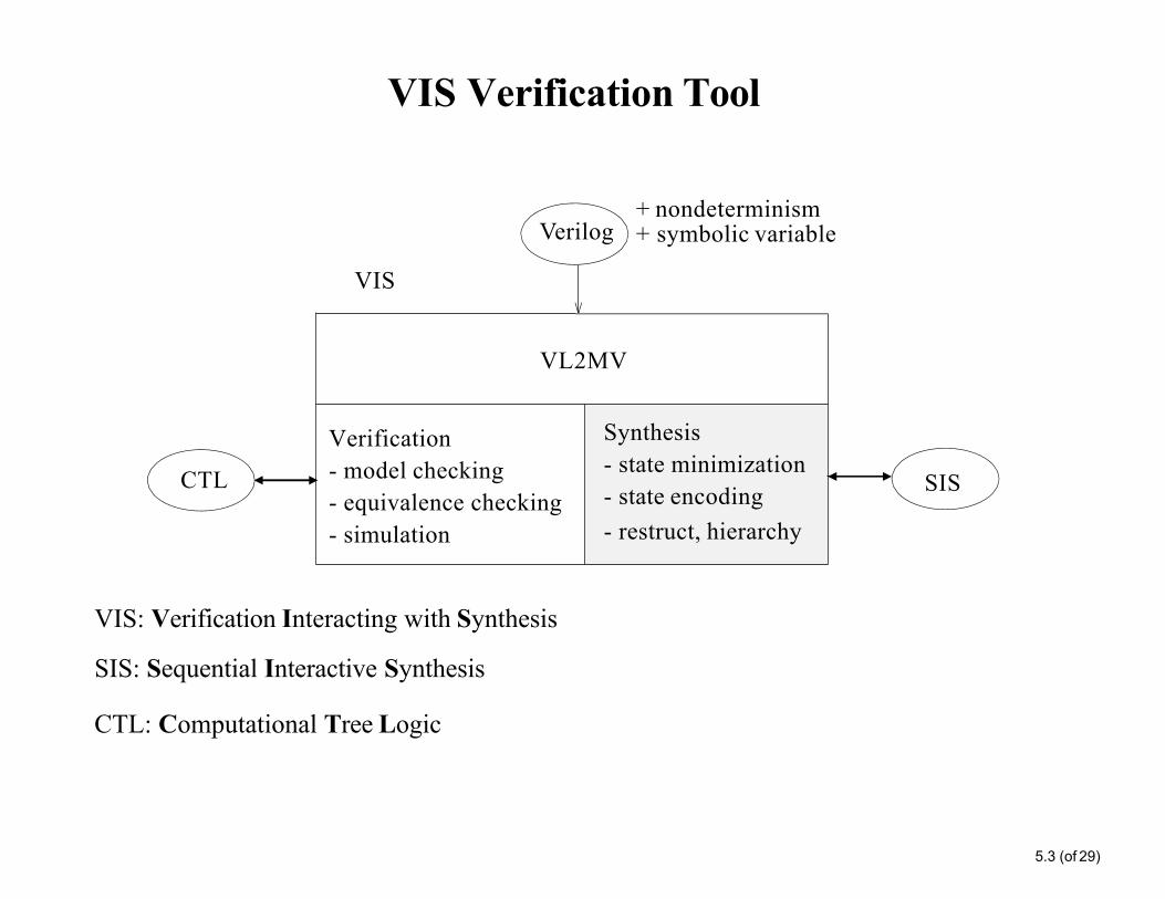
VIS
VL2MV
Verification- model checking- equivalence checking- simulation
Synthesis- state minimization- state encoding- restruct, hierarchy
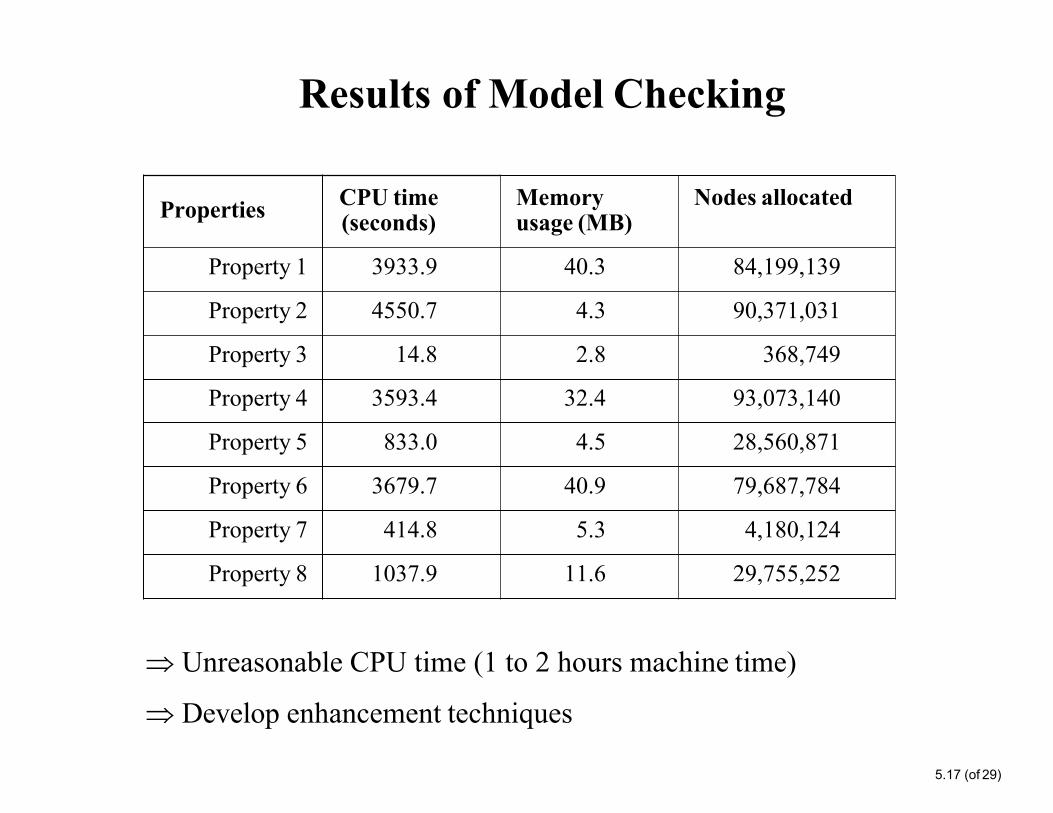
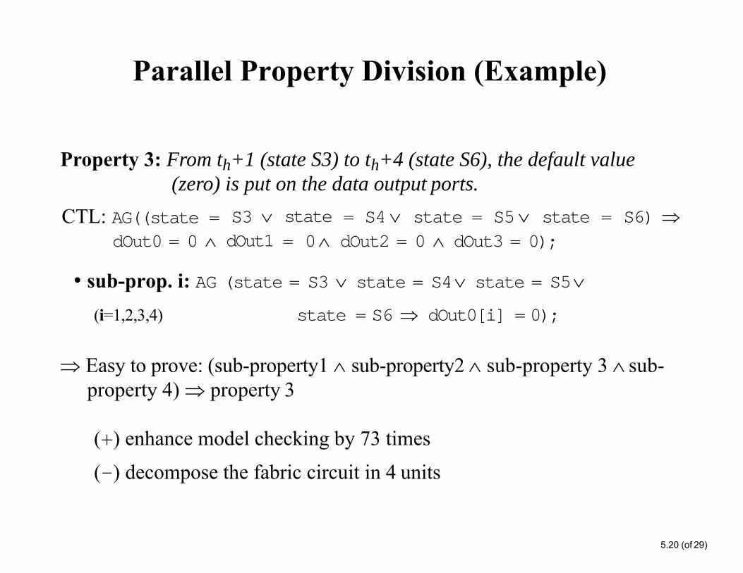
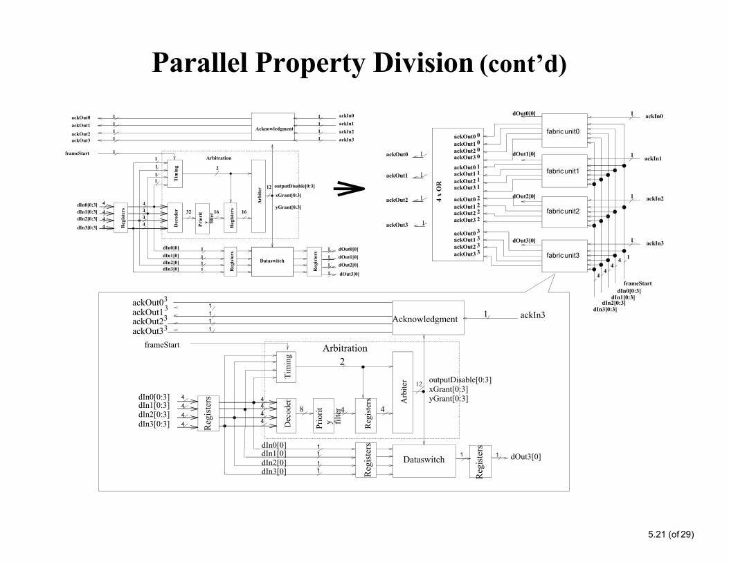
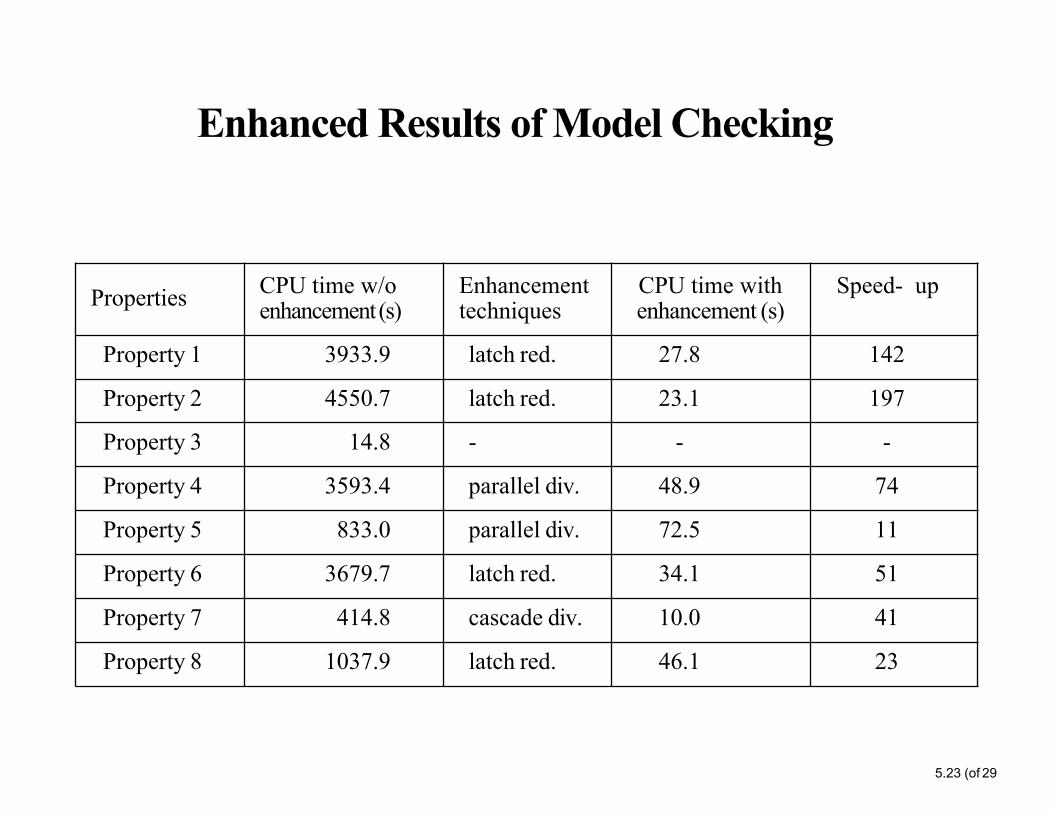
(+) enhance model checking by 73 times (-) decompose the fabric circuit in 4 units
Parallel Property Division (cont’d)
1
1
1
1
fabric unit0
fabric unit1
fabric unit2
fabric unit3
dOut0[0]
dOut1[0]
dOut2[0]4 x
OR
ackOut0 0ackOut1 0ackOut2 0ackOut3 0
ackOut0 1ackOut1 1ackOut2 1ackOut3 1
ackOut0 2ackOut1 2ackOut2 2ackOut3 2
ackOut0 3ackOut1 3ackOut2 3ackOut3 3
ackOut0 1
ackOut1 1
ackOut3
ackOut2 1
dOut3[0]
1
1
frameStart
dIn2[0:3]dIn3[0:3]
dIn0[0:3]dIn1[0:3]
44
44
ackIn0
ackIn1
ackIn2
ackIn3
1
Prio
rit
y filte
r
444
11111
1111
1
11
1111
1 dOut3[0]
ackOut0 ackOut1
ackOut2 ackOut3
1
4444
444
Arbitration
5.21 (of 29)
dIn0[0:3] 4dIn1[0:3]dIn2[0:3]dIn3[0:3]
dIn0[0]
dIn2[0]dIn3[0]
Tim
ing
Arb
iter
Reg
iste
rs
Prio
rity fil
ter
outputDisable[0:3] xGrant[0:3] yGrant[0:3]
11dIn1[0] 1
11
Dec
oder
1 dOut3[0]
2
12
8 4 4
Reg
iste
rs
Reg
iste
rs
Reg
iste
rs
ackIn31ackOut1 1ackOut03
3
ackOut23 1 AcknowledgmentackOut33 1
frameStart
Dataswitch
dIn0[0]dIn1[0]
dIn3[0]
xGrant[0:3]
yGrant[0:3]dIn0[0:3] 4
dIn1[0:3] 4dIn2[0:3] 4
dIn3[0:3] 4
Arbitration
161632
Dec
oder
Reg
iste
rsR
egis
ters
Reg
iste
rs
Tim
ing
Arb
iter
Reg
iste
rs
4
2
12 outputDisable[0:3]
frameStart
Dataswitch
ackIn0ackIn1ackIn2ackIn3
dIn2[0]
1 dOut0[0]1 dOut1[0]1 dOut2[0]
Acknowledgment
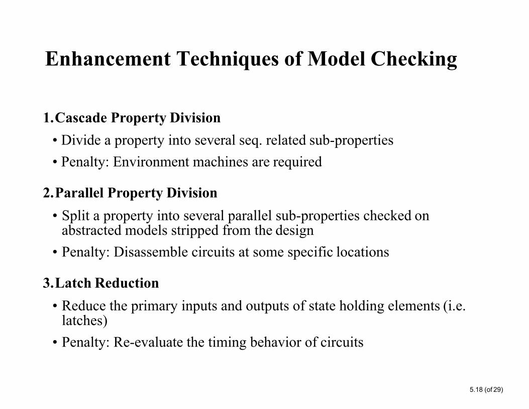
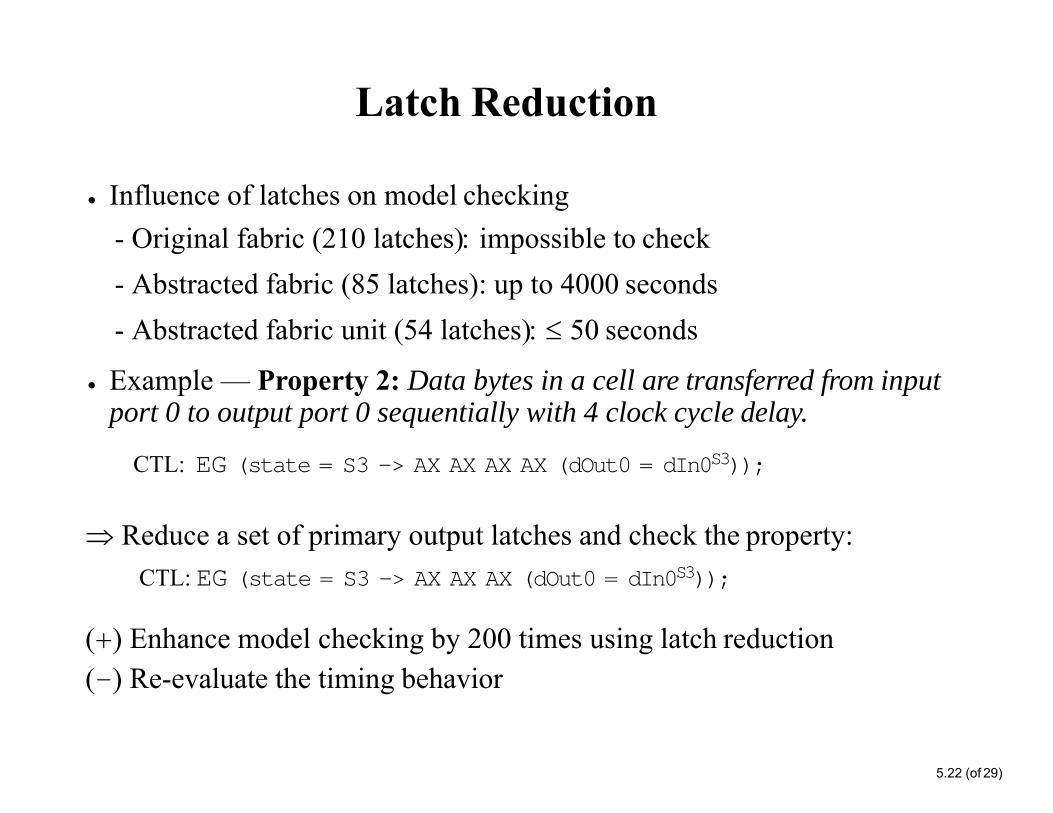
Latch Reduction
5.22 (of 29)
• Influence of latches on model checking- Original fabric (210 latches impossible to check- Abstracted fabric (85 latches): up to 4000 seconds- Abstracted fabric unit (54 latches) 50 seconds
• Example — Property 2: Data bytes in a cell are transferred from input port 0 to output port 0 sequentially with 4 clock cycle delay.
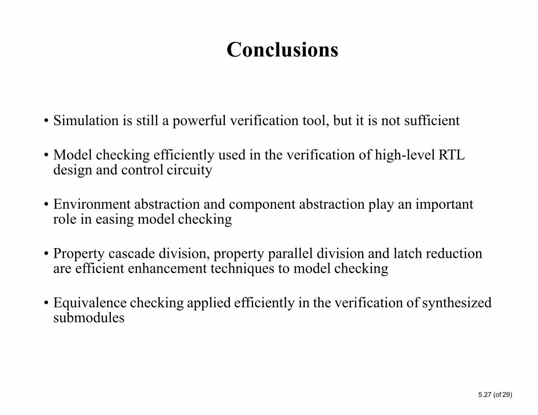
• Simulation is still a powerful verification tool, but it is not sufficient
• Model checking efficiently used in the verification of high-level RTL design and control circuity
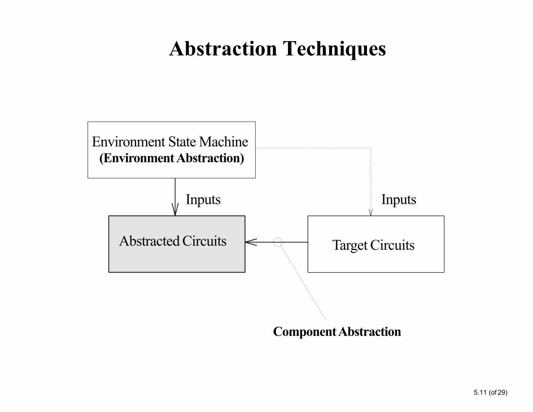
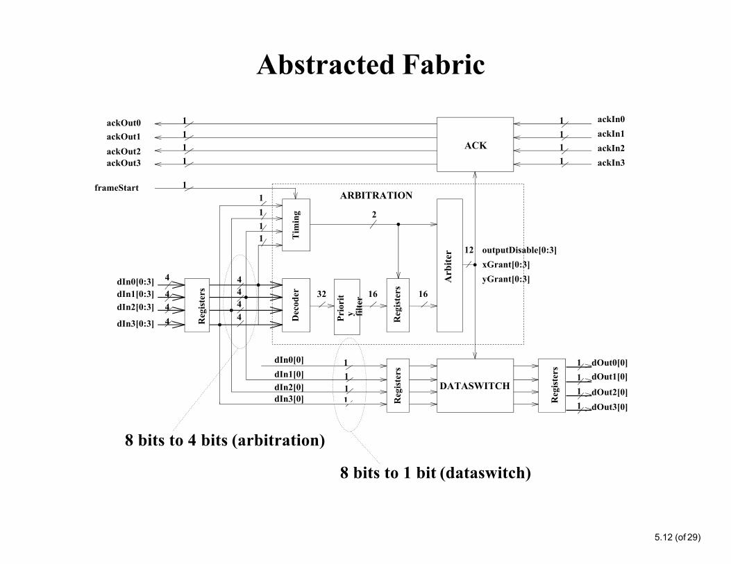
• Environment abstraction and component abstraction play an important role in easing model checking
• Property cascade division, property parallel division and latch reduction are efficient enhancement techniques to model checking
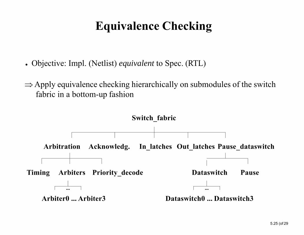
• Equivalence checking applied efficiently in the verification of synthesized submodules
Conclusions (cont‘d)
5.28 (of 29)
Human effort (not including time for learning the tool and development of abstraction/enhancement techniques):
The human time for formal verification is almost the same as that for simulation in a design.
Project phases Time(man-days) Code (# lines)
RTL description 10 580 (Verilog)
Netslist description 3 647 (Verilog)
Simulation 3 102 (testbench)
Model checking 3 200 (env. mach.)
Equivalence checking 1 0
Total 20 1529
References
5.29(of 29)
1. J. Lu and S. Tahar: Practical Approaches to the Automatic Verification of an ATM Switch Fabric using VIS; Proc. IEEE 8th Great Lakes Symposium on VLSI (GLS-VLSI'98), Lafayette, Louisiana, USA, February 1998, IEEE Computer Society Press, pp. 368-373.
2. J. Lu and S. Tahar: On the Formal Verification and Reimplementation of an ATM Switch Fabric Using VIS; Technical Report No. 401, Concordia University, Department of Electrical and Computer Engineering, September 1997.
3. Jianping Lu: On the Formal Verification of ATM Switches; MaSc Thesis, Concordia University, Department of Electrical and Computer Engineering, May 1999.
Technical report with source code available on-line at:http://hvg.ece.concordia.ca/Publications/TECH_REP/VIS_TR97/VIS_TR97.html
other papers on ATM switch verification can be found at:http://hvg.ece.concordia.ca/Research/APPL/atmsv.php