Page 1
1
DEPARTMENT OF
COMPUTER SCIENCE AND ENGINEERING
Case Tools and Software Testing
LAB MANUAL
By Divya Rao,Shilpa
B.Tech III Year, I Semester
COMPUTER SCIENCE AND ENGINEERING
Aurora’s Engineering College, parvathapur, Uppal, Dist., TS
Page 2
2
PART A: Case Tools List of Programs
Sl.No Name of the Experiment Page
No
1. Introduction to UML 4
2. Class Diagram for ATM 17
3. Use Case Diagram for ATM 19
4. Sequence Diagram for ATM 23
5. Collaboration Diagram for ATM 24
6. State chart Diagram for ATM 29
7. Activity Diagram for ATM 30
8. Component Diagram for ATM 35
9. Deployment Diagram for ATM 39
Page 3
3
PART B: Software Testing List of Programs
S. No Topic Page No.
1 Study of any testing tool (Win runner) Testing 40
2 Study of any web testing tool (Selenium) 50
3 Study of any bug tracking tool (Bugzilla, bugbit) 58
4 Study of any test management tool (test Director) 63
5 Study of any open source testing tool (Test Link) 69
Page 4
4
Introduction
CASE tools known as Computer-aided software engineering tools is a kind of component-
based development which allows its users to rapidly develop information systems. The main goal of
case technology is the automation of the entire information systems development life cycle process
using a set of integrated software tools, such as modeling, methodology and automatic code
generation. Component based manufacturing has several advantages over custom development. The
main advantages are the availability of high quality, defect free products at low cost and at a faster
time. The prefabricated components are customized as per the requirements of the customers. The
components used are pre-built, ready-tested and add value and differentiation by rapid customization
to the targeted customers. However the products we get from case tools are only a skeleton of the final
product required and a lot of programming must be done by hand to get a fully finished, good product.
Characteristics of CASE:
Some of the characteristics of case tools that make it better than customized development are;
It is a graphic oriented tool.
It supports decomposition of process.
Some typical CASE tools are:
Unified Modeling Language
Data modeling tools, and
Source code generation tools
UNIFIED MODELING LANGUAGE
Introduction
The unified modeling language (UML) is a standard language for writing software blue prints
of the system.
Definition:
The UML is a language for
• Visualizing
• Specifying
• Constructing
• Documenting
the artifacts of a software system.
Page 5
5
• UML is a language that provides vocabulary and the rules for combing words in that vocabulary
for the purpose of communication.
• Vocabulary and rules of a language tell us how to create and real well formed models, but they
don’t tell you what model you should create and when should create them.
Building Blocks of the UML:
The vocabulary of the UML encompasses three kinds of building blocks:
1. Things
2. Relationships
3. Diagrams
Things are abstractions that are first-class citizens in a model;
Relationships tie these things together;
Diagrams group interesting collections of things.
Things
Things are the most important building blocks of UML. There are four kinds of things in the UML.
1. Structural things
2. Behavioral things
3. Grouping things
4. Annotational things
1) STRUCTURAL THINGS:
Structural things are the nouns of the UML models.
These are static parts of the model, representing elements that are either conceptual or
physical.
There are seven kinds of Structural things.
1. Class
2. Interface
3. Collaboration
4. Use case
5. Active class
6. Component
7. Node
Page 6
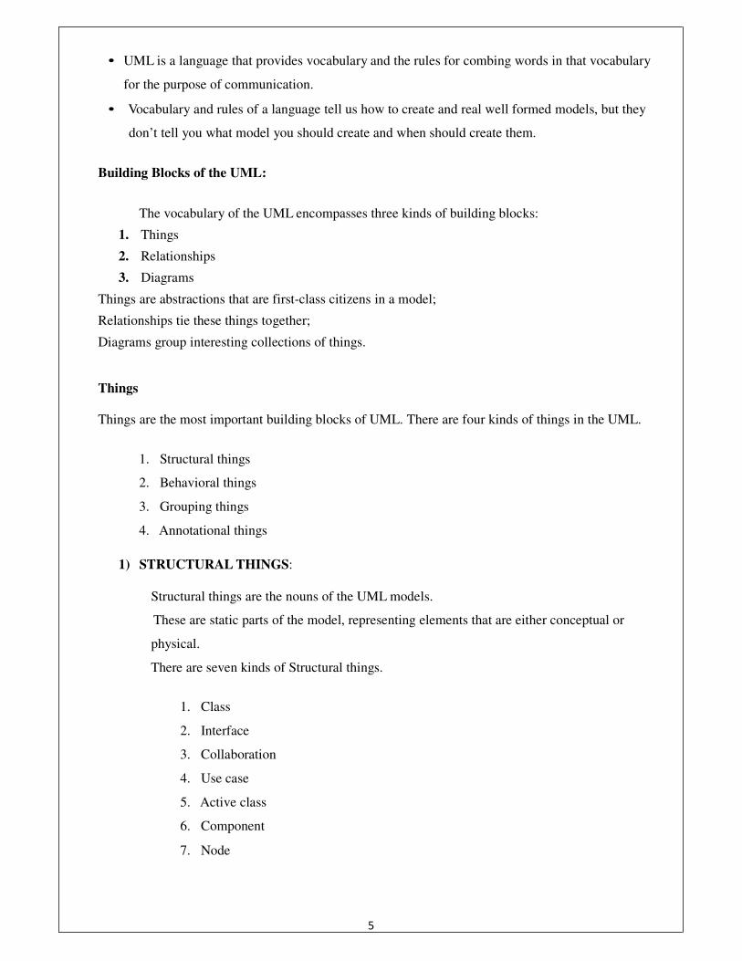
Class:
A class is a description of
relationships, and semantic
Graphically, a class is repre
operations, as shown below
W
Interface:
An interface is a collection
interface describes the exter
Graphically the interface is re
<<Interface>>
Mous eLis tener
(from event)
m ous eClicked() m
ous ePres s ed() m
ous eReleas ed() m
ous eEntered() m
ous eExited()
Collaboration:
Collaboration defines an in
together to provide some coop
Graphically, collaboration is
name as shown below.
Use Case:
Use case is a description of
goal for the system.
Graphically, Use Case is re
name as shown below.
of a set of objects that shares the common att
cs. A class implements one or more interfaces.
resented as a rectangle, usually including its n
w.
W in d o w
o ri g in
S ize
O p e n () C
los e () D
isp l a y ()
of operations that specify a service of a class
ernally visible behavior of that element.
rendered as a circle together with its name.
I Window
nteraction and is a society of roles and other
ooperative behavior that’s bigger than the sum of
s rendered as an ellipse with dashed lines, usuall
Chain of
Responsibility
of a set of sequence of actions performed by a sy
rendered as an ellipse with dashed lines, usually
Login
tributes, operations,
name, attributes and
s or component. An
elements that work
sum of all the elements.
ly including only its
ystem for a specific
y including only its
Page 7
7
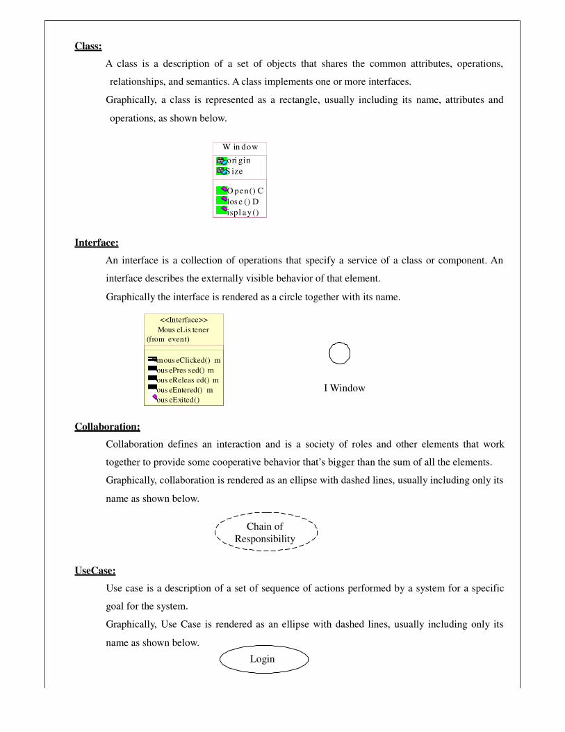
Active Class:
An active class is a class whose objects own one or more processes or threads and therefore
can initiate control activity.
Graphically, an active class is rendered just like a class, but with heavy lines usually including
its name, attributes and operations as shown below.
Event
Management
Suspend()
Flush()
Component:
Component is a physical and replaceable part of a system that conforms to and provides the
realization of a set of interfaces.
Graphically, a component is rendered as a rectangle with tabs, usually including only its name,
as shown below.
orderform.java
Node:
A Node is a physical element that exists at run time and represents a computational resource,
generally having at least some memory and often, processing capability.
Graphically, a node is rendered as a cube, usually including only its name, as shown below.
server
2) BEHAVIORAL THINGS:
Behavioral things are the dynamic parts of UML models.
These are the verbs of a model, representing behavior over time and space.
Page 8
8
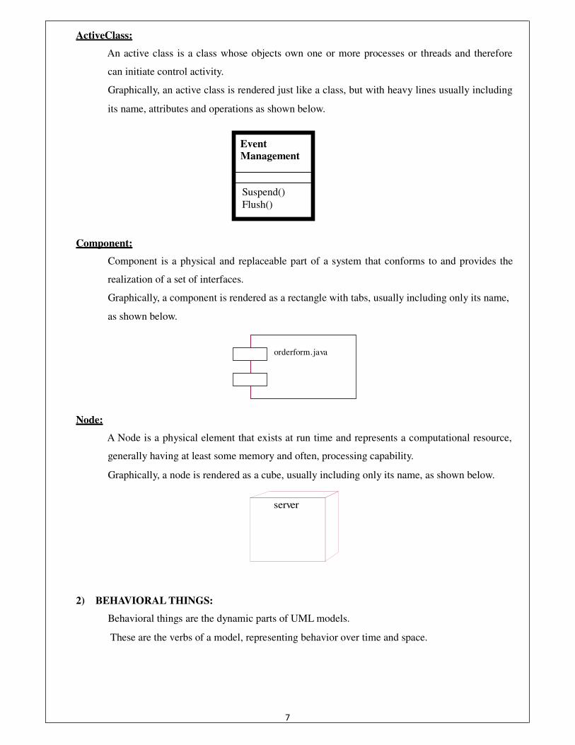
1) Interaction:
An interaction is a behavior that consists of a set of messages exchanged among a set of
objects(elements) within a particular context to accomplish a specific task.
Graphically, a message is rendered as a direct line, almost always including the name if its
operation, as shown below.
Display
2) State Machine:
A state machine is a behavior that specifies the sequence of states of an object in its life cycle.
It defines the sequence of states an object goes through in response to events.
Graphically, a state is rendered as a rounded rectangle usually including its name and its sub-
states, if any, as shown below.
Waiting
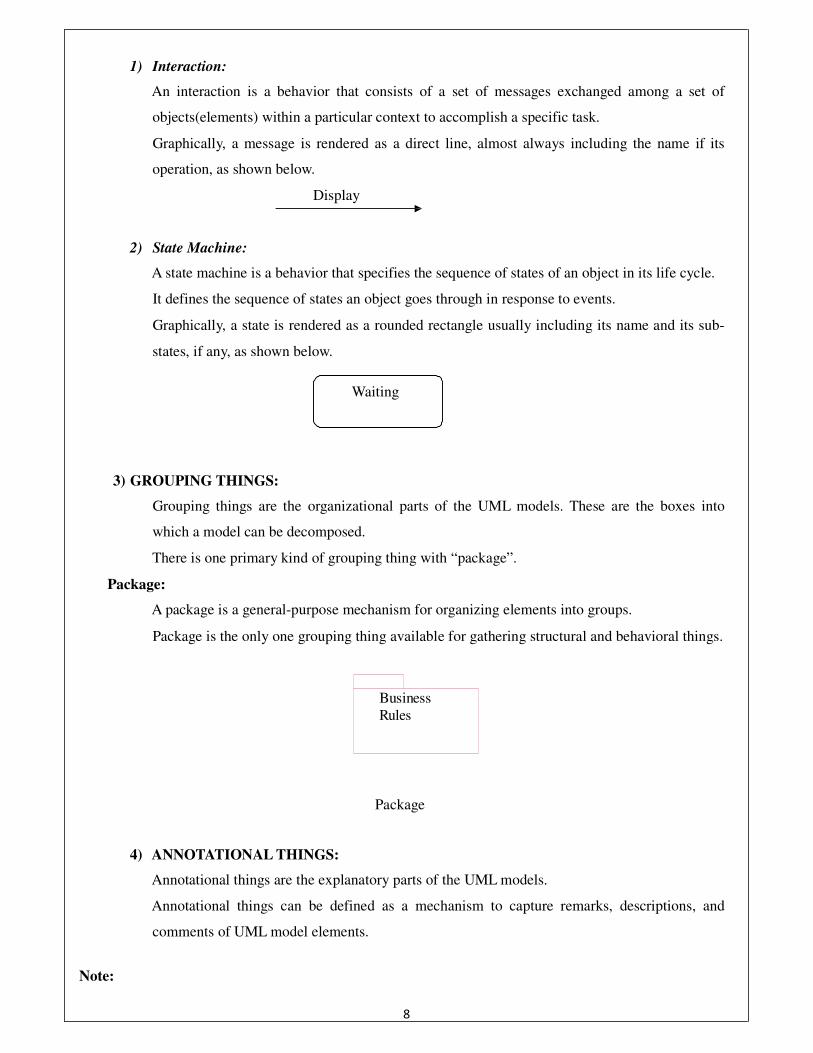
3) GROUPING THINGS:
Grouping things are the organizational parts of the UML models. These are the boxes into
which a model can be decomposed.
There is one primary kind of grouping thing with “package”.
Package:
A package is a general-purpose mechanism for organizing elements into groups.
Package is the only one grouping thing available for gathering structural and behavioral things.
Business
Rules
Package
4) ANNOTATIONAL THINGS:
Annotational things are the explanatory parts of the UML models.
Annotational things can be defined as a mechanism to capture remarks, descriptions, and
comments of UML model elements.
Note:
Page 9
A note is simply a symbol for rendering constraints and comments attached to an element or a
collection of elements.
Graphically a note is represented as a rectangle with dog-eared corner together, with a textual
or graphical comment, as shown below.
RELATIONSHIPS IN THE UML:
Note
Relationship is another most important building block of UML. It shows how elements
are associated with each other and this association describes the functionality of an
application. There are four kinds of relationships in the UML:
1. Dependency
2. Association
3. Generalization
4. Realization
Dependency
Dependency is a relationship between two things in which change in one element also
affects the other one.
Ex:
Dependency
Dependent Class Independent Classs
Association:
Association is basically a set of links that connects elements of an UML model. It also
describes how many objects are taking part in that relationship.
1 Multipicity
1..n
A B
Rolename Rolename
Association
Ex:
Page 10
10
1
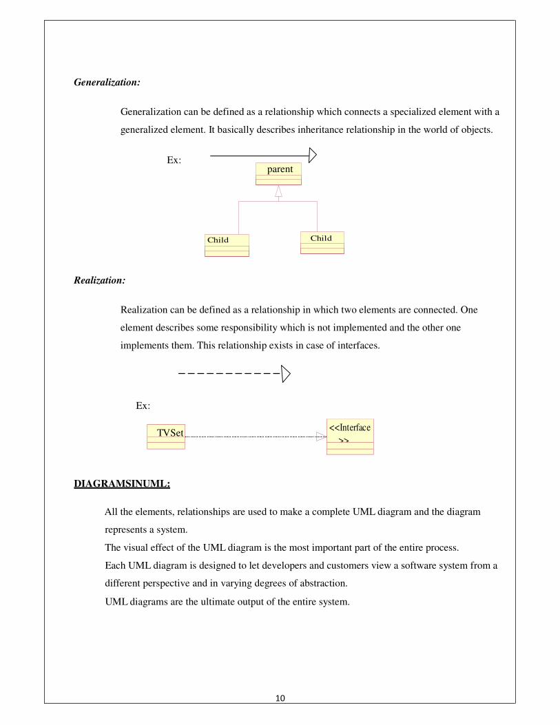
Generalization:
Generalization can be defined as a relationship which connects a specialized element with a
generalized element. It basically describes inheritance relationship in the world of objects.
Ex: parent
Child Child
Realization:
Realization can be defined as a relationship in which two elements are connected. One
element describes some responsibility which is not implemented and the other one
implements them. This relationship exists in case of interfaces.
Ex:
<<Interface
>> TVSet
DIAGRAMS IN UML:
All the elements, relationships are used to make a complete UML diagram and the diagram
represents a system.
The visual effect of the UML diagram is the most important part of the entire process.
Each UML diagram is designed to let developers and customers view a software system from a
different perspective and in varying degrees of abstraction.
UML diagrams are the ultimate output of the entire system.
Page 11
11
A diagram is the graphical presentation of a set of elements ,most often rendered as a
connected graph of vertices(things) arcs (relationships).
UML includes the following nine diagrams:
1) Class diagram
2) Object diagram
3) Use case diagram
4) Sequence diagram
5) Collaboration diagram
6) Activity diagram
7) State chart diagram
8) Deployment diagram
9) Component diagram
1. Class Diagram
Class diagram is a diagram that shows a set of classes, interfaces, and collaborations
and their relationships. Class diagrams address the static design view or the static process
view of the system.
Graphically it is represented as follows:-
School Department
student
2. Object Diagram
Object diagram shows a set of objects and their relationships. These diagram the static design
view or static process view of a system.
3. Usecase Diagram
Use Case diagram shows a set of use cases and actors (a special kind of class) and their relationships.
These diagrams address the static use case view of a system. Graphically it is represented as follows:-
User Book Issue
Page 12
12
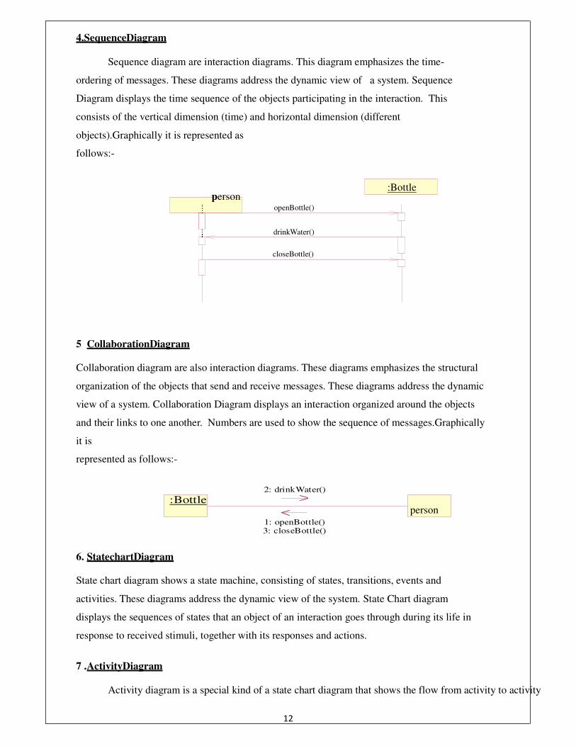
4. Sequence Diagram
Sequence diagram are interaction diagrams. This diagram emphasizes the time-
ordering of messages. These diagrams address the dynamic view of a system. Sequence
Diagram displays the time sequence of the objects participating in the interaction. This
consists of the vertical dimension (time) and horizontal dimension (different
objects).Graphically it is represented as
follows:- :Bottle person
openBottle()
drinkWater()
closeBottle()
5 Collaboration Diagram
Collaboration diagram are also interaction diagrams. These diagrams emphasizes the structural
organization of the objects that send and receive messages. These diagrams address the dynamic
view of a system. Collaboration Diagram displays an interaction organized around the objects
and their links to one another. Numbers are used to show the sequence of messages.Graphically
it is
represented as follows:-
2: drinkWater()
:Bottle person
1: openBottle() 3: closeBottle()
6. State chart Diagram
State chart diagram shows a state machine, consisting of states, transitions, events and
activities. These diagrams address the dynamic view of the system. State Chart diagram
displays the sequences of states that an object of an interaction goes through during its life in
response to received stimuli, together with its responses and actions.
7 .Activity Diagram
Activity diagram is a special kind of a state chart diagram that shows the flow from activity to activity
Page 13
13
state diagram where most of the states are action states and most of the transitions are triggered by
completion of the actions in the source states. Graphically it is represented as follows:-
8. Component Diagram
Component diagram shows the organizations and dependencies among a set of
components. These diagrams address the static implementation of view of a system. Component
Diagram displays the high level packaged structure of the code itself. Dependencies among
components are shown, including source code components, binary code components, and
executable components. Some components exist at compile time, at link time, at run times well
as at more
than one time.Graphically it is represented as follows:-
fraudagent.exe
fraudagent.dll
9. Deployment Diagram
Deployment diagram shows the configuration of run-time processing nodes and the components that
live on them. These diagrams address the static deployment view of architecture. Deployment Diagram
displays the configuration of run-time processing elements and the software components, processes,
and objects that live on them. Software component instances represent run-time
manifestations of code.
Graphically it is represented as follows:-
Admin
Client
admin.e
xe
<<10-T Ethernet>>
Server <<RS-
232>>
Exam
Client
Page 15
15
Automatic Teller Machine (ATM)
Description of ATM System
The software to be designed will control a simulated automated teller machine (ATM) having a
magnetic stripe reader for reading an ATM card, a customer console (keyboard and display) for
interaction with the customer, a slot for depositing envelopes, a dispenser for cash, a printer for
printing customer receipts, and a key-operated switch to allow an operator to start or stop the machine.
The ATM will communicate with the bank’s computer over an appropriate communication link. (The
software on the latter is not part of the requirements for this problem.)
The ATM will service one customer at a time. A customer will be required to insert an ATM card and
enter a personal identification number (PIN) – both of which will be sent to the bank for validation as
part of each transaction. The customer will then be able to perform one or more transactions. The card
will be retained in the machine until the customer indicates that he/she desires no further transactions,
at which point it will be returned – except as noted below.
The ATM must be able to provide the following services to the customer:
1. A customer must be able to make a cash withdrawal from any suitable account linked to the
card. Approval must be obtained from the bank before cash is dispensed.
2. A customer must be able to make a deposit to any account linked to the card, consisting of cash
and/or checks in an envelope. The customer will enter the amount of the deposit into the ATM,
subject to manual verification when the envelope is removed from the machine by an operator.
Approval must be obtained from the bank before physically accepting the envelope.
3. A customer must be able to make a transfer of money between any two accounts linked to the
card.
4. A customer must be able to make a balance inquiry of any account linked to the card.
5. A customer must be able to abort a transaction in progress by pressing the Cancel key instead
of responding to a request from the machine.
The ATM will communicate each transaction to the bank and obtain verification that it was allowed
by the bank. Ordinarily, a transaction will be considered complete by the bank once it has been
approved. In the case of a deposit, a second message will be sent to the bank indicating that the
customer has deposited the envelope. (If the customer fails to deposit the envelope within the timeout
period, or presses cancel instead, no second message will be sent to the bank and the deposit will not
be credited to the customer.)
Page 16
16
If the bank determines that the customer’s PIN is invalid, the customer will be required to re-enter the
PIN before a transaction can proceed. If the customer is unable to successfully enter the PIN after
three tries, the card will be permanently retained by the machine, and the customer will have to contact
the bank to get it back.
If a transaction fails for any reason other than an invalid PIN, the ATM will display an explanation of
the problem, and will then ask the customer whether he/she wants to do another transaction.
The ATM will provide the customer with a printed receipt for each successful transaction, showing the
date, time, machine location, type of transaction, account(s), amount, and ending and available
balance(s) of the affected account (“to” account for transfers).
The ATM will have a key-operated switch that will allow an operator to start and stop the servicing of
customers. After turning the switch to the “on” position, the operator will be required to verify and
enter the total cash on hand. The machine can only be turned off when it is not servicing a customer.
When the switch is moved to the “off” position, the machine will shut down, so that the operator may
remove deposit envelopes and reload the machine with cash, blank receipts, etc.
Objectives
The objective of this software is similar to ATM software installed in ATM center. It should
first validate the pin in the ATM card. Then the type of transaction is enquired and the information
from the customer is validated. If it is a withdrawal the amount is asked. After the money is delivered
the transaction just made is updated in the database where the customer’s information is stored.
Scope
The scope of the project is to design an ATM system that will help in completely automatic
banking this software is going to be designed for withdrawal and deposit of money and register the
transaction in the database where the customer’s information is stored.
Page 17
17
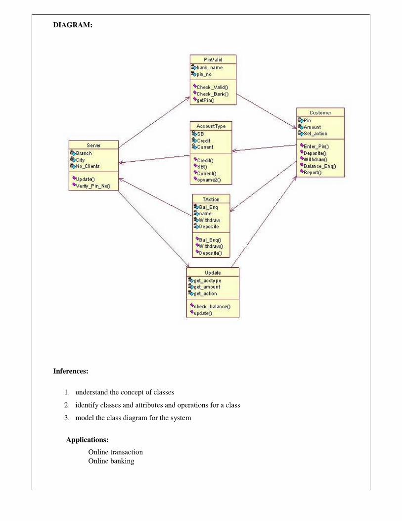
A) Name of the experiment: Class diagram for ATM System
1. AIM: To design and implement ATM system through Class Diagram
Purpose:
The purpose of the class diagram is to model the static view of an application. The class diagrams are
the only diagrams which can be directly mapped with object oriented languages and thus widely used
at the time of construction. The UML diagrams like activity diagram, sequence diagram can only give
the sequence flow of the application but class diagram is a bit different. So it is the most popular UML
diagram in the coder community. So the purpose of the class diagram can be summarized as:
• Analysis and design of the static view of an application.
• Describe responsibilities of a system.
• Base for component and deployment diagrams.
• Forward and reverse engineering.
Contents:
Class diagrams commonly contain the following things
• Classes
• Interfaces
• Collaborations
• Dependency, generalization and association relationships
Procedure:-
Step1: First Classes are created.
Step2: Named as PinValid, Account Type, Transaction, Update, Server, Customer classes are
created.
Step3: Appropriate relationships are provided between them as association.
Page 18
DIAGRAM:
Inferences:
1. understand the concept of classes
2. identify classes and attributes and operations for a class
3. model the class diagram for the system
Applications:
Online transaction
Online banking
Page 19
19
B) NAME OF EXPERIMENT: Use case diagram for ATM System.
AIM: To design and implement ATM System through Use case Diagram.
Purpose:
The purpose of use case diagram is to capture the dynamic aspect of a system. Because other four
diagrams (activity, sequence, collaboration and State chart) are also having the same purpose. So we
will look into some specific purpose which will distinguish it from other four diagrams. Use case
diagrams are used to gather the requirements of a system including internal and external influences.
These requirements are mostly design requirements. So when a system is analyzed to gather its
functionalities use cases are prepared and actors are identified.
So in brief, the purposes of use case diagrams can be as follows:
• Used to gather requirements of a system.
• Used to get an outside view of a system.
• Identify external and internal factors influencing the system.
• Show the interacting among the requirements are actors.
Procedure:
Step1: First an Actor is Created and named as User/Customer.
Step2: Secondly a system is created for ATM.
Step3: A use case Enter PIN, Withdraw money is created and connected with user as association
relationship.
Step4: Similarly various use cases like Deposit money, Balance Enquiry, Manage Account etc are
created and appropriate relationships are associated with each of them.
Page 20
DIAGRAM:
Customer
Withdrawal Use Case
A withdrawal transaction asks the c
checking) from a menu of possible acc
amounts. The system verifies that it h
the transaction to the bank. (If not, t
the transaction is approved by the b
before it issues a receipt. A withdrawa
Cancel key any time prior to choosi
Deposit Use Case
A deposit transaction asks the custom
a menu of possible accounts, and to
the bank to verify that the ATM can
Enter PIN
Withdraw Money
Balance enquiry
Deposit
Abort/ Cancel
Print Receipt
Manage Account
customer to choose a type of account to withdraw
accounts, and to choose an amount from a menu of
t has sufficient money on hand to satisfy the requ
the customer is informed and asked to enter a di
bank, the appropriate amount of cash is dispensed
rawal transaction can be cancelled by the custome
ing the amount.
omer to choose a type of account to deposit to (e.
o type in amount on the keyboard. The transaction
n accept a deposit from this customer to this accoun
ATM admin
w from (e.g.
nu of possible
quest before sending
ifferent amount.) If
d by the machine
er pressing the
.g. checking) from
on is initially sent to
ount. If the
Page 21
21
transaction is approved, the machine accepts an envelope from the customer containing cash and/or
checks before it issues a receipt. Once the envelope has been received, a second message is sent to the
bank, to confirm that the bank can credit the customer’s account – contingent on manual verification
of the deposit envelope contents by an operator later.
A deposit transaction can be cancelled by the customer pressing the Cancel key any time prior to
inserting the envelope containing the deposit. The transaction is automatically cancelled if the
customer fails to insert the envelope containing the deposit within a reasonable period of time after
being asked to do so.
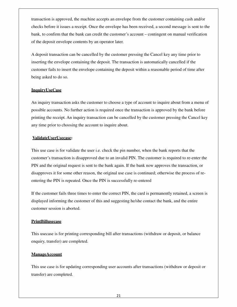
Inquiry Use Case
An inquiry transaction asks the customer to choose a type of account to inquire about from a menu of
possible accounts. No further action is required once the transaction is approved by the bank before
printing the receipt. An inquiry transaction can be cancelled by the customer pressing the Cancel key
any time prior to choosing the account to inquire about.
Validate User Use case:
This use case is for validate the user i.e. check the pin number, when the bank reports that the
customer’s transaction is disapproved due to an invalid PIN. The customer is required to re-enter the
PIN and the original request is sent to the bank again. If the bank now approves the transaction, or
disapproves it for some other reason, the original use case is continued; otherwise the process of re-
entering the PIN is repeated. Once the PIN is successfully re-entered
If the customer fails three times to enter the correct PIN, the card is permanently retained, a screen is
displayed informing the customer of this and suggesting he/she contact the bank, and the entire
customer session is aborted.
PrintBill usecase
This usecase is for printing corresponding bill after transactions (withdraw or deposit, or balance
enquiry, transfer) are completed.
Manage Account
This use case is for updating corresponding user accounts after transactions (withdraw or deposit or
transfer) are completed.
Page 22
22
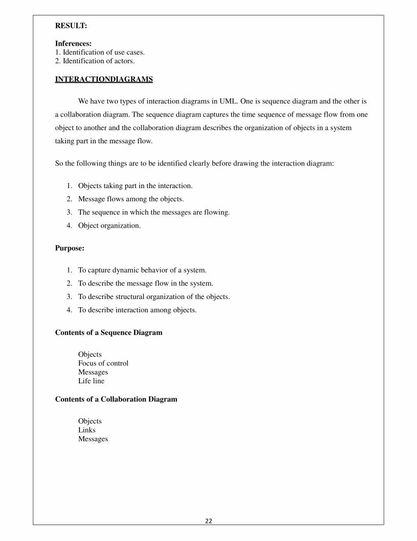
RESULT:
Inferences: 1. Identification of use cases. 2. Identification of actors.
INTERACTION DIAGRAMS
We have two types of interaction diagrams in UML. One is sequence diagram and the other is
a collaboration diagram. The sequence diagram captures the time sequence of message flow from one
object to another and the collaboration diagram describes the organization of objects in a system
taking part in the message flow.
So the following things are to be identified clearly before drawing the interaction diagram:
1. Objects taking part in the interaction.
2. Message flows among the objects.
3. The sequence in which the messages are flowing.
4. Object organization.
Purpose:
1. To capture dynamic behavior of a system.
2. To describe the message flow in the system.
3. To describe structural organization of the objects.
4. To describe interaction among objects.
Contents of a Sequence Diagram
Objects
Focus of control
Messages
Life line
Contents of a Collaboration Diagram
Objects
Links
Messages
Page 23
23
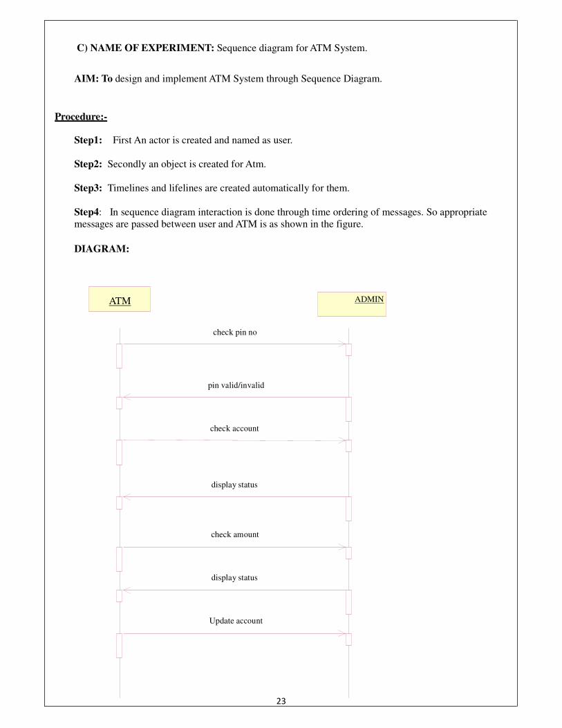
C) NAME OF EXPERIMENT: Sequence diagram for ATM System.
AIM: To design and implement ATM System through Sequence Diagram.
Procedure:-
Step1: First An actor is created and named as user.
Step2: Secondly an object is created for Atm.
Step3: Timelines and lifelines are created automatically for them.
Step4: In sequence diagram interaction is done through time ordering of messages. So appropriate
messages are passed between user and ATM is as shown in the figure.
DIAGRAM:
ATM ADMIN
check pin no
pin valid/invalid
check account
display status
check amount
display status
Update account
Page 24
24
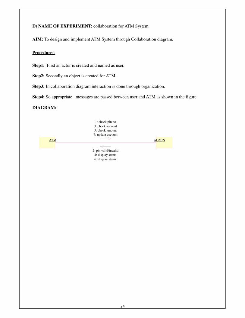
D) NAME OF EXPERIMENT: collaboration for ATM System.
AIM: To design and implement ATM System through Collaboration diagram.
Procedure:-
Step1: First an actor is created and named as user.
Step2: Secondly an object is created for ATM.
Step3: In collaboration diagram interaction is done through organization.
Step4: So appropriate messages are passed between user and ATM as shown in the figure.
DIAGRAM:
1: check pin no
3: check account
5: check amount
7: update account
ATM ADMIN
2: pin valid/invalid
4: display status
6: display status
Page 25
25
WITHDRAW Use Case:
SEQUENCE DIAGRAM
customer : ATM
machine
: Bank server
1: Insert Card
2: Validate Pin
3: Validate
4: Choose Transaction
5: Withdraw 6: Check Balance
7: Sufficiant Balance
8: Creadit cash
9: Insufficiant Balance
10: Low balance
COLLABORATION DIAGRAM
custome
r 1: Insert Card
4: Choose Transaction
5: Withdraw
8: Creadit cash
10: Low balance
: ATM
machine
3: Validate
7: Sufficiant Balance
9: Insufficiant Balance
2: Validate Pin
6: Check Balance
: Bank
server
Page 26
26
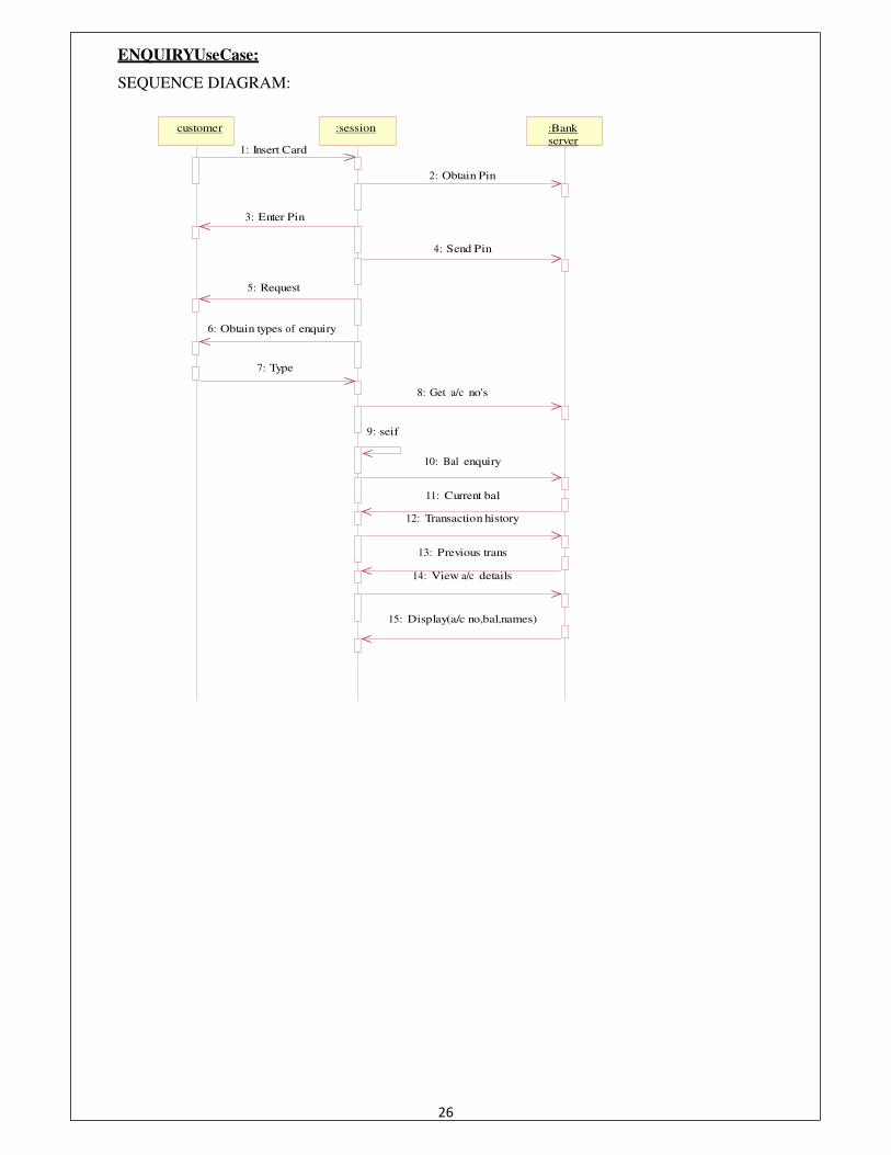
ENQUIRY UseCase:
SEQUENCE DIAGRAM:
customer
1: Insert Card
: session : Bank server
2: Obtain Pin
3: Enter Pin
4: Send Pin
5: Request
6: Obtain types of enquiry
7: Type
8: Get a/c no's
9: seif
10: Bal enquiry
11: Current bal
12: Transaction history
13: Previous trans
14: View a/c details
15: Display(a/c no,bal,names)
Page 27
27
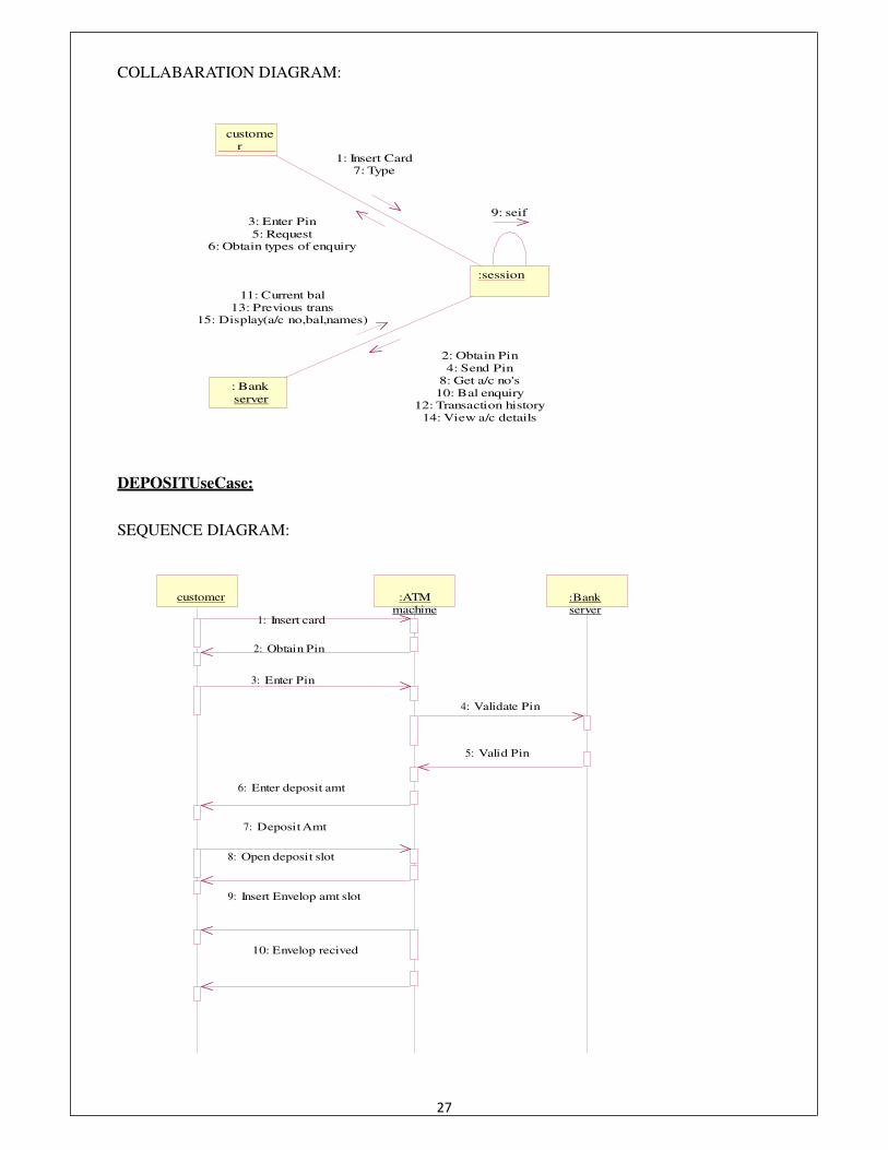
COLLABARATION DIAGRAM:
custome
r
1: Insert Card
7: Type
3: Enter Pin
5: Request 6: Obtain types of enquiry
9: seif
11: Current bal
13: Previous trans 15: Display(a/c no,bal,names)
: session
: Bank
server
2: Obtain Pin
4: Send Pin 8: Get a/c no's
10: Bal enquiry 12: Transaction history
14: View a/c details
DEPOSIT Use Case :
SEQUENCE DIAGRAM:
customer
1: Insert card
: ATM
machine : Bank server
2: Obtain Pin
3: Enter Pin
4: Validate Pin
5: Valid Pin
6: Enter deposit amt
7: Deposit Amt
8: Open deposit slot
9: Insert Envelop amt slot
10: Envelop recived
Page 28
28
COLLABARATION DIAGRAM:
custome
r
1: Insert card
3: Enter Pin
7: Deposit Amt
2: Obtain Pin
6: Enter deposit amt
8: Open deposit slot
9: Insert Envelop amt slot
10: Envelop recived
: ATM
machine
5: Valid Pin 4: Validate Pin
: Bank
server
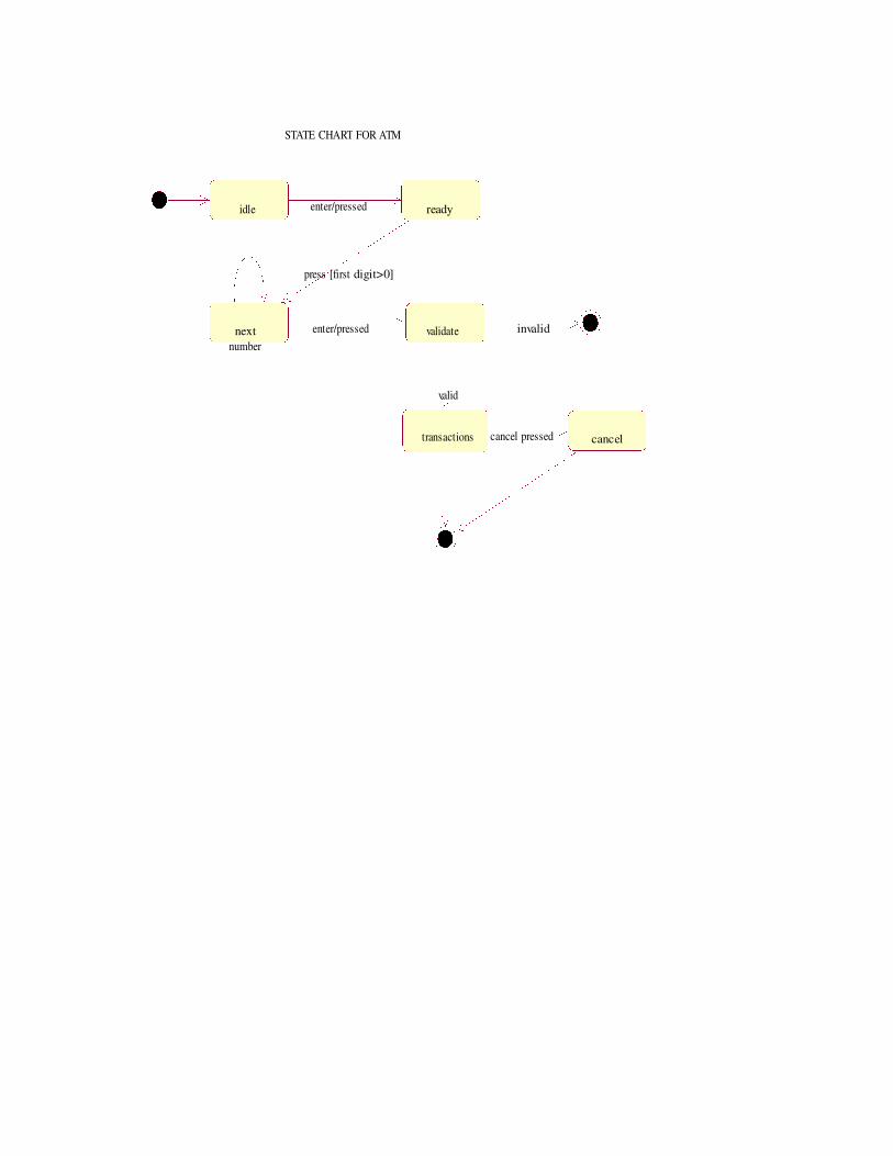
STATE CHART Diagram
State Chart diagram is used to model dynamic nature of a system. They define different states of an
object during its lifetime. And these states are changed by events. State chart diagram describes the
flow of control from one state to another state.
States are defined as a condition in which an object exists and it changes when some event is
triggered. But the main purpose is to model reactive system.
Contents
• Simply state and composite states
• Transitions, including events and actions
Page 29
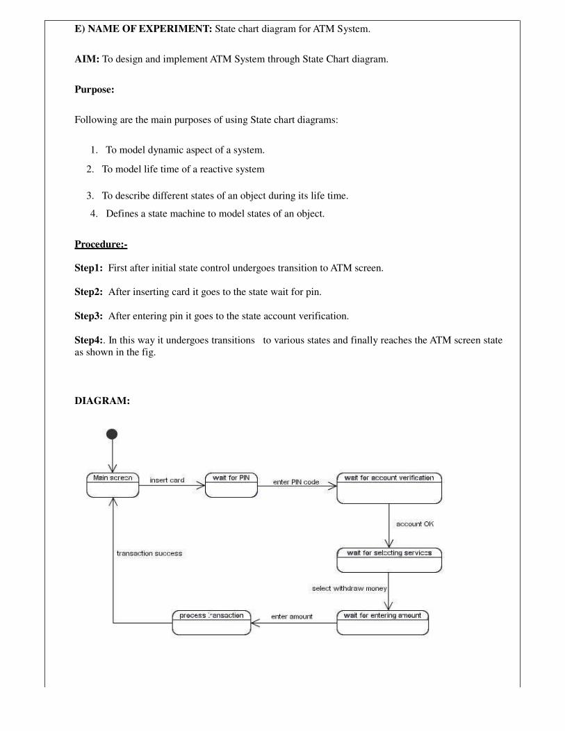
E) NAME OF EXPERIMENT: State chart diagram for ATM System.
AIM: To design and implement ATM System through State Chart diagram.
Purpose:
Following are the main purposes of using State chart diagrams:
1. To model dynamic aspect of a system.
2. To model life time of a reactive system
3. To describe different states of an object during its life time.
4. Defines a state machine to model states of an object.
Procedure:-
Step1: First after initial state control undergoes transition to ATM screen.
Step2: After inserting card it goes to the state wait for pin.
Step3: After entering pin it goes to the state account verification.
Step4:. In this way it undergoes transitions to various states and finally reaches the ATM screen state
as shown in the fig.
DIAGRAM:
Page 30
STATE CHART
idle enter/pres
press [first
next
number
enter/pres
T FOR ATM
ssed ready
digit>0]
ssed validate invalid
valid
transactions cancel pressed cancel
Page 31
31
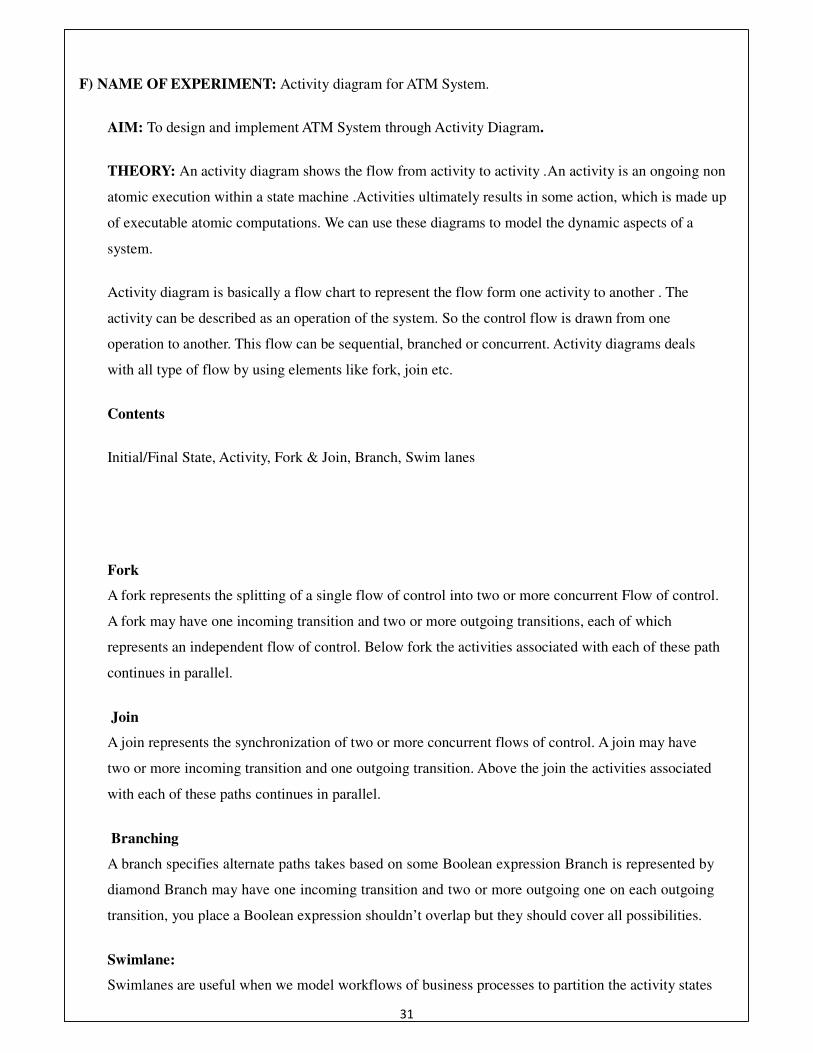
F) NAME OF EXPERIMENT: Activity diagram for ATM System.
AIM: To design and implement ATM System through Activity Diagram.
THEORY: An activity diagram shows the flow from activity to activity .An activity is an ongoing non
atomic execution within a state machine .Activities ultimately results in some action, which is made up
of executable atomic computations. We can use these diagrams to model the dynamic aspects of a
system.
Activity diagram is basically a flow chart to represent the flow form one activity to another . The
activity can be described as an operation of the system. So the control flow is drawn from one
operation to another. This flow can be sequential, branched or concurrent. Activity diagrams deals
with all type of flow by using elements like fork, join etc.
Contents
Initial/Final State, Activity, Fork & Join, Branch, Swim lanes
Fork
A fork represents the splitting of a single flow of control into two or more concurrent Flow of control.
A fork may have one incoming transition and two or more outgoing transitions, each of which
represents an independent flow of control. Below fork the activities associated with each of these path
continues in parallel.
Join
A join represents the synchronization of two or more concurrent flows of control. A join may have
two or more incoming transition and one outgoing transition. Above the join the activities associated
with each of these paths continues in parallel.
Branching
A branch specifies alternate paths takes based on some Boolean expression Branch is represented by
diamond Branch may have one incoming transition and two or more outgoing one on each outgoing
transition, you place a Boolean expression shouldn’t overlap but they should cover all possibilities.
Swimlane:
Swimlanes are useful when we model workflows of business processes to partition the activity states
Page 32
32
on an activity diagram into groups. Each group representing the business organization responsible for
those activities, these groups are called Swimlanes .
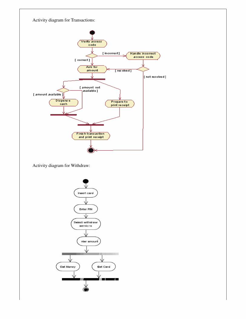
Procedure:-
Step1: First initial state is created.
Step2: After that it goes to the action state insert card.
Step3: Next it undergoes transition to the state enter pin
Step4: In this way it undergoes transitions to the various states.
Step5: Use forking and joining wherever necessary.
Page 33
Activity diagram for Transactions:
Activity diagram for Withdraw:
Page 34
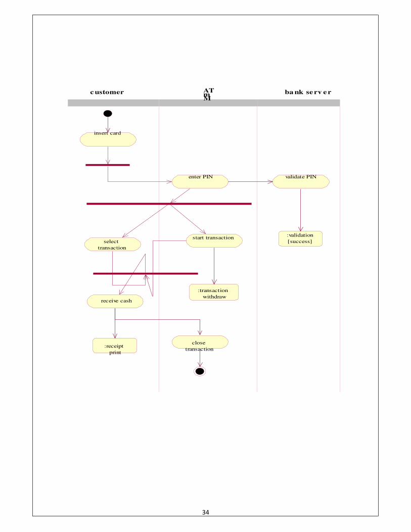
34
c ustomer ATmM
ba nk se rv e r
insert card
enter PIN validate PIN
select
transaction
start transaction
:validation
[success]
receive cash
:transaction
withdraw
:receipt
print
close
transaction
Page 35
35
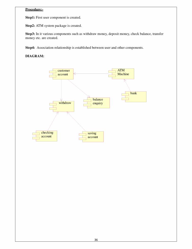
Inferences:
1. Identify the action states of the objects .
2. Understand the transitions and events for various objects.
G) NAME OF EXPERIMENT: Component diagram for ATM System.
AIM: To design and implement Component diagram for ATM System.
THEORY:
Component diagrams are used to model physical aspects of a system. Physical aspects are the
elements like executables, libraries, files, documents etc which resides in a node. So component
diagrams are used to visualize the organization and relationships among components in a system.
These diagrams are also used to make executable systems.
Purpose:
Component diagrams can be described as a static implementation view of a system. Static
implementation represents the organization of the components at a particular moment. A single
component diagram cannot represent the entire system but a collection of diagrams are used to
represent the whole.
Before drawing a component diagram the following artifacts are to be identified clearly:
• Files used in the system.
• Libraries and other artifacts relevant to the application.
• Relationships among the artifacts.
• Now after identifying the artifacts the following points needs to be followed:
• Use a meaningful name to identify the component for which the diagram is to be drawn.
• Prepare a mental layout before producing using tools.
• Use notes for clarifying important points.
Contents
Components, Interfaces, Relationships
Page 36
36
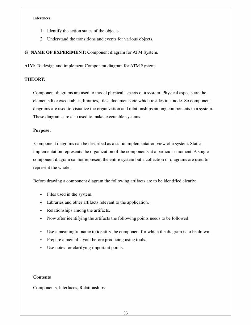
Procedure:-
Step1: First user component is created.
Step2: ATM system package is created.
Step3: In it various components such as withdraw money, deposit money, check balance, transfer
money etc. are created.
Step4: Association relationship is established between user and other components.
DIAGRAM:
customer account
ATM Machine
withdraw
balance enquiry
bank
checking account
saving account
Page 37
37
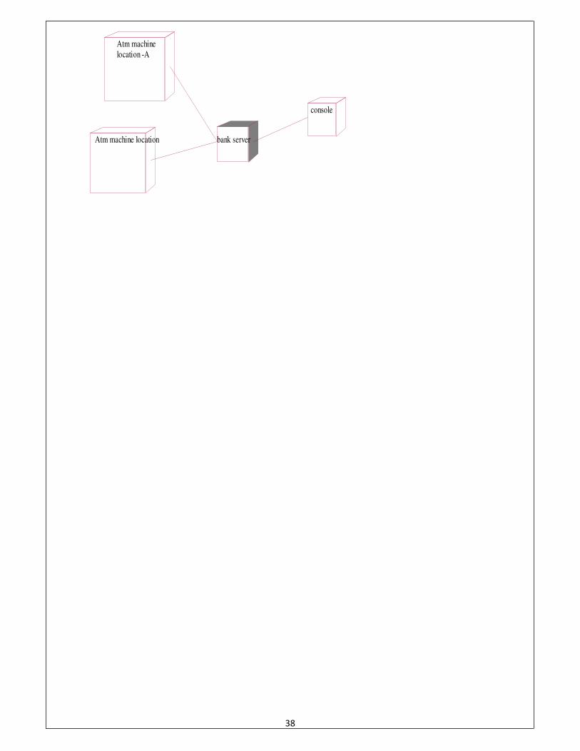
H) NAME OF EXPERIMENT: Deployment diagram for ATM System. AIM:
To design and implement ATM System through Deployment diagram. Purpose:
Deployment diagrams are used to visualize the topology of the physical components of a system
where the software components are deployed. So deployment diagrams are used to describe the static
deployment view of a system. Deployment diagrams are used for describing the hardware
components where software components are deployed. Component diagrams and deployment
diagrams are closely related. Component diagrams are used to describe the components and
deployment diagrams shows how they are deployed in hardware.
Contents: Nodes, Dependency & Association relationships
Procedure:-
Step1: First user node is created
Step2: various nodes withdraw money, deposit money, and check balance, transfer money etc.
are created.
Step4: Association relationship is established between user and other nodes.
Step5: Dependency is established between deposit money and check balance.
Page 38
38
Atm machine location -A
console
Atm machine location bank server
Page 39
39
Introduction to Testing Software testing is more than just error detection;
Testing software is operating the software under controlled conditions, to (1) verify that it
behaves “as specified”; (2) to detect errors, and (3) to validate that what has been specified is
what the user actually wanted.
1. Verification is the checking or testing of items, Including software, for conformance and
consistency by evaluating the results against pre-specified requirements.
2. Error Detection: Testing should intentionally attempt to make things go wrong to
determine if things happen when they shouldn’t or things don’t happen when they should.
3. Validation looks at the system correctness – i.e, is the process of checking that what has
been specified is what the user actually wanted.
In other words, validation checks to see if we are building what the customer wants/needs, and
verification checks to see if we are building that system correctly. Both verification and
validation are necessary, but different components of any testing activity.
The definition of testing according to the ANSI/IEEE 1059 standard is that testing is the process
of analyzing a software item to detect the differences between existing and required conditions
(that is defects/errors/bugs) and to evaluate the features of the software item.
Quality software is reasonably bug-free, delivered on time and within budget, meets
requirements and/or expectations, and is maintainable.
However, quality is a subjective term. It will depend on who the ‘customer’ is and their overall
influence in the scheme of things. A wide-angle view of the ‘customers’ of a software
development project might include end-users, customer acceptance testers, customer contract
officers, customer management, the development organization’s
management/accountants/testers/salespeople, future software maintenance engineers,
stockholders, magazine reviewers, etc. Each type of ‘customer’ will have their own view on
‘quality’ – the accounting department might define quality in terms of profits while an end-user
might define quality as user-friendly and bug-free.
Page 40
40
EXERCISE NO. 1 WINRUNNER
Introduction WinRunner, Mercury Interactive’s enterprise functional testing tool. It is used to quickly create
and run sophisticated automated tests on your application.
Winrunner helps you automate the testing process, from test development to execution. You
create adaptable and reusable test scripts that challenge the functionality of your application.
Prior to a software release, you can run these tests in a single overnight run- enabling you to
detect and ensure superior software quality.
Contents:
• Features
• Lab Exercises
• Check Points
• Synchronization Point
• GUI Spy
• Merge
• TSL Scripts
What’s New in Win Runner 7.5?
• Automatic Recovery
• The Recovery Manager provides an easy-to-use wizard that guides you through the
process of defining a recovery scenario.
• You can specify one or more operations that enable the test run to continue after an
exception event occurs. This functionality is especially useful during unattended test runs,
when errors or crashes could interrupt the testing process until manual intervention
occurs.
• Silent Installation
• Now you can install WinRunner in an unattended mode using previously recorded
installation preferences. This feature is especially beneficial for those who use enterprise
software management products or any automated software distribution mechanisms.
• Embanked Integration with Test Director
• WinRunner works with both test Director 6.0, which is client/server-based, and Test
Director 7.x, which is Web-based. When reporting defects from WinRunner’s test results
window, basic information about the test and any checkpoints can be automatically
populated in Test Directors’s defect form. WinRunner now supports version, control,
which enables updating and revising test scripts while maintaining old versions of each
test.
• Support for Terminal Servers
Page 41
41
• Support for Citrix and Microsoft Terminal Servers makes it possible to open several
window clients and run WinRunner on each client as a single user. Also, this can be used
with LoadRunner to run multiple WinRunner Vusers.
• Support for More Environments
• winRunner 7.5 includes support for Internet Explorer 6.x and Netscape 6.x, Windows XP
and Sybase’s PowerBuilder 8, in addition to 30+ environments already supported by
WinRunner7.
• WinRunner provides the most powerful, productive and cost-effective solutions for
verifying enterprise application functionality. For more information on WinRunner,
contact a Mercury Interactive local representative for pricing, evaluation, and distribution
information.
• WinRunner (Features & Benefits) Test functionality using multiple data combinations in
a single test WinRunners’s Data Driver Wizard eliminates programming to automate
testing for large volumes of data. This saves testers significant amounts of time preparing
scripts and slows for more thorough testing.
• Significantly increase power and flexibility of tests without any programming
• The Function Generator presents a quick and error-free way to design tests and enhance
scripts without any programming knowledge. Testers can simply point at a GUI object,
and WinRunner will examine it, determine its class and suggest an appropriate function to
be used.
• Use multiple verification types to ensure sound functionality
• WinRunner provides checkpoints for text, GUI, bitmaps, URL links and the database,
allowing testes to compare expected and actual outcomes and identify potential problems
with numerous GUI objects and their functionality.
• Verity data integrity in your back-end database.
• Built-in Database Verification confirms values stored in the database and ensures
transaction accuracy and the data integrity of records that have been updated, deleted and
added.
• View, store and verify at a glance every attribute of tested objects
NAVIGATIONAL STEPS FOR WINRUNNER
LAB-EXERCISES
Using Rapid Test Script wizard
• State->Program Files->Winrunner->winruner
• Select the Rapid Test Script Wizard (or) create->Rapid Test Script wizard
• Click Next button of welcome to script wizard
• Select hand icon and click on Application window and Click Next button
• Select the tests and click Next button
• Select Navigation controls and Click Next button
• Set the Learning Flow (Express or comprehensive) and click Learn button
• Select start application YES or NO, then click Next button
• Save the Startup script and GUI map files, click Next button
• Save the selected tests, click Next button
• Click Ok button
Page 42
42
• Script will be generated. Then run the scripts. Run->Run from top
• Find results of each script and select tools->text report in Winrunner test results. Using
GUI-Map Configuration Tool:
• Open an application.
• Select Tools-GUI Map Configuration; Windows pops-up.
• Click ADD button;Click on hand icon
• Click on the object, which is to be configured. A user-defined class for that object is
added to list.
• Select User-defined class you added and press ‘Configure’ button.
• Mapped to Class;(Select a corresponding standard class from the combo box).
• You can move the properties from available properties to Learned Properties. By
selecting Insert button
• Select the Selector and recording methods.
• Click Ok button
• Now, you will observe Winrunner indentifying the configured objects.
Using Record-Context Sensitive mode:
o Create-> Record context Senstitive
o Select star->program files->Accessories->Calculator
o Do some action on the application.
o Stop recording
o Run from Top; Press ‘OK’
Using Record-analog Mode:
o Create->Insert Function->from function generator
o Function name�select ‘invove_application’ from combo box).
o Click Args button; File: mspint.
o Click on ‘paste’ button; Click on ‘Execute’ button to open the application; Finally click
on ‘Close’.
o Create->Record-Analog.
o Draw some picture in the paintbrush file.
o Stop Recording
o Run->Run from Top; Press ‘OK’
GUI CHECK POINT-Single Property Check:
o Create->Insert function->Function Generator->(function name:Invoke_application; File
:Flight 1a)
o Click on ‘paste’ and clock on ‘execute’ & close the window.
o Create->Record Context sensitive.
o Do some operations & stop recording.
o Create->GUI Check Point->For single Property.
o Click on some button whose property to be checked.
o Click on paste.
o Now close the Flight la application; Run->Run from top.
o Press ‘OK’ it displays results window.
o Double click on the result statement. It shows the expected value & actual value window.
GUI CHECK POINTS-For Object/Window Property:
Page 43
43
o Create->Insert function->Function Generator-> (Function
name:Invoke_application;Flight 1a)
o Click on ‘paste’ and click on ‘executive’ & close the window.
o Create->Record Context sensitive.
o Do some operations & stop recording.
o Create->GUI Check Point-> Object/Window Property.
o Click on some button whose property to be checked.
o Click on paste.
o 40Now close the Flight 1 a application; Run->Run from top.
o Press ‘OK’ it displays results window.
o Double click on the result statement. It shows the expected value & actual value window.
• WinRunner’s GUI Spy automatically indentifies, records and displays the properties of
standard GUI objects, ActiveX controls, as well as Java objects and methods. This
ensures that every object in the user interface is recognized by the script and can be
tested.
• Maintain tests and build reusable scripts
• The GUI map provides a centralized object repository, allowing testers to verify and
modify and tested object. These changes are then automatically propagated to all
appropriate scripts, eliminating the need to build new scripts each time the application is
modified.
• Test multiple environments with a single application
• WinRunner supports more than 30 environments, including Web, Java, Visual Basic, etc.
In addition, it provides targeted solutions for such leading ERP/CRM applications as
SAP, Siebel, People Soft and a number of others.
GUI CHECK POINTS-For Object/Window Property:
• Create->Insert function->Function Generator-> (Function
name:Invoe_application;File:Flight 1a)
Click on ‘paste’ and click on ‘execute’ & close the window.
• Create->Record Context sensitive.
• Do some operations & stop recording.
• Create->GUI Check Point->For Multiple Object.
GUI CHECK POINTS-For Object/Window Property:
o Create->Insert function->Function Generator->(Function name:Invoke_application; File
:Flight 1a)
o Click on ‘paste’ and click on ‘execute’ & close the window.
o Crete->Record Context sensitive.
o Do some operations & stop recording.
o Create->GUI Check Point->Object/Window Property.
o Click on some button whose property to be checked.
Page 44
44
o Click on paste.
o 40Now close the Flight 1a applications; Run->Run from top.
o Press ‘OK’ it displays results window.
o Double click on the result statement. It shows the expected value & actual value window.
• WinRunner’s GUI Spy automatically indentifies, records and displays the properties of
standard GUI objects, ActiveX controls, as well as Java objects and methods. This
ensures that every object in the user interface is recognized by the script and can be
tested.
• Maintain tests and build reusable scripts
• The GUI map provides a centralized object repository, allowing testers to verity and
modify any tested object. These changes are then automatically propagated to all
appropriate scripts, eliminating the need to build new scripts each time the application is
modified.
• Test multiple environments with a single application
• WinRunner supports more than 30 environments, including Web, Java, Visual Basic, etc.
In addition, it provides targeted solutions for such leading ERP/CRM applications as
SAP, Siebel, People Soft and a number of others.
GUI CHECK POINTS-For Object/Window Propery:
• Create->Insert function->Function Generator-> (Function name:Invoke_application; File
:Flight 1a)
Click on ‘paste’ and click on ‘execute’ & close the window.
• Create->Record Context sensitive.
• Do some operations & stop recording.
• Create->GUI Check Point->For Multiple Object.
• Click on some button whose property to be checked.
• Click on Add button.
• Click on few objects & Right click to quit.
• Select each object & select corresponding properties to be checked for that object: click
‘OK’
• Run->Run from Top. It displays the results.
BITMAP CHECK POINT:
For object/window.
• Create->Insert function->Function Generator->(Function
name:Invoke_application;File:Flight 1a)
• Click on ‘paste’ and click on ‘execute’ & close the window.
• Create->Record Context sensitive.
• Enter the Username, Password & click ‘OK’ button
• Open the Order in Flight Reservation Application
• Select File->Fax Order&enter Fax Number, Signature
• Press ‘Cancel’ button..
• Create->Stop Recording.
Page 45
45
• Then open Fax order in Flight Reservation Application
• Create->Bitmap Check->for obj.window;
• Run->run from top.
• The test fails and you can see the difference.
For Screen Area:
• Open new Paint Brush file;
• Create->Bitmapcheck point->from screen area.
• Paint file pops up; select an image with cross hair pointer.
• Do slight modification in the paint file(you can also run on the same paint file);
• Run->Run from Top.
• The test fails and you can see the difference of images.
DATABASE CHECK POINTS
Using Default check(for MS-Access only)
• Create->Database Check Point->Default check
• Select the Specify SQL Statement check box
• Click Next button
• Click Create button
• Type New DSN name and Click New button
• Then select a driver for which you want to set up a database & double click that driver
• The select Brose button and retype same DSN name and Click save button.
• Click Next button & click Finish button
• Select database button & set path of the your database name
• Click ‘OK’ button & then Click the your DSN window ‘OK’ button
• Type the SQL query in SQL box
• The click Finish button Note: same process will be Custom Check Point
Runtime Record Check Point
• Repeat above 10 steps.
• Type query of two related tables in SQL box Ex:select Orders.Order_Number,
Flights.Flight_number from Orders, Flights where
list.Flight_Number=Orders.Flight_Numbers
• Select Finish Button
• Select hand Icon button&select Order No in your Application
• Click Next button
• Select hand Icon button&select Flight No in your Application
• Click Next button
• Select any one of the following check box 1. One match record 2. One or more match
records. 3. No match record.
• Select Finish button the script will be generated.
Synchronization Point
For Obj/Win Properties:
Page 46
46
• Open start->Programs->Win Runner->Sample applications->Flisht1A.
• Open winrunner window
• Create->Record Context Sensitive
• Insert information for new Order & click on “insert Order” button
• After inserting click on “delete” button
• Stop recording&save the file.
• Run->Run from top: Gives your results.
Without Synchronization:
• Setting->General Options->Click on “Run” tab. “Timeout for checkpoint& Cs
statements’ value:10000 follow 1 to 7->the test display on “Error Message” that “delete”
button is disabled.
With Synchronization:
• Keep Timeout value:1000only
• Go to the Test Script file, insert pointed after “Insert Order” button, press statement.
• Create->Synchronization->For Obj/Window Property
• Click on “Delete Order” button & select enable property; click on “paste”.
• It inserts the Synch statement.
For Obj/Win Bitmap:
o Create->Record Context Sensitive.
o Insert information for new order & click on “Insert order” button
o Stop recording & save the file.
o Go to the TSL script, just before inserting of data into “date of flight” text box
o Run->Run from Top; results are displayed. Note: (Keep “Timeout value” :1000)
Get Text: From Screen Area:
(Note: Checking whether Order no is increasing when ever Order is created)
o Open Flight A; Analysis->graphs(Keep it open)
o Create->get text->from screen area
o Capture the No of tickets sold; right clock & close the graph
o Now, insert new order, open the graph (Analysis->graphs)
o Go to Winrunner window, create->get text->from screen area
o Capture the No of tickets sold and right click; close the graph
o Save the script file
o Add the following script; If(text2=text1) t1_step(“text comparision”,0,”undated”); else
t1_step (“text comparision”’1,”update property”);
o Fun->Run from top to see the results.
Get Text: For Object/Window:
o Open a “Calc” application in two windows (Assuming two are two versions)
o Create->get text->for Obj/Window
o Click on some button in one window
o Stop recording
o Repeat 1 to 4 for Capture the text of same object from another “Calc” application.
o Add the following TSL (Note:Change “text” to text1 & text2 for each statement) if(text1
==text2) report_msg(“correct”text1); Else report_msg9”incorrect”text2);
o Run & see the results
Using GUI-spy:
Using the GUI Spy, you can view and verify the properties of any GUI object on selected
application.
Page 47
47
Tools->Gui Spy…
• Select Spy On (select Object or Window)
• Select Hand icon Button
• Point the Object or window & Press Ctrl_L + F3.
• You can view and verify the properties.
Using Virtual Object Wizard:
Using the Virtual Object wizard, you can assign a bitmap to a standard object class, define the
coordinates of that object, and assign it a logical name
• Tools->Virtual Object Wizard
• Click Next Button
• Select standard class object for the virtual object Ex: class:Push_button
• Click Next button
• Click Mark Object button
• Drag the cursor to mark the area of the virtual object.
• Click Next button
• Assign the Logical Name, This name will appear in the test script when you record
object.
• Select Yes or No check box
• Click Finish button
• Go to winrunner window & Create->Start Recording.
• Do some operations
• Stop recording
Using Gui Map Editor:
Using the GUI Map Editor, you can view and modify the properties of any GUI object on
selected application. To modify an object’s logical name in a GUI map file
• Tools->GUI Map Editor
• Select Learn button
• Select the Application A winrunner message box informs “do you want to learn all object
within the window” & select ‘yes’ button.
• Select particular object and select Modify Button
• Change the Logical Name & click ‘OK’ Button
• Save the File
To find an object in a GUI map file:
• Choose tools >GUI Map Editor.
• Choose View > GUI Files.
• Choose File > Open to load the GUI map file.
• Click Find. The mouse pointer turns into a pointing hand.
• Click the object in the application being tested. The object is highlighted in the GUI map
file.
To highlight an object in a Application:
• Choose Tools > GUI Map Editor.
• Choose View > GUI Files.
Page 48
48
• Choose File > Open to load the GUI map file.
• Select the object in the GUI map file.
• Click Show. The object is highlighted in the Application.
Data Driver Wizard
• Star->Programs->Wirunner->Sample application->Flist 1A
• Open Flight Reservation Application
• Go to Winrunner window
• Create->Start recording
• Select file->new order, insert the fields; Click the Insert Order
• Tools->Data Table; Enter different Customer names in one row and Tickets in another
row.
• Default that two column names are Noname1 and Noname2.
• Tools->Data Driver Winzard
• Click Next button & select the data table
• Select Parameterize the test; select Line by Line check box
• Click Next Button
• Parameterize each specific values with column names of tables;Repeat for all
• Finally Click finish button.
• Run->Run from top;
• View the results.
Merge the GUI Files:
Manual Merge
• Tools->Merge GUI Map Files A WinRunner message box informs you that all open GUI
maps will be closed and all unsaved changes will be discarded & click ‘OK’ button.
• Select the Manual Merge. Manual Merge enables you to manually add GUI objects from
the source to target files.
• To specify the Target GUI map file click the browse button&select GUI map file
• To specify the Source GUI map file. Click the add button&select source GUI map file.
• Click ‘OK’ button
• GUI Map File Manual Merge Tool Opens Select Objects and move Source File to Target
File
• Close the GUI Map File Manual Merge Tools.
Auto Merge
• Tools->Merge GUI Files A WinRunner message box informs you that all open GUI maps
will be closed and all unsaved changes will be discarded & clock ‘OK’ button
• Select the Auto Merge in Merge Type. If you chose Auto Merge and the source GUI map
files are merged successfully without conflicts.
• To specify the Target GUI map file click the browse button & select GUI map file
• To specify the Source GUI map file
• Click the add button and select source GUI map file
• Click ‘OK’ button A message confirms the merge.
Manually Retrive the Records form Database
• db_connect(query1,DSN=Flight32);
• db_execute_query(query1,select*from Order,rec);
• db_get_field_value(query1,#0,#0);
Page 49
49
• db_get_headers(query1,field_num,headers);
• db_get_row(query1,5row_con);
• db_write_records(query1,,c:\\str.text,TRUE,10);
EXERCISE NO.2 Web Testing Tool
Introduction
Test Automation for Web Applications
Many, perhaps most, soft2ware applications today are written as web-based applications to be
run in an Internet browser. The effectiveness of testing these applications varies widely among
companies and organizations. In an era of highly interactive and responsive software processes
where many organizations are using some form of Agile methodology, test automation is
frequently becoming a requirement for software projects. Test automation is often the answer.
Test automation means using a software tool to run repeatable tests against the application to be
tested. For regression testing this provides that responsiveness.
There are many advantages to test automation. Most are related to the repeatability of the tests
and the speed at which the tests can be executed. There are a number of commercial and open
source tools available for assisting with the development of test automation. Selenium is possibly
the most widely-used open source solutions. This user’s guide will assist both new and
experienced Selenium users in learning effective techniques in building test automation for web
applications.
This user’s guide introduces Selenium, teaches its features, and presents commonly used best
practices accumulated from the Selenium community. Many examples are provided. Also,
technical information on the internal structure of Selenium and recommended uses of Selenium
are provided.
Test automation has specific advantages for improving the l0ong-term efficiency of a software
team’s testing processes. Test automation supports:
• Frequent regression testing
• Rapid feedback to developers
• Virtually unlimited iterations of test case execution
• Support for Agile and extreme development methodologies
• Disciplined documentation of test cases
• Customized defect reporting
• Finding defects missed by manual testing
To Automate or Not to Automate?
Is automation always advantageous? When should one decide to automate test cases?
It is not always advantageous to automate test cases. There are times when manual testing may
be more appropriate. For instance, if the application’s user interface will change considerably in
the near future, then any automation might need to be rewritten anyway. Also, sometimes there
simply is not enough time to build test automation. For the short term, manual testing may be
more effective. If an application has a very tight deadline, there is currently no test automation
available, and it’s imperative that the testing get done within that time frame, then manual testing
is the best solution.
Introducing Selenium
Page 50
50
Selenium is a set of different software tools each with a different approach to supporting test
automation. Most Selenium QA Engineers focus on the one or two tools that most meet the needs
of their project, however learning all the tools will give you many different options for
approaching different test automation problems. The entire suite of tools results in a rich set of
testing functions specifically geared to the needs of testing of web applications of all types. Tese
operations are highly flexible, allowing many options for locating UI elements and comparing
expected test results against actual application behavior. One of Selenium’s key features is the
support for executing one’s tests on multiple browser platforms.
Brief History of The Selenium Project
Selenium first came to life in 2004 when Jason Huggins was testing an internal application at
Thought Works. Being a smart guy, he realized there were better uses of his time than manually
stepping through the same tests with every change he made. He developed a Javascript library
that could drive interactions with the page, allowing him to automatically return test against
multiple browsers. That library eventually became Selenium Core, which underlies all the
functionality of Selenium Remote Control (RC) and Selenium IDE. Selenium RC was ground-
breaking because no other product allowed you to control a browser from a language of you
choice.
While Selenium was a tremendous tool, it wasn’t without its drawbacks. Because of its
Javascript based automation engine and the security limitations browsers apply to Javascript,
different things became impossible to do. To make things “worst”, webapps became more and
more powerful over time, using all sorts of special features new browsers provide and making
this restrictions more and more painful.
In 2006 a plucky engineer at Google named Simon Stewart started work on a project he called
Webdriver. Google had long been a heavy user of Selenium, but tester had to work around the
limitations of the product. Simon wanted a testing tool that spoke directly to the browser using
the ‘native’ method for the browser and operating system, thus avoiding the restrictions of a
sandboxed Javascript environment. The WebDriver project began with the aim to solve the
Selenium’ pain-points.
Jump to 2008. The Beijing Olympics mark China’s arrival as a global power, massive mortgage
default in the United States triggers the worst international recession since the Great Depression,
The Dark Knight is viewed by every human (twice), still reeling from the untimely loss of Heath
Ledger. But the most important story of that year was the merging of Selenium and WebDriver.
Selenium had massive community and commercial support, but WebDriver was clearly the tool
of the future. The joining of the two tools provided a common set of features for all users and
brought some of the brightest minds in test automation under one roof. Perhaps the best
explanation for why WebDriver, in a joint email to the WebDriver and Selenium community on
August 6, 2009.
“why are the projects merging? Partly because webdriver addresses some shortcomings in
selenium (by being able to bypass the JS sandbox, for example. And we’ve got a gorgeous API),
partly because selenium addresses some shortcomings in webdriver (such as supporting a
broader range of browsers) and partly because the main selenium contributors and I felt that it
was the best way to offer users the best possible framework.”
Selenium’s Tool Suite
Selenium is composed of multiple software tools. Each has specific role.
Selenium 2 (aka. Selenium Webdriver) Selenium 2 is the future direction of the project and the newest addition to the Selenium toolkit.
This brand new automation tool provides all sorts of awesome features, including a more
Page 51
51
cohesive and object oriented API as well as an answer to the limitations of the old
implementation.
As you can read in Brief History of The Selenium Project, both the Selenium and WebDriver
developers agreed that both tools have advantages and that merging the two projects would make
a much more robust automation tool.
Selenium 2.0 is the product of that effort. It supports the Webdriver API and underlying
technology, along with the Selenium 1 technology underneath the Webdriver API for maximum
flexibility in porting your tests. In addition, Selenium 2 still runs Selenium 1’s Selenium RC
interface for backwards compatibility.
.
Selenium 1 (aka. Selenium RC pr Remote Control) As you can read in Brief History of The Selenium Project, Selenium RC was the main Selenium
project for a long time, before the WebDriver/Selenium merge brought up Selenium 2, the
newest and more powerful tool.
Selenium 1 is still actively supported (mostly in maintenance mode) and provides some features
that may not be available in Selenium 2 for a while, including support for several languages
(Java, Javascript, Ruby, PHP, Python, Perl and C#) and support for almost every browser out
there.
Selenium IDE Selenium IDE (Integrated Development Environment) is a prototyping tool for building test
scripts. It is a Firefox plugin and provides an easy-to-use interface for developing automated
tests. Selenium IDE has a recording feature, which records user actions as they are performed
and then exports them as a reusable script in one of many programming languages that can be
later executed.
Note
Even though Selenium IDE has a “Save” feature that allows users to keep the tests in a table-
based format for later import and execution, it is not designed to run your test passes nor is it
designed to build all the automated tests you will need. Specifically, Selenium IDE doesn’t
provide iterationor conditional statements for test scripts. At the time of writing there is no plan
to add such thing. The reasons are partly technical and partly based on the Selenium developers
encouraging best practices in test automation which always requires some amount of
programming. Selenium IDE is simply intended as a rapid prototyping tool. The Selenium
developers recommend for serious, robust test automation either Selenium 2 or Selenium 1 to be
used with one of the many supported programming languages.
Selenium-Grid Selenium-Grid allows the Selenium RC solution to scale for large test suites and for test suites
that must be run in multiple environments. Selenium Grid allows you to run your tests in parallel,
that is, different tests can be run at the same time on different remote machines. This has two
advantages. First, if you have a large test suite, or a slow-running test suite, you can boost its
performance substantially by using Selenium Grid to divide your test suite to run different tests
at the same time using those different machines. Also, if you must run your test suite on multiple
environments you can have different remote machines supporting and running your tests in them
at the same time. In each case Selenium Grid greatly improves the time it takes to run your suite
by making use of parallel processing.
Choosing Your Selenium Tool
Page 52
52
Many people get started with Selenium IDE. If you are not already experienced with a
programming or scripting language you can use Selenium IDE to get familiar with Selenium
commands. Using the IDE you can create simple tests quickly, sometimes within seconds.
We don’t, however, recommend you do all you test automation using Selenium IDE. To
effectively use Selenium you will need to build and run your tests using either Selenium 2 or
Selenium 1 in conjunction with one of the supported programming languages. Which one you
choose depends on you.
At the time of writing the Selenium developers are planning on the Selenium-WebDriver API
being the future direction for Selenium. Selenium 1 is provided for backwards compatibility.
Still, both have strengths and weaknesses which are discussed in the corresponding chapters of
this document.
We recommend those who are completely new to Selenium to read through these sections.
However, for those who are adopting Selenium for the first time, and therefore building a new
test suite from scratch, you will probably want to go with Selenium 2 since this is the portion of
Selenium that will continue to be supported in the future.
Supported Browsers and Platforms
In Selenium 2.0, the supported browsers vary depending on whether you are using Selenium-
WebDRiver or Selenium-RC.
Selenium-WebDriver Selenium-Webdriver supports the following browsers along with the operating systems these
browsers are compatible with.
• Google Chrome 12.0712.0+
• Internet Explorer 6,7,8,9 – 32 and 64-bit where applicable
• Firefox 3.0, 3.5, 3.6, 4.0, 5.0, 6, 7
• Opera 11.5+
• HtmlUnit 2.9
• Android – 2.3+ for phones and tables (devices & emulators)
• iOS 3+ for phones (devices & emulators) and 3.2+ for tables (devices & emulators)
Note: At the time of writing there is an emulator bug with Android 2.3 that prevents the driver
from working properly on device emulators. However, it works fine on tablet emulators and real
devices.
Selenium 1.0 and Selenium_RC. This is the old, support platform for Selenium 1.0. It should still apply to the Selenium 2.0
release of Selenium-RC.
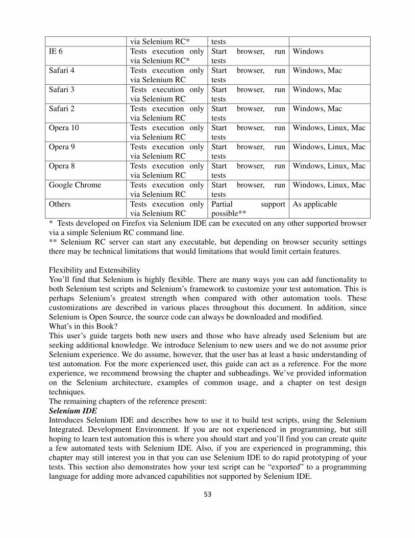
Browser Selenium IDE Selenium 1 (RC) Operating Systems
Firefox 3.x Record and playback
tests
Start browser, run
tests
Windows, Linux, Mac
Firefox 3 Record and playback
tests
Start browser, run
tests
Windows, Linux, Mac
Firefox 2 Record and playback
tests
Start browser, run
tests
Windows, Linux, Mac
IE 8 Tests execution only
via Selenium RC*
Start browser, run
tests
Windows
IE 7 Tests execution only Start browser, run Windows
Page 53
53
via Selenium RC* tests
IE 6 Tests execution only
via Selenium RC*
Start browser, run
tests
Windows
Safari 4 Tests execution only
via Selenium RC
Start browser, run
tests
Windows, Mac
Safari 3 Tests execution only
via Selenium RC
Start browser, run
tests
Windows, Mac
Safari 2 Tests execution only
via Selenium RC
Start browser, run
tests
Windows, Mac
Opera 10 Tests execution only
via Selenium RC
Start browser, run
tests
Windows, Linux, Mac
Opera 9 Tests execution only
via Selenium RC
Start browser, run
tests
Windows, Linux, Mac
Opera 8 Tests execution only
via Selenium RC
Start browser, run
tests
Windows, Linux, Mac
Google Chrome Tests execution only
via Selenium RC
Start browser, run
tests
Windows, Linux, Mac
Others Tests execution only
via Selenium RC
Partial support
possible**
As applicable
* Tests developed on Firefox via Selenium IDE can be executed on any other supported browser
via a simple Selenium RC command line.
** Selenium RC server can start any executable, but depending on browser security settings
there may be technical limitations that would limitations that would limit certain features.
Flexibility and Extensibility
You’ll find that Selenium is highly flexible. There are many ways you can add functionality to
both Selenium test scripts and Selenium’s framework to customize your test automation. This is
perhaps Selenium’s greatest strength when compared with other automation tools. These
customizations are described in various places throughout this document. In addition, since
Selenium is Open Source, the source code can always be downloaded and modified.
What’s in this Book?
This user’s guide targets both new users and those who have already used Selenium but are
seeking additional knowledge. We introduce Selenium to new users and we do not assume prior
Selenium experience. We do assume, however, that the user has at least a basic understanding of
test automation. For the more experienced user, this guide can act as a reference. For the more
experience, we recommend browsing the chapter and subheadings. We’ve provided information
on the Selenium architecture, examples of common usage, and a chapter on test design
techniques.
The remaining chapters of the reference present:
Selenium IDE Introduces Selenium IDE and describes how to use it to build test scripts, using the Selenium
Integrated. Development Environment. If you are not experienced in programming, but still
hoping to learn test automation this is where you should start and you’ll find you can create quite
a few automated tests with Selenium IDE. Also, if you are experienced in programming, this
chapter may still interest you in that you can use Selenium IDE to do rapid prototyping of your
tests. This section also demonstrates how your test script can be “exported” to a programming
language for adding more advanced capabilities not supported by Selenium IDE.
Page 54
54
Selenium 2 Explains how to develop an automated test program using Selenium 2.
Selenium 1
Explains how to develop an automated test program using the selenium RC API. Many examples
are presented in both programming languages and scripting languages. Also, the installation and
setup of Selenium RC is covered here. The various modes, or configurations, that Selenium RC
supports are described, along with their trade-offs and limitation. An architecture diagram is
provided to help illustrate these points. Solutions to common problems frequently difficult for
new Sel-R users are described here, for instance, handling Security Certificates, https requests,
pop-ups, and the opening of new windows.
Test Design Considerations This chapter presents programming techniques for use with Selenium-WebDriver and Selenium
RC. We also demonstrate techniques commonly asked about in the user forum such as how to
design setup and teardown functions, how to implement data-driven tests (tests where one can
vary the data between test passes) and other methods of programming common test automation
tasks.
Selenium_Grid This chapter is not yet developed.
User extensions Describes ways that Selenium can be modified, extended and customized.
The Documentation Tem-Authors Past and Present
In alphabetical order, the following people have made significant contributions to the authoring
of this user’s guide, its publishing infrastructure, or both. We are very grateful to all of them.
• Dave Hunt
• Luke Inman-Semerau
• Mary Ann May-Pumphrey
• Noah Sussman
• Paul Grandjean
• Peter Newhook
• Santiago Suarez-Ordonez
• Simon Stewart
• Tarun Kumar
Acknowledgements A special thanks goes to Patrick Light body. As an administration of the Selenium HQ website,
major contributor to Selenium RC, has support was invaluable when writing the first release of
the user’s guide. Patrick helped us understand our audience. He also set us up with everything we
needed on the seleniumhq.org website for publishing the documents. Also a thanks goes to
Andras Hatvani for his advice on publishing solutions, and to Amit Kumar for participating in
our discussions and for assisting with reviewing the document.
And of course, we must recognize the Selenium Developers. They have truly designed an
amazing tool. Without the vision of the original designers, and the continued efforts of the
Page 55
55
current developers, we would not have such a great tool to pass on to you.
SCRIPTS FOR WEB TESTING 1. web_browser_invoke (broser,site);
//invokes the browser and opens a specified site. browser The name of browser (IE or
NETSCAPE). Site The address of the site.
2. web_cursor_to_image (image, x, y);
// moves the cursor to an image on a page, image. The logical name of the image, x,y The x-and
y-coordinates of the mouse pointer when moved to an image
3. web_cursor_to_label (label x,y);
// moves the cursor to a label on a page, label The name of the label. x,y The x-and y-coordinats
of the mouse pointer when moved to a label.
4. web_cursor_to_link (link, x,y);
// moves the cursor to a link on a page, link The name of the link, x,y The x-and y-coordinates of
the mouse pointer when moved to a link.
5. web_cursor_to_obj (object,x,y);
// moves the cursor to an object on a page, object The name of the object. x,y The x-and y-
coordinates of the mouse pointer when moved to an object.
6. web_event (object,event_name [,x ,y]);
// uns an event on a specified object. object The logical name of the recorded object. event_name
The name of an event handler. x,y The x-and y-coordinates of the mouse pointer when moved to
an object
7. web_file_browse ( object );
// clicks a browse button. object A file-type object.
8. web_file_set (object, value);
// sets the text value in a file-type object. object A file-type object. Value A text string.
9. web_find_text (frame, text_to_find, result_array [, text_before, text_after, index, show]);
// returns the location of text within a frame
10. web_frame_get_text (frame, out_text[,text_before, text_after,index]);
// retrives the text content of a frame.
11. web_frame_get_text_count (frame, regex_text_to_find, count);
//returns the number of occurrences of a regular expression in a frame.
12. web_frame_text_exists ( frame, text_to_find [,text_before,text_after]);
// returns a text value if it is found in a frame.
13. web_get_run_event_mode ( out_mode);
// returns the current run mode out_mode The run mode in use. If the mode is FALSE, the default
parameter, the test runs by mouse operations. If TRUE, is specified, the test runs by events.
14. web_get_timeout ( out_timeout );
// returns the maximu time that WinRunner waits for response from the web.out_timeout The
maximum interval in seconds
15.web_image_click ( image,x,y );
// clicks a hypergraphic link or animage, image The logical name of the image. x,y The x- and y-
coordinates of the mouse pointer when clicked on a hypergraphic link or an image.
16.web_lebel_click (label );
// clicks the specified label, label The name of the label.
17.web_link_click ( link );
// clicks a hypertext link. link The name of link.
18.web_link_valid ( name, valid );
Page 56
56
// checks whether a URL name of a link is valid (not broken). name The logical name of a link.
valid The status of the link may be valid (TRUE) or invalid (FALSE)
19. web_obj_click ( object,x,y );
object The logical name of an object.
x,y The x-and y-coordinates of the mouse pointer when clicked on an object.
20. seb_obj_get_child_item (object, table_row, table_column, object_type, index, out_object);
// returns the description of the children in an object
21. function return the count of the children in an object.
web_obj_get_child_item_count (object, table_row, table_column, object_type, object_count );
22. returns the value of an object property.
web_obj_get_info ( object, property_name, property_value );
23. returns a text string from a object.
web_obj_get_text (object, table_row, table_column, out_text [, text_before, text_after, index]);
24.returns the number of occurrences of a regular expression in an object.
Web_obj_get_text_count ( object, table_row, table_column, regre_to_find, count);
25. returns a text value if it is found in an object.
Web_obj_text_exists ( objects, table_row, table_column, text_to_find [,text_efore,text_after]);
26. web_restore_event_default ( );
// resets all events to their default settings.
27. web_set_event (class, event_name, event_type, event_status );
// sets the event status.
28. web_set_run_event_mode ( mode );
//sets the event run mode.
29. web_set_timeout ( timeout );
//.sets the maximum time WinRunner waits for a response from the web.
30. web_set_tooltip_color (fg_color, bg_color);
// sets the colors of the WebTEst Tool Tip.
31. web_sync (timeout);
// waits for the navigation of a frame to be completed.
32. web_url_valid (URL, valid );
// check whether a URL is valid.
Page 57
57
EXERCISE NO.3
What is BugZilla? BugZilla is bug tracking system (also called as issue tracking system).
Bug tracking systems allow individual or group of developers effectively to keep track of
outstanding problems with their product. Bugzilla was originally in a programming language
called TCL, to replace a rudimentary but-tracking database used internally by Netscape
Communications. Terry later ported Bugzilla to Perl from TCL, and in Perl it remains to this day,
Most commercial defect-tracking software vendors at the time charged enormous licensing fees,
and Bugzilla quickly became a favorite of the open-source crowd (with its genesis in the open-
source browser project, Mozilla). It is now the de-facto standard defect-tracking system against
which all other are measured.
Bugzilla boasts many advanced features. There include:
• Powerful searching
• User-configurable email notifications of bug changes
• Full change history
• Inter-bug dependency tracking and graphing
• Excellent attachment management
• Integrated, product-based, granular security schema
• Fully security-audited, and runs under Perl’s taint mode
• A robust, stable RDBMS back-end
• Web, XML, email and console interfaces
• Completely customizable and/or localizable web user interface
• Extensive configurability
• Smooth upgrade pathway between versions.
Why Should We Use Bugzilla? For many years, defect-tracking software has remained principally the domain of large software
development houses. Even then, most shops never bothered with bug-tracking software, and
instead simply relied on shared lists and email to monitor the status of defect. This procedure is
error-prone and tends to cause those bugs judged least significant by developers to be dropped or
ignored.
These days, many companies are finding that integrated defect_tracking systems reduce
downtime, increase productivity, and raise customer satisfaction with their systems. Along with
full disclosure, an open bug-tracker allows manufacturers to keep in touch with their clients and
resellers, to communicate about problems effectively throughout the data management chain.
Many corporations have also discovered that defect-tracking helps reduce costs by providing IT
support accountability, telephone support knowledge bases, and a common, well-understood
system for accounting for unusual system or software issues.
But why should you use Bugzilla?
Bugzilla is very adaptable to various situations. Known uses currently include IT support queues,
Systems Administration deployment management, chip design and development problem
tracking (both pre-and-post fabrication), and software and hardware bug tracking for luminaries
such as Redhat, NASA, Linux_Mandrake, and VA Systems. Combined with systems such as
CVS, Bonsai, or Perforce SCM, Bugzilla provides a powerful, easy-to-use solution to
Page 58
58
configuration management and replication problems.
Bugzilla can dramatically increase the productivity and accountability of individual employees
by providing a documented workflow and positive feedback for good performance. How many
times do you wake up in the morning, remembering that you were supposed to do something
today, but you just can’t quite remember? Put it in Bugzilla, and you have a record of it from
which you can extrapolate milestones, predict product versions for integration, and follow the
discussion trail that led to critical decisions.
Ultimately, Bugzilla puts the power in your hands to improve your value to your employer or
business while providing a usable framework for your natural attention to detail and knowledge
store to flourish.
How do I use Bugzilla? This section contains information for end-users of Bugzilla. There is a Bugzilla test installation,
called Landfill, which you are welcome to play with (if it’s up.) However, it does not necessarily
have all Bugzilla features enabled, and often runs cutting-edge versions of Bugzilla for testing,
so some things may work slightly differently than mentioned here.
1. Create a Begzilla Account
If you want to use Bugzilla, frist you need to create an account. Consult with the adminsitrator
responsible for your installation of Bugzilla for the URL you should use to access it. If you’re
test-driving Bugzilla.
1. Click the “Open a new Bugzilla account” link, enter your email address and, optionally, your
name in the spaces provided, then “ Create Account”.
2. Within moments, you should receive an email to the address you provided above, which
contains your login name (generally the same as the email address), and a password you can
use to access your account. This password is randomly generated, and can be changed to
something more memorable.
3. Click the “Log In” link in the yellow area at the bottom of the page in your browser, enter
your email address and password into the spaces provided, and click ”Login”.
You are now logged in. Bugzilla uses cookies for authentication so, unless your IP address
changes, you should not have to log in again.
2. Anatomy of aBug The core of Bugzilla is the screen which displays a particular bug. It’s a good place to explain
some Bugzilla concepts. Bug 1 on Landfill is a good example. Note that the labels for most fields
are hyperlinks; clicking them will take you to context-sensitive help on that particular field.
Fields marked * may not be present on every installation of Bugzilla.
1. Product and component: Bugs are divided up by product and component, with a product
having one or more components in it. For example, bugzilla.mozilla. org’s “Bugzilla”.
Product is composed of several Components:
Adminsitration: Administration of a Bugzilla installation.
Bugzilla-General: Anything that doesn’t fit in the other components, or spans multiple
components.
Creating/changing Bugs: Creating, changing, and viewing bugs.
Documentation: The Bugzilla documentation, including the Bugzilla Guide.
Email: Anything to do with email sent by Bugzilla.
Page 59
59
Installation: The installation process of Bugzilla.
Query/Buglist: Anything to do with searching for bugs and viewing the buglists.
Reporting/charting: Getting reports from Bugzilla.
User Accounts: Anything about managing a user account from the user’s perspective.
Saved queries, creating account, changing passwords, logging in, etc.
User interface: General issues having to do with the user interface cosmetics(not functionality)
including cosmetic issues, HTML templates, etc.
2. Status and Resolution: These define exactly what state the bug is in- from not even being
confirmed as a bug, through to being fixed and the fix confirmed by Quality Assurance.
The different possible values for status and Resolution on your installation should be
documented in the context-sensitive help for those items.
3.Assigned To: The person responsible for fixing the bug.
4.*URL: A URL associated with the bug, if any.
5. Summary: A one –sentence summary of the problem.
6. *Status Whiteboard: (a.k.a whiteboard) A free –from text area for adding short notes and tags
to a bug.
7.*Keywords: The administrator can define keywords which you can use to tag and
categorise bugs-e.g. The mozilla project has keywords like crash and regression.
8.Platform and OS: These indicate the computing environment where the bug was found.
9.Version: The “version” field is usually used for versions of a product which have been
released, and is set to indicate which versions of a component have the particular problem
the bug report is about.
10. Priority: The bug assignee uses this field to prioritise his or her bugs. It’s a good idea not
to change this on other people’s bugs.
11. Severity: This indicates how severe the problem is- from blocker(“application unusable”)
to trivial(“minor cosmetic issue”). You can also use this field to indicate whether a bug is
an enhancement request.
12. *Target: (a.k.a Target Milestone) A future version by which the bug is to be fixed.e.g.
The Bugzilla project’s milestones for future Bugzilla version are 2.18,2.20, 3.0,etc.
Milestones are not restricted to numbers, thought-you can use any text strings, such as
dates.
13. Reporter: The person who field the bug.
14. CC list: A list of people who get mail when the bug changes.
15. Attachments: you can attach files(e.g. test cases or patches) to bugs. If there are any
attachments, they are listed in this section.
Page 60
60
16. *Dependencies: If this bug cannot be fixed unless other bugs are fixed (depends on), or
this bug stops other bugs being fixed (blocks), their number are recorded here.
17. *Votes: whether this bug has any votes.
18. Additional comments: you can add your two cents to the bug discussion here, if you have
something worthwhile to say.
3. Searching for bugs
The Bugzilla search page is the interface where you can find any bug report, comment, or
patch currently in the Bugzilla system.
The search page has controls for selecting different possible values for all of the fields in a bug,
as described above. Once you’ve defined a search, you can either run it, or save it as a
Remembered Query, which can optionally appear in the footer of your pages.
Highly advanced querying is done using Boolean Charts.
4. Bug Lists
If you run a search, a list of matching bugs will be returned. The default search is to return all
open bugs on the system-don’t try running this search on a Bugzilla installation with a lot of
bugs!
The format of the list is configurable. For example, it can be sorted by clicking the column
headings. Other useful features can be accessed using the links at the bottom of the list:
Long Format: This gives you a large page with a non-editable summary of the fields of each
bug.
Change Columns: change the bug attributes which appear in the list.
Change several bugs at once: If your account is sufficiently empowered, you can make the
same change to all the bugs in the list-for example, changing their owner.
Send mails to bug owners: Sends mail to the owners of all bugs on the list.
Edit this query: If you didn’t get exactly the results you were looking for, you can return to the
Query page through this link and make small revisions to the query you just made so you get
more accurate results.
5. Filling Bugs Years of bug writing experience has been distilled for your reading pleasure into the Bug writing
Guidelines. While some of the advise is Mozilla-specific, the basic principles of reporting
Reproducible, Specific bugs, isolating the Product you are using, the Version of the Product, the
Component which failed, the Hardware Platform, and Operating system you were using at the
time of the failure go a long way toward ensuring accurate, responsible fixes for the bug that bit
you.
The procedure for filing a test bug is as follows:
1. Go to Landfill in your browser and click Enter a new bug report.
2. Select a product-any one will do.
3. Fill in the fields. Bugzilla should have made reasonable guesses, based upon your
Page 61
61
browser, for the “Platform” and “OS” drop-down boxes. If they are wrong, change
them.
4. Select ”Commit” and send in your bug report.
Page 62
62
EXERCISE NO. 4
TEST DIRECTOR
Introduction Test Director, the industry’s first global test management solution, helps organizations deploy
high-quality applications more quickly and effectively.
Its four modules Requirements, Test Plan, Test Lab, and Defects are seamlessly integrated,
allowing for a smooth information flow between various testing stages. The completely web-
enabled Test Director supports high levels of communication and collaboration among distribute
testing teams, driving a more effective, efficient global application-testing process.
Contents:
• Features
• Benefits
Features in Test Director 7.5?
• Web-based site Administrator
• The site Administrator includes tabs for managing projects, adding users and defining
user properties, monitoring connected users, monitoring licenses and monitoring
Test Director server information.
• Domain Management
• Test Director projects are grouped by domain. A domain contains a group of related
Test Director projects, and assists you in organizing and managing a large number of
projects.
• Enhanced Reports and Graphs
• Additional standard report types and graphs have been added, and the user interface is
richer in functionality. The new format enables you to customize more features.
• Version control
• Version control enables you to keep track of the changes you make to the testing
information in your Test Director project. You can use version control database for,
tracking manual, WinRunner and Quick Test Professional tests in the test plan tree and
test grid.
• Collaboration Module
• The Collaboration module, available to existing customers as an optional upgrade, allow
you to initiate an online chat session with another Test director user. While in a chat
session, users can share applications and make changes.
• Features in TestDirector8.0?
• TestDirector Advanced Reports Add-in
• With the new Advanced Reports Add-in TestDirector users are able to maximize a the
value of their testing project information by generating customizable status and progress
reports. The Advanced Reports Add-in offers the flexibility to create custom report
configurations and layouts, unlimited ways to aggregate and compare data and ability to
generate cross- project analysis reports.
• Automatic Traceability Notification
• The new traceability automatically traces changes to the process entities such as
requirements or tests, and notifies the user via flag or e-mail. For example, when the
requirement changes, the associated test is flagged and tester is notified that the test may
need to be reviewed to reflect requirement changes.
Page 63
63
Coverage Analysis View in Requirements Module
• The graphical display enables you to analyze the requirements according to test coverage
status and view associated tests-grouped according to test status.
• Hierarchical Test Sets
• Hierarchical test sets provide the ability to better organize your test run process by
grouping test sets into folders.
• Workflow for all Test Director Modules
• The addition of the script editor to all modules enables organizations to customize
TestDirector to follow and enforce any methodology and best practices.
• Improved Customization
• With a greater number of available user fields, ability to add memo fields and create
input
masks users can customize their TestDirector projects to capture any data required by
their testing process. New rich edit option add formatting options to all memo
fields.
TestDirector Features&Benefits
• Supports the entire testing process
• TestDirector incorporates all aspects of the testing process requirements management,
planning, scheduling, running tests, issue management and project status analysis into a
single browser-based application.
• Leverages innovative web technology
• Testers, developers and business analysts can participate in and contribute to the testing
process by working seamlessly across geographic and organizational boundaries.
• Uses industry –standard repositories
• TestDirector integrates easily with industry-standard databases such as SQL, Oracle,
Access and sybase.
• Links test plans to requirements
• TestDirector connects requirements directly to test cases, ensuring that functional
requirements have been covered by the test plan
• Integrates with Microsoft office
• TestDirector can import requirements and test plans from Microsoft office, preserving
your investment and accelerating your testing process.
• Manages manual and automated tests
• TestDirector stores and runs both manual and automated tests, and can helps jumpstart
a user’s automation project by converting manual tests to automated test scripts.
• Accelerates testing cycles
• TestDircector’s TestLab manager accelerates the test execution cycles by scheduling and
running tests automatically-unattended, even overnight. The results are reported into
TestDirector’s central repository, creating an accurate audit trail for analysis.
• Supports test runs across boundaries
• TestDirector allows testers to run testers to run tests on their local machines and then
report the results to the repository that resides on a remote server.
Page 64
64
• Integrates with internal and third-party tools
• Documented COM API allows TestDirector to be integrated both with internal tools
(e.g.,
WinRunner and LoadRunner) and external third-party lifecycle applications.
Enables structured information sharing
• Test Director controls the information flow in a structured and organized manner. It
define the role of each tester in the process and sets the appropriate permissions to ensure
information integrity.
• Provides Analysis and Decision support Tools
• Test Director’s integrated graphs and reports help analyze application readiness at any
point in the testing process. Using information about requirements coverage, planning
progress, run schedules or defect statistics, managers are able to make informed
decisions
on whether the application is ready to go live.
• Provides easy defect reporting
• Test Director offers a defect tracking process that can identify similar defects in a
database.
• Generates customizable reports
• Test Director features a variety of customizable graphs and reports that provide a
snapshot of the process a t any time during testing. You can save your favorite views to
have instant access to relevant project information.
• Supports decision-making through analysis
• Test Director helps you make informed decisions about application readiness through
dozens of reports and analysis features.
• Provides Anytime , Anywhere Access to testing Assets
• Using Test Director’s Web interface, testers, developers and business analysts can
participate in and contribute to the testing process by collaborating across geographic and
organizational boundaries.
• Provides Traceability Throughout the Testing Process
• Test director links requirements to test cases, and test cases to issues, to ensure
traceability throughout the testing cycle. When requirement changes or the defect is
fixed, the tester is notified of the change.
• Integrates with Third-party Applications.
• Whether an individual uses an industry standard configuration management solution,
Microsoft Office or a homegrown defect management tool, any application can be
integrated into Test Director. Though the API, Test Director preserves the users’
investment in their existing solutions and enables them to create end-to-end lifecycle –
management solution.
• Manages Manual and Automated Tests
• Test Director stores and runs both manual and automated tests, and can help jumpstart a
user’s automation project by converting manual tests to automated test scripts.
• Accelerates Testing Cycles
Page 65
65
• Test Director’s Test Lab manager accelerates the test execution cycles by scheduling and
running tests automatically-unattended, even overnight. The results are reported into
Test Director’s central repository, creating an accurate audit trail for analysis.
Supports test runs across boundaries
• Test Director allows testers to run on their local machines and then report the results
to the repository that resides on a remote server.
• Integrates with internal and third-party tools
• Documented COM API allows Test Director to be integrated both with internal tools(e.g.,
WinRunner and LoadRunner) and external third-party lifecycle applications.
• Enables structured information sharing
• Test Director controls the information flow in structured and organized manner. It
defines the role of each tester in the process and sets the appropriate permission to ensure
information integrity.
• Provides Analysis and Decision support tools
• Test Director’s integrated graphs and reports help analyze application readiness at any
point in the testing process. Using information about requirements coverage, planning
progress, run schedules or defect statistics, managers are able to make informed decisions
on whether the application is ready to go live .
• Provides easy defect reporting
• Test Director offers a defect tracking process that can identify similar defects in a
database.
• Generates customizable reports
• Test Director features a variety of customizable graphs and reports that provide snapshot
of the process at any time during testing. You can save your favorite views to have
instant access to relevant project information.
• Support decision-making through analysis
• Test Director helps you make informed decision about application readiness through
dozens of reports and analysis features.
• Provides Anytime, Anywhere Access to Testing Assets
• Using Test Director’s Web interface, testers, developers and business analysts can
participate in and contribute to the testing process by collaborating across geographic and
organizational boundaries.
• Provides Traceability Throughout the Testing Process
• Test Director links requirements to test cases, and test cases to issues, to ensure
traceability throughout the testing cycle. When requirement changes or the defect is
fixed, the tester is notified of the change.
• Integrates with Third-party Applications
Page 66
66
• Whether an individual uses an industry standard configuration management solution,
Microsoft Office or a homegrown defect management tool, any application can be
integrated into Test Director. Through the open API, Test Director preserves the users’
investment in their existing solutions and enables them to create an end-to end lifecycle-
management solution.
• Manages manual and Automated Tests
• Test Director stores and runs both manual and automated tests, and can help jumpstart a
user’s automation project by converting manual tests to automated test scripts.
• Accelerates Testing Cycles
• Test Director’s Test Lab manager accelerates the test execution cycles by scheduling and
running tests automatically unattended, even overnight. The results are reported into Test
Director’s central repository, creating an accurate audit trail for analysis.
• Facilitates Consistent and Repetitive Testing Process.
• By providing a central repository for all testing assets, Test Director facilitates the
adoption of a more consistent testing process, which can be repeated throughout the
application lifecycle or shared across multiple applications or lines of business ( LOB).
• Testing process
• Test management is a method for organizing application test assets-such as test
requirements, test plans, documentation, test scripts or test results-to enable easy
accessibility and reusability. Its aim is to deliver quality applications in less time.
• The test management, process is the main Principle behind mercury Inter active’s Test
Director. It is the first tool to capture the entire test management process-requirements
management, test planning, test execution and defect management-in one powerful,
scalable and flexible solution.
• Managing Requirements
• Requirements are what the users or the system needs. Requirement management,
however, is a structured process for gathering, organizing, documenting and managing
the requirements throughout the project lifecycle. Too often, requirements are neglected
during the testing effort, leading to a chaotic process of fixing what you can and
accepting that certain functionally will not be verified. In many organizations,
requirements are maintained in Excel or Word documents, which makes it difficult for
team members to share information and to make frequent revisions and changes.
• Test Director supports requirements-based testing and provides the testing team with a
clear, concise and functional blue print for developing test cases. Requirements are linked
to tests- that is, when the test passes or fails, this information is reflected in the
requirement records. You can also generate a test based on a functional requirement and
instantly create a link between the requirement, the relevant test and any defects that are
uncovered during the test run.
• Test Planning
• Based on the requirements, testers can start building the test plan and designing the actual
Page 67
67
tests. Today, organizations no longer wait to start testing at the end of the development
stage, before implementation. Instead, testing and development begin simultaneously.
This parallel approach to test planning and application design, ensure that testers build a
complete set of tests that cover every function the system is designed to perform.
• Test Director provides a centralized approach to test design, which is invaluable for
gathering input from different members of the testing team and providing a central
reference point for all of your future testing efforts. In the plan module, you can design
tests-manual and automated- document the testing procedures and create quick graphs
and reports to help measure the progress of the test planning effort.
• Running Tests
• After you have addressed the test design and development issues and built the test plan,
your testing team is ready to start running tests.
• Test Director can help configure the test environment and determine which tests will run
on which machines. Most applications must be tested on different operating systems,
different browser versions or other configurations. In Test Director’s Test Lab, testers can
set up groups of machines to most efficiently use their lab resources.
• Test Director can also schedule automated tests, which saves time by running
multiple tests simultaneously across multiple machines on the network. Tests with
Test Director can be scheduled to run unattended, overnight or when the system is in least
Demand for other tasks. For both manual and automated tests, Test Director can keep a
Complete history of all test runs. By using this audit trail, testers can easily trace changes
to tests and test runs.
• Managing Defects
• The keys to creating a good defect management process are setting up the defect work
flow and assigning permission rules. With Test Director, you can clearly define how the
lifecycle of a defect should progress, who has the authority to open a new defect, who can
change a defect’s status to “fixed” and under which conditions the defect can be officially
closed. Test Director will also help you maintain a complete history and audit trail
throughout the defect lifecycle.
• Managers often decide whether the application is ready to go live based on defect
analysis. By analyzing the defect statistics in Test Director, you can take a snap short of
the application under test and see exactly how many defect you currently have, their
status, severity, priority, age etc. Because Test Director is completely Web-based,
different members of the team can have instant access to defect information, greatly
improving communication in your organization and ensuring everyone is up to date on
the status of the application.
Page 68
68
EXERCISE NO.5 What is Test Link?
In an ideal world, testing would be a pretty straightforward process. A test team takes the product
requirements, writes a test specification document, reviews the tests, and then runs them all for
each version of the product. The team is composed of full-time staff, and everyone knows
exactly what is expected of them.
In practice few organizations have that luxury. There is not time to run all the tests on every
product version- especially on fix-releases that need to be rolled out quickly. Requirements are
constantly changing, and the tests have to be changed in step. Test staff come and go. There are
misunderstandings over who was supposed to run which tests, so some get missed. Management
suddenly wants a status update at seven in the evening.
In these situations you need the support of a test management tool, such as Test Link.
The purpose of Test Link is to answer question such as:
- For which requirements do we still need to write or update test cases?
- Which tests do you want me to run for this version?
- How much progress have we made on testing this release?
- Which test cases are currently failing, and what are the errors?
- On which version was this group of test cases last run, and it time we ran them again?
- And ultimately: is this version of the product fit for release?
Test Link helps you to keep the test process under control. It forms a repository for requirements
and test cases, and relates these to builds, platforms and staff. You allocate tests to staff who
carry them out and record the results. A wide variety of reports provide information on what has
been done and what still needs to be done.
Test Link 1.9 Documentation
• User Manual
Test Link 1.8 Documentation
• User manual
• Installation & configuration manual
• Developers Guide-useful information about process, structure, standards and technical
solutions within TL.
• Code-generated documentation for library and API.
• Enhanced configuration of HTML editor by Julian
• French presentation about Test Link by B.Biache from ITESOFT.
Test Link 1.7 Documentation
• User manual
• Installation & Configuration manual
• How to setup Bug tracking system in TL 1.6.
• Unofficial work-flow presentation.
Use can also use sources from CVS: Do you miss some specific information? Could you help to
clarify text? Please send into e-mail to our documentation account. Please, do not expect answer
Page 69
69
(use forum if you are looking for answer).
Older Documentation
• Test Link 1.6 User manual
• Test Link 1.6 Installation & configuration manual
• Test Link 1.6 Developer Environment setup Guide
• Mantis integration
• Test Link 1.5 User manual
• Test Link 1.5 Installation & configuration manual
• Test Link 1.0.4 User and Installation manual
• What software testing types can be considered?
Black box Testing - This type of testing doesn’t require any knowledge of the internal design or
coding. These Tests are based on the requirements and functionality.
White box testing – This kind of testing is based on the knowledge of internal logic of a
particular application code. The testing is done based on the coverage of code statements, paths,
conditions.
Unit testing - The ‘micro’ scale of testing; this is mostly used to test the particular functions or
code modules. This is typically done by the programmer and not by testers; it requires detailed
knowledge of the internal program design and code. It cannot be done easily unless the
application has a well-designed architecture with tight code; this type may require developing
test driver modules or test harnesses.
Sanity testing or smoke testing – This type of testing is done initially to determine if a new
software version is performing well enough to accept it for a major testing effort. For example, if
the new software is crashing the systems in every 5 minutes or corrupting databases, the software
may not be in a ‘sound’ condition to proceed for further testing in its current state.
Function testing – The a commonly used black-box testing geared a check the functional
requirements of an application; this type of testing should be done by testers.
Integration testing – This testing is combining the ‘parts’ of an application to determine if they
function together correctly. The ‘part’ can be code modules, individual applications, client and
server applications on a network, etc. This type of testing is especially relevant to the
client/server and distributed systems.
Incremental integration testing- This is continuous testing of an application when a new
functionality is added the existing ones; it checks the application functionality by verifying
whether it works separately before all parts of the program are completed, in this type it will be
Checked whether to introduce test drivers or not; this is done by programmers or by testers.
Regression testing- This is testing the whole application again after the fixes or the modification
are done on the software. This is mostly done at the end of the software development life cycle.
Mostly Automated testing tools are used for these type of testing.
System testing- This is a type of black-box type testing that is based on overall requirements
specifications; covers all combined parts of a system.
End-to-end testing – This is similar to system testing; this involves testing of a complete
application environment such as interacting with a database, using network communications, or
Page 70
70
interacting with other hardware, applications and so on.
UAT(User Acceptance Testing) – This type of testing comes on the final stage and mostly done
on the specifications of the end-user or client.
Usability testing- This testing is done to check the ‘user-friendliness’ of the application. This
depends on the targeted end –user or customer. User interviews, surveys, video recording of user
sessions, and other techniques can be used. Programmers and testers are usually not appropriate
as usability testers.
Compatibility testing- Testing how well the software performs in a particular hardware,
software, operating system, network etc.
Comparsion testing – This is nothing comparing the software strengths and weakness with
another competing product.
Mutation testing- This is another method for determining if a set of test data or test cases useful,
by purposely introducing various code changes or bugs and retesting with the original test data or
cases to determine whether the ‘bugs’ are detected.