Brake PB-120 146 Warner Electric • 800-234-3369 P-1264-WE • 4/11 Static Torque 5 lb.in. Maximum Speed 10,000 rpm Standard Voltage D.C. 6, 24, 90 ARMATURE VIEW MAGNET VIEW Customer Shall Maintain: 1. Concentricity of brake mounting pilot diameter with armature shaft within .003 T.I.R. 2. Squareness of brake mounting face with armature shaft within .003 T.I.R. Bore Dimensions Armature Bore Dia. .188/.187 .251/.250 (.313/.312)* *(Antibacklash Armatures) Antibacklash Arm. Std.Arm. For Bore sizes see chart below. 45° 1.499/1.497 Pilot Dia. .130/.123 dia. (4) holes equally spaced on 1.312 dia. Mounting holes are within .006 of true position relative to pilot diameter. 1.125 Max. Sq. .109 (Std.) .140 (Anti.) .015 When New .072 (Std.) .072 (Anti.) 12 .375 Dia. #4-40 UNC-3A .187 Max. .062 .500 Anti Arm. .015 Nom. .072 (Std.) .072 (Anti.) Std.Arm. .562 1.234 Max. Dia. .312 .968 Max. .343 .625 All dimensions are nominal unless otherwise noted. Information on inertia and weights begins on page 239. Coil data is on pages 250 and 251.
Transcript
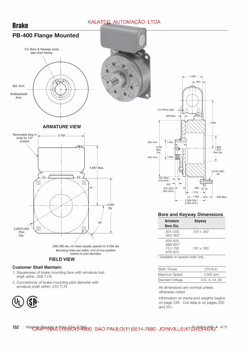
Brake
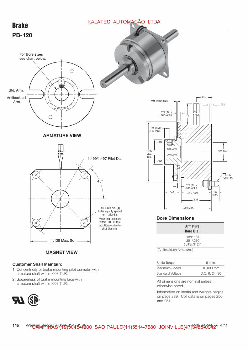
PB-120
146 Warner Electric • 800-234-3369 P-1264-WE • 4/11
Static Torque 5 lb.in.
Maximum Speed 10,000 rpm
Standard Voltage D.C. 6, 24, 90
ARMATURE VIEW
MAGNET VIEW
Customer Shall Maintain:
1. Concentricity of brake mounting pilot diameter witharmature shaft within .003 T.I.R.
2. Squareness of brake mounting face witharmature shaft within .003 T.I.R.
Bore Dimensions
Armature
Bore Dia.
.188/.187
.251/.250(.313/.312)*
*(Antibacklash Armatures)
AntibacklashArm.
Std. Arm.
For Bore sizessee chart below.
45°
1.499/1.497 Pilot Dia.
.130/.123 dia. (4)holes equally spaced
on 1.312 dia.
Mounting holes arewithin .006 of trueposition relative to
149P-1264-WE • 4/11 Warner Electric • 800-234-3369
Brake
PB-170
Drawing I-25753
3
1A-3
2
1B
1A-1
1A-2
1A
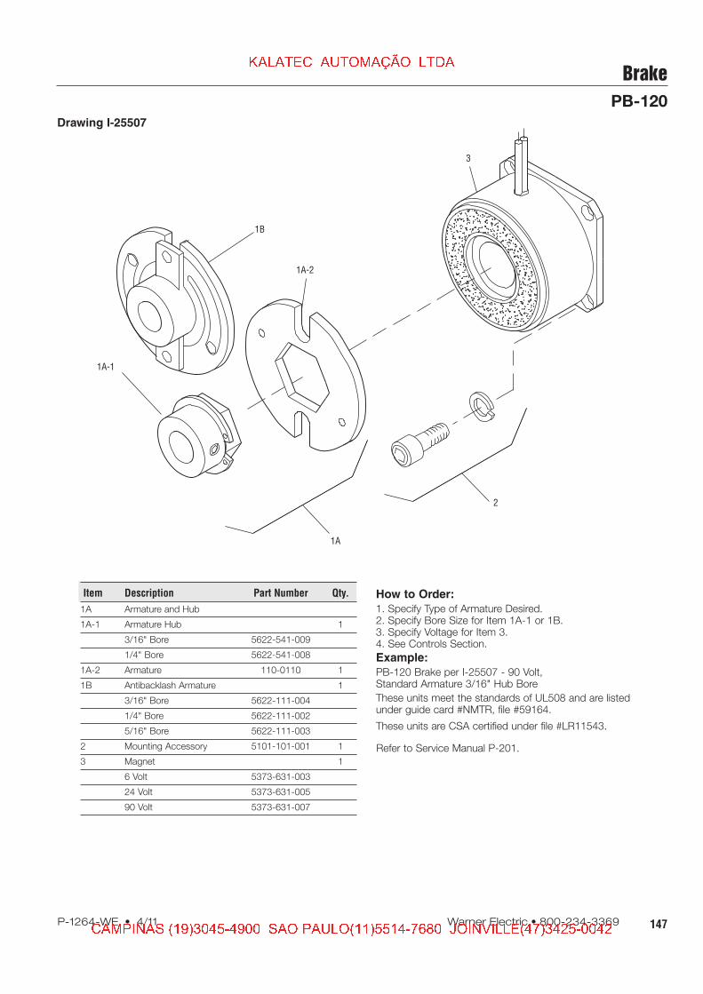
How to Order:
1. Specify Type of Armature Desired.2. Specify Bore Size for Item 1A-1 or 1B.3. Specify Voltage for Item 3.4. See Controls Section.Example:PB-170 Brake per I-25753 - 90 Volt,Antibacklash Armature1/4" Armature Hub Bore
These units meet the standards of UL508 and are listedunder guide card #NMTR2, file #59164.
These units are CSA certified under file #LR11543.
155P-1264-WE • 4/11 Warner Electric • 800-234-3369
Brake
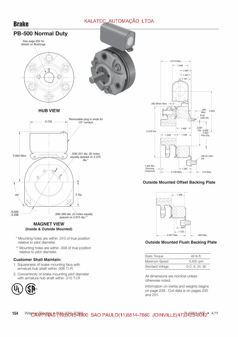
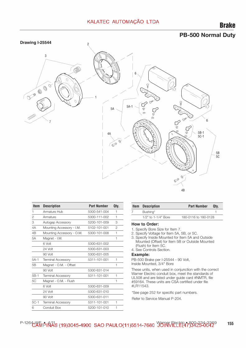
PB-500 Normal Duty
Drawing I-25544
How to Order:
1. Specify Bore Size for Item 7.2. Specify Voltage for Item 5A, 5B, or 5C.3. Specify Inside Mounted for Item 5A and Outside
Mounted (Offset) for Item 5B or Outside Mounted(Flush) for Item 5C.
4. See Controls Section.
Example:
PB-500 Brake per I-25544 - 90 Volt,Inside Mounted, 3/4" Bore
These units, when used in conjunction with the correctWarner Electric conduit box, meet the standards ofUL508 and are listed under guide card #NMTR, file#59164. These units are CSA certified under file#LR11543.
157P-1264-WE • 4/11 Warner Electric • 800-234-3369
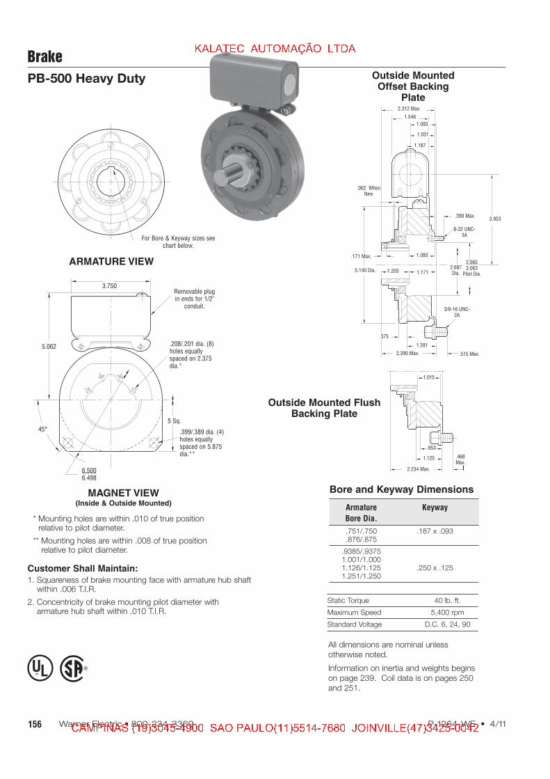
Brake
PB-500 Heavy Duty
Drawing I-25550
How to Order:
1. Specify Bore Size for Item 7.2. Specify Voltage for Item 4A, 4B, or 4C.3. Specify Inside Mounted for Item 4A and Outside
Mounted (Offset) for Item 4B or Outside Mounted (Flush)for Item 4C.
4. See Controls Section.
Example:
PB-500 Brake per I-25550 - 90 Volt,Inside Mounted, 1" Bore
These units, when used in conjunction with the correctWarner Electric conduit box, meet the standards of UL508and are listed under guide card #NMTR, file #59164. Theseunits are CSA certified under file #LR11543.
159P-1264-WE • 4/11 Warner Electric • 800-234-3369
Drawing I-25730
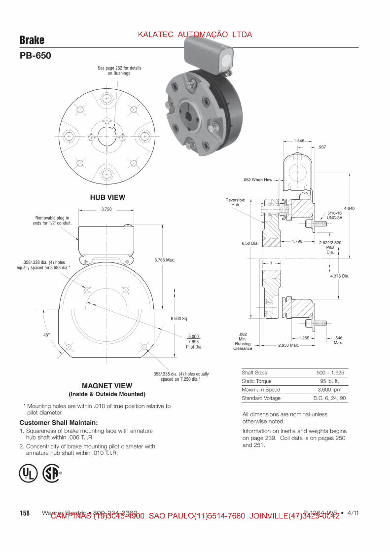
Brake
PB-650
How to Order:
1. Specify Bore Size for Item 2.2. Specify Voltage for Item 5.3. Specify Inside or Outside Mounted for Item 5.4. See Controls Section.
Example:
PB-650 Brake per I-25730 - 90 Volt, 1" Bore
These units, when used in conjunction with the correctWarner Electric conduit box, meet the standards of UL508and are listed under guide card #NMTR, file #59164. Theseunits are CSA certified under file #LR11543.
161P-1264-WE • 4/11 Warner Electric • 800-234-3369
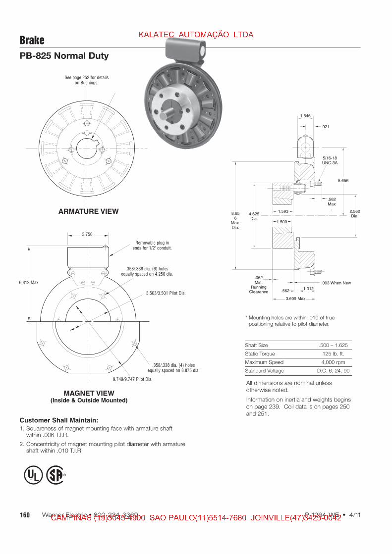
Brake
PB-825 Normal Duty
Drawing I-25566
How to Order:
1. Specify Bore Size for Item 1.2. Specify Inside Mounted for Items 5A and 6A or
Outside Mounted for Items 5B and 6B.3. Specify Voltage for Item 6A or 6B.4. See Controls Section.
Example:
PB-825 Brake per I-25566 -90 Volt, Inside Mounted, 1" Bore
These units, when used in conjunction with the correctWarner Electric conduit box, meet the standards of UL508and are listed under guide card #NMTR, file #59164. Theseunits are CSA certified under file #LR11543.
2
1
3
4
7
6B-1
6B
7
6A-16A
5A5B
Item Description Part Number Qty.
1 Bushing* 1
1/2" to 1-5/8" Bore 180-0131 to 180-0149
2 Armature Hub 540-0394 1
3 Armature 5301-111-018 1
4 Autogap Accessory 5201-101-008 3
5A Mounting Accessory - I.M. 5321-101-001 1
5B Mounting Accessory - O.M. 5321-101-002 1
6A Magnet - Inside Mounted 1
6 Volt 5311-631-002
24 Volt 5311-631-003
90 Volt 5311-631-004
†90 Volt LK Facing 5311-631-011
6A-1 Terminal Accessory 5311-101-001 1
6B Magnet, Outside Mounted 1
6 Volt 5311-631-007
24 Volt 5311-631-009
90 Volt 5311-631-008
†90 Volt LK Facing 5311-631-012
Item Description Part Number Qty.
6B-1 Terminal Accessory 5311-101-001 1
7 Conduit Box 5200-101-011 1
*See page 252 for specific part numbers.
Refer to Service Manual P-208.
†Optional LK facing available. For more information, see
163P-1264-WE • 4/11 Warner Electric • 800-234-3369
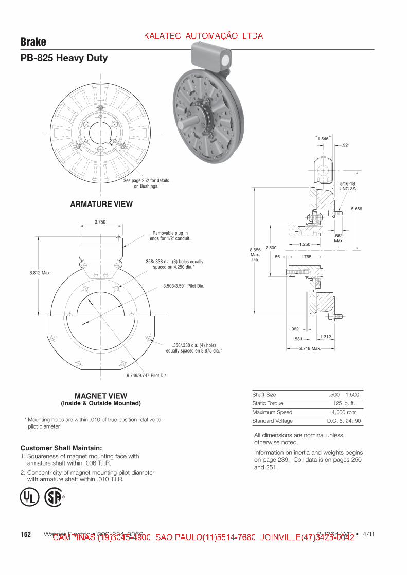
Brake
PB-825 Heavy Duty
Drawing I-25567
How to Order:
1. Specify Bore Size for Item 2.2. Specify Inside Mounted for Items 5A and 6A or
Outside Mounted for Items 5B and 6B.3. Specify Voltage for Item 6A or 6B.4. See Controls Section.
Example:
PB-825 Brake per I-25567 - 90 Volt,1" Bore, Inside Mounted
These units, when used in conjunction with the correctWarner Electric conduit box, meet the standards of UL508and are listed under guide card #NMTR, file #59164. Theseunits are CSA certified under file #LR11543.
1(Shipped
Assembled)
1-5
1-1
1-2
1-4
1-3
3
4
2
6A 6A-1
6B-1
7
7
6B
5B
5A
Item Description Part Number Qty.
1 Armature Assembly 5321-111-001 1
1-1 Armature 5321-111-022 1
1-2 Splined Adapter 104-0008 1
1-3 Autogap Accessory 5321-101-006 1
1-4 Screw 797-0272 3
1-5 Locknut 661-0004 3
2 Bushing* 1
1/2" to 1-1/2" Bore 180-0002 to 180-0018
3 Splined Hub 540-0057 1
4 Retainer Ring 748-0006 1
5A Mounting Accessory - I.M. 5321-101-001 1
5B Mounting Accessory - O.M. 5321-101-002 1
6A Magnet - Inside Mounted 1
6 Volt 5311-631-002
24 Volt 5311-631-003
90 Volt 5311-631-004
†90 Volt LK Facing 5311-631-011
6A-1 Terminal Accessory 5311-101-001 1
6B Magnet - Outside Mounted 1
6 Volt 5311-631-007
24 Volt 5311-631-009
90 Volt 5311-631-008
†90 Volt LK Facing 5311-631-012
Item Description Part Number Qty.
6B-1 Terminal Accessory 5311-101-001 1
7 Conduit Box 5200-101-011 1
*See page 252 for specific part numbers.
Refer to Service Manual P-209.
†Optional LK facing available. For more information, see
165P-1264-WE • 4/11 Warner Electric • 800-234-3369
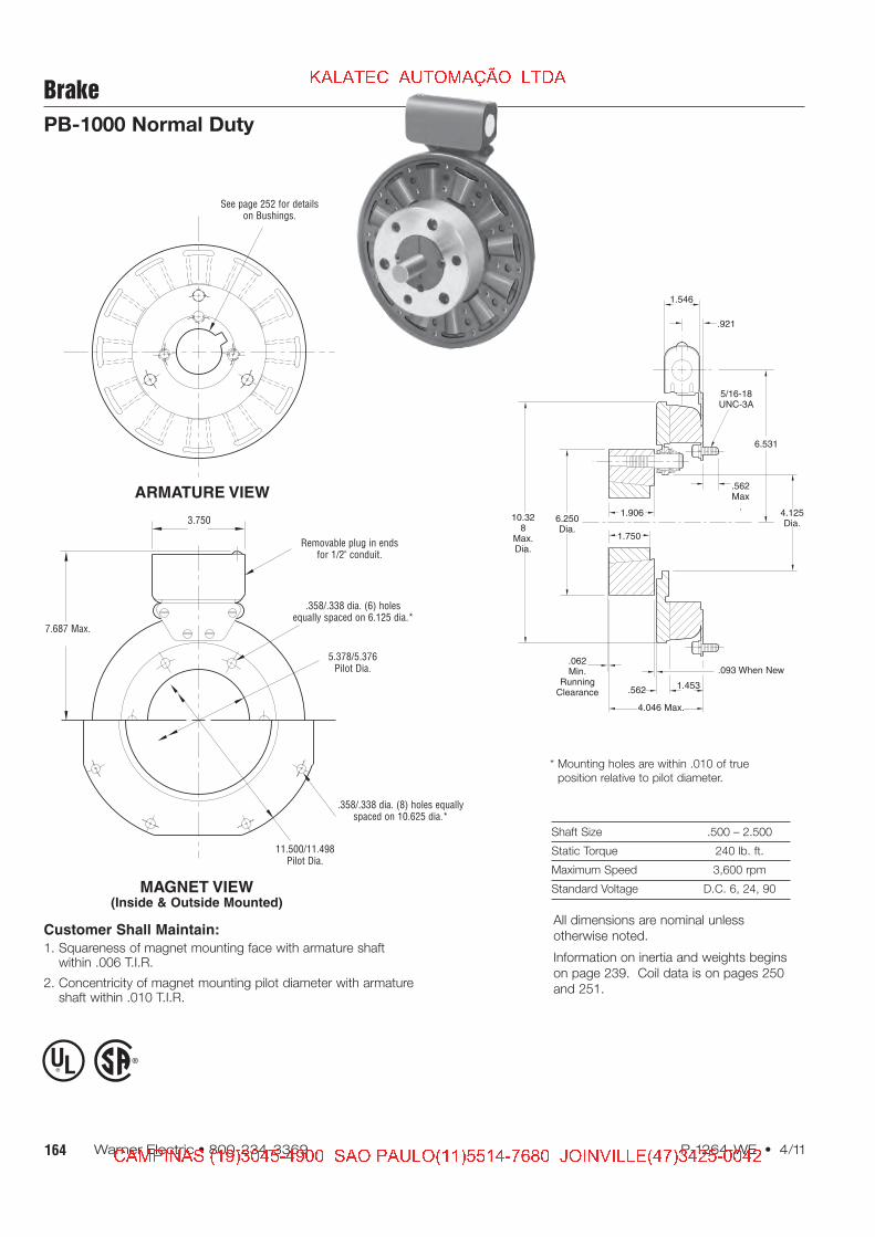
Brake
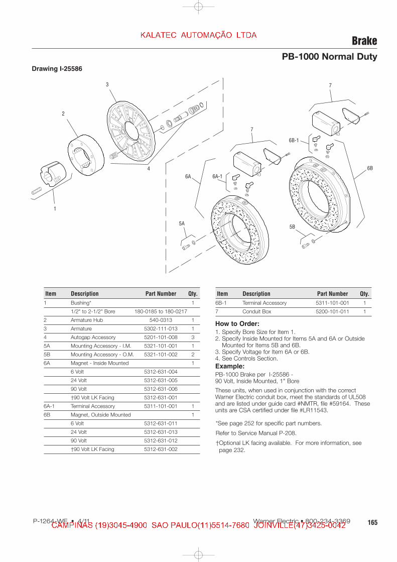
PB-1000 Normal Duty
Drawing I-25586
How to Order:
1. Specify Bore Size for Item 1.2. Specify Inside Mounted for Items 5A and 6A or Outside
Mounted for Items 5B and 6B.3. Specify Voltage for Item 6A or 6B.4. See Controls Section.
Example:
PB-1000 Brake per I-25586 -90 Volt, Inside Mounted, 1" Bore
These units, when used in conjunction with the correctWarner Electric conduit box, meet the standards of UL508and are listed under guide card #NMTR, file #59164. Theseunits are CSA certified under file #LR11543.
2
1
3
4
7
6B-1
6B
7
6A-16A
5A5B
Item Description Part Number Qty.
1 Bushing* 1
1/2" to 2-1/2" Bore 180-0185 to 180-0217
2 Armature Hub 540-0313 1
3 Armature 5302-111-013 1
4 Autogap Accessory 5201-101-008 3
5A Mounting Accessory - I.M. 5321-101-001 1
5B Mounting Accessory - O.M. 5321-101-002 2
6A Magnet - Inside Mounted 1
6 Volt 5312-631-004
24 Volt 5312-631-005
90 Volt 5312-631-006
†90 Volt LK Facing 5312-631-001
6A-1 Terminal Accessory 5311-101-001 1
6B Magnet, Outside Mounted 1
6 Volt 5312-631-011
24 Volt 5312-631-013
90 Volt 5312-631-012
†90 Volt LK Facing 5312-631-002
Item Description Part Number Qty.
6B-1 Terminal Accessory 5311-101-001 1
7 Conduit Box 5200-101-011 1
*See page 252 for specific part numbers.
Refer to Service Manual P-208.
†Optional LK facing available. For more information, see
167P-1264-WE • 4/11 Warner Electric • 800-234-3369
Brake
PB-1000 Heavy Duty
Drawing I-25587
How to Order:
1. Specify Bore Size for Item 2.2. Specify Inside Mounted for Items 5A and 6A or Outside
Mounted for Items 5B and 6B.3. Specify Voltage for Item 6A or 6B.4. See Controls Section.
Example:
PB-1000 Brake per I-25587 - 90 Volt,1-1/2" Bore, Inside Mounted
These units, when used in conjunction with the correctWarner Electric conduit box, meet the standards of UL508and are listed under guide card #NMTR, file #59164. Theseunits are CSA certified under file #LR11543.
Item Description Part Number Qty.
1 Armature Assembly 5322-111-002 1
1-1 Armature 5322-111-036 1
1-2 Splined Adapter 104-0009 1
1-3 Autogap Accessory 5322-101-004 1
1-4 Screw 797-0272 3
1-5 Locknut 661-0004 3
2 Bushing* 1
3/4" to 2-11/16" Bore 180-0026 to 180-0057
3 Splined Hub 540-0062 1
4 Retainer Ring 748-0007 1
5A Mounting Accessory - I.M. 5321-101-001 1
5B Mounting Accessory - O.M. 5321-101-002 2
6A Magnet - Inside Mounted 1
6 Volt 5312-631-004
24 Volt 5312-631-005
90 Volt 5312-631-006
†90 Volt LK Facing 5312-631-001
6A-1 Terminal Accessory 5311-101-001 1
6B Magnet - Outside Mounted 1
6 Volt 5312-631-011
24 Volt 5312-631-013
90 Volt 5312-631-012
†90 Volt LK Facing 5312-631-002
Item Description Part Number Qty.
6B-1 Terminal Accessory 5311-101-001 1
7 Conduit Box 5200-101-011 1
*See page 252 for specific part numbers.
Refer to Service Manual P-209.
†Optional LK facing available. For more information, see
169P-1264-WE • 4/11 Warner Electric • 800-234-3369
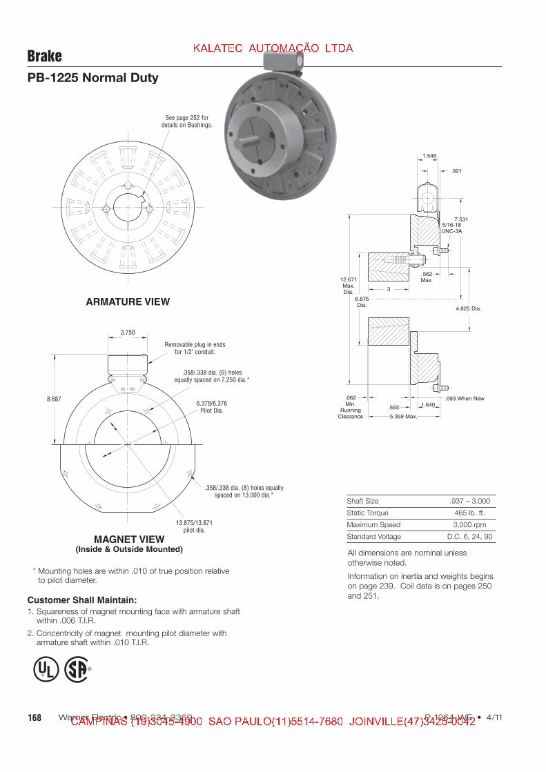
Brake
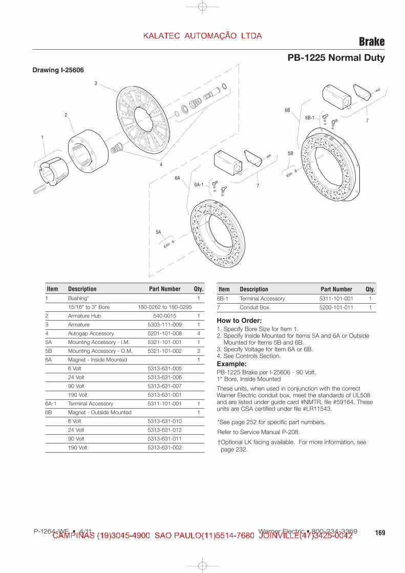
PB-1225 Normal Duty
Drawing I-25606
How to Order:
1. Specify Bore Size for Item 1.2. Specify Inside Mounted for Items 5A and 6A or Outside
Mounted for Items 5B and 6B.3. Specify Voltage for Item 6A or 6B.4. See Controls Section.
Example:
PB-1225 Brake per I-25606 - 90 Volt,1" Bore, Inside Mounted
These units, when used in conjunction with the correctWarner Electric conduit box, meet the standards of UL508and are listed under guide card #NMTR, file #59164. Theseunits are CSA certified under file #LR11543.
1
2
3
4
7
6B
6B-17
5B
6A
6A-1
5A
Item Description Part Number Qty.
1 Bushing* 1
15/16" to 3" Bore 180-0262 to 180-0295
2 Armature Hub 540-0015 1
3 Armature 5303-111-009 1
4 Autogap Accessory 5201-101-008 4
5A Mounting Accessory - I.M. 5321-101-001 1
5B Mounting Accessory - O.M. 5321-101-002 2
6A Magnet - Inside Mounted 1
6 Volt 5313-631-005
24 Volt 5313-631-006
90 Volt 5313-631-007
†90 Volt 5313-631-001
6A-1 Terminal Accessory 5311-101-001 1
6B Magnet - Outside Mounted 1
6 Volt 5313-631-010
24 Volt 5313-631-012
90 Volt 5313-631-011
†90 Volt 5313-631-002
Item Description Part Number Qty.
6B-1 Terminal Accessory 5311-101-001 1
7 Conduit Box 5200-101-011 1
*See page 252 for specific part numbers.
Refer to Service Manual P-208.
†Optional LK facing available. For more information, see
171P-1264-WE • 4/11 Warner Electric • 800-234-3369
Brake
PB-1225 Heavy Duty
How to Order:
1. Specify Bore Size for Item 2.2. Specify Inside Mounted for Items 5A and 6A or Outside
Mounted for Items 5B and 6B.3. Specify Voltage for Item 6A or 6B.4. See Controls Section.
Example:
PB-1225 Clutch per I-25607 -90 Volt, 1-1/2" Bore, Inside Mounted
These units, when used in conjunction with the correct WarnerElectric conduit box, meet the standards of UL508 and arelisted under guide card #NMTR, file #59164. These units areCSA certified under file #LR11543.
1(Shipped
Assembled)
1-5
1-1
1-2
1-4
1-3
3
4
2
6A
5A
7
7
6B
6A-1
5B
6B-1
Drawing I-25607
Item Description Part Number Qty.
1 Armature & Splined Adapter 5323-111-001 1
1-1 Armature 5323-111-034 1
1-2 Splined Adapter 104-0010 1
1-3 Autogap Accessory 5323-101-002 1
1-4 Screw 797-0281 4
1-5 Locknut 661-0005 4
2 Bushing* 1
3/4" to 2-11/16" Bore 180-0026 to 180-0057
3 Splined Hub 540-0064 1
4 Retainer Ring 748-0005 1
5A Mounting Accessory - I.M. 5321-101-001 1
5B Mounting Accessory - O.M. 5321-101-002 2
6A Magnet - Inside Mounted 1
6 Volt 5313-631-005
24 Volt 5313-631-006
90 Volt 5313-631-007
†90 Volt 5313-631-001
6A-1 Terminal Accessory 5311-101-001 1
6B Magnet - Outside Mounted 1
6 Volt 5313-631-010
24 Volt 5313-631-012
90 Volt 5313-631-011
†90 Volt 5313-631-002
Item Description Part Number Qty.
6B-1 Terminal Accessory 5311-101-001 1
7 Conduit Box 5200-101-011 1
*See page 252 for specific part numbers.
Refer to Service Manual P-209.
†Optional LK facing available. For more information, see
173P-1264-WE • 4/11 Warner Electric • 800-234-3369
Brake
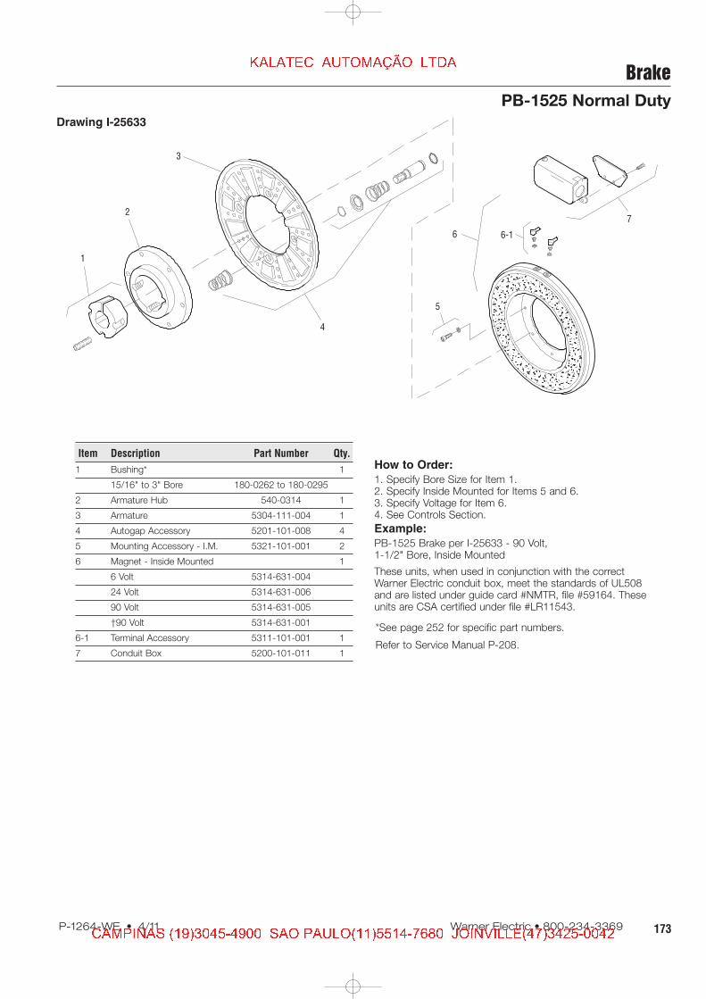
PB-1525 Normal Duty
Drawing I-25633
How to Order:
1. Specify Bore Size for Item 1.2. Specify Inside Mounted for Items 5 and 6.3. Specify Voltage for Item 6.4. See Controls Section.
Example:
PB-1525 Brake per I-25633 - 90 Volt,1-1/2" Bore, Inside Mounted
These units, when used in conjunction with the correctWarner Electric conduit box, meet the standards of UL508and are listed under guide card #NMTR, file #59164. Theseunits are CSA certified under file #LR11543.
175P-1264-WE • 4/11 Warner Electric • 800-234-3369
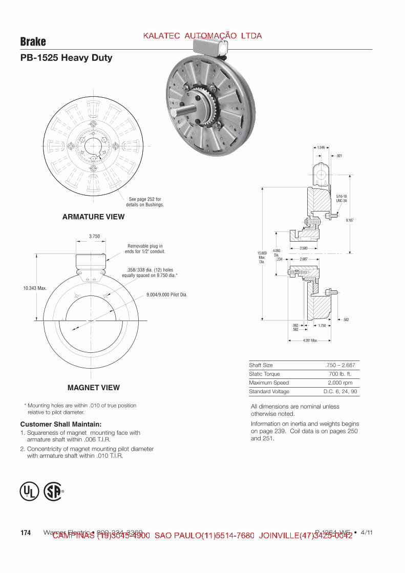
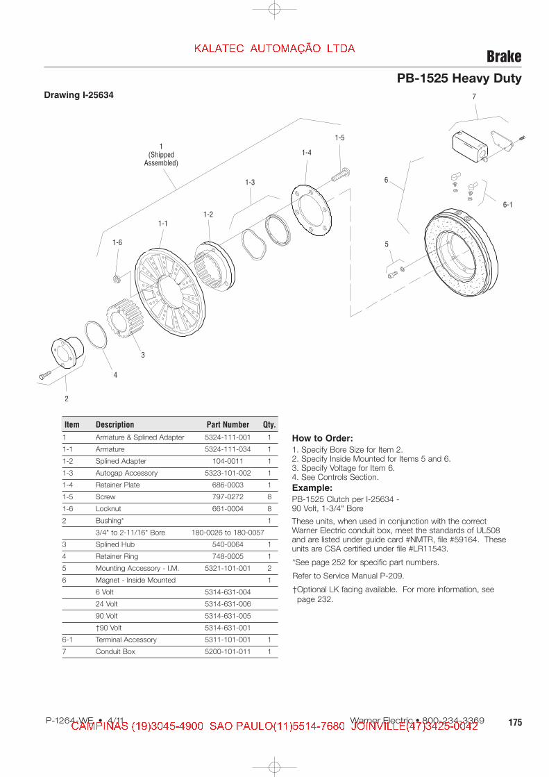
Brake
PB-1525 Heavy Duty
Drawing I-25634
How to Order:
1. Specify Bore Size for Item 2.2. Specify Inside Mounted for Items 5 and 6.3. Specify Voltage for Item 6.4. See Controls Section.
Example:
PB-1525 Clutch per I-25634 -90 Volt, 1-3/4" Bore
These units, when used in conjunction with the correctWarner Electric conduit box, meet the standards of UL508and are listed under guide card #NMTR, file #59164. Theseunits are CSA certified under file #LR11543.
1(Shipped
Assembled)
1-6
1-1
1-2
1-3
1-4
1-5
2
3
4
6
5
6-1
7
Item Description Part Number Qty.
1 Armature & Splined Adapter 5324-111-001 1
1-1 Armature 5324-111-034 1
1-2 Splined Adapter 104-0011 1
1-3 Autogap Accessory 5323-101-002 1
1-4 Retainer Plate 686-0003 1
1-5 Screw 797-0272 8
1-6 Locknut 661-0004 8
2 Bushing* 1
3/4" to 2-11/16" Bore 180-0026 to 180-0057
3 Splined Hub 540-0064 1
4 Retainer Ring 748-0005 1
5 Mounting Accessory - I.M. 5321-101-001 2
6 Magnet - Inside Mounted 1
6 Volt 5314-631-004
24 Volt 5314-631-006
90 Volt 5314-631-005
†90 Volt 5314-631-001
6-1 Terminal Accessory 5311-101-001 1
7 Conduit Box 5200-101-011 1
*See page 252 for specific part numbers.
Refer to Service Manual P-209.
†Optional LK facing available. For more information, see