60
FTTH ODN´s Professional Supplier
| Date post: | 29-Mar-2016 |
| Category: |
Documents |
| Upload: | lorena-jacome |
| View: | 247 times |
| Download: | 4 times |

FTTH ODN´s Professional Supplier

W W . A L T A L A . N E T A L T A L A T H E N E T W O R K C O M P A N Y
2
Vision
Being recognized as leaders in the provision of both new and second hand Networking
equipment as well as services for the communications industry all over the world.
Mission
Supporting the growth of communications companies through the high quality products
and services we commercialize, allowing at same time, a long term and sustainable
growth of our company and that of our clients
Our People
ALTALA "The Network Company" (A-TNC) has, as part of its team, top
certified Engineers and Consultants trained in different parts of the world with
the sole purpose of serving all your requirements and concerns.
ALTALA "The Network Company" (A-TNC) has a highly qualified Sales Staff,
trained and assertive to meet all our clients' needs.
ALTALA "The Network Company" (A-TNC) has international and local
agreements to provide our customers with the best quality service possible.
ALTALA "The Network Company" (A-TNC) is commercial partners with the
most widely used brands in the communications industry, as can be seen in this
Products section, in order to offer our clients a greater amount of alternatives.
W W . A L T A L A . N E T A L T A L A T H E N E T W O R K C O M P A N Y
3
Fiber Optic Equipment Fiber Optic OTDR`s 4
OTDR TW2000 OTDR TW2800 OTDR TW3000 AFL/Noyes M200-K-Quad OTDR 850/1300/1310/1550 nm
AFL/Noyes M200-SM 1310/ 1550 nm AFL/Noyes C880 Quad OTDR Certification Test Kit AFL/Noyes M200-SM 1310/ 1550 nm AFL/Noyes OFL 250 -50 Single-Mode Handheld OTDR AFL/Noyes OFL 280-100 1310/1550 Single-Mode Handheld
OTDR AFL/Noyes OFL 280-101 1310/1550//1625 SM- Handheld OTDR
AFL/Noyes OFL 280-102 1310/1490/1550 SM- Handheld OTDR AFL/Noyes OFL 280-103 1310/1550/1625 SM- Handheld OTDR EXFO AXS-110-23B SM OTDR
EXFO FTB-150 Hand Held OTDR
EXFO FTB-200 Compact Platform
Fiber Testing Instrument 13 Cable Fault Locator TW3304N Fiber Identifier TW3306 Visual Fault Locator TW3105 Power Meter Power Meter TW3205 Power Meter TW3203R Power Meter TW3208
Laser Source TW3111 Laser Source TW3110 Laser Source TW3109 Laser Source TW3108 Laser Source TW3104
PON Power Meter TW3212 Multi-Meter TW3207
Multi-Meter TW3204 Optical Talk Set TW4103
Optical Variable Attenuator TW3303
Fusion Splicer 19
Fusion Splicer TCW-605 Fusion Splicer TCW-601
Fiber Cleaver TC-300 Fusion Splicer (FFS-70C Type) FFS-60C Type Fusion Splicer FCV-21 Type Fiber Cleaver
Fiber Optic Assemblies 44
Fiber Optic Patch Cord
Optic Fiber Splitter
Fiber Optic Connector
Fiber Optic Adapter
Fiber Optic Attenuator
Optic Fiber Closure
Optical Distribution Frame
Optic Fiber Protection Sleeve
Optic Fiber Tool`s and Kits 54
Optic Fiber Tools
Optic Fiber Tool Kits
Pipeline & Cable Locator
Optical Toolkit TC-405
Optical Toolkit TC-406
FTTx Termination Box
FTTx Cable Series
FIBER OPTIC OTDRs
W W . A L T A L A . N E T A L T A L A T H E N E T W O R K C O M P A N Y
4
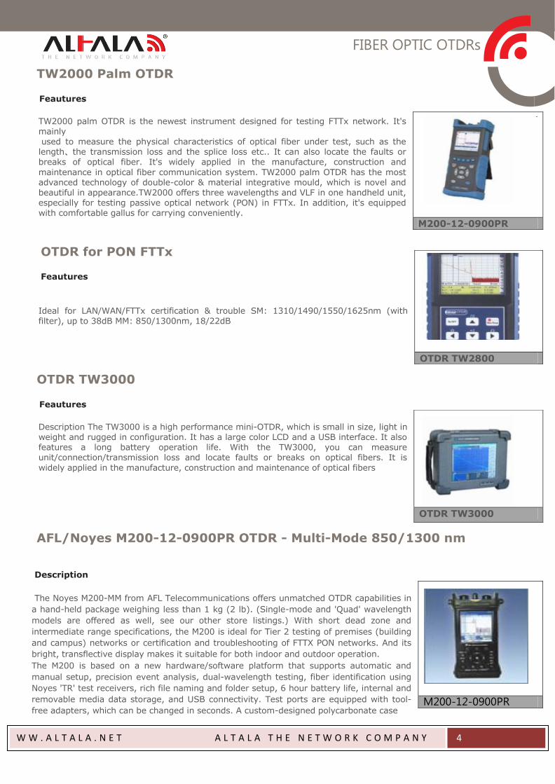
TW2000 Palm OTDR Feautures
TW2000 palm OTDR is the newest instrument designed for testing FTTx network. It's mainly used to measure the physical characteristics of optical fiber under test, such as the length、the transmission loss and the splice loss etc.. It can also locate the faults or breaks of optical fiber. It's widely applied in the manufacture, construction and
maintenance in optical fiber communication system. TW2000 palm OTDR has the most advanced technology of double-color & material integrative mould, which is novel and beautiful in appearance.TW2000 offers three wavelengths and VLF in one handheld unit, especially for testing passive optical network (PON) in FTTx. In addition, it's equipped with comfortable gallus for carrying conveniently.
OTDR for PON FTTx
Feautures
Ideal for LAN/WAN/FTTx certification & trouble SM: 1310/1490/1550/1625nm (with filter), up to 38dB MM: 850/1300nm, 18/22dB
OTDR TW3000 Feautures
Description The TW3000 is a high performance mini-OTDR, which is small in size, light in weight and rugged in configuration. It has a large color LCD and a USB interface. It also features a long battery operation life. With the TW3000, you can measure unit/connection/transmission loss and locate faults or breaks on optical fibers. It is
widely applied in the manufacture, construction and maintenance of optical fibers
AFL/Noyes M200-12-0900PR OTDR - Multi-Mode 850/1300 nm
Description
The Noyes M200-MM from AFL Telecommunications offers unmatched OTDR capabilities in
a hand-held package weighing less than 1 kg (2 lb). (Single-mode and 'Quad' wavelength
models are offered as well, see our other store listings.) With short dead zone and
intermediate range specifications, the M200 is ideal for Tier 2 testing of premises (building
and campus) networks or certification and troubleshooting of FTTX PON networks. And its
bright, transflective display makes it suitable for both indoor and outdoor operation.
The M200 is based on a new hardware/software platform that supports automatic and
manual setup, precision event analysis, dual-wavelength testing, fiber identification using
Noyes 'TR' test receivers, rich file naming and folder setup, 6 hour battery life, internal and
removable media data storage, and USB connectivity. Test ports are equipped with tool-
free adapters, which can be changed in seconds. A custom-designed polycarbonate case
M200-12-0900PR
OTDR TW2800
OTDR TW3000
M200-12-0900PR
FIBER OPTIC OTDRs
W W . A L T A L A . N E T A L T A L A T H E N E T W O R K C O M P A N Y
5
and shock-absorbing boot make it our most rugged OTDR ever. Results are saved as industry standard .SOR files, which
can be viewed, printed, and analyzed on a PC using free-ware available to you and your customers (go to
www.afltele.com to download). Unit firmware, user settings, and test results are saved in non-volatile memory. Thus the
M200 may be stored with battery removed for an extended period of time and still be up and running in seconds.
Specs:
Details
Handheld, 0.9 kg (2 lb)
850/1300/1310/1550 nm
1.5 m (typ.) event dead zone
22 dB (MM), 26 dB (SM) dynamic range
Integrated VFL (650 nm)
Tool-free, switchable adapters (ST/SC/FC)
Bellcore (GR-196) .SOR file format
Tool-free LiIon battery (6 hour life)
Transflective (indoor/outdoor) touchscreen display
USB Host and Function Ports
USB Flash Drive
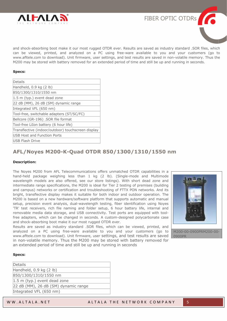
AFL/Noyes M200-K-Quad OTDR 850/1300/1310/1550 nm
Description:
The Noyes M200 from AFL Telecommunications offers unmatched OTDR capabilities in a
hand-held package weighing less than 1 kg (2 lb). (Single-mode and Multimode
wavelength models are also offered, see our store listings). With short dead zone and
intermediate range specifications, the M200 is ideal for Tier 2 testing of premises (building
and campus) networks or certification and troubleshooting of FTTX PON networks. And its
bright, transflective display makes it suitable for both indoor and outdoor operation. The
M200 is based on a new hardware/software platform that supports automatic and manual
setup, precision event analysis, dual-wavelength testing, fiber identification using Noyes
'TR' test receivers, rich file naming and folder setup, 6 hour battery life, internal and
removable media data storage, and USB connectivity. Test ports are equipped with tool-
free adapters, which can be changed in seconds. A custom-designed polycarbonate case
and shock-absorbing boot make it our most rugged OTDR ever.
Results are saved as industry standard .SOR files, which can be viewed, printed, and
analyzed on a PC using free-ware available to you and your customers (go to
www.afltele.com to download). Unit firmware, user settings, and test results are saved in non-volatile memory. Thus the M200 may be stored with battery removed for an extended period of time and still be up and running in seconds
Specs:
Details
Handheld, 0.9 kg (2 lb)
850/1300/1310/1550 nm
1.5 m (typ.) event dead zone
22 dB (MM), 26 dB (SM) dynamic range
Integrated VFL (650 nm)
M200-00-0900PRM200-00-
0900PR

FIBER OPTIC OTDRs
W W . A L T A L A . N E T A L T A L A T H E N E T W O R K C O M P A N Y
6
Tool-free, switchable adapters (ST/SC/FC)
Bellcore (GR-196) .SOR file format
Tool-free LiIon battery (6 hour life)
Transflective (indoor/outdoor) touchscreen display
USB Host and Function Ports
USB Flash Drive
AFL/Noyes C880 Quad OTDR Certification Test Kit
Description:
Combining two C840 Certification Testers, the Noyes C880 QUAD Certification Test Kit from
AFL Telecommunications is designed for testing and troubleshooting both multimode and
single-mode fiber links. Each tester includes an integrated Visual Fault Locator (VFL, 650
nm), both single-mode (Laser 1310/1550 nm) and multimode (LED 850/1300 nm) Optical
Light Sources (OLS), and an Optical Power Meter (OPM). Each tester may be used alone as
a traditional power meter, light source or visual fault locator.
In Auto Test mode, the user may perform certification tests to one of the industry cabling
standards (TIA, ISO, EN), one or more application standards, or a user-defined loss/length
limit. Certification reports may be generated based on the selected standards and rules
using PC reporting software. The transflective touch screen display of the C840 tester is
suitable for both indoor and outdoor operation. Thousands of test results may be stored
internally for transfer to a computer via a USB cable or a standard USB drive. Once test data is transferred to a
computer, the supplied Windows® compatible software allows technicians to view, print, and generate professional
certification reports
Specs:
Details
Handheld, 0.9 kg (2 lb)
Integrated OPM, OLS, and VFL (650 nm)
850/1300 nm - LED and 1310/1550 nm - Laser sources
Dual-wavelength certification Pass/Fail
Two fibers bi-directional and single fiber testing
Transflective (indoor/outdoor) touch screen display
Tool-free, switchable adapters
Rechargeable Li-Ion battery (> 8 hours) or AC power
USB host and function ports
Internal (1000s test results) and USB storage
Windows® compatible software
C880-100-LP1-S1
FIBER OPTIC OTDRs
W W . A L T A L A . N E T A L T A L A T H E N E T W O R K C O M P A N Y
7
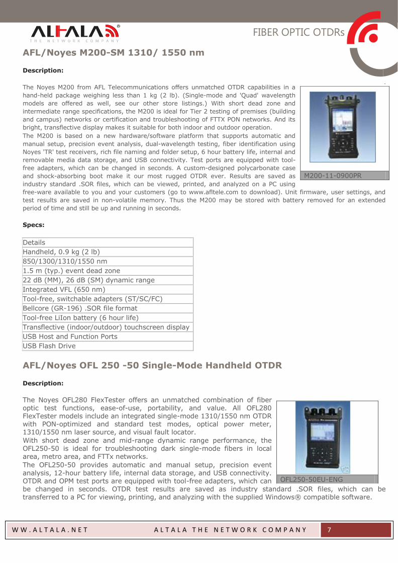
AFL/Noyes M200-SM 1310/ 1550 nm
Description:
The Noyes M200 from AFL Telecommunications offers unmatched OTDR capabilities in a
hand-held package weighing less than 1 kg (2 lb). (Single-mode and 'Quad' wavelength
models are offered as well, see our other store listings.) With short dead zone and
intermediate range specifications, the M200 is ideal for Tier 2 testing of premises (building
and campus) networks or certification and troubleshooting of FTTX PON networks. And its
bright, transflective display makes it suitable for both indoor and outdoor operation.
The M200 is based on a new hardware/software platform that supports automatic and
manual setup, precision event analysis, dual-wavelength testing, fiber identification using
Noyes 'TR' test receivers, rich file naming and folder setup, 6 hour battery life, internal and
removable media data storage, and USB connectivity. Test ports are equipped with tool-
free adapters, which can be changed in seconds. A custom-designed polycarbonate case
and shock-absorbing boot make it our most rugged OTDR ever. Results are saved as
industry standard .SOR files, which can be viewed, printed, and analyzed on a PC using
free-ware available to you and your customers (go to www.afltele.com to download). Unit firmware, user settings, and
test results are saved in non-volatile memory. Thus the M200 may be stored with battery removed for an extended
period of time and still be up and running in seconds.
Specs:
Details
Handheld, 0.9 kg (2 lb)
850/1300/1310/1550 nm
1.5 m (typ.) event dead zone
22 dB (MM), 26 dB (SM) dynamic range
Integrated VFL (650 nm)
Tool-free, switchable adapters (ST/SC/FC)
Bellcore (GR-196) .SOR file format
Tool-free LiIon battery (6 hour life)
Transflective (indoor/outdoor) touchscreen display
USB Host and Function Ports
USB Flash Drive
AFL/Noyes OFL 250 -50 Single-Mode Handheld OTDR
Description:
The Noyes OFL280 FlexTester offers an unmatched combination of fiber
optic test functions, ease-of-use, portability, and value. All OFL280 FlexTester models include an integrated single-mode 1310/1550 nm OTDR with PON-optimized and standard test modes, optical power meter, 1310/1550 nm laser source, and visual fault locator.
With short dead zone and mid-range dynamic range performance, the OFL250-50 is ideal for troubleshooting dark single-mode fibers in local area, metro area, and FTTx networks.
The OFL250-50 provides automatic and manual setup, precision event
analysis, 12-hour battery life, internal data storage, and USB connectivity. OTDR and OPM test ports are equipped with tool-free adapters, which can be changed in seconds. OTDR test results are saved as industry standard .SOR files, which can be transferred to a PC for viewing, printing, and analyzing with the supplied Windows® compatible software.
M200-11-0900PR
OFL250-50EU-ENG
FIBER OPTIC OTDRs
W W . A L T A L A . N E T A L T A L A T H E N E T W O R K C O M P A N Y
8
Specs:
Details
Rugged, handheld and light weight
1.5 m event dead zone
26 dB dynamic range
Integrated OPM, OLS, VFL
Tool-free, switchable adapters for OTDR and OPM ports
Internal storage (>1000 OTDR traces in standard .SOR format)
High-contrast display is clear and bright in any lighting condition, including direct sunlight
Transfer test results to a PC via USB
Rechargeable 12-hour Li-Ion battery or AC power
Windows® compatible software to view, print, and archive test records
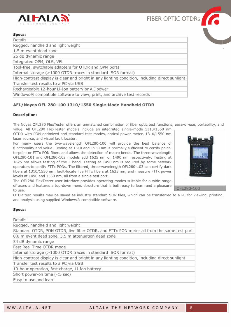
AFL/Noyes OFL 280-100 1310/1550 Single-Mode Handheld OTDR
Description:
The Noyes OFL280 FlexTester offers an unmatched combination of fiber optic test functions, ease-of-use, portability, and
value. All OFL280 FlexTester models include an integrated single-mode 1310/1550 nm
OTDR with PON-optimized and standard test modes, optical power meter, 1310/1550 nm
laser source, and visual fault locator.
For many users the two-wavelength OFL280-100 will provide the best balance of
functionality and value. Testing at 1310 and 1550 nm is normally sufficient to certify point-
to-point or FTTx PON fibers and allows the detection of macro bends. The three-wavelength
OFL280-101 and OFL280-102 models add 1625 nm or 1490 nm respectively. Testing at
1625 nm allows testing of the L band. Testing at 1490 nm is required by some network
operators to certify FTTx PONs. The filtered, three-wavelength OFL280-103 can certify dark
fibers at 1310/1550 nm, fault-locate live FTTx fibers at 1625 nm, and measure FTTx power
levels at 1490 and 1550 nm, all from a single test port.
The OFL280 FlexTester user interface provides operating modes suitable for a wide range
of users and features a top-down menu structure that is both easy to learn and a pleasure
to use.
OTDR test results may be saved as industry standard SOR files, which can be transferred to a PC for viewing, printing,
and analysis using supplied Windows® compatible software.
Specs:
Details
Rugged, handheld and light weight
Standard OTDR, PON OTDR, live fiber OTDR, and FTTx PON meter all from the same test port
0.8 m event dead zone, 3.5 m attenuation dead zone
34 dB dynamic range
Fast Real Time OTDR mode
Internal storage (>1000 OTDR traces in standard .SOR format)
High-contrast display is clear and bright in any lighting condition, including direct sunlight
Transfer test results to a PC via USB
10-hour operation, fast charge, Li-Ion battery
Short power-on time (<5 sec)
Easy to use and learn
OFL280-100
FIBER OPTIC OTDRs
W W . A L T A L A . N E T A L T A L A T H E N E T W O R K C O M P A N Y
9
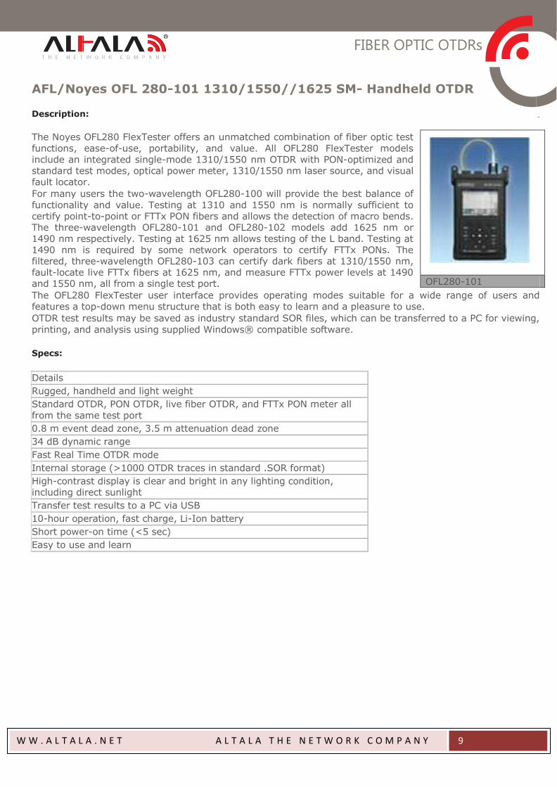
AFL/Noyes OFL 280-101 1310/1550//1625 SM- Handheld OTDR
Description:
The Noyes OFL280 FlexTester offers an unmatched combination of fiber optic test
functions, ease-of-use, portability, and value. All OFL280 FlexTester models include an integrated single-mode 1310/1550 nm OTDR with PON-optimized and standard test modes, optical power meter, 1310/1550 nm laser source, and visual fault locator.
For many users the two-wavelength OFL280-100 will provide the best balance of
functionality and value. Testing at 1310 and 1550 nm is normally sufficient to certify point-to-point or FTTx PON fibers and allows the detection of macro bends. The three-wavelength OFL280-101 and OFL280-102 models add 1625 nm or 1490 nm respectively. Testing at 1625 nm allows testing of the L band. Testing at 1490 nm is required by some network operators to certify FTTx PONs. The filtered, three-wavelength OFL280-103 can certify dark fibers at 1310/1550 nm, fault-locate live FTTx fibers at 1625 nm, and measure FTTx power levels at 1490 and 1550 nm, all from a single test port.
The OFL280 FlexTester user interface provides operating modes suitable for a wide range of users and features a top-down menu structure that is both easy to learn and a pleasure to use.
OTDR test results may be saved as industry standard SOR files, which can be transferred to a PC for viewing,
printing, and analysis using supplied Windows® compatible software.
Specs:
Details
Rugged, handheld and light weight
Standard OTDR, PON OTDR, live fiber OTDR, and FTTx PON meter all
from the same test port
0.8 m event dead zone, 3.5 m attenuation dead zone
34 dB dynamic range
Fast Real Time OTDR mode
Internal storage (>1000 OTDR traces in standard .SOR format)
High-contrast display is clear and bright in any lighting condition, including direct sunlight
Transfer test results to a PC via USB
10-hour operation, fast charge, Li-Ion battery
Short power-on time (<5 sec)
Easy to use and learn
OFL280-101
FIBER OPTIC OTDRs
W W . A L T A L A . N E T A L T A L A T H E N E T W O R K C O M P A N Y
10
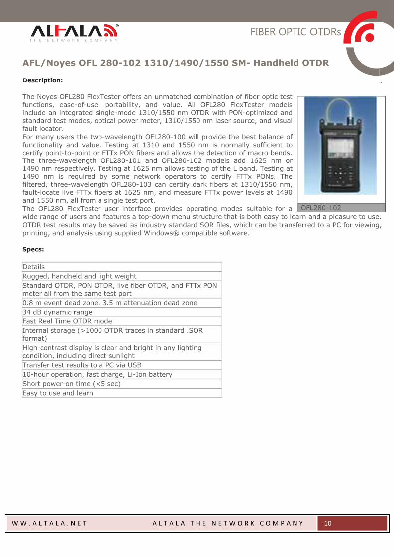
AFL/Noyes OFL 280-102 1310/1490/1550 SM- Handheld OTDR
Description:
The Noyes OFL280 FlexTester offers an unmatched combination of fiber optic test
functions, ease-of-use, portability, and value. All OFL280 FlexTester models include an integrated single-mode 1310/1550 nm OTDR with PON-optimized and standard test modes, optical power meter, 1310/1550 nm laser source, and visual fault locator.
For many users the two-wavelength OFL280-100 will provide the best balance of
functionality and value. Testing at 1310 and 1550 nm is normally sufficient to certify point-to-point or FTTx PON fibers and allows the detection of macro bends. The three-wavelength OFL280-101 and OFL280-102 models add 1625 nm or 1490 nm respectively. Testing at 1625 nm allows testing of the L band. Testing at 1490 nm is required by some network operators to certify FTTx PONs. The filtered, three-wavelength OFL280-103 can certify dark fibers at 1310/1550 nm, fault-locate live FTTx fibers at 1625 nm, and measure FTTx power levels at 1490 and 1550 nm, all from a single test port.
The OFL280 FlexTester user interface provides operating modes suitable for a wide range of users and features a top-down menu structure that is both easy to learn and a pleasure to use.
OTDR test results may be saved as industry standard SOR files, which can be transferred to a PC for viewing,
printing, and analysis using supplied Windows® compatible software.
Specs:
Details
Rugged, handheld and light weight
Standard OTDR, PON OTDR, live fiber OTDR, and FTTx PON
meter all from the same test port
0.8 m event dead zone, 3.5 m attenuation dead zone
34 dB dynamic range
Fast Real Time OTDR mode
Internal storage (>1000 OTDR traces in standard .SOR format)
High-contrast display is clear and bright in any lighting condition, including direct sunlight
Transfer test results to a PC via USB
10-hour operation, fast charge, Li-Ion battery
Short power-on time (<5 sec)
Easy to use and learn
OFL280-102
FIBER OPTIC OTDRs
W W . A L T A L A . N E T A L T A L A T H E N E T W O R K C O M P A N Y
11
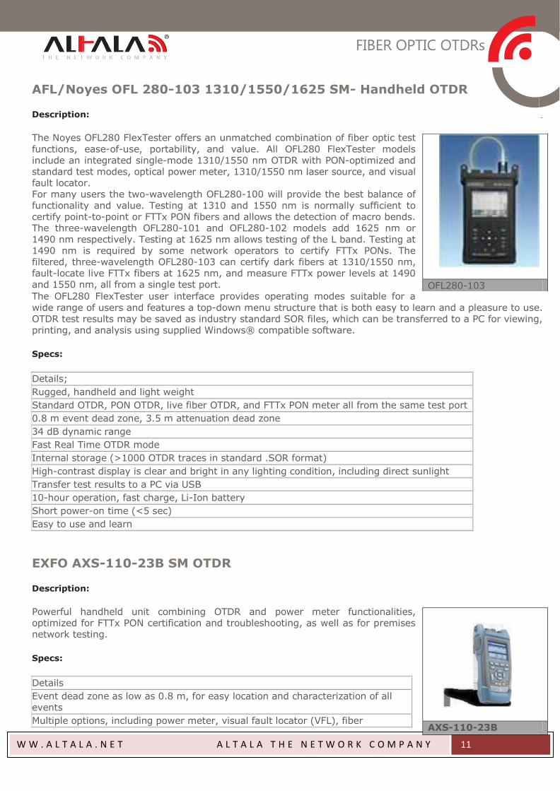
AFL/Noyes OFL 280-103 1310/1550/1625 SM- Handheld OTDR
Description:
The Noyes OFL280 FlexTester offers an unmatched combination of fiber optic test
functions, ease-of-use, portability, and value. All OFL280 FlexTester models include an integrated single-mode 1310/1550 nm OTDR with PON-optimized and standard test modes, optical power meter, 1310/1550 nm laser source, and visual fault locator. For many users the two-wavelength OFL280-100 will provide the best balance of functionality and value. Testing at 1310 and 1550 nm is normally sufficient to certify point-to-point or FTTx PON fibers and allows the detection of macro bends. The three-wavelength OFL280-101 and OFL280-102 models add 1625 nm or 1490 nm respectively. Testing at 1625 nm allows testing of the L band. Testing at 1490 nm is required by some network operators to certify FTTx PONs. The filtered, three-wavelength OFL280-103 can certify dark fibers at 1310/1550 nm, fault-locate live FTTx fibers at 1625 nm, and measure FTTx power levels at 1490 and 1550 nm, all from a single test port.
The OFL280 FlexTester user interface provides operating modes suitable for a
wide range of users and features a top-down menu structure that is both easy to learn and a pleasure to use. OTDR test results may be saved as industry standard SOR files, which can be transferred to a PC for viewing, printing, and analysis using supplied Windows® compatible software.
Specs:
Details;
Rugged, handheld and light weight
Standard OTDR, PON OTDR, live fiber OTDR, and FTTx PON meter all from the same test port
0.8 m event dead zone, 3.5 m attenuation dead zone
34 dB dynamic range
Fast Real Time OTDR mode
Internal storage (>1000 OTDR traces in standard .SOR format)
High-contrast display is clear and bright in any lighting condition, including direct sunlight
Transfer test results to a PC via USB
10-hour operation, fast charge, Li-Ion battery
Short power-on time (<5 sec)
Easy to use and learn
EXFO AXS-110-23B SM OTDR
Description:
Powerful handheld unit combining OTDR and power meter functionalities, optimized for FTTx PON certification and troubleshooting, as well as for premises network testing.
Specs:
Details
Event dead zone as low as 0.8 m, for easy location and characterization of all events
Multiple options, including power meter, visual fault locator (VFL), fiber
OFL280-103
AXS-110-23B
FIBER OPTIC OTDRs
W W . A L T A L A . N E T A L T A L A T H E N E T W O R K C O M P A N Y
12
inspection probe, printer and IP testing
Fault Finder mode, for quick identification/location of fiber breaks
Smart software option providing pass/fail status at all wavelengths, as well as
span loss, ORL, fiber length and macrobend locations in a single window
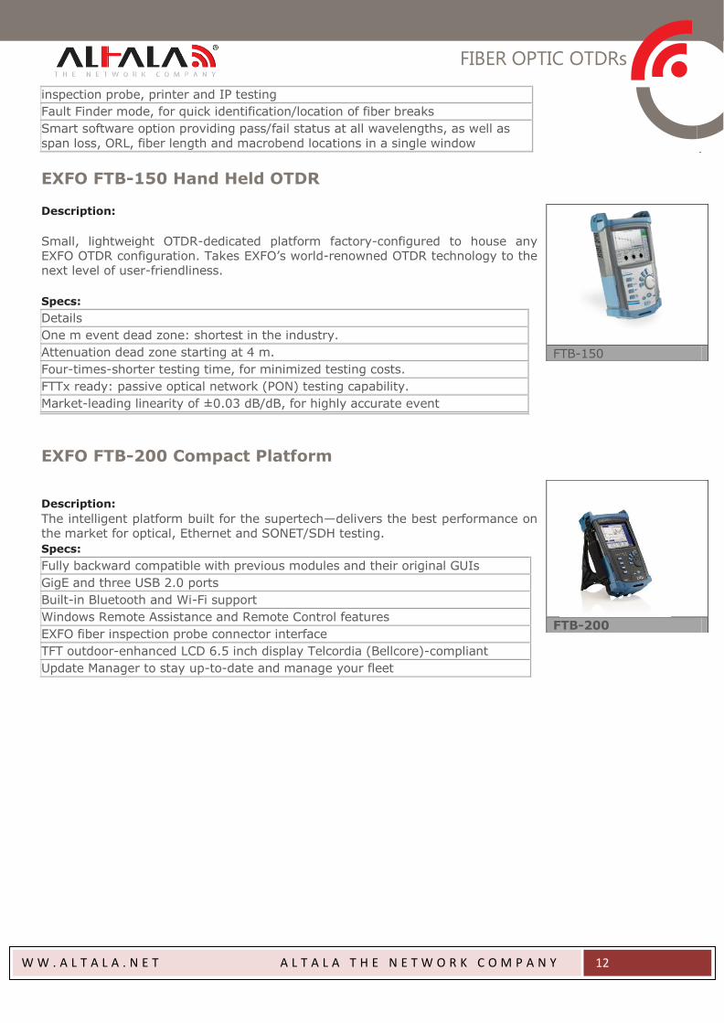
EXFO FTB-150 Hand Held OTDR
Description:
Small, lightweight OTDR-dedicated platform factory-configured to house any EXFO OTDR configuration. Takes EXFO’s world-renowned OTDR technology to the next level of user-friendliness.
Specs:
Details
One m event dead zone: shortest in the industry.
Attenuation dead zone starting at 4 m.
Four-times-shorter testing time, for minimized testing costs.
FTTx ready: passive optical network (PON) testing capability.
Market-leading linearity of ±0.03 dB/dB, for highly accurate event
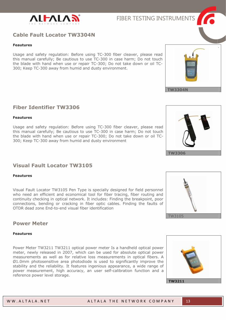
EXFO FTB-200 Compact Platform
Description:
The intelligent platform built for the supertech—delivers the best performance on the market for optical, Ethernet and SONET/SDH testing.
Specs:
Fully backward compatible with previous modules and their original GUIs
GigE and three USB 2.0 ports
Built-in Bluetooth and Wi-Fi support
Windows Remote Assistance and Remote Control features
EXFO fiber inspection probe connector interface
TFT outdoor-enhanced LCD 6.5 inch display Telcordia (Bellcore)-compliant
Update Manager to stay up-to-date and manage your fleet
FTB-150
FTB-200
FIBER TESTING INSTRUMENTS
W W . A L T A L A . N E T A L T A L A T H E N E T W O R K C O M P A N Y
13
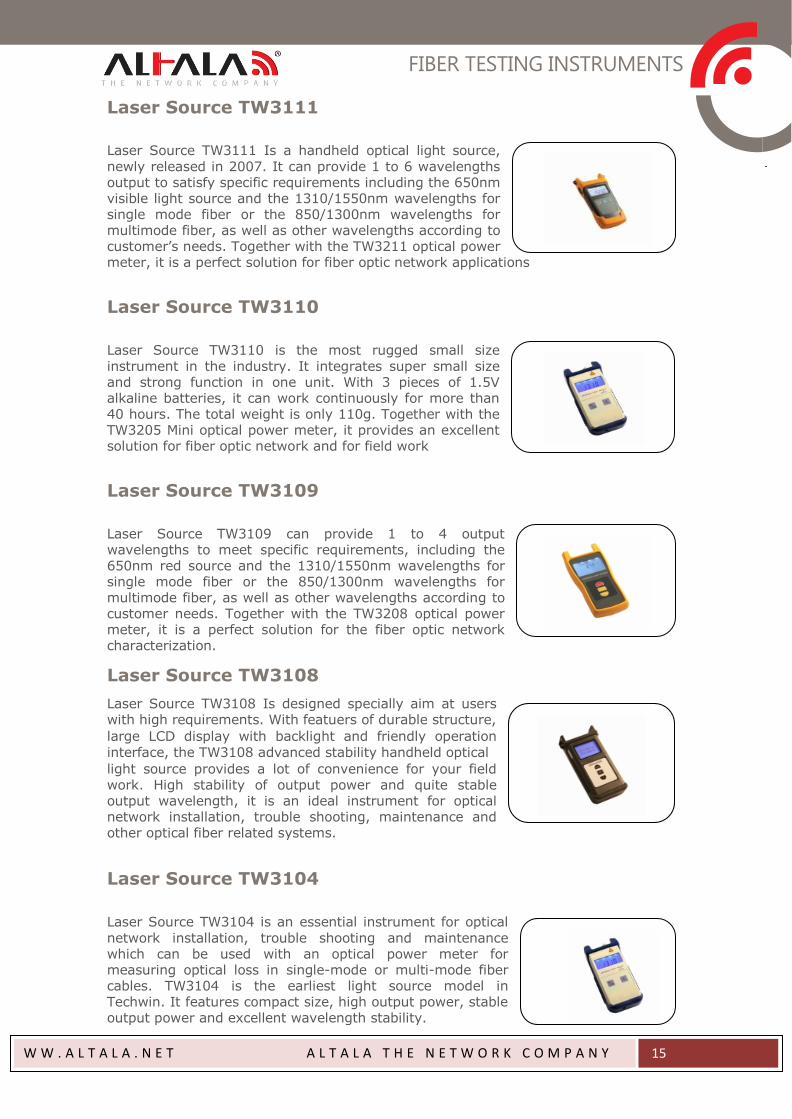
Cable Fault Locator TW3304N
Feautures
Usage and safety regulation: Before using TC-300 fiber cleaver, please read
this manual carefully; Be cautious to use TC-300 in case harm; Do not touch the blade with hand when use or repair TC-300; Do not take down or oil TC-300; Keep TC-300 away from humid and dusty environment.
Fiber Identifier TW3306
Feautures
Usage and safety regulation: Before using TC-300 fiber cleaver, please read
this manual carefully; Be cautious to use TC-300 in case harm; Do not touch the blade with hand when use or repair TC-300; Do not take down or oil TC-300; Keep TC-300 away from humid and dusty environment
Visual Fault Locator TW3105
Feautures
Visual Fault Locator TW3105 Pen Type is specially designed for field personnel
who need an efficient and economical tool for fiber tracing, fiber routing and continuity checking in optical network. It includes: Finding the breakpoint, poor connections, bending or cracking in fiber optic cables. Finding the faults of OTDR dead zone End-to-end visual fiber identification
Power Meter
Feautures
Power Meter TW3211 TW3211 optical power meter Is a handheld optical power
meter, newly released in 2007, which can be used for absolute optical power measurements as well as for relative loss measurements in optical fibers. A Ø1.0mm photosensitive area photodiode is used to significantly improve the stability and the reliability. It features ingenious appearance, a wide range of power measurement, high accuracy, an user self-calibration function and a reference power level storage.
TW3304N
TW3306
TW3105
TW3211

FIBER TESTING INSTRUMENTS
W W . A L T A L A . N E T A L T A L A T H E N E T W O R K C O M P A N Y
14
Power Meter
TW3205
Power Meter TW3205 TW3205 mini handheld optical power meter is the most lightweight and compact in size testing instrument. It features ease-of-use and economy advantages and can be used for absolute power measurement in optical fibers. TW3205 in combination with the TW3110 mini handheld light source become the most portable and advantageous testing pair
Power Meter
TW3203R
Power Meter TW3203R TW3203R handheld optical power meter is the oldest portable test instrment in the Techwin power meter series. It features compact size, ease-of-use and economy advantages. It can be used for absolute optical power measurements as well as for relative loss measurements of optical fibers. TW3203R is an essential test instrument in Optical Communications, CATV and other Fiber Optic measurements.
Power Meter
TW3208
TW3208 handheld optical power meter is a compact and an easy-
to-use testing instrument for optical fiber networks, which can be used for absolute optical powermeasurements as well as for relative loss measurements in optical fibers. It features ingenious appearance, wide range of power measurement, high accuracy and user self-calibration function with high performance-to-price ratio.
Power Meter
TW3206
Power Meter TW3206 TW3206 intelligent handheld power meter is
a perfect testing instrument for both laboratory and field applications in optical fibers. It features friendly User Interface with menu operation, automatic frequency identification , large LCD display with backlight and dual-way powering system. The internal microprocessor and linear amplifier technology ensure the long-term accuracy. In addition, TW3206 has a memory capacity of 240 records and can transfer the measurement data through a RS232 communication port to a PC for printing or editing. Moreover, it can also perform on-line data upload after programme contro
FIBER TESTING INSTRUMENTS
W W . A L T A L A . N E T A L T A L A T H E N E T W O R K C O M P A N Y
15
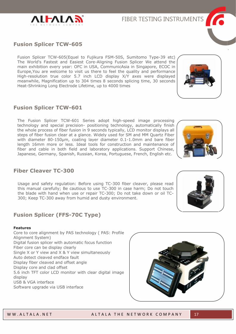
Laser Source TW3111
Laser Source TW3111 Is a handheld optical light source,
newly released in 2007. It can provide 1 to 6 wavelengths output to satisfy specific requirements including the 650nm visible light source and the 1310/1550nm wavelengths for single mode fiber or the 850/1300nm wavelengths for multimode fiber, as well as other wavelengths according to customer’s needs. Together with the TW3211 optical power meter, it is a perfect solution for fiber optic network applications
Laser Source TW3110
Laser Source TW3110 is the most rugged small size
instrument in the industry. It integrates super small size and strong function in one unit. With 3 pieces of 1.5V alkaline batteries, it can work continuously for more than 40 hours. The total weight is only 110g. Together with the TW3205 Mini optical power meter, it provides an excellent solution for fiber optic network and for field work
Laser Source TW3109
Laser Source TW3109 can provide 1 to 4 output wavelengths to meet specific requirements, including the 650nm red source and the 1310/1550nm wavelengths for single mode fiber or the 850/1300nm wavelengths for multimode fiber, as well as other wavelengths according to customer needs. Together with the TW3208 optical power meter, it is a perfect solution for the fiber optic network characterization.
Laser Source TW3108
Laser Source TW3108 Is designed specially aim at users with high requirements. With featuers of durable structure,
large LCD display with backlight and friendly operation
interface, the TW3108 advanced stability handheld optical
light source provides a lot of convenience for your field work. High stability of output power and quite stable output wavelength, it is an ideal instrument for optical network installation, trouble shooting, maintenance and other optical fiber related systems.
Laser Source TW3104
Laser Source TW3104 is an essential instrument for optical
network installation, trouble shooting and maintenance which can be used with an optical power meter for measuring optical loss in single-mode or multi-mode fiber cables. TW3104 is the earliest light source model in Techwin. It features compact size, high output power, stable output power and excellent wavelength stability.

FIBER TESTING INSTRUMENTS
W W . A L T A L A . N E T A L T A L A T H E N E T W O R K C O M P A N Y
16
PON Power Meter TW3212
Power Meter TW3212 This new PON power meter aims at the FTTx application and maintenance which can be used to test and estimate the signals of the voice, data and video at the same time. It is an essential and ideal tool for the construction and maintenance of the PON projects
Multi-Meter TW3207
Multi-Meter TW3204
Multi-Meter TW3204 integrates both an optical power meter module and an optical
light source module and can perform closed-loop tests by using both modules, and can also work individually. It is specifically designed for technical support personnel to test a variety of instruments with a single meter and thus satisfy the user by providing a choice of greater convenience and more advantages.
Optical Talk Set TW4103
Optical Talk Set TW4103 is an intelligent and efficient instrument that combines in
one set the functions of both a digital optical phone and a stabilized light source. It is widely used in operations of installation, optical testing, maintenance and fiber attenuation value testing in data network, CATV and Telecommunication network. The TW4103 Talk Set can carry out full-duplex communication with high quality connection and not be affected by distance
Optical Variable Attenuator TW3303
The Perfect Handhold Tester Series Optical Variable Attenuator TW3303 TW3303
handhold optical variable attenuator is used for continuously variable optical signal attenuation. As the attenuator is used in the laser system for the on-line testing, there, thereforeTW3303 can be used in the digital system of communication devices (such as: PHD, SDH) and also in the system of adopting analog modulation (CATV)
Multi-Meter TW3207 integrates the functions of an intelligent optical power meter module and of a highly stable light source module in one unit which can perform closed-loop tests by incorporating both modules. Individual regimes of operation can also be manually chosen using menu operation to switch functions. A perfect combination to make your optical fiber tests a lot more convenient
FIBER TESTING INSTRUMENTS
W W . A L T A L A . N E T A L T A L A T H E N E T W O R K C O M P A N Y
17
Fusion Splicer TCW-605
Fusion Splicer TCW-605(Equel to Fujikura FSM-50S, Sumitomo Type-39 etc) The World's Fastest and Easiest Core-Aligning Fusion Splicer We attend the main exhibition every year: OFC in USA, CommunicAsia in Singapore, ECOC in Europe,You are welcome to visit us there to feel the quality and performance High-resolution true color 5.7 inch LCD display X/Y axes were displayed meanwhile, Magnification up to 304 times 8 seconds splicing time, 30 seconds Heat-Shrinking Long Electrode Lifetime, up to 4000 times
Fusion Splicer TCW-601
The Fusion Splicer TCW-601 Series adopt high-speed image processing technology and special precision- positioning technology, automatically finish the whole process of fiber fusion in 9 seconds typically, LCD monitor displays all steps of fiber fusion clear at a glance. Widely used for SM and MM Quartz Fiber with diameter 80-150μm, coating layer diameter 0.1-1.0mm and bare fiber length 16mm more or less. Ideal tools for construction and maintenance of fiber and cable in both field and laboratory applications. Support Chinese, Japanese, Germany, Spanish, Russian, Korea, Portuguese, French, English etc.
Fiber Cleaver TC-300
Usage and safety regulation: Before using TC-300 fiber cleaver, please read
this manual carefully; Be cautious to use TC-300 in case harm; Do not touch the blade with hand when use or repair TC-300; Do not take down or oil TC-300; Keep TC-300 away from humid and dusty environment.
Fusion Splicer (FFS-70C Type)
Features
Core to core alignment by PAS technology ( PAS: Profile
Alignment System)
Digital fusion splicer with automatic focus function
Fiber core can be display clearly
Single X or Y view and X & Y view simultaneously
Auto detect cleaved endface fault
Display fiber cleaved and offset angle
Display core and clad offset
5.6 inch TFT color LCD monitor with clear digital image
display
USB & VGA interface
Software upgrade via USB interface
FIBER TESTING INSTRUMENTS
W W . A L T A L A . N E T A L T A L A T H E N E T W O R K C O M P A N Y
18
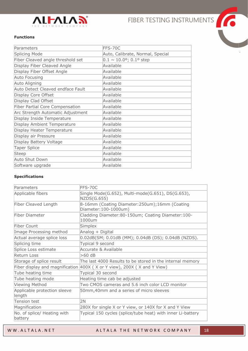
Functions
Parameters FFS-70C
Splicing Mode Auto, Calibrate, Normal, Special
Fiber Cleaved angle threshold set 0.1 ~ 10.0º; 0.1º step
Display Fiber Cleaved Angle Available
Display Fiber Offset Angle Available
Auto Focusing Available
Auto Aligning Available
Auto Detect Cleaved endface Fault Available
Display Core Offset Available
Display Clad Offset Available
Fiber Partial Core Compensation Available
Arc Strength Automatic Adjustment Available
Display Inside Temperature Available
Display Ambient Temperature Available
Display Heater Temperature Available
Display air Pressure Available
Display Battery Voltage Available
Taper Splice Available
Steep Available
Auto Shut Down Available
Software upgrade Available
Specifications
Parameters FFS-70C
Applicable fibers Single Mode(G.652), Multi-mode(G.651), DS(G.653), NZDS(G.655)
Fiber Cleaved Length 8-16mm (Coating Diameter:250um);16mm (Coating Diameter:100-1000um)
Fiber Diameter Cladding Diameter:80-150um; Coating Diameter:100-
1000um
Fiber Count Simplex
Image Processing method Analog + Digital
Actual average splice loss 0.02dB(SM; 0.01dB (MM); 0.04dB (DS); 0.04dB (NZDS).
Splicing time Typical 9 second
Splice Loss estimate Accurate & Available
Return Loss >60 dB
Storage of splice result The last 4000 Results to be stored in the internal memory
Fiber display and magnification 400X ( X or Y view), 200X ( X and Y View)
Tube heating time Typical 30 second
Tube heating mode Heating time cab be adjusted
Viewing Method Two CMOS cameras and 5.6 inch color LCD monitor
Applicable protection sleeve
length
50mm,40mm and a series of micro sleeves
Tension test 2N
Magnification 280X for single X or Y view, or 140X for X and Y View
No. of splice/ Heating with
battery
Typical 150 cycles (splice/tube heat) with inner Li-battery
FIBER TESTING INSTRUMENTS
W W . A L T A L A . N E T A L T A L A T H E N E T W O R K C O M P A N Y
19
Display screen 5 inch color LCD monitor
Image change over The fiber image is turned upside down
Terminals USB
Operating condition 0-5000m above seal level, 0-95% RH and -10 ~ 50℃
Respectively. Max wind velocity of 15m/s
Power supply AC 100 ~ 240V with AC adaptor, Inner Li-battery (8000m
AH)
Dimensions 150mm(W) x 150mm (D) x 150mm (H)
Weight 2.5 kg excluding battery, 3.0kg including battery
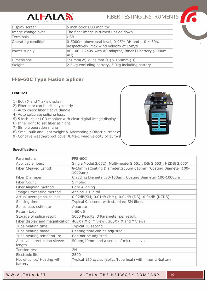
FFS-60C Type Fusion Splicer
Features
1) Both X and Y axis display;
2) Fiber core can be display clearly
3) Auto check fiber cleave dangle
4) Auto calculate splicing loss;
5) 5 inch color LCD monitor with clear digital image display
6) Inner light to set fiber at night
7) Simple operation menu
8) Small bulk and light weight & Alternating / Direct current available;
9) Concave weatherproof cover & Max. wind velocity of 15m/s
Specifications
Parameters FFS-60C
Applicable fibers Single Mode(G.652), Multi-mode(G.651), DS(G.653), NZDS(G.655)
Fiber Cleaved Length 8-16mm (Coating Diameter:250um);16mm (Coating Diameter:100-
1000um)
Fiber Diameter Cladding Diameter:80-150um; Coating Diameter:100-1000um
Fiber Count Simplex
Fiber Aligning method Core Aligning
Image Processing method Analog + Digital
Actual average splice loss 0.02dB(SM; 0.01dB (MM); 0.04dB (DS); 0.04dB (NZDS).
Splicing time Typical 9 second, with standard SM fiber.
Splice Loss estimate Accurate
Return Loss >60 dB
Storage of splice result 5000 Results, 3 Parameter per result.
Fiber display and magnification 400X ( X or Y view), 200X ( X and Y View)
Tube heating time Typical 30 second
Tube heating mode Heating time cab be adjusted
Tube heating temperature Can not be adjusted
Applicable protection sleeve
length
50mm,40mm and a series of micro sleeves
Tension test 2N
Electrode life 2500
No. of splice/ Heating with
battery
Typical 150 cycles (splice/tube heat) with inner Li-battery
FIBER TESTING INSTRUMENTS
W W . A L T A L A . N E T A L T A L A T H E N E T W O R K C O M P A N Y
20
Display screen 5 inch color LCD monitor
Image change over The fiber image is turned upside down
Terminals RS-232
Operating condition 0-5000m above seal level, 0-95% RH and -10 ~ 50℃
Respectively, Max, wind velocity of 15m/s
Power supply AC 100 ~ 240V with AC adaptor, Inner Li-battery (8000m AH)
Dimensions 172mm(L) x 180mm (W) x 145mm (H)
Weight 3.6 kg excluding battery, 4.1kg including battery
Functions
Parameters FFS-60C
Splicing Mode Auto
Fiber Cleaved angle threshold set 0.5 ~ 8º; 0.5º step
Display Fiber Cleaved Angle Unavailable
Display Fiber Offset Angle Unavailable
Auto Focusing Unavailable
Auto Aligning Available
Auto Detect Cleaved endface Fault Unavailable
Display Core Offset Unavailable
Display Clad Offset Unavailable
Fiber Partial Core Compensation Unavailable
Arc Strength Automatic Adjustment Unavailable
Display Inside Temperature Unavailable
Display Ambient Temperature Unavailable
Display Heater Temperature Unavailable
Taper Splice Unavailable
Sleep Unavailable
Auto Shut Down Unavailable
Software Upgrade Unavailable
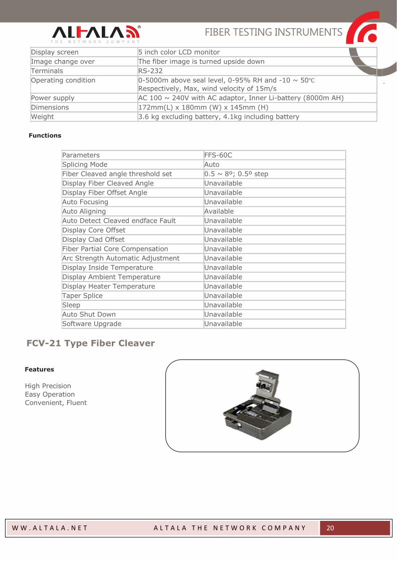
FCV-21 Type Fiber Cleaver
Features
High Precision
Easy Operation
Convenient, Fluent
FIBER TESTING INSTRUMENTS
W W . A L T A L A . N E T A L T A L A T H E N E T W O R K C O M P A N Y
21
Specifications
Parameters FCV-21
Bare Fiber Diameter (mm) Ф125
Outer coat Diameter (mm) 0.25 ~ 0.9
Fiber Type Single tube fiber and Ribbon Fiber (exchangeable)
Cleaved Length (mm) 5 ~ 30
Cleaved Angle 0.5º
Blade Life 0.5 º ~ 15,000 Cleaves
1 º ~ 36,000 Cleaves
(3000 Cleaves – Ribbon Fiber)
Mode Semiautomatic
Dimensions (mm) 58x55x48
Weight (g) 260
OPTICAL FIBER CLOSURES
W W . A L T A L A . N E T A L T A L A T H E N E T W O R K C O M P A N Y
22
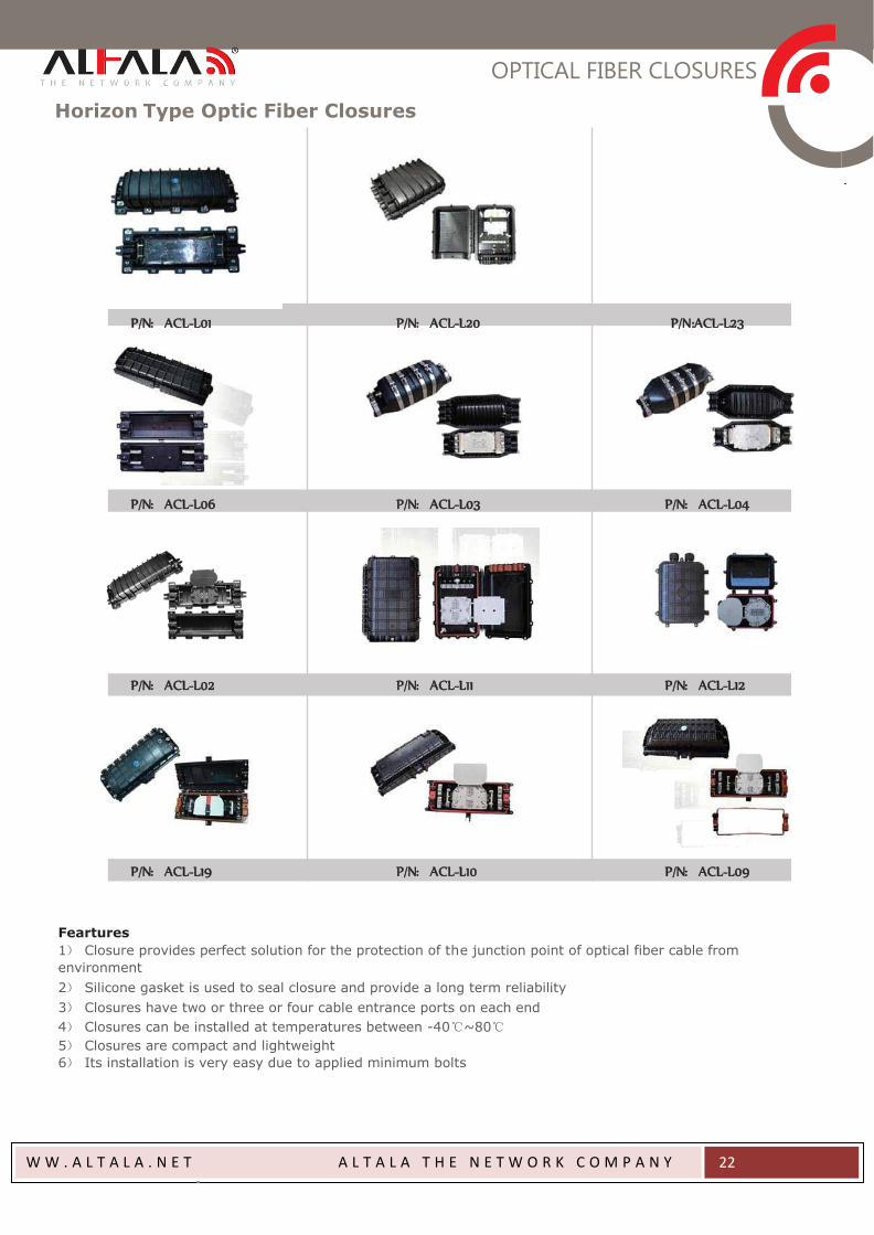
Horizon Type Optic Fiber Closures
P/N:ACL-L01 P/N:ACL-L20 P/N:ACL-L23
P/N:ACL-L06 P/N:ACL-L03 P/N:ACL-L04
P/N:ACL-L02 P/N:ACL-L11 P/N:ACL-L12
P/N:ACL-L19 P/N:ACL-L10 P/N:ACL-L09
Feartures
1) Closure provides perfect solution for the protection of the junction point of optical fiber cable from
environment
2) Silicone gasket is used to seal closure and provide a long term reliability
3) Closures have two or three or four cable entrance ports on each end
4) Closures can be installed at temperatures between -40℃~80℃
5) Closures are compact and lightweight
6) Its installation is very easy due to applied minimum bolts
OPTICAL FIBER CLOSURES
W W . A L T A L A . N E T A L T A L A T H E N E T W O R K C O M P A N Y
23
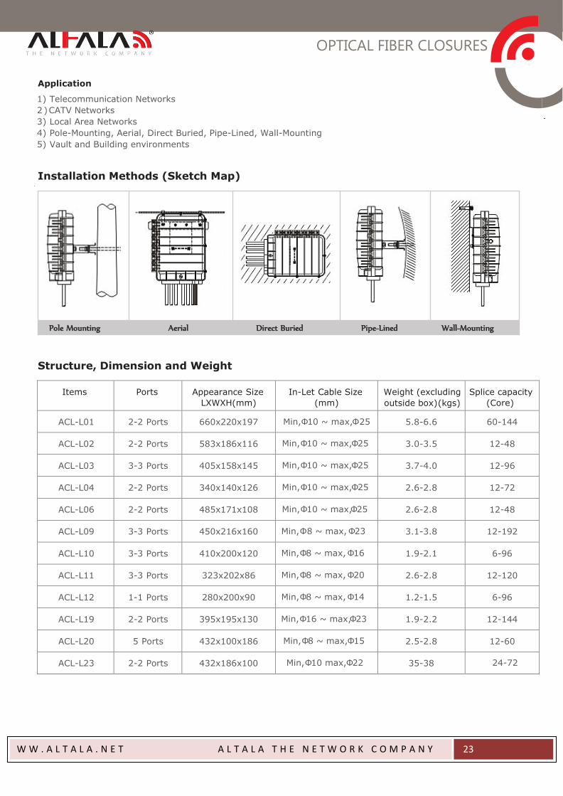
Application
1) Telecommunication Networks
2 ) CATV Networks
3) Local Area Networks
4) Pole-Mounting, Aerial, Direct Buried, Pipe-Lined, Wall-Mounting
5) Vault and Building environments
Installation Methods (Sketch Map)
Pole Mounting Aerial Direct Buried Pipe-Lined Wall-Mounting
Structure, Dimension and Weight
Items
Ports
Appearance Size
LXWXH(mm)
In-Let Cable Size
(mm)
Weight (excluding
outside box)(kgs)
Splice capacity
(Core)
ACL-L01
2-2 Ports
660x220x197
Min,Φ10 ~ max,Φ25
5.8-6.6
60-144
ACL-L02
2-2 Ports
583x186x116
Min,Φ10 ~ max,Φ25
3.0-3.5
12-48
ACL-L03
3-3 Ports
405x158x145
Min,Φ10 ~ max,Φ25
3.7-4.0
12-96
ACL-L04
2-2 Ports
340x140x126
Min,Φ10 ~ max,Φ25
2.6-2.8
12-72
ACL-L06
2-2 Ports
485x171x108
Min,Φ10 ~ max,Φ25
2.6-2.8
12-48
ACL-L09
3-3 Ports
450x216x160
Min,Φ8 ~ max, Φ23
3.1-3.8
12-192
ACL-L10
3-3 Ports
410x200x120
Min,Φ8 ~ max, Φ16
1.9-2.1
6-96
ACL-L11
3-3 Ports
323x202x86
Min,Φ8 ~ max, Φ20
2.6-2.8
12-120
ACL-L12
1-1 Ports
280x200x90
Min,Φ8 ~ max, Φ14
1.2-1.5
6-96
ACL-L19
2-2 Ports
395x195x130
Min,Φ16 ~ max,Φ23
1.9-2.2
12-144
ACL-L20
5 Ports
432x100x186
Min,Φ8 ~ max,Φ15
2.5-2.8
12-60
ACL-L23
2-2 Ports
432x186x100
Min,Φ10 max,Φ22
35-38
24-72
OPTICAL FIBER CLOSURES
W W . A L T A L A . N E T A L T A L A T H E N E T W O R K C O M P A N Y
24
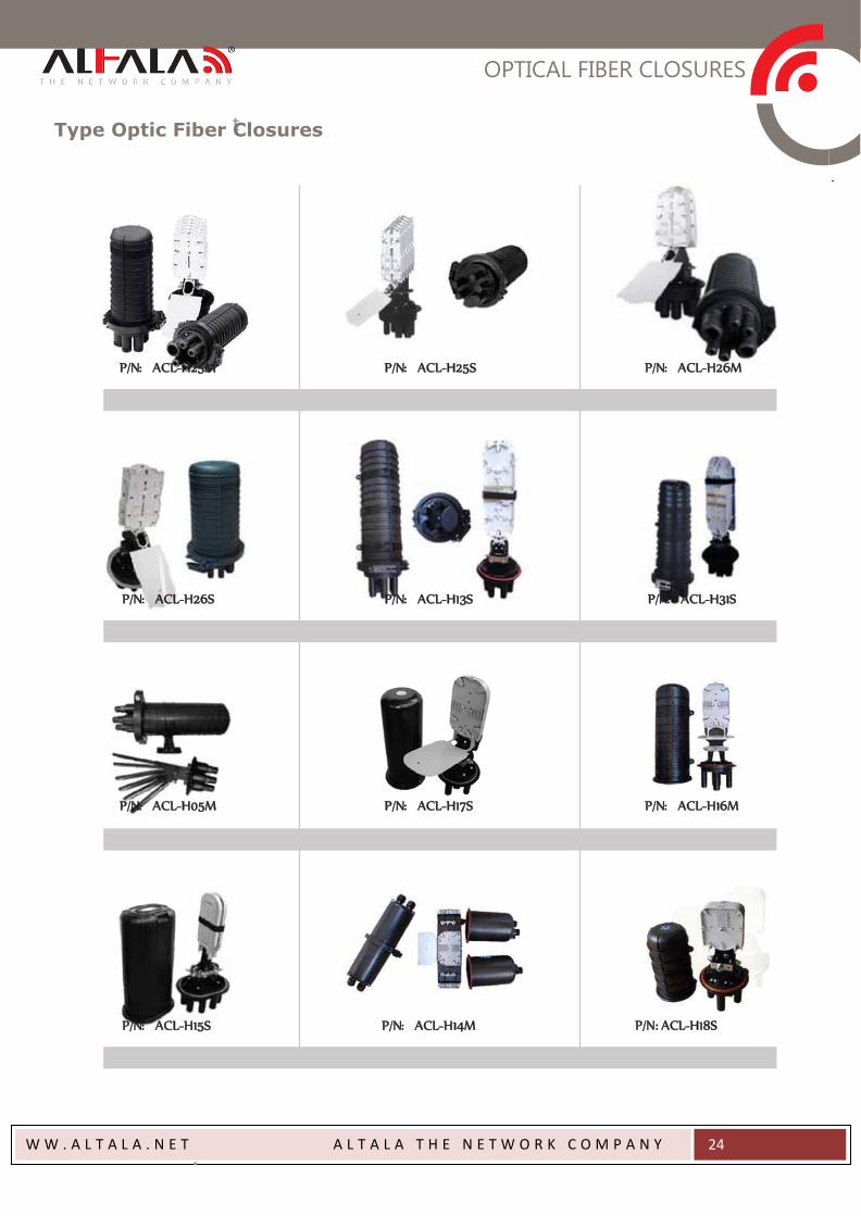
Type Optic Fiber Closures
P/N:ACL-H25M P/N:ACL-H25S P/N:ACL-H26M
P/N:ACL-H26S P/N:ACL-H13S P/N:ACL-H31S
P/N:ACL-H05M P/N:ACL-H17S P/N:ACL-H16M
P/N:ACL-H15S P/N:ACL-H14M P/N: ACL-H18S
OPTICAL FIBER CLOSURES
W W . A L T A L A . N E T A L T A L A T H E N E T W O R K C O M P A N Y
25
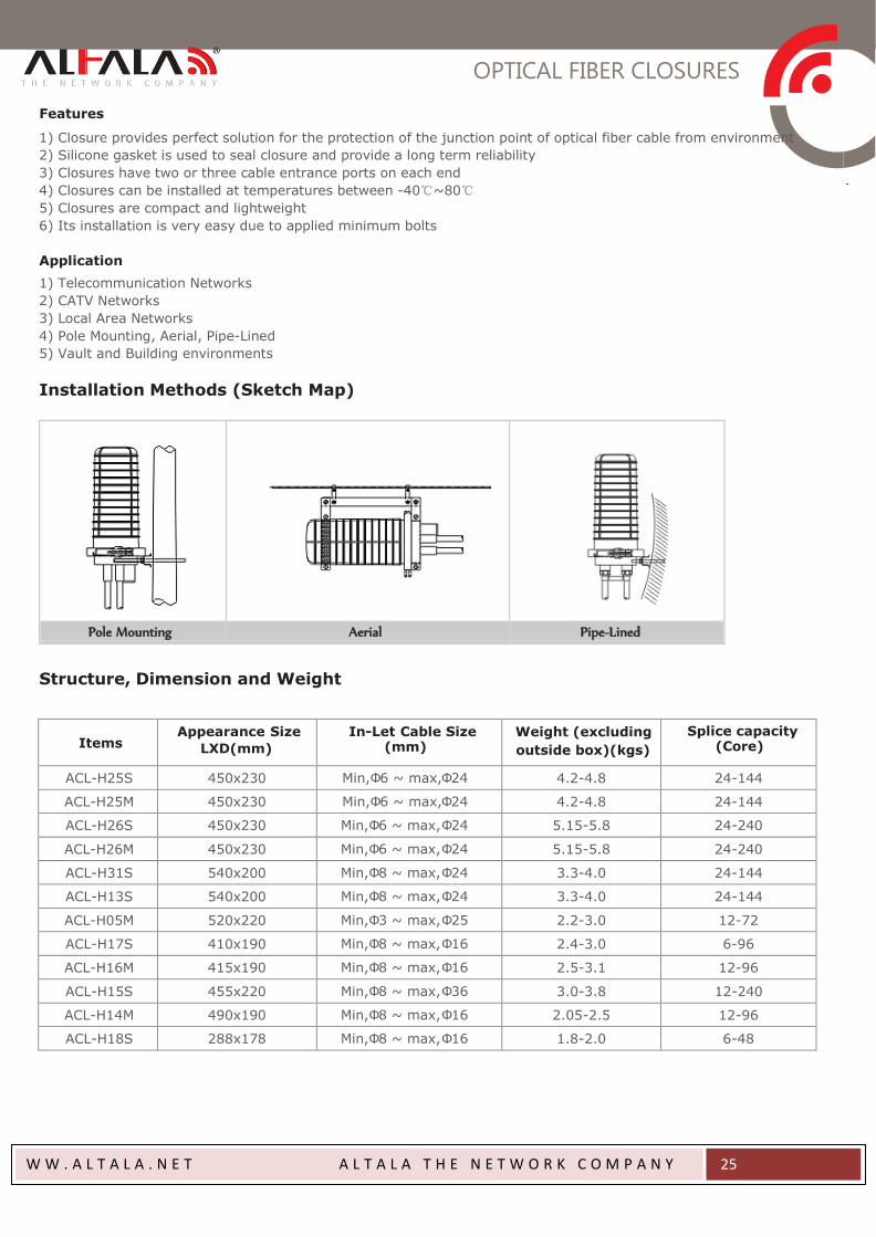
Features
1) Closure provides perfect solution for the protection of the junction point of optical fiber cable from environment
2) Silicone gasket is used to seal closure and provide a long term reliability
3) Closures have two or three cable entrance ports on each end
4) Closures can be installed at temperatures between -40℃~80℃
5) Closures are compact and lightweight
6) Its installation is very easy due to applied minimum bolts
Application
1) Telecommunication Networks
2) CATV Networks
3) Local Area Networks
4) Pole Mounting, Aerial, Pipe-Lined
5) Vault and Building environments
Installation Methods (Sketch Map)
Pole Mounting Aerial Pipe-Lined
Structure, Dimension and Weight
Items
Appearance Size
LXD(mm) In-Let Cable Size
(mm) Weight (excluding
outside box)(kgs) Splice capacity
(Core)
ACL-H25S 450x230 Min,Φ6 ~ max,Φ24 4.2-4.8 24-144
ACL-H25M 450x230 Min,Φ6 ~ max,Φ24 4.2-4.8 24-144
ACL-H26S 450x230 Min,Φ6 ~ max,Φ24 5.15-5.8 24-240
ACL-H26M 450x230 Min,Φ6 ~ max,Φ24 5.15-5.8 24-240
ACL-H31S 540x200 Min,Φ8 ~ max,Φ24 3.3-4.0 24-144
ACL-H13S 540x200 Min,Φ8 ~ max,Φ24 3.3-4.0 24-144
ACL-H05M 520x220 Min,Φ3 ~ max,Φ25 2.2-3.0 12-72
ACL-H17S 410x190 Min,Φ8 ~ max,Φ16 2.4-3.0 6-96
ACL-H16M 415x190 Min,Φ8 ~ max,Φ16 2.5-3.1 12-96
ACL-H15S 455x220 Min,Φ8 ~ max,Φ36 3.0-3.8 12-240
ACL-H14M 490x190 Min,Φ8 ~ max,Φ16 2.05-2.5 12-96
ACL-H18S 288x178 Min,Φ8 ~ max,Φ16 1.8-2.0 6-48
OPTICAL FIBER CLOSURES
W W . A L T A L A . N E T A L T A L A T H E N E T W O R K C O M P A N Y
26
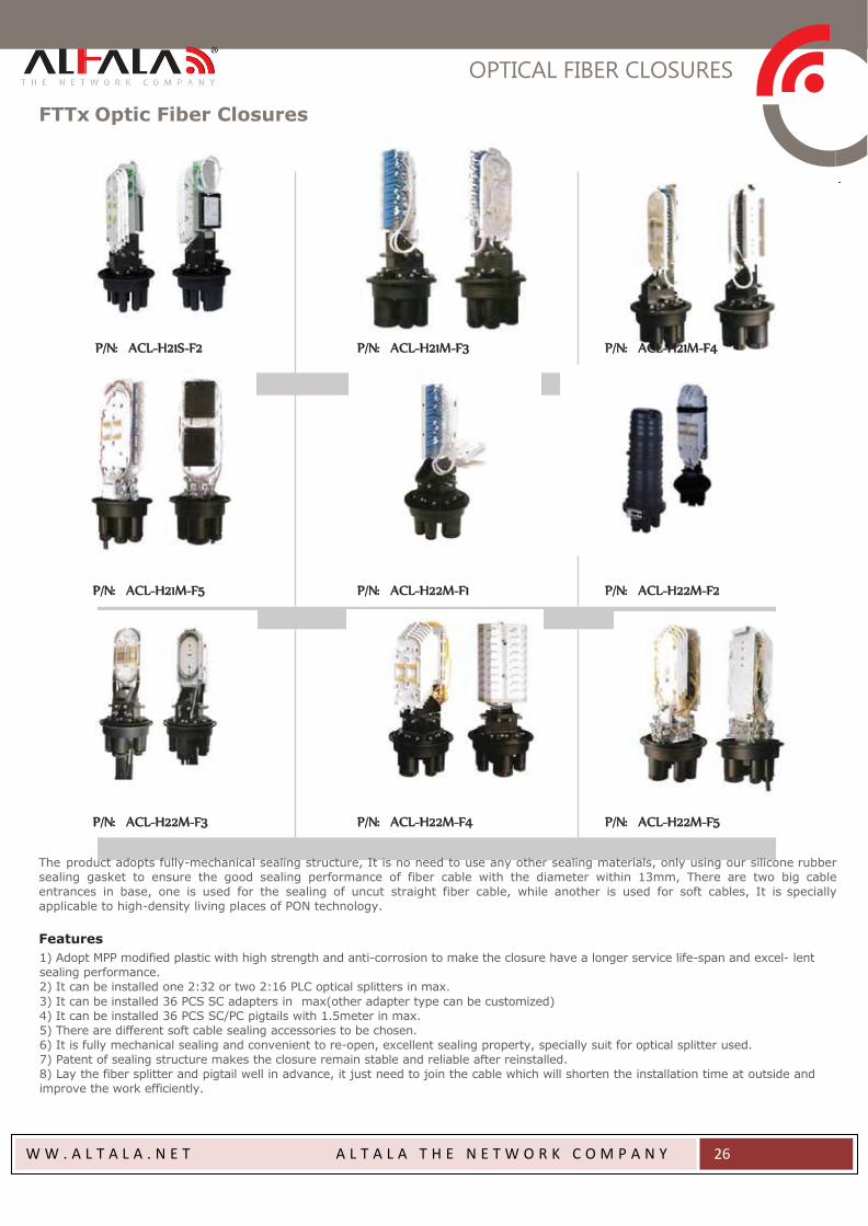
FTTx Optic Fiber Closures
P/N:ACL-H21S-F2 P/N:ACL-H21M-F3 P/N:ACL-H21M-F4
P/N:ACL-H21M-F5 P/N:ACL-H22M-F1 P/N:ACL-H22M-F2
P/N:ACL-H22M-F3 P/N:ACL-H22M-F4 P/N:ACL-H22M-F5
The product adopts fully-mechanical sealing structure, It is no need to use any other sealing materials, only using our silicone rubber
sealing gasket to ensure the good sealing performance of fiber cable with the diameter within 13mm, There are two big cable
entrances in base, one is used for the sealing of uncut straight fiber cable, while another is used for soft cables, It is specially
applicable to high-density living places of PON technology.
Features
1) Adopt MPP modified plastic with high strength and anti-corrosion to make the closure have a longer service life-span and excel- lent
sealing performance.
2) It can be installed one 2:32 or two 2:16 PLC optical splitters in max.
3) It can be installed 36 PCS SC adapters in max(other adapter type can be customized)
4) It can be installed 36 PCS SC/PC pigtails with 1.5meter in max.
5) There are different soft cable sealing accessories to be chosen.
6) It is fully mechanical sealing and convenient to re-open, excellent sealing property, specially suit for optical splitter used.
7) Patent of sealing structure makes the closure remain stable and reliable after reinstalled.
8) Lay the fiber splitter and pigtail well in advance, it just need to join the cable which will shorten the installation time at outside and
improve the work efficiently.
OPTICAL FIBER CLOSURES
W W . A L T A L A . N E T A L T A L A T H E N E T W O R K C O M P A N Y
27
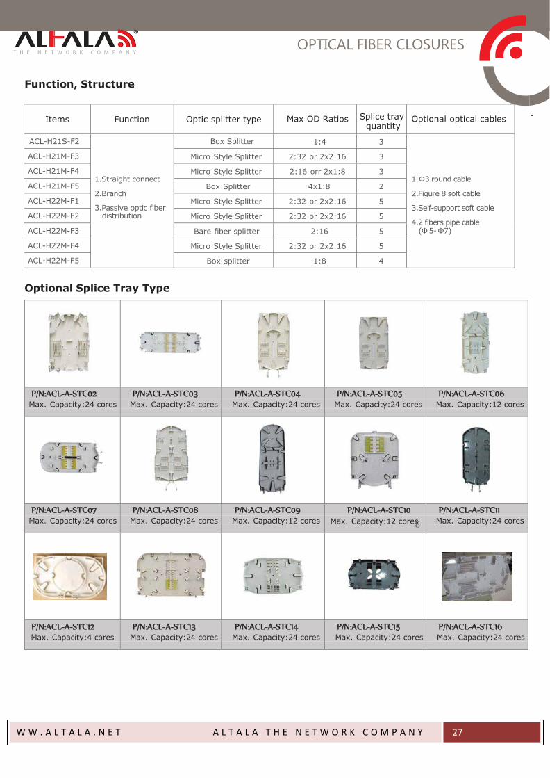
Function, Structure
Items
Function
Optic splitter type
Max OD Ratios
Splice tray quantity
Optional optical cables
ACL-H21S-F2
1.Straight connect
2.Branch
3.Passive optic fiber distribution
Box Splitter 1:4 3
1.Φ3 round cable
2.Figure 8 soft cable
3.Self-support soft cable
4.2 fibers pipe cable (Φ 5- Φ7)
ACL-H21M-F3 Micro Style Splitter 2:32 or 2x2:16 3
ACL-H21M-F4 Micro Style Splitter 2:16 orr 2x1:8 3
ACL-H21M-F5 Box Splitter 4x1:8 2
ACL-H22M-F1 Micro Style Splitter 2:32 or 2x2:16 5
ACL-H22M-F2 Micro Style Splitter 2:32 or 2x2:16 5
ACL-H22M-F3 Bare fiber splitter 2:16 5
ACL-H22M-F4 Micro Style Splitter 2:32 or 2x2:16 5
ACL-H22M-F5 Box splitter 1:8 4
Optional Splice Tray Type
P/N:ACL-A-STC02 Max. Capacity:24 cores
P/N:ACL-A-STC03 Max. Capacity:24 cores
P/N:ACL-A-STC04 Max. Capacity:24 cores
P/N:ACL-A-STC05 Max. Capacity:24 cores
P/N:ACL-A-STC06 Max. Capacity:12 cores
P/N:ACL-A-STC07 Max. Capacity:24 cores
P/N:ACL-A-STC08 Max. Capacity:24 cores
P/N:ACL-A-STC09 Max. Capacity:12 cores
P/N:ACL-A-STC10 Max. Capacity:12 cores8
P/N:ACL-A-STC11 Max. Capacity:24 cores
P/N:ACL-A-STC12 Max. Capacity:4 cores
P/N:ACL-A-STC13 Max. Capacity:24 cores
P/N:ACL-A-STC14 Max. Capacity:24 cores
P/N:ACL-A-STC15 Max. Capacity:24 cores
P/N:ACL-A-STC16 Max. Capacity:24 cores
OPTICAL FIBER CLOSURES
W W . A L T A L A . N E T A L T A L A T H E N E T W O R K C O M P A N Y
28
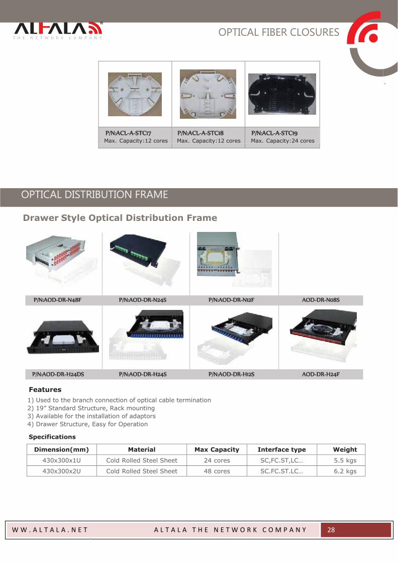
P/N:ACL-A-STC17 Max. Capacity:12 cores
P/N:ACL-A-STC18 Max. Capacity:12 cores
P/N:ACL-A-STC19 Max. Capacity:24 cores
OPTICAL DISTRIBUTION FRAME
Drawer Style Optical Distribution Frame
P/N:AOD-DR-N48F P/N:AOD-DR-N24S P/N:AOD-DR-N12F AOD-DR-N08S
P/N:AOD-DR-H24DS P/N:AOD-DR-H24S P/N:AOD-DR-H12S AOD-DR-H24F
Features
1) Used to the branch connection of optical cable termination
2) 19” Standard Structure, Rack mounting
3) Available for the installation of adaptors
4) Drawer Structure, Easy for Operation
Specifications
Dimension(mm) Material Max Capacity Interface type Weight
430x300x1U Cold Rolled Steel Sheet 24 cores SC,FC.ST,LC… 5.5 kgs
430x300x2U Cold Rolled Steel Sheet 48 cores SC.FC.ST.LC… 6.2 kgs
OPTICAL DISTRIBUTION FRAME
W W . A L T A L A . N E T A L T A L A T H E N E T W O R K C O M P A N Y
29
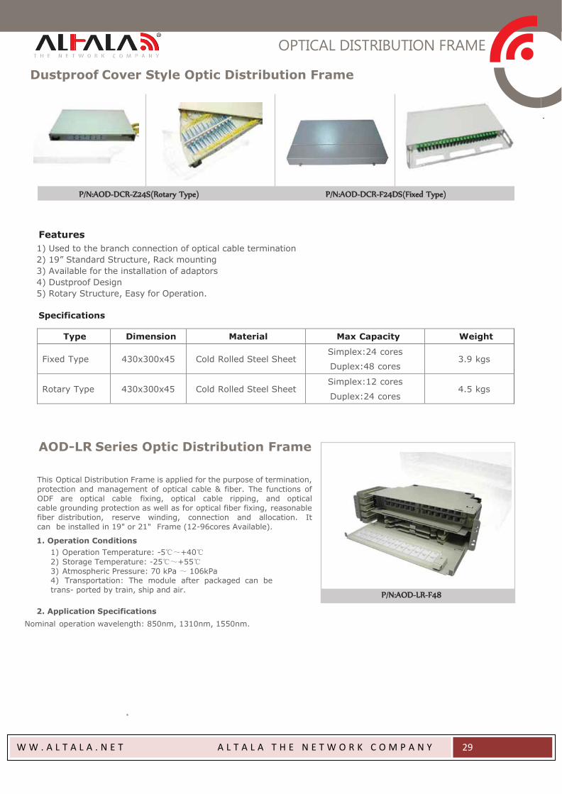
Dustproof Cover Style Optic Distribution Frame
P/N:AOD-DCR-Z24S(Rotary Type) P/N:AOD-DCR-F24DS(Fixed Type)
Features
1) Used to the branch connection of optical cable termination
2) 19” Standard Structure, Rack mounting
3) Available for the installation of adaptors
4) Dustproof Design
5) Rotary Structure, Easy for Operation.
Specifications
Type Dimension Material Max Capacity Weight Fixed Type
430x300x45
Cold Rolled Steel Sheet
Simplex:24 cores
Duplex:48 cores
3.9 kgs
Rotary Type
430x300x45
Cold Rolled Steel Sheet
Simplex:12 cores
Duplex:24 cores
4.5 kgs
AOD-LR Series Optic Distribution Frame
This Optical Distribution Frame is applied for the purpose of termination,
protection and management of optical cable & fiber. The functions of
ODF are optical cable fixing, optical cable ripping, and optical
cable grounding protection as well as for optical fiber fixing, reasonable
fiber distribution, reserve winding, connection and allocation. It
can be installed in 19" or 21" Frame (12-96cores Available).
1. Operation Conditions
1) Operation Temperature: -5℃~+40℃
2) Storage Temperature: -25℃~+55℃
3) Atmospheric Pressure: 70 kPa ~ 106kPa
4) Transportation: The module after packaged can be
trans- ported by train, ship and air.
2. Application Specifications
Nominal operation wavelength: 850nm, 1310nm, 1550nm.
P/N:AOD-LR-F48
OPTICAL DISTRIBUTION FRAME
W W . A L T A L A . N E T A L T A L A T H E N E T W O R K C O M P A N Y
30
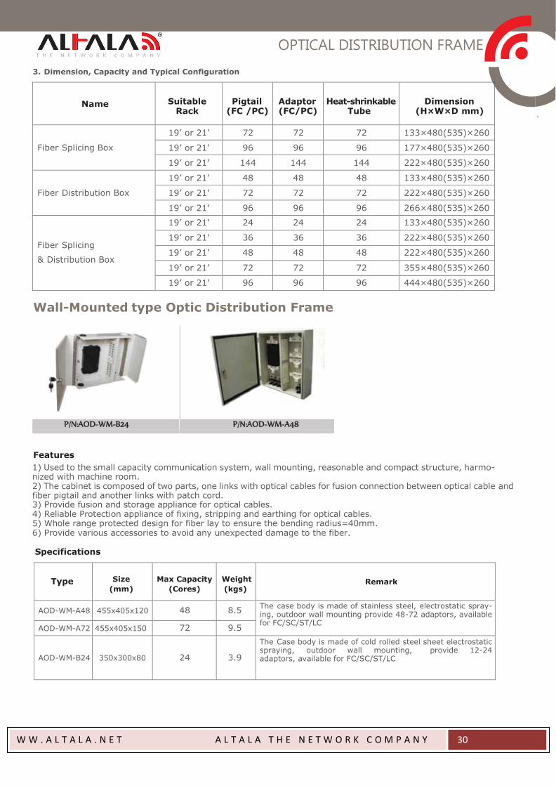
3. Dimension, Capacity and Typical Configuration
Name
Suitable
Rack
Pigtail
(FC /PC)
Adaptor (FC/PC)
Heat-shrinkable
Tube
Dimension
(H×W×D mm)
Fiber Splicing Box
19’ or 21’ 72 72 72 133×480(535)×260
19’ or 21’ 96 96 96 177×480(535)×260
19’ or 21’ 144 144 144 222×480(535)×260
Fiber Distribution Box
19’ or 21’ 48 48 48 133×480(535)×260
19’ or 21’ 72 72 72 222×480(535)×260
19’ or 21’ 96 96 96 266×480(535)×260
Fiber Splicing
& Distribution Box
19’ or 21’ 24 24 24 133×480(535)×260
19’ or 21’ 36 36 36 222×480(535)×260
19’ or 21’ 48 48 48 222×480(535)×260
19’ or 21’ 72 72 72 355×480(535)×260
19’ or 21’ 96 96 96 444×480(535)×260
Wall-Mounted type Optic Distribution Frame
P/N:AOD-WM-B24 P/N:AOD-WM-A48
Features
1) Used to the small capacity communication system, wall mounting, reasonable and compact structure, harmo- nized with machine room. 2) The cabinet is composed of two parts, one links with optical cables for fusion connection between optical cable and fiber pigtail and another links with patch cord. 3) Provide fusion and storage appliance for optical cables. 4) Reliable Protection appliance of fixing, stripping and earthing for optical cables. 5) Whole range protected design for fiber lay to ensure the bending radius=40mm. 6) Provide various accessories to avoid any unexpected damage to the fiber.
Specifications
Type
Size
(mm)
Max Capacity
(Cores)
Weight
(kgs)
Remark
AOD-WM-A48
455x405x120 48 8.5 The case body is made of stainless steel, electrostatic spray- ing, outdoor wall mounting provide 48-72 adaptors, available for FC/SC/ST/LC
AOD-WM-A72 455x405x150 72 9.5
AOD-WM-B24
350x300x80
24
3.9
The Case body is made of cold rolled steel sheet electrostatic spraying, outdoor wall mounting, provide 12-24 adaptors, available for FC/SC/ST/LC
OPTICAL DISTRIBUTION FRAME
W W . A L T A L A . N E T A L T A L A T H E N E T W O R K C O M P A N Y
31
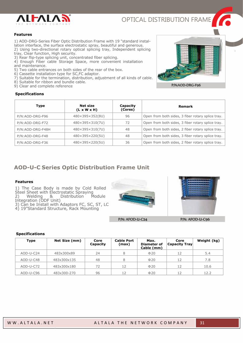
Features
1) AOD-DRG-Series Fiber Optic Distribution Frame with 19 "standard instal- lation interface, the surface electrostatic spray, beautiful and generous. 2) Using two-directional rotary optical splicing tray, Independent splicing tray, Clear function, High security. 3) Rear flip-type splicing unit, concentrated fiber splicing. 4) Enough Fiber cable Storage Space, more convenient installation and maintenance. 5) Two cable entrances on both sides of the rear of the box. 6) Cassette installation type for SC,FC adaptor. 7) Suitable for the termination, distribution, adjustment of all kinds of cable. 8) Suitable for ribbon and bundle cable. 9) Clear and complete reference
P/N:AOD-DRG-F96
Specifications
Type
Net size
(L x W x H)
Capacity (Cores)
Remark
P/N:AOD-DRG-F96 480×395×352(8U) 96 Open from both sides, 3 fiber rotary splice tray.
P/N:AOD-DRG-F72 480×395×310(7U) 72 Open from both sides, 3 fiber rotary splice tray.
P/N:AOD-DRG-F48H 480×395×310(7U) 48 Open from both sides, 2 fiber rotary splice tray.
P/N:AOD-DRG-F48 480×395×220(5U) 48 Open from both sides, 3 fiber rotary splice tray.
P/N:AOD-DRG-F36 480×395×220(5U) 36 Open from both sides, 2 fiber rotary splice tray.
AOD-U-C Series Optic Distribution Frame Unit
Features
1) The Case Body is made by Cold Rolled Steel Sheet with Electrostatic Spraying 2) Welding & Distribution Module Integration (ODF Unit) 3) Can be Install with Adaptors FC, SC, ST, LC 4) 19”Standard Structure, Rack Mounting
P/N: AFOD-U-C24 P/N: AFOD-U-C96
Specifications
Type Net Size (mm) Core Capacity
Cable Port (max)
Max. Diameter of Cable (mm)
Core Capacity Tray
Weight (kg)
AOD-U-C24 483x300x89 24 8 Ф 20 12 5.4
AOD-U-C48
483x300x135
48
8
Ф 20
12
7.8
AOD-U-C72
483x300x180
72
12
Ф 20
12
10.6
AOD-U-C96
483x300-270
96
12
Ф 20
12
12.2
OPTICAL DISTRIBUTION FRAME
W W . A L T A L A . N E T A L T A L A T H E N E T W O R K C O M P A N Y
32
Packing Information
Type Net Size
(mm) Inner Carton Dimension
/Weight Outer Carton Dimension
/Weight No./Carton
(pcs)
AOD-U-C24
AOD-U-C48
483x300x89
483x300x135
582x360x126mm/5.6kg
582x360x171mm/8.1kg
585x365x630mm/31kg
585x365x685mm/31kg
5
4
AOD-U-C72 483x300x180 582x360x216mm/11kg 585x365x650mm/30.5kg 3
AOD-U-C96 483x300-270 582x360x306mm/12.6kg 585x365x615mm/26.5kg 2
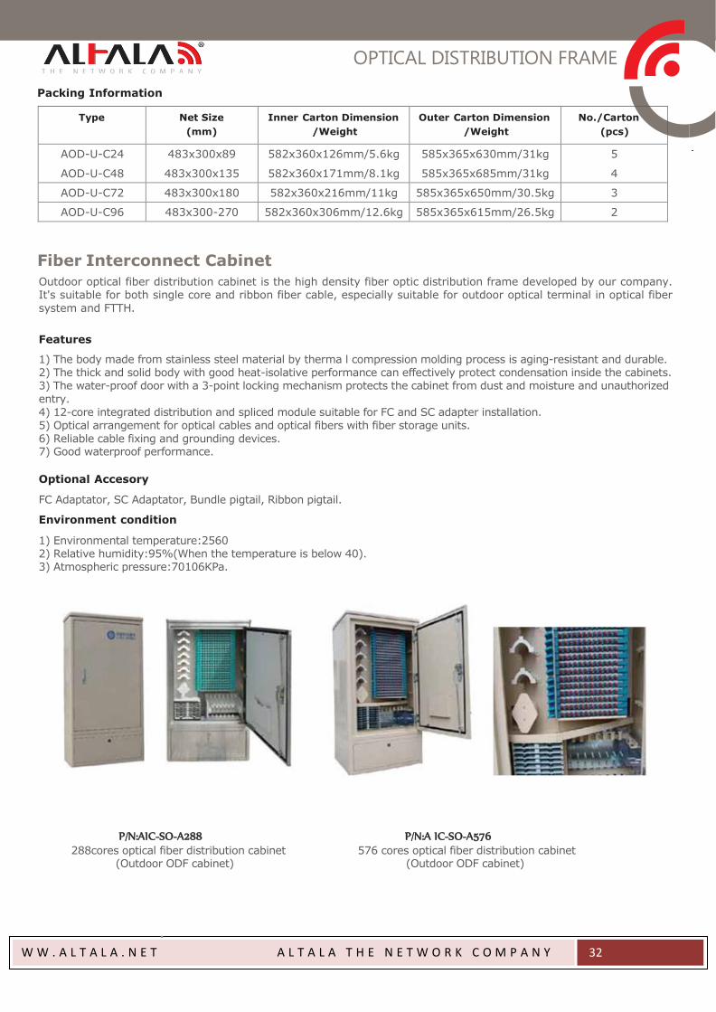
Fiber Interconnect Cabinet
Outdoor optical fiber distribution cabinet is the high density fiber optic distribution frame developed by our company. It's suitable for both single core and ribbon fiber cable, especially suitable for outdoor optical terminal in optical fiber
system and FTTH.
Features
1) The body made from stainless steel material by therma l compression molding process is aging-resistant and durable. 2) The thick and solid body with good heat-isolative performance can effectively protect condensation inside the cabinets. 3) The water-proof door with a 3-point locking mechanism protects the cabinet from dust and moisture and unauthorized
entry.
4) 12-core integrated distribution and spliced module suitable for FC and SC adapter installation. 5) Optical arrangement for optical cables and optical fibers with fiber storage units.
6) Reliable cable fixing and grounding devices. 7) Good waterproof performance.
Optional Accesory
FC Adaptator, SC Adaptator, Bundle pigtail, Ribbon pigtail.
Environment condition
1) Environmental temperature:2560 2) Relative humidity:95%(When the temperature is below 40). 3) Atmospheric pressure:70106KPa.
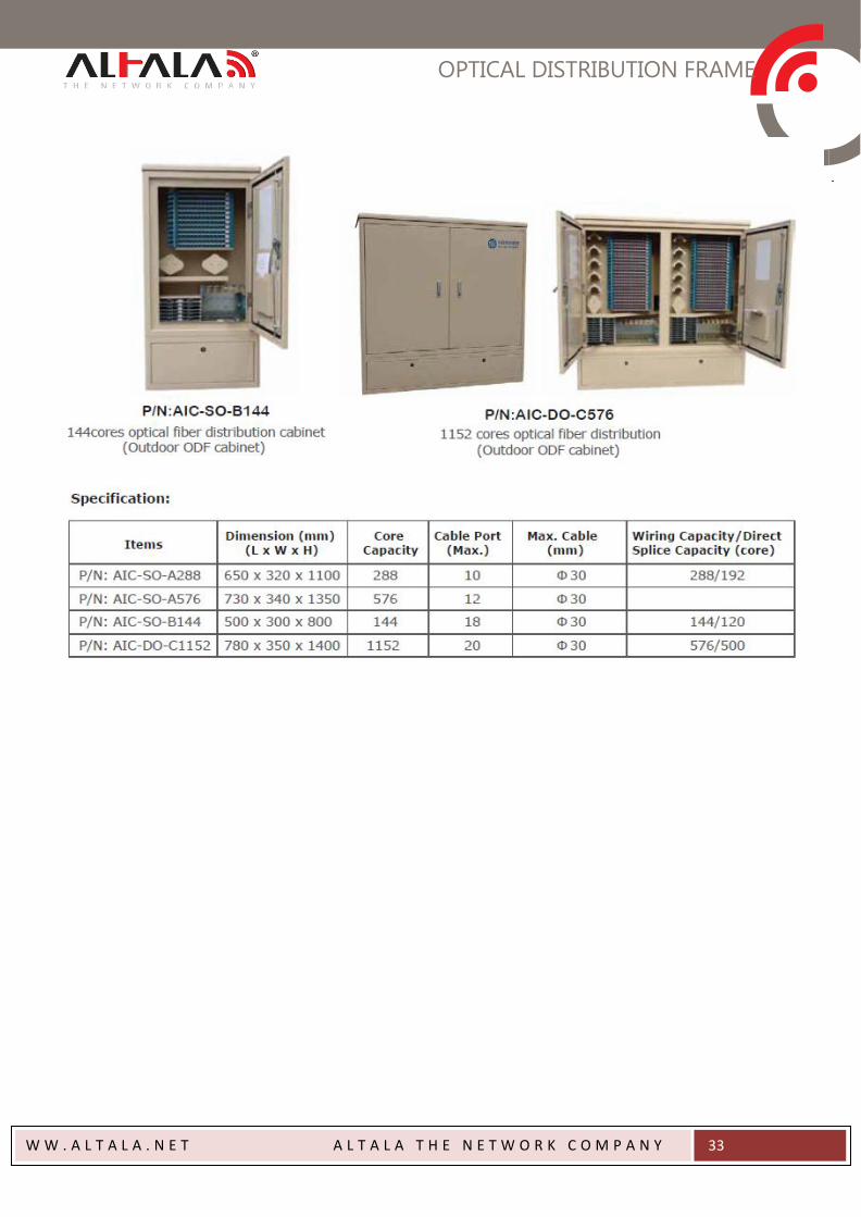
P/N:AIC-SO-A288 288cores optical fiber distribution cabinet
(Outdoor ODF cabinet)
P/N:A IC-SO-A576 576 cores optical fiber distribution cabinet
(Outdoor ODF cabinet)
OPTICAL DISTRIBUTION FRAME
W W . A L T A L A . N E T A L T A L A T H E N E T W O R K C O M P A N Y
33
FIBER OPTIC TERMINAL BOX
W W . A L T A L A . N E T A L T A L A T H E N E T W O R K C O M P A N Y
34
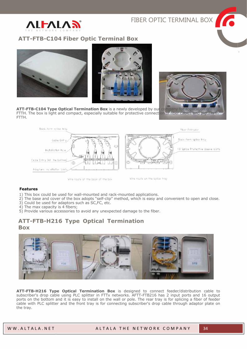
ATT-FTB-C104 Fiber Optic Terminal Box
ATT-FTB-C104 Type Optical Termination Box is a newly developed by our company for application of FTTH. The box is light and compact, especially suitable for protective connection of fiber cables and pigtails in FTTH.
Features
1) This box could be used for wall-mounted and rack-mounted applications. 2) The base and cover of the box adopts “self-clip” method, which is easy and convenient to open and close. 3) Could be used for adaptors such as SC,FC, etc. 4) The max capacity is 4 fibers; 5) Provide various accessories to avoid any unexpected damage to the fiber.
ATT-FTB-H216 Type Optical Termination Box
ATT-FTB-H216 Type Optical Termination Box is designed to connect feeder/distribution cable to subscriber's drop cable using PLC splitter in FTTx networks. AFTT-FTB216 has 2 input ports and 16 output ports on the bottom and it is easy to install on the wall or pole. The rear tray is for splicing a fiber of feeder cable with PLC splitter and the front tray is for connecting subscriber's drop cable through adaptor plate on the tray.

FIBER OPTIC TERMINAL BOX
W W . A L T A L A . N E T A L T A L A T H E N E T W O R K C O M P A N Y
35
Features
1) User familiar industry interface, using high impact plastic 2) Can accommodate 1x8 PLC splitter and 1x16 PLC splitter 3) Ultra violet resistant and rainfall resistant 4) Up to 16 FTTH drops 5) Wall and pole mountable 6) inlet ports, 16 outlet ports
Specifications
ITEM Values Dimensions L : 225 ㎜ , W : 302 ㎜ , H : 71 ㎜ Weight 1.3 ㎏ Cable input port Max. 2 ports (Max. dia. : 12 ㎜)
Cable output capacity Max. 16 ports (Max. dia. : 3 ㎜)
Max. capacity 12 core Operation Temperature -40 ~ +85
OTB Resin
Tensile Strength ≥ 450 ㎏/㎠ , @10 ㎜/min
Impact Strength 35 ㎏㎝ /㎠ (normal temp.), 10 ㎏㎝ /㎠ (-30)
Flexural Strength ≥ 450 ㎏/㎠ , @10 ㎜/min
Other Type Fiber Optic Terminal Box
P/N:ATB-C102
1) This box could be used for wall-
mounted and rack-mounted applica-
tions;
2) The base and cover of the box
adopts "self-clip" method, which is
easy and convenient to open and dose;
3) Could be used for adaptors such as
SC.FC etc.
4) The max capacity is 2 fibers.
P/N:ATT-TB104
H140 x W130 x
D36
(mm)
1) Applied to connect and storage
between pigtails and cables in the
building;
2) Reliable fixing and peeling for fiber
optic cables, open peel;
3) Small size, unique structure, easy
to install.
P/N:ATT-TB108
H200 x W165 x
D40 (mm)
1) Applied to connect and storage
between pigtails and cables in the
building;
2) Reliable fixing and peeling for fiber
optic cables, open peel;
3) Small size, unique structure, easy
to install.
FIBER OPTIC TERMINAL BOX
W W . A L T A L A . N E T A L T A L A T H E N E T W O R K C O M P A N Y
36
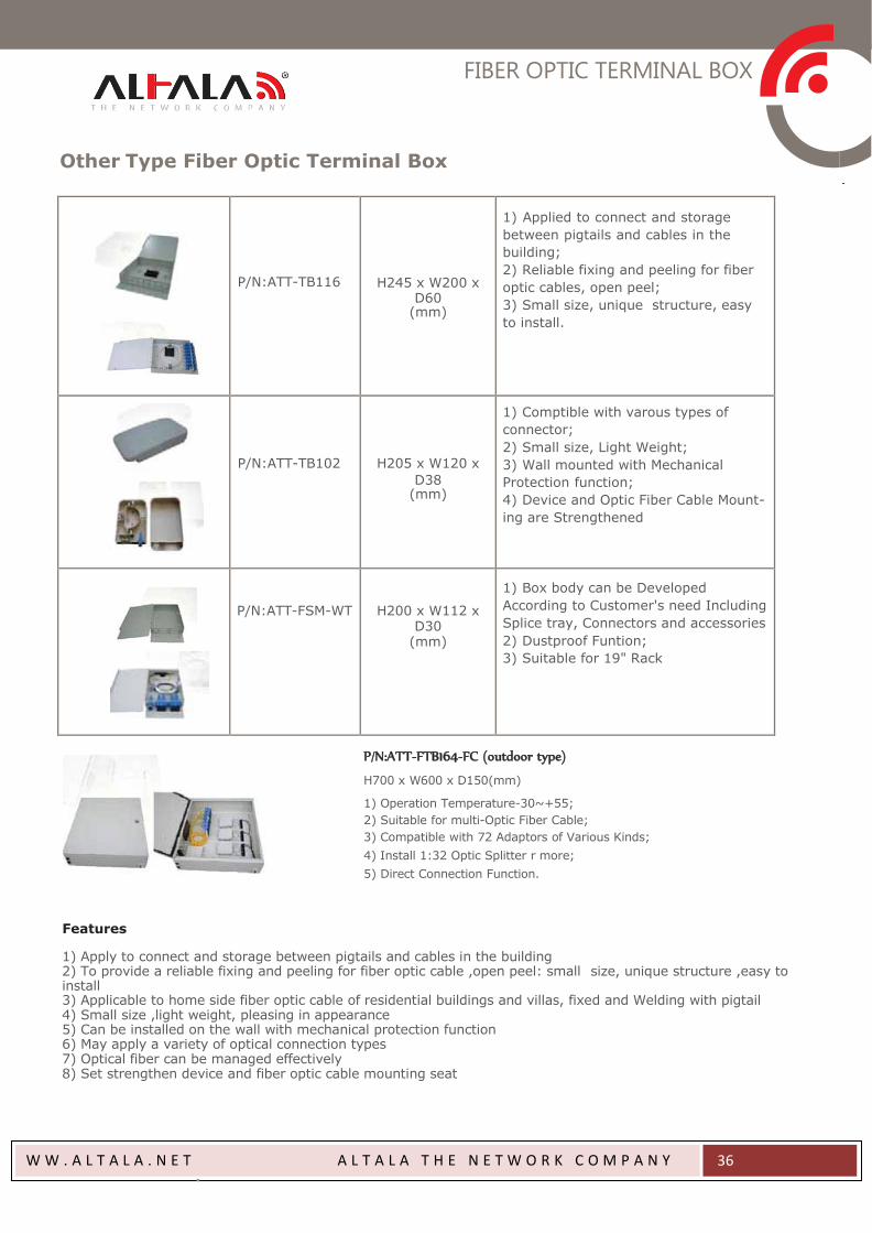
P/N:ATT-TB116
H245 x W200 x
D60 (mm)
1) Applied to connect and storage
between pigtails and cables in the
building;
2) Reliable fixing and peeling for fiber
optic cables, open peel;
3) Small size, unique structure, easy
to install.
P/N:ATT-TB102
H205 x W120 x
D38 (mm)
1) Comptible with varous types of
connector;
2) Small size, Light Weight;
3) Wall mounted with Mechanical
Protection function;
4) Device and Optic Fiber Cable Mount-
ing are Strengthened
P/N:ATT-FSM-WT
H200 x W112 x
D30 (mm)
1) Box body can be Developed
According to Customer's need Including
Splice tray, Connectors and accessories
2) Dustproof Funtion;
3) Suitable for 19" Rack
Other Type Fiber Optic Terminal Box
Features
P/N:ATT-FTB164-FC (outdoor type)
H700 x W600 x D150(mm)
1) Operation Temperature-30~+55;
2) Suitable for multi-Optic Fiber Cable;
3) Compatible with 72 Adaptors of Various Kinds;
4) Install 1:32 Optic Splitter r more;
5) Direct Connection Function.
1) Apply to connect and storage between pigtails and cables in the building 2) To provide a reliable fixing and peeling for fiber optic cable ,open peel: small size, unique structure ,easy to install 3) Applicable to home side fiber optic cable of residential buildings and villas, fixed and Welding with pigtail 4) Small size ,light weight, pleasing in appearance 5) Can be installed on the wall with mechanical protection function 6) May apply a variety of optical connection types 7) Optical fiber can be managed effectively 8) Set strengthen device and fiber optic cable mounting seat
OPTIC FIBER SPLITTER
W W . A L T A L A . N E T A L T A L A T H E N E T W O R K C O M P A N Y
37
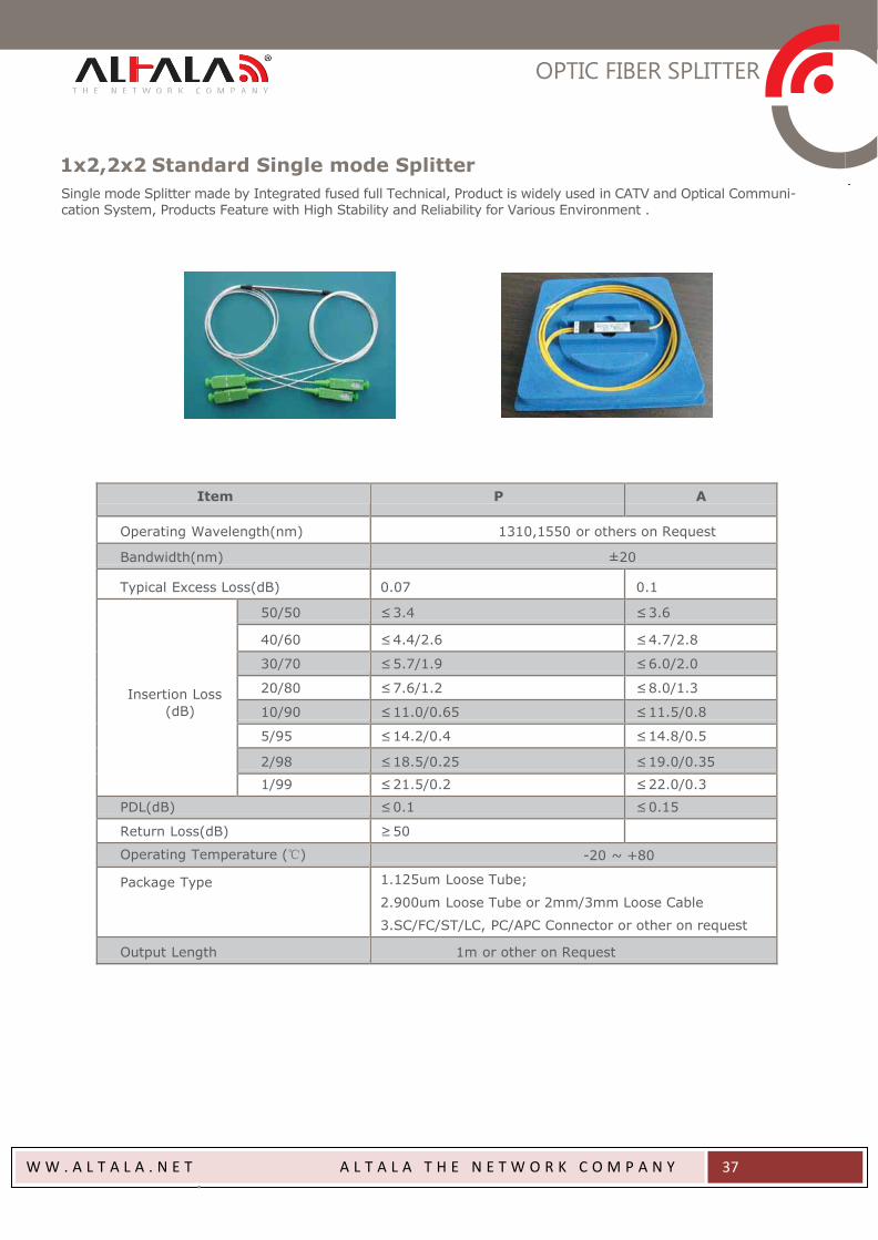
1x2,2x2 Standard Single mode Splitter
Single mode Splitter made by Integrated fused full Technical, Product is widely used in CATV and Optical Communi-
cation System, Products Feature with High Stability and Reliability for Various Environment .
Item P A
Operating Wavelength(nm) 1310,1550 or others on Request
Bandwidth(nm) ±20
Typical Excess Loss(dB)
0.07
0.1
Insertion Loss
(dB)
50/50 ≤ 3.4 ≤ 3.6
40/60 ≤ 4.4/2.6 ≤ 4.7/2.8
30/70 ≤ 5.7/1.9 ≤ 6.0/2.0
20/80 ≤ 7.6/1.2 ≤ 8.0/1.3
10/90 ≤ 11.0/0.65 ≤ 11.5/0.8
5/95 ≤ 14.2/0.4 ≤ 14.8/0.5
2/98 ≤ 18.5/0.25 ≤ 19.0/0.35
1/99 ≤ 21.5/0.2 ≤ 22.0/0.3
PDL(dB) ≤ 0.1 ≤ 0.15
Return Loss(dB) ≥ 50
Operating Temperature (℃) -20 ~ +80
Package Type 1.125um Loose Tube;
2.900um Loose Tube or 2mm/3mm Loose Cable
3.SC/FC/ST/LC, PC/APC Connector or other on request
Output Length 1m or other on Request
OPTIC FIBER SPLITTER
W W . A L T A L A . N E T A L T A L A T H E N E T W O R K C O M P A N Y
38
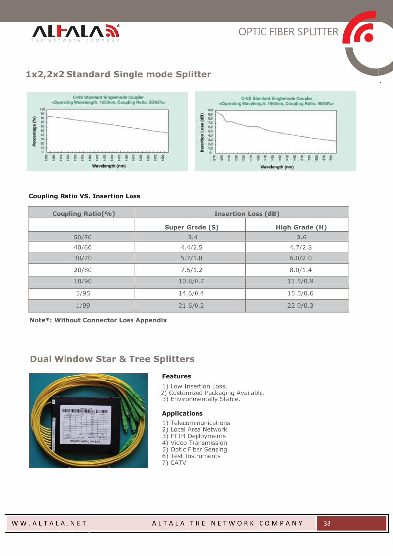
1x2,2x2 Standard Single mode Splitter
Coupling Ratio VS. Insertion Loss
Coupling Ratio(%) Insertion Loss (dB)
Super Grade (S)
High Grade (H)
50/50 3.4 3.6
40/60 4.4/2.5 4.7/2.8
30/70 5.7/1.8 6.0/2.0
20/80 7.5/1.2 8.0/1.4
10/90 10.8/0.7 11.5/0.9
5/95 14.6/0.4 15.5/0.6
1/99 21.6/0.2 22.0/0.3
Note*: Without Connector Loss Appendix
Dual Window Star & Tree Splitters
Features
1) Low Insertion Loss. 2) Customized Packaging Available. 3) Environmentally Stable.
Applications
1) Telecommunications 2) Local Area Network 3) FTTH Deployments 4) Video Transmission 5) Optic Fiber Sensing 6) Test Instruments 7) CATV

OPTIC FIBER SPLITTER
W W . A L T A L A . N E T A L T A L A T H E N E T W O R K C O M P A N Y
39
Specification for Dual Window Star Splitter
Item Dual Window Star Splitters
Port Configuration 4x4 8x8 16x16 32x32
Operating 1310 ±40 and 1550 ±40
Wavelength(nm)
Grade H A H A H A H A
Max. Insertion Loss(dB) 7.2 7.6 10.8 11.7 14.5 15.5 18.5 20.0
Uniformity(dB) 1.0 1.4 2.1 3.2 2.7 4.0 3.0 6.0
Operating Temperature(℃) -40 ~ +85
Storage Temperature(℃) -55 ~ +85
Note*:0 ℃ ~ +70 ℃ for 900um, 2.0mm,3.0mm Cable
Specification for Dual Window Tree Splitter
Item Dual Window Tree Splitters
Port Configuration 1(2)x4 1(2)x8 1(2)x16 1(2)x32
Operating 1310 ±40 and 1550 ±40
Wavelength(nm)
Grade H A H A H A H A
Max. Insertion Loss(dB) 7.2 7.6 10.0 11.7 14.5 15.5 18.5 20.0
Uniformity(dB) 0.9 1.4 2.1 3.2 2.6 4.0 3.0 6.0
Operating Temperature(℃) -40 ~ +85
Storage Temperature(℃) -55 ~ +85
Note*:1. 0 ℃ ~ +70 ℃ for 900um, 2.0mm,3.0mm Cable
2. Insertion Loss: Without Connector Loss.
Unitary 1x3/1x4 Dual Window Wideband Splitters
Features
1) Low Insertion Loss. 2) High Uniformity 3) Customized Packaging Available. 4) Environmentally Stable.
Applications
1) Telecommunications 2) Local Area Network 3) FTTH Deployments 4) Video Transmission 5) Optic Fiber Sensing 6) Test Instruments
OPTIC FIBER SPLITTER
W W . A L T A L A . N E T A L T A L A T H E N E T W O R K C O M P A N Y
40
Specifications
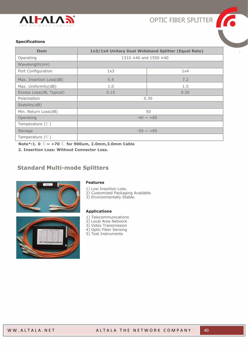
Item 1x3/1x4 Unitary Dual Wideband Splitter (Equal Rato)
Operating 1310 ±40 and 1550 ±40
Wavelength(nm)
Port Configuration 1x3 1x4
Max. Insertion Loss(dB) 5.4 7.2
Max. Uniformity(dB) 1.0 1.5
Excess Loss(dB, Typical) 0.15 0.30
Polarization 0.30
Stability(dB)
Min. Return Loss(dB) 50
Operating -40 ~ +85
Temperature (℃ )
Storage -55 ~ +85
Temperature (℃ )
Note*:1. 0 ℃ ~ +70 ℃ for 900um, 2.0mm,3.0mm Cable
2. Insertion Loss: Without Connector Loss.
Standard Multi-mode Splitters
Features
1) Low Insertion Loss. 2) Customized Packaging Available. 3) Environmentally Stable.
Applications
1) Telecommunications 2) Local Area Network 3) Video Transmission 4) Optic Fiber Sensing 5) Test Instruments
OPTIC FIBER SPLITTER
W W . A L T A L A . N E T A L T A L A T H E N E T W O R K C O M P A N Y
41
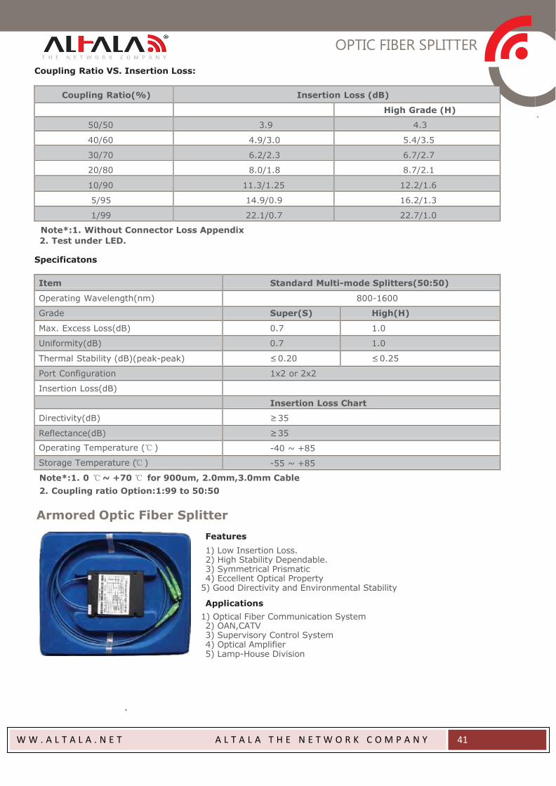
Coupling Ratio VS. Insertion Loss:
Coupling Ratio(%) Insertion Loss (dB)
High Grade (H)
50/50 3.9 4.3
40/60 4.9/3.0 5.4/3.5
30/70 6.2/2.3 6.7/2.7
20/80 8.0/1.8 8.7/2.1
10/90 11.3/1.25 12.2/1.6
5/95 14.9/0.9 16.2/1.3
1/99 22.1/0.7 22.7/1.0
Note*:1. Without Connector Loss Appendix
2. Test under LED.
Specificatons
Item Standard Multi-mode Splitters(50:50)
Operating Wavelength(nm) 800-1600
Grade Super(S) High(H)
Max. Excess Loss(dB) 0.7 1.0
Uniformity(dB) 0.7 1.0
Thermal Stability (dB)(peak-peak) ≤ 0.20 ≤ 0.25
Port Configuration 1x2 or 2x2
Insertion Loss(dB)
Insertion Loss Chart
Directivity(dB) ≥ 35
Reflectance(dB) ≥ 35
Operating Temperature (℃ ) -40 ~ +85
Storage Temperature (℃ ) -55 ~ +85
Note*:1. 0 ℃ ~ +70 ℃ for 900um, 2.0mm,3.0mm Cable
2. Coupling ratio Option:1:99 to 50:50
Armored Optic Fiber Splitter
Features
1) Low Insertion Loss. 2) High Stability Dependable. 3) Symmetrical Prismatic 4) Eccellent Optical Property
5) Good Directivity and Environmental Stability
Applications
1) Optical Fiber Communication System 2) OAN,CATV 3) Supervisory Control System 4) Optical Amplifier 5) Lamp-House Division

OPTIC FIBER SPLITTER
W W . A L T A L A . N E T A L T A L A T H E N E T W O R K C O M P A N Y
42
Specificatons
Parameter 1x4 1x8 1x16 1x32
Operating Wavelength (nm) 1260-1650
Insertion Loss (dB) Max 7.7 11.5 14.5 18.2
Homogeneity (dB) Min 0.8 1.0 1.4 1.9
Return Loss (dB) PC/UPC
Min(S/P)
45/55 45/55 45/55 45/55
50/55 50/55 50/55 50/55
Polarize Loss (dB) Max 0.3 0.3 0.3 0.3
Directivity (dB)
Max
55
55
55
55 Temperature Stability (-40 ~ 85 ℃) 0.5 0.5 0.5 0.5
Operating Temperature (℃) -40 ~ 85
19” Rack Type & Cupboard Type Optical Splitters
Features
1) Applicable for WDM. 2) Applicable for various kinds of optical coupler 3) Adaptor or Pigtail Output 4) Connectors: FC, SC, ST, LC, MU etc. 5) Polishing: PC, UPC, APC
1(2) x N PLC Splitters Planar Light-wave Circuit (PLC) splitter is a type of opical power management device that is fabricated using silica optical wave-
guide technology. It features small size, high reliability, wide oper- ating wavelength range and good channel-to-channel uniformity,
and is widely used in PON networks to realize optical signal power
splitting. We provides whole series of 1xN and 2xN splitter products
that are tailored for specific applications.
OPTIC FIBER SPLITTER
W W . A L T A L A . N E T A L T A L A T H E N E T W O R K C O M P A N Y
43
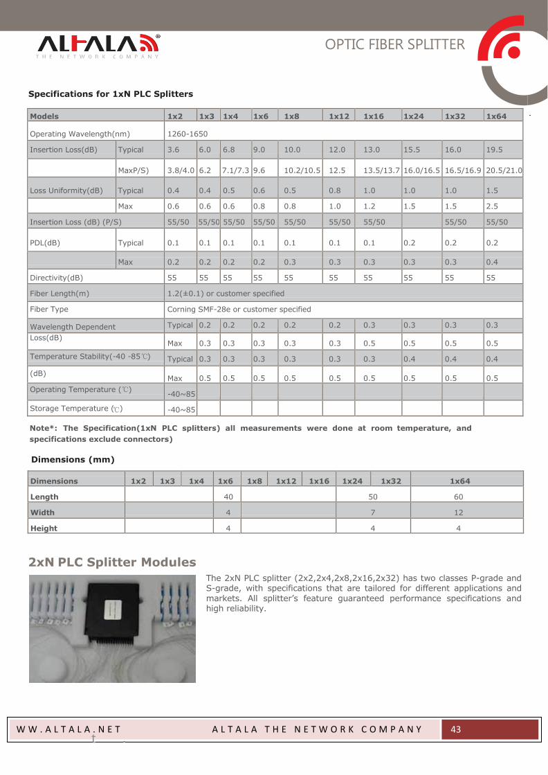
Specifications for 1xN PLC Splitters
Models 1x2 1x3 1x4 1x6 1x8 1x12 1x16 1x24 1x32 1x64
Operating Wavelength(nm)
1260-1650
Insertion Loss(dB) Typical 3.6 6.0 6.8 9.0 10.0 12.0 13.0 15.5 16.0 19.5
MaxP/S)
3.8/4.0
6.2
7.1/7.3
9.6
10.2/10.5
12.5
13.5/13.7
16.0/16.5
16.5/16.9
20.5/21.0
Loss Uniformity(dB)
Typical
0.4
0.4
0.5
0.6
0.5
0.8
1.0
1.0
1.0
1.5
Max 0.6 0.6 0.6 0.8 0.8 1.0 1.2 1.5 1.5 2.5
Insertion Loss (dB) (P/S) 55/50 55/50 55/50 55/50 55/50 55/50 55/50 55/50 55/50 PDL(dB)
Typical
0.1
0.1
0.1
0.1
0.1
0.1
0.1
0.2
0.2
0.2
Max
0.2
0.2
0.2
0.2
0.3
0.3
0.3
0.3
0.3
0.4
Directivity(dB) 55 55 55 55 55 55 55 55 55 55
Fiber Length(m) 1.2(±0.1) or customer specified
Fiber Type Corning SMF-28e or customer specified
Wavelength Dependent Typical 0.2 0.2 0.2 0.2 0.2 0.3 0.3 0.3 0.3
Loss(dB)
Max
0.3
0.3
0.3
0.3
0.3
0.5
0.5
0.5
0.5
Temperature Stability(-40 -85℃) Typical 0.3 0.3 0.3 0.3 0.3 0.3 0.4 0.4 0.4
(dB)
Max
0.5
0.5
0.5
0.5
0.5
0.5
0.5
0.5
0.5 Operating Temperature (℃)
-40~85
Storage Temperature (℃) -40~85
Note*: The Specification(1xN PLC splitters) all measurements were done at room temperature, and
specifications exclude connectors)
Dimensions (mm)
Dimensions
1x2
1x3
1x4
1x6
1x8
1x12
1x16
1x24
1x32
1x64
Length
40
50
60
Width
4
7
12
Height
4
4
4
2xN PLC Splitter Modules The 2xN PLC splitter (2x2,2x4,2x8,2x16,2x32) has two classes P-grade and S-grade, with specifications that are tailored for different applications and
markets. All splitter’s feature guaranteed performance specifications and high reliability.
OPTIC FIBER SPLITTER
W W . A L T A L A . N E T A L T A L A T H E N E T W O R K C O M P A N Y
44
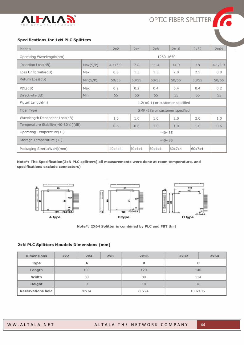
Specifications for 1xN PLC Splitters
Models 2x2 2x4 2x8 2x16 2x32 2x64
Operating Wavelength(nm) 1260-1650
Insertion Loss(dB)
Max(S/P)
4.1/3.9
7.8
11.4
14.9
18
4.1/3.9
Loss Uniformity(dB) Max 0.8 1.5 1.5 2.0 2.5 0.8
Return Loss(dB) Min(S/P) 50/55 50/55 50/55 50/55 50/55 50/55
PDL(dB)
Max
0.2
0.2
0.4
0.4
0.4
0.2
Directivity(dB) Min 55 55 55 55 55 55
Pigtail Length(m) 1.2(±0.1) or customer specified
Fiber Type SMF -28e or customer specified
Wavelength Dependent Loss(dB)
1.0
1.0
1.0
2.0
2.0
1.0
Temperature Stability(-40-80 ℃)(dB)
0.6
0.6
1.0
1.0
1.0
0.6
Operating Temperature(℃ ) -40~85
Storage Temperature (℃ ) -40~85
Packaging Size(LxWxH)(mm)
40x4x4
50x4x4
50x4x4
60x7x4
60x7x4
Note*: The Specification(2xN PLC splitters) all measurements were done at room temperature, and
specifications exclude connectors)
Note*: 2X64 Splitter is combined by PLC and FBT Unit
2xN PLC Splitters Moudels Dimensions (mm)
Dimensions 2x2 2x4 2x8 2x16 2x32 2x64
Type A B C
Length 100 120 140
Width 80 80 114
Height 9 18 18
Reservations hole 70x74 80x74 100x106
FIBER OPTIC PATCH CORD / PIGTAIL
W W . A L T A L A . N E T A L T A L A T H E N E T W O R K C O M P A N Y
45
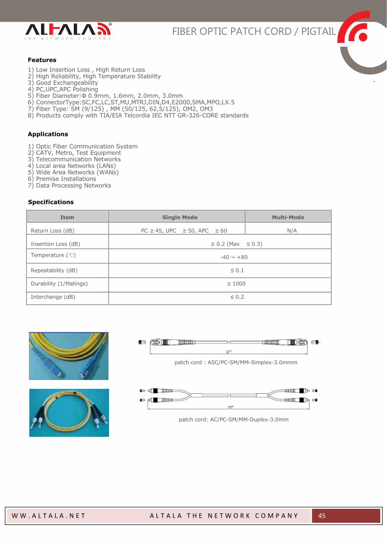
Features
1) Low Insertion Loss , High Return Loss 2) High Reliability, High Temperature Stability 3) Good Exchangeability 4) PC,UPC,APC Polishing 5) Fiber Diameter:Φ 0.9mm, 1.6mm, 2.0mm, 3.0mm 6) ConnectorType:SC,FC,LC,ST,MU,MTRJ,DIN,D4,E2000,SMA,MPO,LX.5 7) Fiber Type: SM (9/125) , MM (50/125, 62,5/125), OM2, OM3 8) Products comply with TIA/EIA Telcordia IEC NTT GR-326-CORE standards
Applications
1) Optic Fiber Communication System 2) CATV, Metro, Test Equipment 3) Telecommunication Networks 4) Local area Networks (LANs) 5) Wide Area Networks (WANs) 6) Premise Installations 7) Data Processing Networks
Specifications
Item
Single Mode
Multi-Mode
Return Loss (dB)
PC ≥ 45, UPC ≥ 50, APC ≥ 60
N/A
Insertion Loss (dB)
≤ 0.2 (Max ≤ 0.3)
Temperature (℃)
-40 ~ +80
Repeatability (dB)
≤ 0.1
Durability (1/Matings) ≥ 1000
Interchange (dB) ≤ 0.2
patch cord : ASC/PC-SM/MM-Simplex-3.0mmm
patch cord: AC/PC-SM/MM-Duplex-3.0mm

FIBER OPTIC PATCH CORD / PIGTAIL
W W . A L T A L A . N E T A L T A L A T H E N E T W O R K C O M P A N Y
46
Patch cord: AST/PC-SM-MM-Simplex-0.9mm/3.0mm
Patch cord: ALC/PC-SM/MM-Simplex-2.0mm
Patch cord: AMU/PC-SM/MM-Simplex-2.0mm
Patch cord: ADIN/PC-SM/MM-Simplex-3.0mm
Patch cord: AMTRJ/PC-SM/MM-Duplex-2.0mm
Patch cord: AD4/PC-SM/MM-Simplex-3.0mm
FIBER OPTIC PATCH CORD / PIGTAIL
W W . A L T A L A . N E T A L T A L A T H E N E T W O R K C O M P A N Y
47
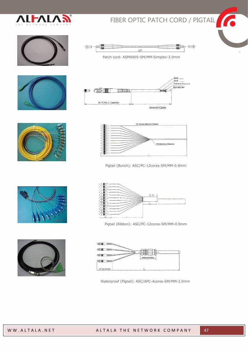
Patch cord: ASMA905-SM/MM-Simplex-3.0mm
Pigtail (Bunch): ASC/PC-12cores-SM/MM-0.9mm
Pigtail (Ribbon): ASC/PC-12cores-SM/MM-0.9mm
Waterproof (Pigtail): ASC/APC-4cores-SM/MM-2.0mm
FIBER OPTIC ADAPTATOR
W W . A L T A L A . N E T A L T A L A T H E N E T W O R K C O M P A N Y
48
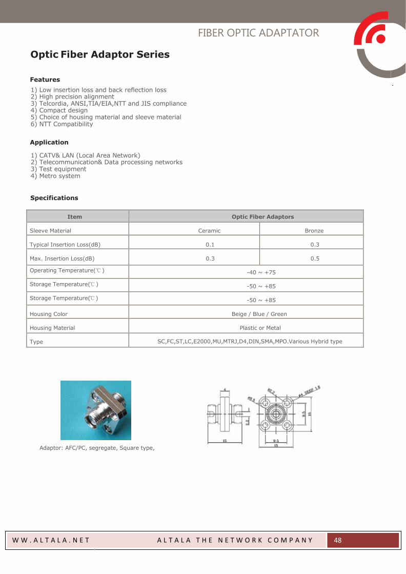
Optic Fiber Adaptor Series
Features
1) Low insertion loss and back reflection loss 2) High precision alignment 3) Telcordia, ANSI,TIA/EIA,NTT and JIS compliance 4) Compact design 5) Choice of housing material and sleeve material 6) NTT Compatibility
Application
1) CATV& LAN (Local Area Network) 2) Telecommunication& Data processing networks 3) Test equipment 4) Metro system
Specifications
Item Optic Fiber Adaptors
Sleeve Material
Ceramic
Bronze
Typical Insertion Loss(dB)
0.1
0.3
Max. Insertion Loss(dB)
0.3
0.5
Operating Temperature(℃ ) -40 ~ +75
Storage Temperature(℃ )
-50 ~ +85
Storage Temperature(℃ )
-50 ~ +85
Housing Color
Beige / Blue / Green
Housing Material
Plastic or Metal
Type
SC,FC,ST,LC,E2000,MU,MTRJ,D4,DIN,SMA,MPO.Various Hybrid type
Adaptor: AFC/PC, segregate, Square type,
FIBER OPTIC ADAPTATOR
W W . A L T A L A . N E T A L T A L A T H E N E T W O R K C O M P A N Y
49
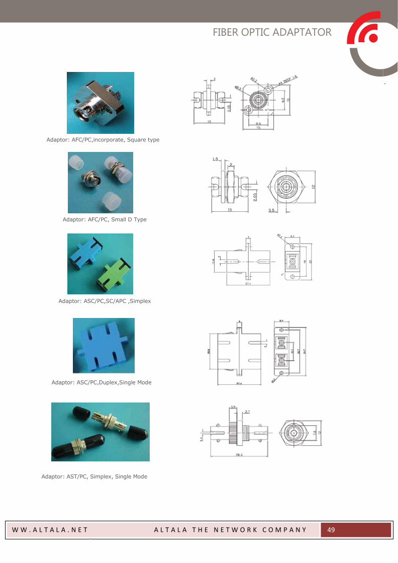
Adaptor: AFC/PC,incorporate, Square type
Adaptor: AFC/PC, Small D Type
Adaptor: ASC/PC,SC/APC ,Simplex
Adaptor: ASC/PC,Duplex,Single Mode
Adaptor: AST/PC, Simplex, Single Mode
FIBER OPTIC ADAPTATOR
W W . A L T A L A . N E T A L T A L A T H E N E T W O R K C O M P A N Y
50
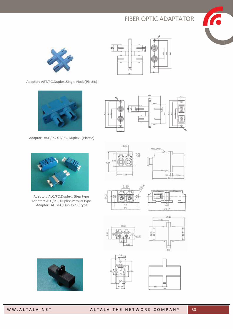
Adaptor: AST/PC,Duplex,Single Mode(Plastic)
Adaptor: ASC/PC-ST/PC, Duplex, (Plastic)
Adaptor: ALC/PC,Duplex, Step type
Adaptor: ALC/PC, Duplex,Parallel type
Adaptor: ALC/PC,Duplex SC type
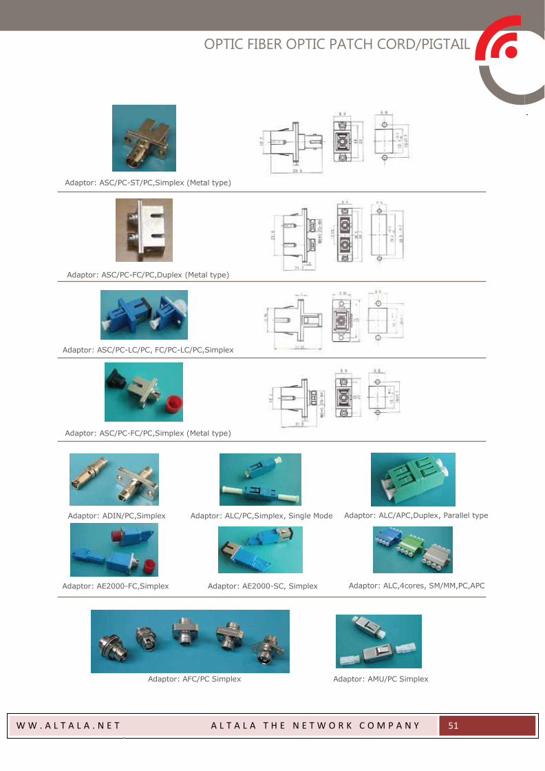
OPTIC FIBER OPTIC PATCH CORD/PIGTAIL
W W . A L T A L A . N E T A L T A L A T H E N E T W O R K C O M P A N Y
51
Adaptor: ASC/PC-ST/PC,Simplex (Metal type)
Adaptor: ASC/PC-FC/PC,Duplex (Metal type)
Adaptor: ASC/PC-LC/PC, FC/PC-LC/PC,Simplex
Adaptor: ASC/PC-FC/PC,Simplex (Metal type)
Adaptor: ADIN/PC,Simplex Adaptor: ALC/PC,Simplex, Single Mode Adaptor: ALC/APC,Duplex, Parallel type
Adaptor: AE2000-FC,Simplex Adaptor: AE2000-SC, Simplex Adaptor: ALC,4cores, SM/MM,PC,APC
Adaptor: AFC/PC Simplex Adaptor: AMU/PC Simplex
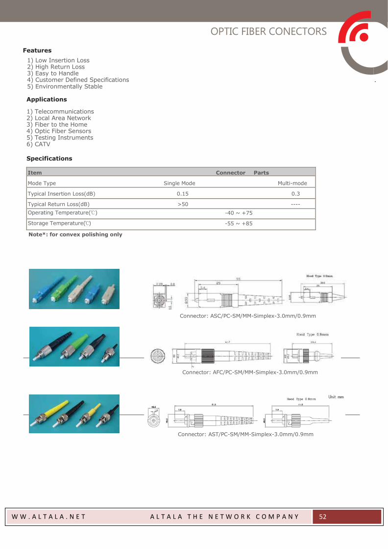
OPTIC FIBER CONECTORS
W W . A L T A L A . N E T A L T A L A T H E N E T W O R K C O M P A N Y
52
Features
1) Low Insertion Loss 2) High Return Loss 3) Easy to Handle 4) Customer Defined Specifications 5) Environmentally Stable
Applications
1) Telecommunications 2) Local Area Network 3) Fiber to the Home 4) Optic Fiber Sensors 5) Testing Instruments 6) CATV
Specifications
Item Connector Parts
Mode Type Single Mode Multi-mode
Typical Insertion Loss(dB) 0.15 0.3
Typical Return Loss(dB) >50 ---- Operating Temperature(℃) -40 ~ +75
Storage Temperature(℃) -55 ~ +85
Note*: for convex polishing only
Connector: ASC/PC-SM/MM-Simplex-3.0mm/0.9mm
Connector: AFC/PC-SM/MM-Simplex-3.0mm/0.9mm
Connector: AST/PC-SM/MM-Simplex-3.0mm/0.9mm
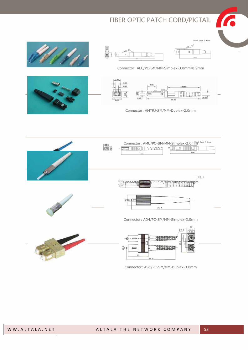
FIBER OPTIC PATCH CORD/PIGTAIL
W W . A L T A L A . N E T A L T A L A T H E N E T W O R K C O M P A N Y
53
Connector: ALC/PC-SM/MM-Simplex-3.0mm/0.9mm
Connector: AMTRJ-SM/MM-Duplex-2.0mm
Connector: AMU/PC-SM/MM-Simplex-2.0mm
Connector: ADIN/PC-SM/MM-Simplex-3.0mm
Connector: AD4/PC-SM/MM-Simplex-3.0mm
Connector: ASC/PC-SM/MM-Duplex-3.0mm
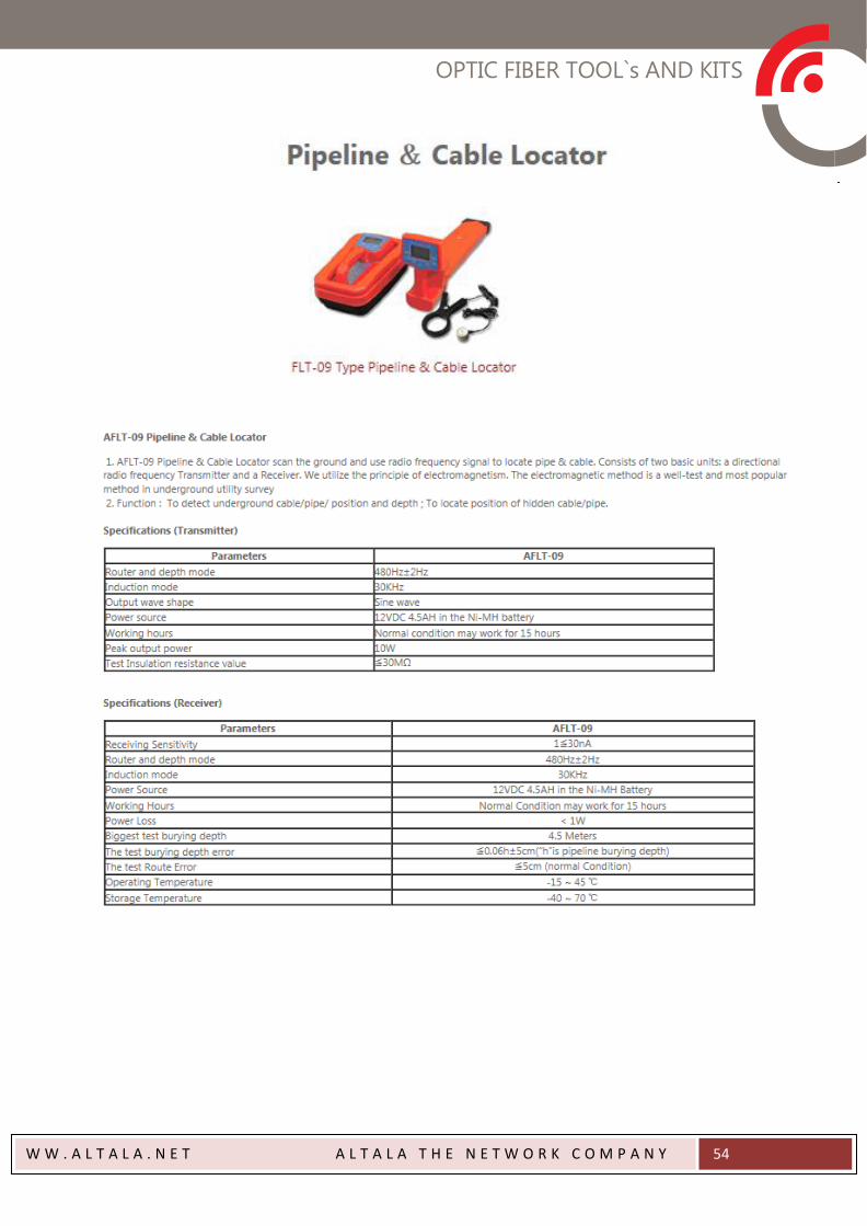
OPTIC FIBER TOOL`s AND KITS
W W . A L T A L A . N E T A L T A L A T H E N E T W O R K C O M P A N Y
54
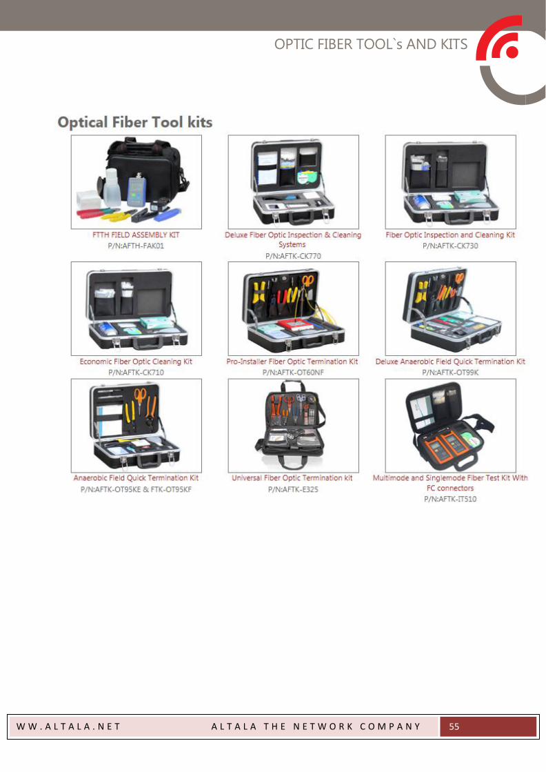
OPTIC FIBER TOOL`s AND KITS
W W . A L T A L A . N E T A L T A L A T H E N E T W O R K C O M P A N Y
55
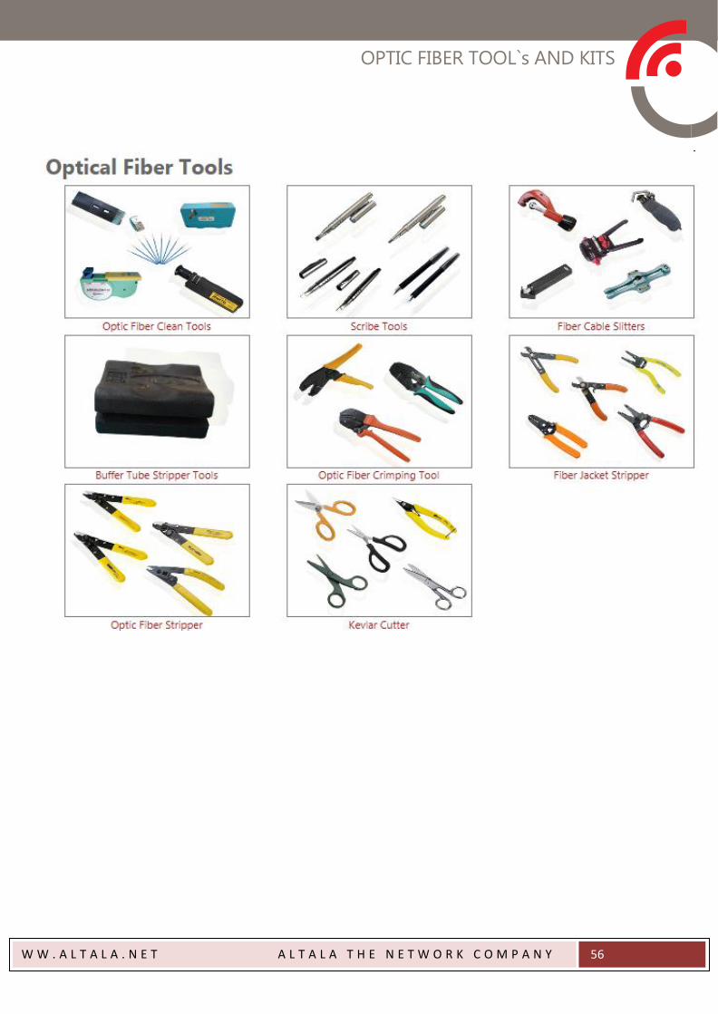
OPTIC FIBER TOOL`s AND KITS
W W . A L T A L A . N E T A L T A L A T H E N E T W O R K C O M P A N Y
56
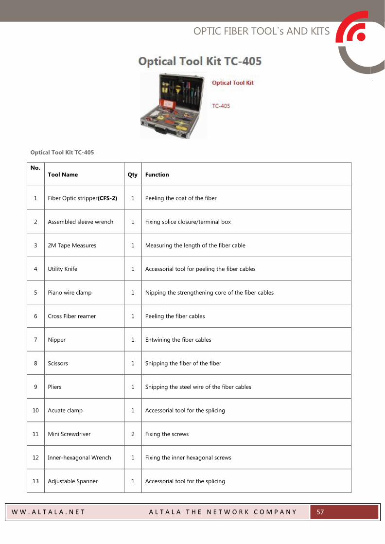
OPTIC FIBER TOOL`s AND KITS
W W . A L T A L A . N E T A L T A L A T H E N E T W O R K C O M P A N Y
57
Optical Tool Kit TC-405
No.
Tool Name Qty Function
1 Fiber Optic stripper(CFS-2) 1 Peeling the coat of the fiber
2 Assembled sleeve wrench 1 Fixing splice closure/terminal box
3 2M Tape Measures 1 Measuring the length of the fiber cable
4 Utility Knife 1 Accessorial tool for peeling the fiber cables
5 Piano wire clamp 1 Nipping the strengthening core of the fiber cables
6 Cross Fiber reamer 1 Peeling the fiber cables
7 Nipper 1 Entwining the fiber cables
8 Scissors 1 Snipping the fiber of the fiber
9 Pliers 1 Snipping the steel wire of the fiber cables
10 Acuate clamp 1 Accessorial tool for the splicing
11 Mini Screwdriver 2 Fixing the screws
12 Inner-hexagonal Wrench 1 Fixing the inner hexagonal screws
13 Adjustable Spanner 1 Accessorial tool for the splicing
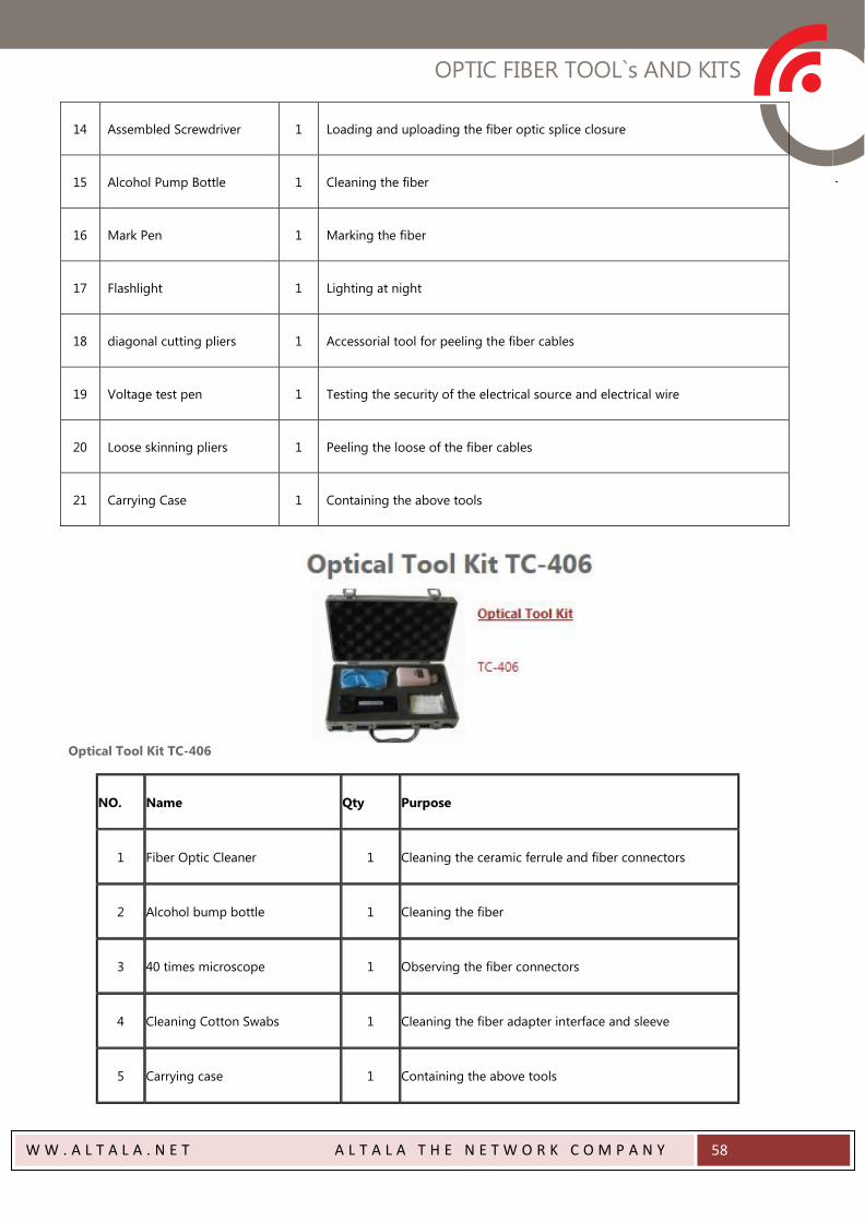
OPTIC FIBER TOOL`s AND KITS
W W . A L T A L A . N E T A L T A L A T H E N E T W O R K C O M P A N Y
58
14 Assembled Screwdriver 1 Loading and uploading the fiber optic splice closure
15 Alcohol Pump Bottle 1 Cleaning the fiber
16 Mark Pen 1 Marking the fiber
17 Flashlight 1 Lighting at night
18 diagonal cutting pliers 1 Accessorial tool for peeling the fiber cables
19 Voltage test pen 1 Testing the security of the electrical source and electrical wire
20 Loose skinning pliers 1 Peeling the loose of the fiber cables
21 Carrying Case 1 Containing the above tools
Optical Tool Kit TC-406
NO. Name Qty Purpose
1 Fiber Optic Cleaner 1 Cleaning the ceramic ferrule and fiber connectors
2 Alcohol bump bottle 1 Cleaning the fiber
3 40 times microscope 1 Observing the fiber connectors
4 Cleaning Cotton Swabs 1 Cleaning the fiber adapter interface and sleeve
5 Carrying case 1 Containing the above tools


ALTALA THE NETWORK COMPANY
Shyris N39281 y Gaspar de Villaroel Esq.
CC. La Galería Ofc. 28
Telf: 593 2 244 2082


