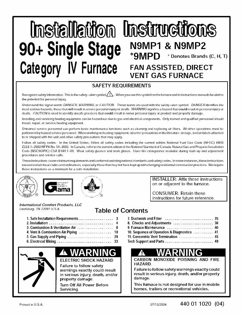
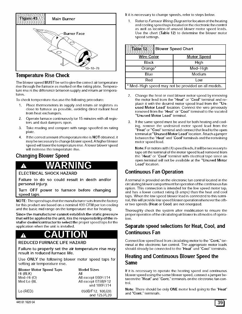
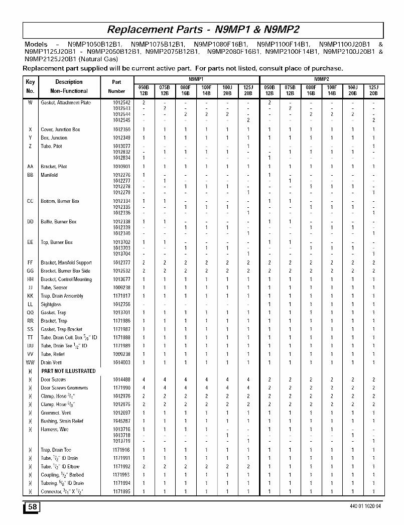
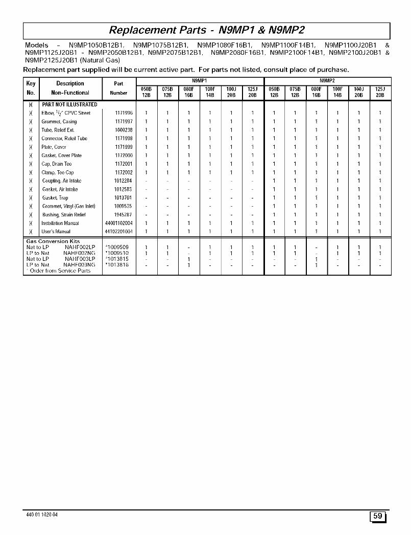
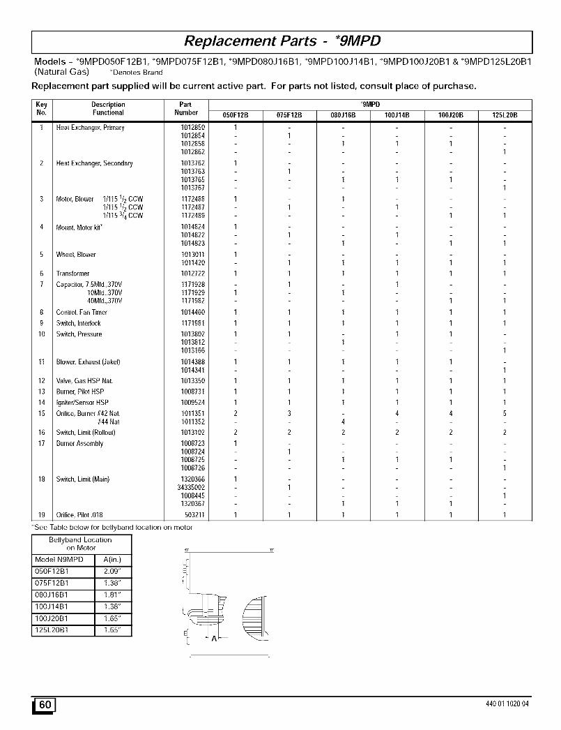
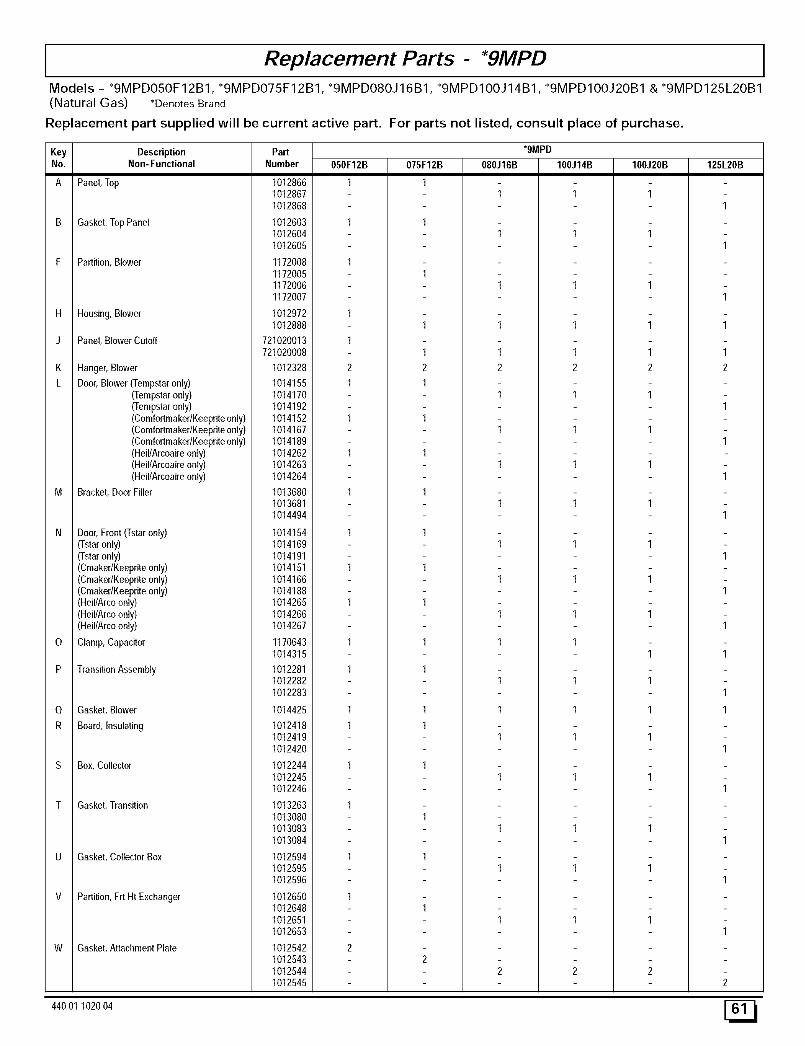
90 Single Stage Category IVFurnace N9MP1 & N9MP2 *9MPD *Denotes Brands (C, H, T) FAN ASSISTED, DIRECT VENT GAS FURNACE SAFETY REQUIREMENTS Recognize safety information. This is the safety- alert symbolZ.l_. When you see this symbol on the furnace and in instructions manuals be alert to the potential for personal injury. Understand the signal words DANGER, WARNING, or CAUTION. These words are used with the safety-alert symbol. DANGER identifies the most serious hazards, those that will result in severe personal injury or death. WARNING signifies a hazard that could result in personal injury or death. CAuT__Nis used t_ identify unsafe practices that c_u_d resu_t in min_r pers_na_ injury _r pr_duct and pr__erty damage. Installing and servicing heating equipment can be hazardous due to gas and electrical components. Only trained and qualified personnel should install, repair, or service heating equipment. Untrained service personnel can perform basic maintenance functions such as cleaning and replacing air filters. All other operations must be performed by trained service personnel. When working on heating equipment, observe precautions in the literature, on tags, and on labels attached to or shipped with the unit and other safety precautions that may apply. Follow all safety codes. In the United States, follow all safety codes including the current edition National Fuel Gas Code (NFGC) ANSI Z223.1-2002/NFPA No. 54-2002. In Canada, refer tothecurrent edition of the National Standard of Canada Natural Gas and Propane Installation Code (NSCNGPIC) CSA B149.1-00. Wear safety glasses and work gloves. Have fire extinguisher available during start-up and adjustment procedures and service calls. These instructions cover minimum requirements and conform to existing national standards and safety codes. In some instances, these instructions exceed certain local codes and ordinances, especially those that may not have kept up with changing residential construction practices. We require these instructions as a minimum for a safe installation. INSTALLER: Affix these instructions on or adjacent to the furnace. CONSUMER: Retain these instructions for future reference. International Comfort Products, LLC Lewisburg, TN 37091 U.S.A. Table of Contents 1. SafeInstallationRequirements ................. 3 2. Installation................................ 4 3. Combustion & Ventilation Air .................. 8 4.Vent & Combustion Air Piping ................ 10 5. GasSupply and Piping ...................... 29 6.ElectricalWiring ........................... 33 7. DuctworkandFilter ........................ 35 8. Checksand Adjustments.................... 38 9. FurnaceMaintenance ....................... 40 10.Sequenceof Operation& Diagnostics.......... 41 11. ConcentricVentTermination................. 45 TechSupport and Parts........................ 49 ELECTRIC SHOCK HAZARD Failure to follow safety warnings exactly could result in serious injury, death, and/or property damage. Turn Off All Power Before Servicing. CARBON MONOXIDE POISNING AND FIRE HAZARD. Failure to follow safety warnings exactly could result in serious injury, death, and/or property damage. This furnace is not designed for use in mobile homes, trailers or recreational vehicles. Printed inU.S.A. 07/15/2004 440 01 1020 (04)
Transcript
90 SingleStageCategoryIVFurnace
N9MP1 & N9MP2*9MPD *Denotes Brands (C, H, T)
FAN ASSISTED, DIRECTVENT GAS FURNACE
SAFETY REQUIREMENTS
Recognize safety information. This is the safety- alert symbolZ.l_. When you see this symbol on the furnace and in instructions manuals be alert to
the potential for personal injury.
Understand the signal words DANGER, WARNING, or CAUTION. These words are used with the safety-alert symbol. DANGER identifies the
most serious hazards, those that will result in severe personal injury or death. WARNING signifies a hazard that could result in personal injury or
death. CAuT__Nis used t_ identify unsafe practices that c_u_d resu_t in min_r pers_na_ injury _r pr_duct and pr__erty damage.
Installing and servicing heating equipment can be hazardous due to gas and electrical components. Only trained and qualified personnel should
install, repair, or service heating equipment.
Untrained service personnel can perform basic maintenance functions such as cleaning and replacing air filters. All other operations must be
performed by trained service personnel. When working on heating equipment, observe precautions in the literature, on tags, and on labels attached
to or shipped with the unit and other safety precautions that may apply.
Follow all safety codes. In the United States, follow all safety codes including the current edition National Fuel Gas Code (NFGC) ANSI
Z223.1-2002/NFPA No. 54-2002. In Canada, refer tothecurrent edition of the National Standard of Canada Natural Gas and Propane Installation
Code (NSCNGPIC) CSA B149.1-00. Wear safety glasses and work gloves. Have fire extinguisher available during start-up and adjustment
procedures and service calls.
These instructions cover minimum requirements and conform to existing national standards and safety codes. In some instances, these instructions
exceed certain local codes and ordinances, especially those that may not have kept up with changing residential construction practices. We require
these instructions as a minimum for a safe installation.
INSTALLER: Affix these instructionson or adjacent to the furnace.
CONSUMER: Retain theseinstructions for future reference.
International Comfort Products, LLCLewisburg, TN 37091 U.S.A. Table of Contents
Failure to follow safetywarnings exactly could resultin serious injury, death, and/orproperty damage.Turn Off All Power BeforeServicing.
CARBON MONOXIDE POISNING AND FIREHAZARD.
Failure to follow safety warnings exactly couldresult in serious injury, death, and/or propertydamage.
This furnace is not designed for use in mobilehomes, trailers or recreational vehicles.
PrintedinU.S.A. 07/15/2004 440 01 1020 (04)
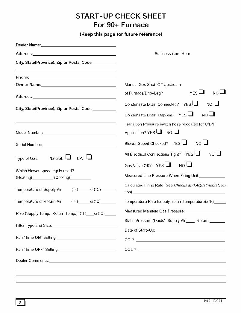
START-UP CHECK SHEET
For 90+ Furnace
(Keep this page for future reference)
Dealer Name:
Address:
City, State(Province), Zip or Postal Code:
Business Card Here
Phone:
Owner Name:
Address:
City, State(Province), Zip or Postal Code:
Model Number:
Serial Number:
Type of Gas: Natural: _ LP:
Which blower speed tap is used?
(Heating) (Cooling).
Temperature of Supply Air:
Temperature of Return Air:
(°F)___or(°C)
(°F) or(°C)__
Rise (Supply Temp.-Return Temp.): (°F) or(°C)__
Filter Type and Size:
Fan "Time ON" Setting:.
Fan "Time OFF" Setting:
Manual Gas Shut-Off Upstream
of Furnace/Drip- Leg?
Condensate Drain Connected?
YES
YES
Condensate Drain Trapped? YES
NOE_
NO
NO
Transition Pressure switch hose relocated for U/D/H
Application? YES _ NO
Blower Speed Checked? YES _ NO
All Electrical Connections Tight? YES _ NO
Gas Valve OK? YES _ NO
Measured Line Pressure When Firing Unit:
Calculated Firing Rate:(See Checks and Adjustments Sec-
tion).
Temperature Rise (supply-return temperature):(°F)__
Measured Manifold Gas Pressure:
Static Pressure (Ducts): Supply Air Return
Date of Start-Up:
CO?
CO2 ?
Dealer Comments:
E_ 44001102004
1. Safe Installation Requirements
FIRE, EXPLOSION, AND ASPHIXlATION HAZARD
Improper adjustment, alteration, service,maintanence or installation could cause seriousinjury, death and/or property damage.
Installation or repairs made by unqualified personscould result in hazards to you and others.Installation MUST conform with local codes or, inthe absence of local codes, with codes of allgovernmental authorities having,jurisdiction.The information contained in this manual isintended for use by a qualified service agency thatis experienced in such work, is familiar with allprecautions and safety procedures required insuch work, and is equipped with the proper toolsand test instruments.
NOTE: This furnace is design-certified by the CSA International
(formerly AGA and CGA) for installation in the United States andCanada. Refer to the appropriate codes, along with this manual,for proper installation.
• Use only the Type of gas approved for this furnace (see
Rating Plate on unit). Overfiring will result in failure of heatexchanger and cause dangerous operation. (Furnacescan be converted to L.P. gas with approved kit.)
• Install this furnace only in a location and position as speci-fied in "2. Installation"of these instructions.
• Provide adequate combustion and ventilation air to the fur-
nace as specified in "3. Combustion and Ventilation Air" ofthese instructions.
Combustion products must be discharged outdoors. Con-
nect this furnace to an approved vent system only, as spe-cified in "4. Vent and Combustion Air Piping" of theseinstructions.
Never test for gas leaks with an open flame. Use a com-mercially available soap solution made specifically for thedetection of leaks to check all connections, as specified in"6. Gas Supply and Piping, Final Check"of these instruc-tions.
Always install furnace to operate within the furnace's in-tended temperature-rise range with a duct system whichhas an external static pressure within the allowable range,as specified in "Technical Support Manual" of these in-structions.
• When a furnace is installed so that supply ducts carry aircirculated by the furnace to areas outside the space con-taining the furnace, the return air shall also be handled by aduct(s) sealed to the furnace casing and terminating out-side the space containing the furnace.
• A gas-fired furnace for installation in a residential garage
must be installed as specified in "2. Installation"of theseinstructions.
• This furnace is not to be used for temporary heating of
buildings or structures under construction.
• This furnace is NOT approved for installation in mo-bile homes, trailers or recreation vehicles.
• Seal around supply and return air ducts.
• Install correct filter type and size.
• Unit MUST be installed so electrical components are pro-tected from direct contact with water.
Safety RulesYour unit is built to provide many years of safe and dependableservice providing it is properly installed and maintained. However,
abuse and/or improper use can shorten the life of the unit andcreate hazards for you, the owner.
A, The U.S. Consumer Product Safety Commission encouragesinstallation of carbon monoxide alarms. There can be various
sources of carbon monoxide in a building or dwelling. Thesources could be gas-fired clothes dryers, gas cookingstoves, water heaters, furnaces, gas-fired fireplaces, woodfireplaces, and several other items.
Carbon monoxide can cause serious bodily injury and/ordeath. Carbon monoxide or "CO" is a colorless and odorless
gas produced when fuel is not burned completely or when theflame does not receive sufficient oxygen.
Therefore, to help alert people of potentially dangerous ca rbonmonoxide levels, you should have a commercially availablecarbon monoxide alarm that is listed by a nationally recog-nized testing agency in accordance with Underwriters Labora-tories Inc. Standard for Single and Multiple Station CarbonMonoxide Alarms, ANSI/UL 2034 or the CSA 6.19-01 Resi-
dential Carbon Alarming Devices installed and maintained inthe building or dwelling concurrently with the gas- fired furnaceinstallation (see Note below). The alarm should be installed asrecommended by the alarm manufacturer's installation in-structions.
B, There can be numerous sources of fire or smoke in a buildingor dwelling. Fire or smoke can cause serious bodily injury,death, and/or property damage. Therefore, in order to alertpeople of potentially dangerous fire or smoke, you should havefire extinguisher and smoke alarms listed by Underwriters Lab-oratories installed and maintained in the building or dwelling(see Note below).
Note: The manufacturer of your furnace does not test any alarmsand makes no representations regarding any brand or typeof alarms.
C,
1.
To ensure safe and efficient operation of your unit, you shoulddo the following:
Thoroughly read this manual and labels on the unit. Thiswill help you understand howyour unit operates and the haz-ards involved with gas and electricity.
Do not use this unit if any part has been under water. Im-mediately call a qualified service technician to inspect the unitand to replace any part of the control system and any gas con-trol which has been under water.
3. Never obstruct the vent grilles, or any ducts that provideair to the unit. Air must be provided for proper combustionand ventilation of flue gases.
44001 102004 [_
FrozenWater PipeHazard
WATER DAMAGE TO PROPERTY HAZARD
Failure to protect against the risk of freezing couldresult in property damage and/or personal injury.
Do not leave your home unattended for long periodsduring freezing weather without turning off watersupply and draining water pipes or otherwiseprotecting against the risk of frozen pipes andresultant damage.
Your furnace is designed solely to provide a safe and comfortableliving environment. The furnace is NOT designed to ensure that
water pipes will not freeze. It is equipped with several safety de-vices that are designed to turn the furnace off and prevent it fromrestarting in the event of various potentially unsafe conditions.
If your furnace remains off for an extended time, the pipes in yourhome could freeze and burst, resulting in serious water damage.
If the structure will be unattended during cold weather you shouldtake these precautions.
1. Turn off the water supply to the structure and drain the water
lines if possible and add an antifreeze for potable water todrain traps and toilet tanks. Open faucets in appropriateareas.
-or-
Have someone check the structure frequently during coldweather to make sure it is warm enough to prevent pipesfrom freezing. Instruct them on a service agency to call toprovide service, if required.
-or-
3. Install a reliable remote sensing device that will notify some-body of freezing conditions within the home.
Winter Shutdown
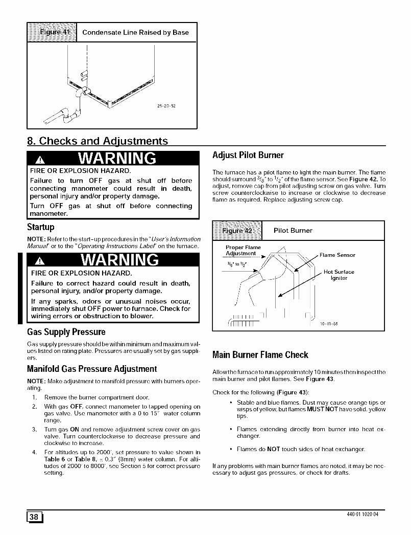
If you go away during the winter months and do not leave the heaton in your home, the plastic transition box and the condensate trapon the furnace must be protected from freeze damage.(SeeFigure 9 trough Figure 18)
1. Disconnect the 5/8" OD rubber hose from the vent drain fit-ting that is located downstream of the combustion blower.Insert a funnel into the hose and pour four(4) ounces of sani-tary type (RV) antifreeze into the condensate trap. Recon-nect the 5/8" OD rubber hose to the stub on the vent drain
fitting. Secure with the hose clamp.
2. Disconnect the 3/4" OD rubber hose from the condensate
trap. Insert a funnel into the hose and and pour four(4)ounces of sanitary type (RV) antifreeze into the plastic Tran-sition box. Squeeze the hose together near the end andquickly reconnect the 3/4" OD rubber hose to the stub on thecondensate trap. Secure with the hose clamp.
When you return home, your furnace will be ready to start, as it isnot necessary to drain the antifreeze from the furnace.
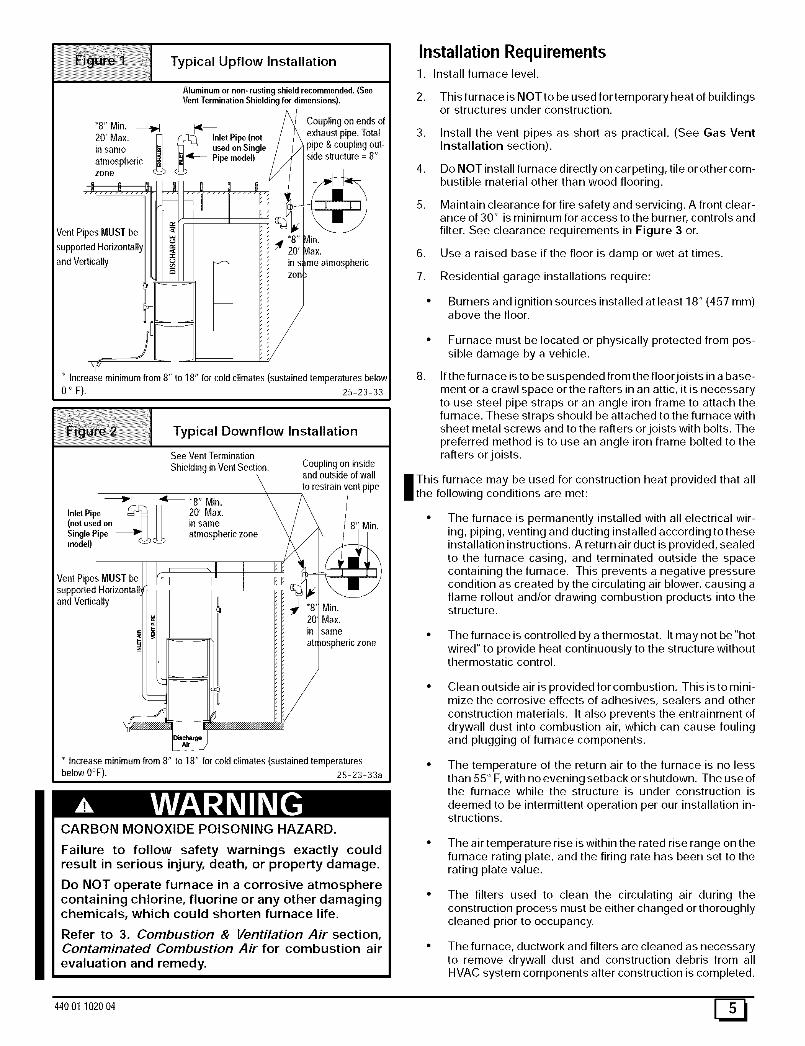
2. Installation
CARBON MONOXIDE POISONING HAZARD
Failure to properly vent this furnace or otherappliances could result in death, personal injuryand/or property damage.
This furnace can NOT be common vented orconnected to any type B, BW or L vent or ventconnector, nor to any portion of a factory-built ormasonry chimney. If this furnace is replacing a3reviously common-vented furnace, it may benecessary to resize the existing vent and chimney to3revent oversizing problems for the otherremaining appliance(s). See Venting and Combus-tion Air Check in Gas Vent Installation section. Thisfurnace MUST be vented to the outside.
Location and Clearances
If furnace is a replacement, it is usually best to install the fur-nace where the old one was. Choose the location or evalu-
ate the existing location based upon the minimum clearanceand furnace dimensions (Figure 3).
FROZEN AND BURST WATER PIPE HAZARD
Failure to protect against the risk of freezing couldresult in property damage and/or personal injury.
Special precautions MUST be made if installingfurnace in an area which may drop below freezing.This can cause improper operation or damage toequipment. If furnace environment has the potentialof freezing, the drain trap and drainline must beprotected. The use of electric heat tape or RVantifreeze is recommended for these installations.
(See "Condensate Trap Freeze Protection Section")
1, Refer to Figure 1 or Figure 2 for typical installation and ba-sic connecting parts required. Refer to Figure 4 for typicalhorizontal direct vent installation and basic connecting partsrequired. Supply and return air plenums and duct are alsorequired.
Do NOT operate furnace in a corrosive atmospherecontaining chlorine, fluorine or any other damagingchemicals. Refer to Combustion & Ventilation Air section,Contaminated Combustion Air.
2. This furnace is NOT to be used for temporary heat of buildingsor structures under construction.
3. Install the vent pipes as short as practical. (See Gas VentInstallation section).
4. Do NOT install furnace directly on carpeting, tile or other com-bustible material other than wood flooring.
5. Maintain clearance for fire safety and servicing. A front clear-ance of 30" is minimum for access to the burner, controls and
filter. See clearance requirements in Figure 3 or.
6. Use a raised base if the floor is damp or wet at times.
7. Residential garage installations require:
• Burners and ignition sources installed at least 18" (457 ram)above the floor.
8.
Furnace must be located or physically protected from pos-sible damage by a vehicle.
If the furnace is to be suspended from the floorjoists in a base-ment or a crawl space or the rafters in an attic, it is necessaryto use steel pipe straps or an angle iron frame to attach thefurnace. These straps should be attached to the furnace withsheet metal screws and to the rafters or joists with bolts. Thepreferred method is to use an angle iron frame bolted to therafters or joists.
I his furnace may be used for construction heat provided that allthe following conditions are met:
The furnace is permanently installed with all electrical wir-ing, piping, venting and ducting installed according to theseinstallation instructions. A return air duct is provided, sealedto the furnace casing, and terminated outside the spacecontaining the furnace. This prevents a negative pressurecondition as created by the circulating air blower, causing aflame rollout and/or drawing combustion products into thestructure.
• The furnace is controlled by a thermostat. It may not be "hotwired" to provide heat continuously to the structure withoutthermostatic control.
Clean outside air is provided for combustion. This is to mini-mize the corrosive effects of adhesives, sealers and other
construction materials. It also prevents the entrainment ofdrywall dust into combustion air, which can cause foulingand plugging of furnace components.
The temperature of the return air to the furnace is no lessthan 55 ° F, with no evening setback or shutdown. The use ofthe furnace while the structure is under construction is
deemed to be intermittent operation per our installation in-structions.
• The air temperature rise is within the rated rise range on thefurnace rating plate, and the firing rate has been set to therating plate value.
• The filters used to clean the circulating air during theconstruction process must be either changed or thoroughlycleaned prior to occupancy.
• The furnace, ductwork and filters are cleaned as necessary
to remove drywall dust and construction debris from allHVAC system components after construction is completed.
44001 102004 [_
|
I
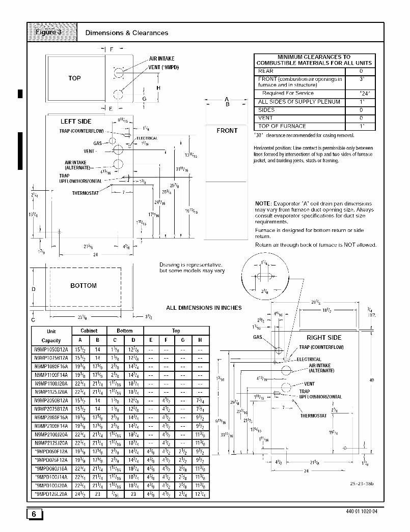
Dimensions & Clearances
17/8
Unit
Capacity
NOMP1050B12A
N9MP1075B12A
NgMP1080F16A
N9MP1100F14A
NgMP1100J20A
NOMP1125J20A
NOMP2050B12A
NOMP2075B12A
NgMP2080F16A
NgMP2100F14A
NOMP2100J20A
NOMP2125J20A
*9MPDO50F12A
*9MPDO75F12A
*9MPDOSOJ16A
*9MPD100J14A
*9MPDIOOJ20A
*9MPD125L20A
TOP
r-- ]
]
LEFT SIDE [-_ _
TRAP(COUNTERFLOW)_GASt_
VENT )AIR INTAKE _" )(ALTERNATE)_
413/16_TRAPUPFLOWtHORIZONTAL_
THERMOSTA_=_ 7-
215/8_ 47/
24
11/4
/ ELECTRICAL11/16
31
2(, f8
3/4
1/1
113/1
_A_B_
FRONT
Drawing is representative,but some models may vary
BOTTOM
-- 23118 _,_ 37/8
Cabinet Bottom
ALL DIMENSIONS IN INCHES
MINIMUM CLEARANCES TOCOMBUSTIBLE MATERIALS FOR ALL UNITS
REAR O
FRONT (combustion air openings in 3"furnace and in structure)
Required For Service *24"
ALL SIDES Of SUPPLY PLENUM 1"
SIDES O
VENT O
TOP OF FURNACE 1"
*30" clearancerecommendedfor casingremoval.
Horizontalposition:Linecontactispermissibleonly betweenlinesformed by intersectionsof top and two sidesof furnacejacket,and buildingjoists, studs or framing.
NOTE: Evaporator "A" coil drain pan dimensionsmay vary from furnace duct opening size, AIways
consult evaporator specifications for duct size
requirements,
Furnace is designed for bottom return or sidereturn.
Return air through back of furnace is NOT allowed.
28112/
16_/ _ 18112
23/8 --
1r/16_ /
/ RIGHT SIDEGAS\/
//TRAP (COUNTERFLOW)
_I_ELECTRICAL
AIRINTAKE/(ALTERNATE)
413116_ _'_/VENT
11111_ _ TRAPowIHORIZONTAL
19114
L _
47/8 _=_215/8
24
17/8
25-23-36b
E_ 440 01 1020 04
Installation Positions
This furnace can be installed in an upflow, horizontal (either left orright) or downflow airflow position. DO NOT install this furnace onits back. For the upflow position, the return air ductwork can be at-
tached to either the left or right side panel and/or the bottom. Forhorizontal and downflow positions, the return air ductwork must beattached to the bottom. The return air ductwork must never be at-tached to the back of the furnace.
Furnace Installation Considerations
The installation of the furnace for a given application will dictate theposition of the furnace, the airflow, ductwork connections, vent and
combustion air piping. Consideration must be given to the follow-ing:
Condensate Trap and Drain Lines
The supplied condensate trap must be attached to the furnaceside panel on either the left or right side. For horizontal installa-tions, the drain trap is vertically attached to the side panel belowthe furnace. A minimum clearance of 6" below the furnace is re-
quired for the condensate trap. Downward slope of the conden-sate drain line from the condensate trap to the drain location mustbe provided. Adequate freeze protection of the drain trap and the
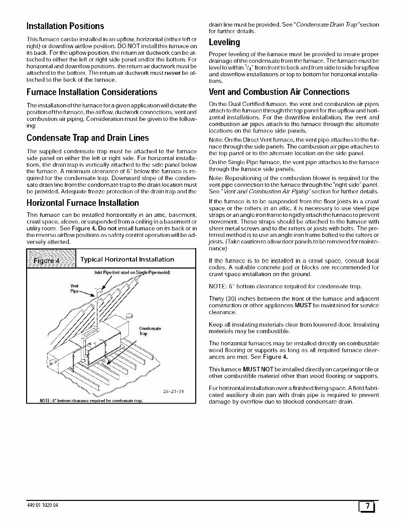
Horizontal Furnace Installation
This furnace can be installed horizontally in an attic, basement,crawl space, alcove, or suspended from a ceiling in a basement orutility room. See Figure 4. Do not install furnace on its back or inthe reverse airflow positions as safety control operation will be ad-versely affected.
drain line must be provided. See "Condensate Drain Trap"sectionfor further details.
LevelingProper leveling of the furnace must be provided to insure proper
drainage of the condensate from the furnace. The furnace must belevel to within 114" from front to back and from side to side for upflow
and downflow installations or top to bottom for horizontal installa-tions.
Vent and Combustion Air Connections
On the Dual Certified furnace, the vent and combustion air pipesattach to the furnace through the top panel for the upflow and hori-zontal installations. For the downflow installation, the vent and
combustion air pipes attach to the furnace through the alternatelocations on the furnace side panels.
Note: On the Direct Vent furnace, the vent pipe attaches to the fur-nace through the side panels. The combustion air pipe attaches tothe top panel or to the alternate location on the side panel.
On the Single Pipe furnace, the vent pipe attaches to the furnacethrough the furnace side panels.
Note: Repositioning of the combustion blower is required for thevent pipe connection to the furnace through the "right side" panel.See "Vent and Combustion Air Piping"section for further details.
If the furnace is to be suspended from the floor joists in a crawlspace or the rafters in an attic, it is necessary to use steel pipe
straps or an angle iron frame to rigidly attach the furnace to preventmovement. These straps should be attached to the furnace withsheet metal screws and to the rafters or joists with bolts. The pre-ferred method is to use an angle iron frame bolted to the rafters or
joists. (Take caution to allowdoor panels to be removed for mainte-nance)
If the furnace is to be installed in a crawl space, consult localcodes. A suitable concrete pad or blocks are recommended forcrawl space installation on the ground.
NOTE: 6" bottom clearance required for condensate trap.
Thirty (30) inches between the front of the furnace and adjacentconstruction or other appliances MUST be maintained for serviceclearance.
Keep all insulating materials clear from Iouvered door. Insulatingmaterials may be combustible.
The horizontal furnaces may be installed directly on combustiblewood flooring or supports as long as all required furnace clear-ances are met. See Figure 4.
This furnace MUST NOT be installed directly on carpeting or tile orother combustible material other than wood flooring or supports.
For horizontal installation over a finished living space. A field fabri-cated auxiliary drain pan with drain pipe is required to preventdamage by overflow due to blocked condensate drain.
44001 102004
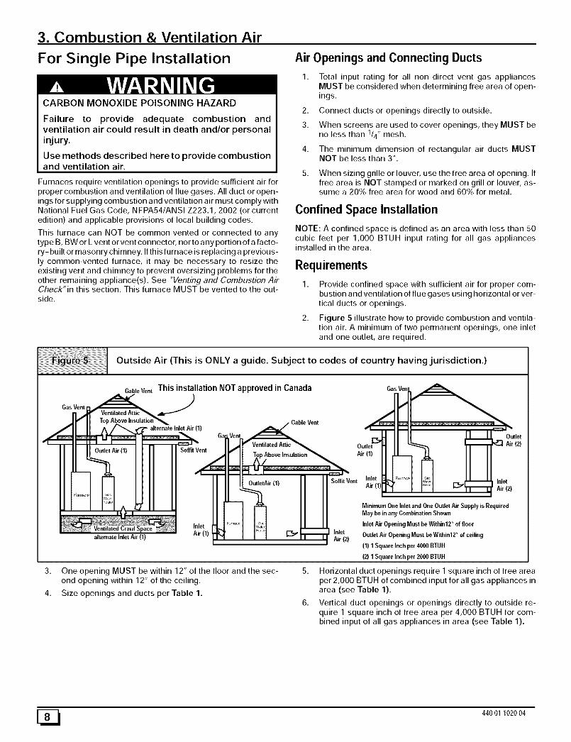
3. Combustion & Ventilation Air
For Single Pipe Installation
CARBON MONOXIDE POISONING HAZARD
Failure to provide adequate combustion andventilation air could result in death and/or personalinjury.
Use methods described here to provide combustionand ventilation air.
Furnaces require ventilation openings to provide sufficient air forproper combustion and ventilation of flue gases. All duct or open-ings for supplying combustion and ventilation air must comply withNational Fuel Gas Code, NFPA54/ANSI Z223.1, 2002 (or current
edition) and applicable provisions of local building codes.
This furnace can NOT be common vented or connected to anytype B, BW or L vent or vent connector, nor to any portion of a facto-ry- built or masonry chimney. If this furnace is replacing a previous-ly common-vented furnace, it may be necessary to resize theexisting vent and chimney to prevent oversizing problems for theother remaining appliance(s). See "Venting and Combustion AirCheck"in this section, This furnace MUST be vented to the out-side.
Air Openings and Connecting Ducts
2,
3.
Total input rating for all non direct vent gas appliancesMUST be considered when determining free area of open-ings.
Connect ducts or openings directly to outside.
When screens are used to cover openings, they MUST beno less than 1/4" mesh.
The minimum dimension of rectangular air ducts MUSTNOT be less than 3".
5. When sizing grille or louver, use the free area of opening. Iffree area is NOT stamped or marked on grill or louver, as-sume a 20% free area for wood and 60% for metal.
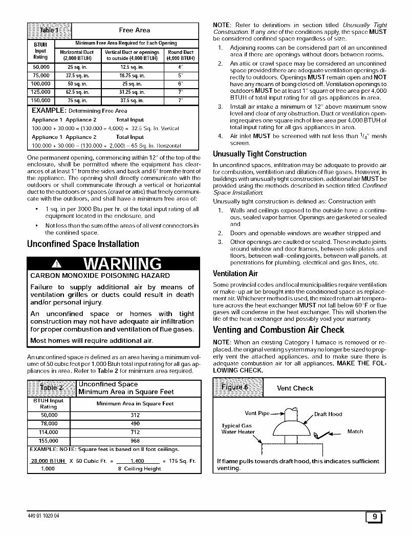
Confined Space Installation
NOTE: A confined space is defined as an area with less than 50cubic feet per 1,000 BTUH input rating for all gas appliancesinstalled in the area.
Requirements
Provide confined space with sufficient air for proper com-bustion and ventilation of flue gases using horizontal or ver-tical ducts or openings.
Figure 5 illustrate how to provide combustion and ventila-tion air. A minimum of two permanent openings, one inletand one outlet, are required.
Outside Air (This is ONLY a guide. Subject to codes of country having jurisdiction.)
Gas Vent
CableVent This installation NOT approved in Canada GasVen_.
.Jx. c,,en .... ,dNI a___aOut,et
Outlet Air (1) Soffit Vent /') I I _ ;_.-u,atio.'>_ .ir(1)I JL__.q3 II IIII 11I II II
r-q I I ]- OutletAir'l' _] I SoffitVent In.let _4........I I_;:;:,1 ___.L_U, tnlet
I I A _ _ -- _ II I MinimumOnelnletandOneOutletAirSupplyisRequiredI I II I May bein any Combination Shown
Inlet _ ,r_o, I _"_1 I I I Inlet Air Opening Must be Within12" of floor
alternate lnlet Air (1) AIr(l) _ Iq [_:_"r_r _ilrei2 ) OutletAirOpeningMustbeWithinl2"ofceiling
(1)1SquareInchper4000BTUH
(2)1SquareInchper2000B]-UH
3. One opening MUST be within 12" of the floor and the sec-ond opening within 12" of the ceiling.
4. Size openings and ducts per Table 1.
5. Horizontal duct openings require I square inch of free areaper 2,000 BTUH of combined input for all gas appliances inarea (see Table 1).
6. Vertical duct openings or openings directly to outside re-quire 1 square inch of free area per 4,000 BTUH for com-bined input of all gas appliances in area (see Table 1).
One permanent opening, commencing within 12" of the top of theenclosure, shall be permitted where the equipment has clear-ances of at least 1" from the sides and back and 6" from the front of
the appliance. The opening shall directly communicate with theoutdoors or shall communicate through a vertical or horizontalduct to the outdoors or spaces (crawl or attic) that freely communi-cate with the outdoors, and shall have a minimum free area of:
• 1 sq. in per 3000 Btu per hr. of the total input rating of allequipment located in the enclosure, and
• Not less than the sum ofthe areas of all vent connectors in
the confined space.
Unconfined Space Installation
CARBON MONOXIDE POISONING HAZARD
Failure to supply additional air by means ofventilation grilles or ducts could result in deathand/or personal injury.
An unconfined space or homes with tightconstruction may not have adequate air infiltrationfor proper combustion and ventilation of flue gases.
Most homes will require additional air.
BTUH InputRating
50,000
78,000
114,000
155,000
An unconfined space is defined as an area having a minimum vol-ume of 50 cubic feet per 1,000 Btuh total input rating for all gas ap-pliances in area. Refer to Table 2 for minimum area required.
I Unconfined SpaceMinimum Area in Square Feet
Minimum Area in Square Feet
312
49O
712
968
EXAMPLE: NOTE: Square feet is based on 8 foot ceilings.
28,000 BTUH X 50 Cubic Ft. = 1,400 = 175 Sq. Ft.
1,000 8' Ceiling Height
NOTE: Refer to definitions in section titled Unusually TightConstruction, If any one of the conditions apply, the space MUSTbe considered confined space regardless of size.
1. Adjoining rooms can be considered part of an unconfinedarea if there are openings without doors between rooms.
2. An attic or crawl space may be considered an unconfinedspace provided there are adequate ventilation openings di-rectly to outdoors. Openings MUST remain open and NOThave any means of being closed off. Ventilation openings tooutdoors MUST be at least 1" square of free area per 4,000BTUH of total input rating for all gas appliances in area.
3. Install air intake a minimum of 12" above maximum snow
level and clear of any obstruction. Duct or ventilation open-ing requires one square inch of free area per 4,000 BTU H oftotal input rating for all gas appliances in area.
4. Air inlet MUST be screened with not less than 1/4" meshscreen.
Unusually Tight Construction
In unconfined spaces, infiltration may be adequate to provide airfor combustion, ventilation and dilution of flue gases. However, inbuildings with unusually tight construction, additional air MUST beprovided using the methods described in section titled ConfinedSpace Installation:
Unusually tight construction is defined as: Construction with
1. Walls and ceilings exposed to the outside have a continu-ous, sealed vapor barrier. Openings are gasketed or sealedand
2,
3.
Doors and openable windows are weather stripped and
Other openings are caulked or sealed. These includejointsaround window and door frames, between sole plates andfloors, between wall-ceiling joints, between wall panels, atpenetrations for plumbing, electrical and gas lines, etc.
Ventilation Air
Some provincial codes and local municipalities require ventilation
or make-up air be brought into the conditioned space as replace-ment air. Whichever method is used, the mixed return air tempera-ture across the heat exchanger MUST not fall below 60°F or fluegases will condense in the heat exchanger. This will shorten the
life of the heat exchanger and possibly void your warranty.
Venting and Combustion Air Check
NOTE: When an existing Category I furnace is removed or re-placed, the original venting system may no longer be sized to prop-erly vent the attached appliances, and to make sure there isadequate combustion air for all appliances, MAKE THE FOL-LOWING CHECK.
Vent Check
Vent Pipe----_,l I 7 Draft Hood
Typical Gas f _'_
WaterHeate / i i MatchI I
If flame pulls towards draft hood, this indicates sufficient
venting.
44001 102004 [_
CARBON MONOXIDE POISONING HAZARD
Failure to follow the steps outlined below for eachappliance connected to the venting system beingplaced into operation, could result in carbonmonoxide poisoning or death:
The following steps shall be followed for eachappliance connected to the venting system being
placed into operation, while all other appliancesconnected to the venting system are not inoperation:
1. Seal any unused openings in the venting system.
2. Inspect the venting system for proper size and horizontalpitch, as required in the National Fuel Gas Code, ANSIZ223,1/NFPA 54 or CSA B149, 1, Natural Gas and
Propane Installation Code and these instructions. Deter-mine that there is no blockage or restriction, leakage,corrosion and other deficiencies which could cause anunsafe condition.
3. As far as practical, close all building doors and windowsand all doors between the space in which the appliance(s)connected to the venting system are located and otherspaces of the building.
4. Close fireplace dampers.
5. Turn on clothes dryers and any appliance not connectedto the venting system. Turn on any exhaust fans, such asrange hoods and bathroom exhausts, so they areoperating at maximum speed. Do not operate a summerexhaust fan.
6. Followthe lighting instructions. Place the appliance beinginspected into operation. Adjust the thermostat soappliance is operating continuously.
7. Test for spillage from draft hood equipped appliances atthe draft hood relief opening after 5 minutes of main burneroperation. Use the flame of a match or candle. (Figure 6)
8. If improper venting is observed, during any of the abovetests, the venting system must be corrected inaccordance with the National Fuel Gas Code, ANSIZ223,1/NFPA 54 and/or CSA B149. 1, Natural Gas and
Propane Installation Code.
9. After it has been determined that each applianceconnected to the venting system properly vents whentested as outlined above, return doors, windows, exhaust
fans, fireplace dampers and any other gas-fired burning
appliance to their previous conditions of use.
For Two Pipe Installation
This furnace can NOT be common vented or connected to anytype B, BW or L vent or vent connector, nor to any portion of a facto-ry-built or masonry chimney. If this furnace is replacing a previous-ly common-vented furnace, it may be necessary to resize theexisting vent and chimney to prevent oversizing problems for theother remaining appliance(s). See "Venting and Combustion AirCheck"in this section, This furnace MUST be vented to the out-side.
4. Vent and Combustion Air Piping
CARBON MONOXIDE POISONING HAZARD.
Failure to properly vent this furnace could result indeath and/or personal injury.
Use methods described here to provide combustionand ventilation air.
Single Pipe (N9MP1 Models)
This furnace is certified as a category [V appliance. This furnace
requires ventilation openings to provide air for proper combustionand ventilation of flue gases. All duct or openings for supplying
combustion and ventilation air must comply with the gas codes orin absence of local codes, the applicable national codes.
When the installation is complete, see the" Venting and Combus-tion Air Che¢l_' in this manual.
Direct Vent (N9MP2 Models)This furnace is certified as a category ]V appliance. This furnaceuses outside air for combustion ONLY, it MUST be taken from the
same atmospheric pressure zone as the vent pipe. See ConfinedSpace Installation in the Combustion and Ventilation Air in thismanual.
Dual Certified (*9MPD Models)
This furnace is certified as a category ]V appliance. This furnacecan be installed as a direct vent furnace using outside air for com-
440 01 1020 04
bustionorthefurnacecanuseairfrominsidethestructureforcom-bustion.TheINLETairpipeisoptional.Ifcombustionaircomesfrominsidethestructure,adequatemakeupairMUSTbeprovidedtocompensateforoxygenburned.SeeConfined Space Installa-tion in the Combustion and Ventilation Air chapter. If combus-tion air is drawn from outside the structure, it MUST be taken from
the same atmospheric pressure zone as the vent pipe.
Contaminated Combustion Air
Installations in certain areas or types of structures will increase theexposure to chemicals or halogens that may harm the furnace.
The following areas or types of structures may contain or have ex-posure to the substances listed below. The installation must beevaluated carefully as it may be necessary to provide outside airfor combustion.
• Commercial buildings.
• Buildings with indoor pools.
• Furnaces installed in laundry rooms.
• Furnaces installed in hobby or craft rooms.
• Furnaces installed near chemical storage areas.
• Permanent wave solutions for hair.
• Chlorinated waxes and cleaners.
• Chlorine based swimming pool chemicals.
• Water softening chemicals.
• De-icing salts or chemicals.
• Carbon tetrachloride.
• Halogen type refrigerants.
• Cleaning solvents (such as perchloroethylene).
• Printing inks, paint removers, varnishes, etc.
• Hydrochloric acid.
• Sulfuric Acid.
• Solvent cements and glues.
• Antistatic fabric softeners for clothes dryers.
• Masonry acid washing materials.
Vent and Combustion Air Piping Guidelines
This furnace is approved for venting with Schedule 40 PVC,CPVC, ABS, Cellular Core pipe fittings and SDR-26 PVC.
NOTE: All PVC, CPVC, ABS, and Cellular Core pipe fittings, sol-vent cement, primers and procedures MUST conform to American
National Standard Institute and American Society for Testing andMaterials (ANSI/ASTM) standards.
NOTE: All vent piping MUST be installed in compliance with localcodes or ordinances, these instructions, good trade practices, andcodes of country having jurisdiction.
1. Determine the best routing and termination for the vent pipeand air inlet pipe by referring to all of the instructions andguidelines in this Section.
2. Determine the size required for the vent pipe and air inlet
pipe.
3. Loosely assemble all venting parts without adhesive (pipejoint cement) for correct fit before final assembly.
44001102004
4. Use of vertical piping is preferred because there will besome moisture in the flue gases that may condense as itleaves the vent pipe (See 5peciallnstruction ForHorizontalVents).
5. The vertical vent pipe MUST be supported so that no weightis allowed to rest on the combustion blower.
6. Exhaust vent piping or air inlet piping diameter MUST NOTbe reduced.
7. All exhaust vent piping from the furnace to terminationMUST slope upwards. A minimum of 1/4" per foot of run is
required to properly return condensate to the furnace drainsystem.
8. Use DWV type long radius elbows whenever possible, asthey provide for the minimum slope on horizontal runs andthey provide less resistance in the vent system. If DWV el-bows cannot be used, use two, 45 ° elbows when possible.On horizontal runs the elbows can be slightly misaligned toprovide the correct slope.
9. All horizontal pipe runs MUST be supported at least everyfive feet with galvanized strap or other rust resistant materi-al. NO sags or dips are permitted.
10. All vertical pipe runs MUST be supported every six feetwhere accessible.
11.
12.
The minimum pipe run length is 2'.
The piping can be run in the same chase or adjacent to sup-ply or vent pipe for water supply or waste plumbing. It canalso be run in the same chase with a vent from another 90+furnace.
NOTE: In NO case can the piping be run in a chase where
temperatures can exceed 140 ° F. or where radiated heatfrom adjacent surfaces would exceed 140 ° F.
13. The vent outlet MUST be installed to terminate in the same
atmospheric pressure zone as the combustion air inlet.
14. The vent system can be installed in an existing unusedchimney provided that:
• Both the exhaust vent and air intake run the length of thechimney.
• No other gas fired appliance or fireplace (solid fuel) is
vented into the chimney.
• The top of the chimney MUST be sealed flush or crownedup to seal against rain or melting snow so ONLY the pipingprotrudes.
15. Furnace applications with vertical vents requiring vent di-ameter increaser fittings must have increaser fittingsinstalled in vertical portion of the vent. Condensate will betrapped in the vent if the vent diameter is increased prior tohaving an elbow turned upward. This could cause nuisancetripping of the pressure switch.
Piping InsulationGuidelinesNOTE: Use closed cell, neoprene insulation or equivalent. If Fiber-glass or equivalent insulation is used it must have a vapor barrier.Use R values of 7 up to 10', R- 11 if exposure exceeds 10'. If Fiber-
glass insulation is used, exterior to the structure, the pipe MUSTbe boxed in and sealed against moisture.
1. When the vent or combustion air pipe height above the roofexceeds 30", or if an exterior vertical riser is used on a hori-
zontal vent to get above snow levels, the exterior portionMUST be insulated.
When combustion air inlet piping is installed above a sus-pended ceiling, the pipe MUST be insulated with moistureresistant insulation such as Armaflex or other equivalenttype of insulation.
E!9
3. Insulate combustion air inlet piping when run in warm, hu-mid spaces such as basements.
Sizing Combustion Air and Vent PipeConsult Table 3 or Table 4 to select the proper diameter exhaust
and combustion air piping. Exhaust and combustion air piping issized for each furnace Btuh size based on total lineal vent length(on inlet oroutlet side), and number of 90 ° elbows required. Two45 ° elbows can be substituted for one 90 ° elbow. The elbow or el-
bows used for vent termination outside the structure ARE counted,
including elbows needed to bring termination above expectedsnow levels. The elbow inside the furnace on the *9MPD IS NOTincluded in the count.
Pipe Diameter TableN9MP1 & *9MPD Models
50,000, 75,000 & 80,000 Btuh Furnaces
40' & (5) 90 ° elbows with 2" PVC pipe or70' & (5) 90 ° elbows with 3" PVC pipe
3' (91 cm) within 15' (4.5 m) above the meter/regulator
assembly
3' (91 cm)
6" (15cm)forappliances_<lO,OOOBTUH(3kW),9" (23cm)for appliances> 10,000Btah (3kW) and _<100,000Btah(30kW) and _<50,000Btuh(15kW), 12" (30 cm) for appliances> 50,000Btah(15kW)
6' (1.83m)
12" (30 cm) +
12" (30 cm)
N Clearance from a plumbing vent stack 3' (91 cm)
(1.) In accordance wifh the currem CSA B149.1, Natural Gas and Propane Installation Code
(2.) In accordance with the current ANSI Z223.1/NFPA 54, National Fuel Gas Code
# 18" (46 cm) above roof surface
+ Permitted only if veranda, porch, deck, or balcony is fully open on a minimum of two sides beneath the floor.
U.S. Installation (2)
12" (30cm)
6" (15 cm) for appliances_<10,000BTUH(3kW),9" (23 cm)for appliances>10,000Btuh(3 kW)and _<50,000Btuh(15kW),12" (30cm) for appliances>50,000Btub(15 kW)
3' (91 cm) within 15' (4.5 m) above the meter/regulator
assembly
6" (15cm)forappliances_<lO,OOOBTUH(3kW),9" (23cm)
for appliances > 10,000 Btah (3 kW) and _<50,000 Btuh (15kW), 12" (30 cm) for appliances > 50,000 Btuh (15 kW)
3' (91 cm) above if within 10' (3m horizontally)
12" (30 cm)
3' (91 cm)
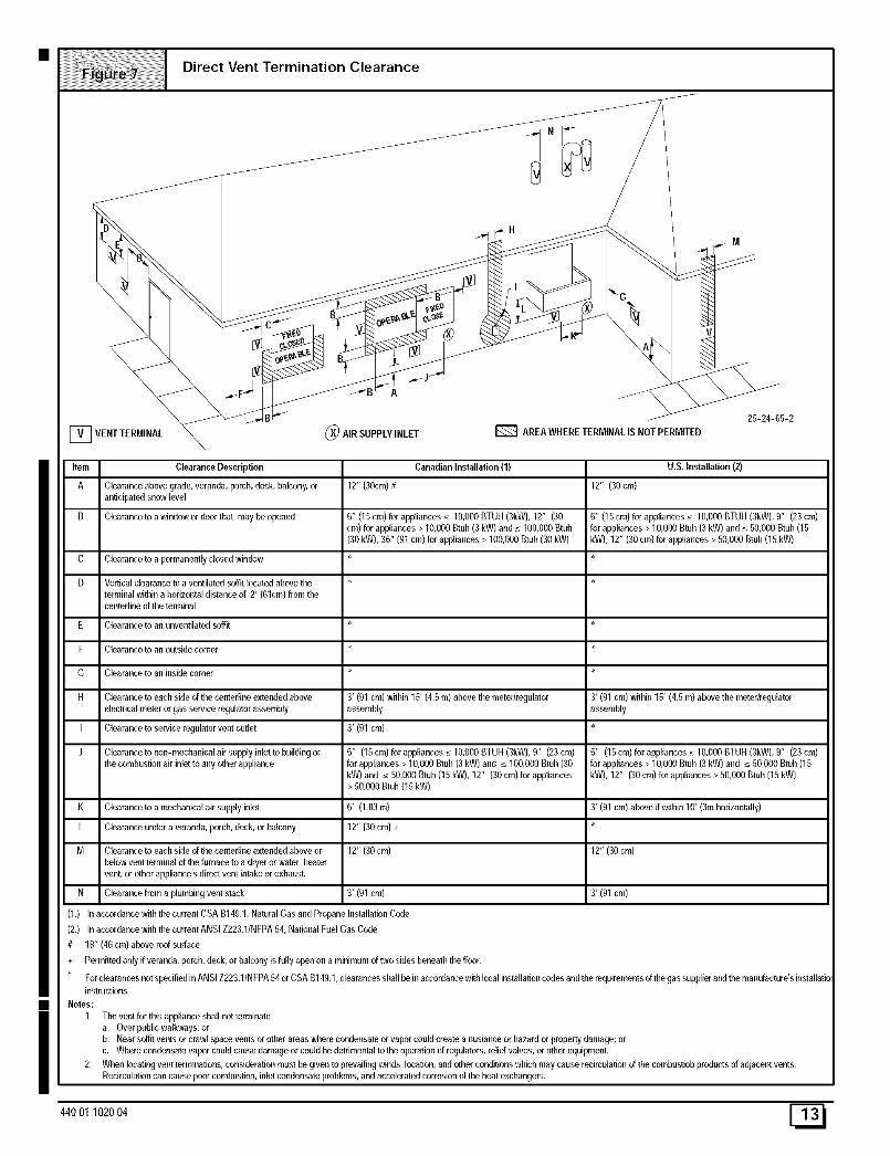
For clearances not specified in AN SI Z223.1/N FPA 54 or C SA B149.1, clearances shall be in accordance with local installation codes and the requirements of the gas supplier and the manufactare's installatioinstructions.
Notes:
1. The vent for this appliance shall not terminate
a. Over public walkways; or
b. Near soffit vents or crawl space veins or other areas where condensate or vapor could create a nusiance or hazard or property damage; or
c. Where condensate vapor could cause damage or could be detrimental to the operation of regulators, relief valves, or other equipment.
2. When locating vent terminations, consideration must be given to prevailing winds, location, and other conditions which may cause recirculation of the combustiob products of adjacent vents.
Recircula0on can cause poor combustion, inlet condensate problems, and accelerated corrosion of the heat exchangers.
440O1102004 E_
i
Item Clearance Descriptions
A Clearance above grade, veranda, porch, deck, balcony, or
anticipated snow level
B Clearance to a window or door that may be opened
D Vertical clearance to a ventilated soffit located above the *
terminal within a horizontal distance of 2' (61cm) from thecentedine of the terminal
E Clearance to an unventilated soffit *
F Clearance to an outside corner *
G Clearance to an inside comer *
H Clearance to each side of the centedine extended above
electrical meter or gas service regulator assembly
I Clearance to service regulator vent outlet
J Clearance to non-mechanical air supply inlet to building or
the combustion air inlet to any other appliance
K Clearance to a mechanical air supply inlet
L Clearance under a veranda, porch, deck, or balcony
M Clearance to each side of the centedine extended above or *
below vent terminal of the furnace to a dryer or water heater
vent, or other appliance's direct vent intake or exhaust.
N Clearance from a plumbing vent stack
3' (91 cm) within 15' (4.5 m) above the meter/regulator
assembly
3' (01 cm)
6" (15cm)forappliances_<10,OOOBTUH(3kW),12" (30cm) for appliances> 10,000Btub(3kW) and _<100,000Btuh(30 kW),36" (91 cm) for appliances> 100,000Btuh(30 kW)
6' (1.83m)
12" (30 cm) +
3' (91 cm)
U.S. Installation (2)
12" (30 cm)
4' (1,2 m) below or to the side of the opening. 1' (30 cm)
above the opening.
3' (91 cm) within 15' (4.fi m) above the meter/regulator
assembly
4' (1.2 m) below or to the side of opening: 1' (30 cm) above
opening.
3' (01 cm) above if within 10' (3m horizontally)
3' (91 cm)
(1.) In accordance with the currenl CSA B149.1, Natural Gas and Propane Installation Code
(2,) In accordance with the current ANSI Z223.1/NFPA fi4, Nafional Fuel Gas Cede
# 18" (46 cm) above roof surface
+ Permitted only if veranda, porch, deck, or balcony is fully open on a minimum of two sides beneath the floor.
For clearances not specified in ANSI Z223.1/NFPA 54 or CSA B149.1, clearances shall be in accordance with local installation codes and the requirements of the gas supplier and the manufacture'sinstallation instructions.
Notes:
1, The vent for this appliance shall not terminate
a. Over public walkways; or
b. Near soffit vents or crawl space vents or other areas where condensate or vapor could create a nusiance or hazard or property damage; orc. Where condensate vapor could cause damage or could be detrimental to the operafion of regulators, relief valves, or other equipment.
2. When locating vent terminations, consideration must be given to prevailing winds, location, and other conditions which may cause recirculation of the combusfiob products of adjacent vents.
Recirculafion can cause poor combustion, inlet condensate problems, and accelerated corrosion of the heat exchangers.
[_ 440 01 1020 04
CondensateDrainTrap
This furnace removes both sensible and latent heat from the prod-ucts of combustion. Removal of the latent heat results in con-
densation of the water vapor. The condensate is removed from thefurnace through the drains in the plastic transition and the vent fit-
ting. The drains connect to the externally mounted condensatedrain trap on the left or right side of the furnace.
The startup of a new furnace will involve a cycle or two of the fur-
nace to properly prime the condensate trap with water. Until thetrap is fully primed, some condensate will be pulled into the com-bustion blower. The furnace may cycle on the pressure switch con-
nected to the plastic transition box due to condensate buildup.
After the trap is primed, the condensate will start draining from thefurnace. The combustion blower will clear out any remaining con-densate in the blower housing through the vent fitting downstream
of the blower. Note that the condensate trap can also be primed bypouring water into the 1/2" drain hose. Remove the1/2 " ID drainhose from either the gutter or the white PVC Tee Trap. Using a fun-nel pour eight (8) ounces of water into 112" ID drain hose.Water will
flow through the drain hose and into the condensate drain trap.
This will prime both the vent and the transition sides of the trap. Re-connect the 1/2, ID drain hose to the original component, either thegutter or the PVC Tee Trap.
The condensate drain trap supplied with the furnace MUST beused. The drain connection on the condensate drain trap is sizedfor 3/4" PVC or CPVC pipe, however alternate 1/2" CPVC (nominal
5/8" O.D.) or vinyl tubing with a minimum inner diameter (I.D.) of5/8" may also be used, as allowed by local codes. Alternate drain
pipes and hoses may be used as allowed by local codes.
The drain line must maintain a I/4" per foot downward slope towardthe drain. 114"per foot is recommended. Installation of an overflowline is recommended when the 114" per foot slope to the conden-
sate drain cannot be maintained. See Figure 18 for proper routingand installation of the overflow.
DO NOT trap the drain line in any other location than at the con-densate drain trap supplied with the furnace.
FROZEN AND BURST WATER PIPE HAZARD
Failure to do so could result in burst water pipes,serious property damage and/or personal injury.
If a condensate pump is installed, a pluggedcondensate drain or a failed pump may cause thefurnace to shut down. Do not leave the homeunattended during freezing weather without turningoff water supply and draining water pipes orotherwise protecting against the risk of frozen pipes.
If possible DO NOT route the drain line where it may freeze. Thedrain line must terminate at an inside drain to prevent freezing ofthe condensate and possible property damage.
1. A condensate sump pump MUST be used if required by lo-cal codes, or if no indoor floor drain is available. The con-
densate pump must be approved for use with acidiccondensate.
2. A plugged condensate drain line or a failed condensatepump will allow condensate to spill. If the furnace is installedwhere a condensate spill could cause damage, it is recom-
mended that an auxiliary safety switch be installed to pre-vent operation of the equipment in the event of pump failureor plugged drain line. If used, an auxiliary safety switchshould be installed in the R circuit (low voltage) ONLY.
3. If the auxiliary switch in the condensate pump is used, thefurnace may shut down dueto a blocked condensate line orfailed pump. To prevent frozen water pipes see the "Frozen
Water Pipe Hazard" section on Page 4 of this manual.
Condensate Drain Trap Freeze Protection
Special precautions MUST be made if installing furnace in an areawhich may drop below freezing. This can cause improper opera-tion or damage to the equipment. If the the furnace environmenthas the potential of freezing, the drain trap and drain line must beprotected. Use 3 to 6 watt per foot at 11 5 volt, 40 ° F self-regulatingshielded and waterproof heat tape. Wrap the drain trap and drainline with the heat tape and secure with the ties. Follow the heattape manufacturer's recommendations.
44001 102004 E_I
Upflow Installations Top Vent
_ ellowor blackPlasticCaps(2)
Co_(Optional)
VentDrain& Clamps
Pressure Switch Detail
1/2" ID Drain
Drain Connector Black PVC3/4"PVC X l/z" CPVC(Loose partsbag)
Casing GrommetBlack Rubber5/8" ID(Loose parts bag)
Drain Tube(& Clamps) Black Rubber /8 ID,Cut length to fit (Loose partsbag)
ID RubberTube
StreetEIbow/'CPVC
(Loosepartsbag)
25-24-42
Upflow Installations Top Vent (SeeFigure 9)
Remove plug from the side of the furnace casing where Drain Tu bewill exit.
Install casing grommet (black rubber 5/8" ID grommet - in loose
parts bag)
Install the 1/2" CPVC street elbow on discharge of Trap
Install the black PVC tube connector (3/4" PVC x 1/2" CPVC from
loose parts bag) as shown in the illustration above.
Cut the black Drain Tube (5/8" ID - in loose parts bag) to length to
fit between Trap and tube connector through grommet.
Clamp both ends of the Drain Tube using clamps provided.
Glue the CPVC street elbow to the Trap using appropriate cleanerand solvent cement.
Connect the Tee trap and the main drain line exiting the casing asshown Figure 18.
Note: It is recommended that all PVC piping and fitting connec-tions be fit up and inspected before final cementing. Trap must be
primed before operation. Verify all condensate drain connec-tions are securely clamped. A coupling and clamps (in loose partbag) may be installed as shown for future servicing of the vent sys-tem.
[_ 440 01 1020 04
UpflowInstallationsVentthru LeftSide
Yellow or black Plastic Cap
2" PVCCoupling ONLY
Coupling
Vent Drain Either: The PVC& Clamps Drain Tee or a field
supplied 2" PVC Te_
Dual Pressure Switch Detail
DrainConnector Black PVC314"PVCX 112"CPVC(Loosepartsbag)
TeeTrapWhite PVC(loose partsbag)
Black (Movefrombottom of drain teeif installed)
Casing GrommetBlack Rubbers/8" ID(Loose parts bag)
oj
Single Pressure Switch
Sl8" ID Hose& Clamps
ID RubberTube
SIDE VIEW
,,,_ Rotate downward
NOTET Bw]t-in channel will
be angled 5° to 10° also.
Drain LineVentTee3/4"PVC or 1/2"CPVC (Fieldsupplied) 25-24-43
Upflow Installations Vent thru Left Side (See Figure 10)
Remove Drain Tee from inducer discharge and remove blackDrain Tube (1/2" ID) from bottom of Drain Tee. (*9MPD modelsonly)
Install Vent Pipe grommet in side of casing.
Cut an appropriate length of 2" PVC pipe long enough to exit thecabinet and connect the vent drain to either:
• A standard field supplied 2" PVC tee (N9MP1 and 2 models),or
• A 2" PVC coupling fastened onto the Drain Tee (*9MPD mod-els)
Install Tee trap into bottom of tee.
Install the 1/2" CPVC street elbow on discharge of Trap
Install the black PVC drain connector (3/4" PVC x 1/2" CPVC from
loose parts bag) as shown in the illustration above.
Cut the black Drain Tube (5/8" ID - in loose parts bag) to length to
fit between Trap and tube connector through grommet.
Clamp both ends of the Drain Tube using clamps provided.
Glue the CPVC street elbow to the Trap using appropriate cleanerand solvent cement.
Connect the Tee trap and the main drain line exiting the casing as
shown in Figure 18.
Note: It is recommended that all PVC piping and fitting connec-tions be fit up and inspected before final cementing. Both the in-
ternal Trap and the external Tee Trap must be primed beforeoperation. Verify all condensate drain connections are securelyclamped. A coupling and clamps (in loose part bag) may be
installed as shown for future servicing of the vent system.
440O1102004 E_
All ModelsVentthru RightSide
4}
Yellow or black Plastic Cap
Vent Drain
& Clamps
On SomeModelsONLY
& Clamps
SIDE VIEW
_otate downward
NOTE.'fBuilt-inchannelwillheangled 5° to10° also.
oJ
Dual Pressure Switch
2" PVC CouplingEither: The PVCDrain Teeor a field
supplied2" PVC Tee
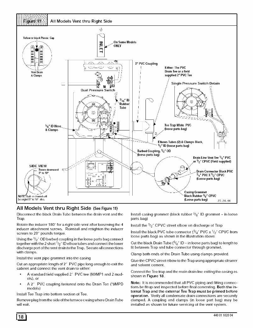
All Models Vent thru Right Side (SeeFigure 11)
Disconnect the black Drain Tube between the drain vent and the
Trap.
Rotate the inducer 180 ° for a right side vent after loosening the 4
inducer attachment screws. Reinstall and retighten the inducerscrews to 20" pounds torque.
Using the 1/2" OD barbed coupling in the loose parts bag connect1 ,together with the 2 short /2' ID elbowtubes and connect the lower
discharge port of the vent drain to the Trap. Secure all connections
with clamps.
Install the vent pipe grommet into the casing
Cut an appropriate length of 2" PVC pipe long enough to exit thecabinet and connect the vent drain to either:
• A standard field supplied 2" PVC tee (N9MP1 and 2 mod-els), or
• A 2" PVC coupling fastened onto the Drain Tee (*9MPDmodels)
Install Tee Trap into bottom section of Tee.
Remove plug from the side of the furnace casing where Drain Tu bewill exit.
Single Pressure Switch Detain
TeeTrap White PVC
ElbowsTubes (2) & Clamps Black,1/z" ID (loose partsbag)
Barbed Coupling, 112"ODparts bag)
Drain Line VentTee3/4"PVCCPVC(Field supplied)
314"PVCX 1/2" CPVC(Loose partsbag)
Casing Grommet
"Black Rubber sis" CPVC
(Loose parts bag) 25-24-44
Install casing grommet (black rubber 5/8" ID grommet - in loose
parts bag)
Install the 1/2" CPVC street elbow on discharge of Trap
Install the black PVC tube connector (3/4" PVC x 1/2" CPVC fromloose parts bag) as shown in the illustration above
Cut the black Drain Tube (5/8" ID - in loose parts bag) to length to
fit between Trap and tube connector through grommet.
Clamp both ends of the Drain Tube using clamps provided.
Glue the CPVC street elbow to the Trap using appropriate cleanerand solvent cement.
Connect the Tee trap and the main drain line exiting the casing asshown in Figure 18.
Note: It is recommended that all PVC piping and fitting connec-tions be fit up and inspected before final cementing. Both the in-
ternal Trap and the external Tee Trap must be primed beforeoperation. Verify all condensate drain connections are securelyclamped. A coupling and clamps (in loose part bag) may be
installed as shown for future servicing of the vent system.
[_ 440 01 1020 04
DownflowLeftSide Vent and Trap
Yellow or black Plastic Cap
VentDrain
& Clamps
Coupling&Clamps >_
(Optional)_ I._
]|mm|l
Either: The PrODrain Teeor a fieldsupplied 2" PVC Tee
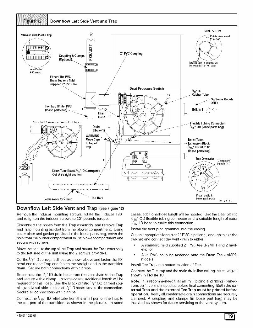
Remove the inducer mounting screws, rotate the inducer 180 °and retighten the inducer screws to 20" pounds torque.
Disconnect the hoses from the Trap assembly, and remove Trap
and Trap mounting bracket from the blower compartment. Usingcover plate and gasket provided in the loose parts bag, cover the
hole from the burner compartment to the blower compartment andsecure with screws.
Move the caps to the top of the Trap and mount the Trap externallyto the left side of the unit using the 2 screws provided.
Cut the 5/8" ID corrugated hose as shown above and fasten the 90 °
bend end to the Trap and fasten the straight end to the transitiondrain. Secure both connections with clamps.
Reconnect the 1/2" ID drain hose from the vent drain to the Trap
and secure with a clamp.. In some cases, additional length will berequired for this hose. Use the Black plastic 1/2" OD barbed cou-
pling and a suitable section of 1/2" ID hose to make the connection.Secure all connections with clamps
Connect the 3/16" ID relief tube from the small port on the Trap to
the top port of the transition as shown in the picture. In some
cases, additional hose length will be needed. Use the clear plastic3/16" OD flexible tubing connector and a suitable length of extra3/16" ID hose to make this connection.
Install the vent pipe grommet into the casing
Cut an appropriate length of 2" PVC pipe long, enough to exit thecabinet and connect the vent drain to either:
• A standard field supplied 2" PVC tee (N9MP1 and 2 mod-els), or
• A 2" PVC coupling fastened onto the Drain Tee (*9MPDmodels)
Install Tee Trap into bottom section of Tee.
Connect the Tee trap and the main drain line exiting the casing as
shown in Figure 18.
Note: It is recommended that all PVC piping and fitting connec-tions be fit up and inspected before final cementing. Both the ex-
ternal Trap and the external Tee Trap must be primed beforeoperation. Verify all condensate drain connections are securely
clamped. A coupling and clamps (in loose part bag) may beinstalled as shown for future servicing of the vent system.
44001 102004 E_
Downflow Right Side Vent and Trap
Yellow or black Plastic Cap
/
Vent Drain
&Clamps
SIDE VIEW
,_Rotate downward
NOTE.'_Built-in channel will
be angled 5° to 10° also.
Single Pressure Switch Detail
Splice ConnectorBarbed
Dual Pressure Switch
Drain TubeBlack, sis"ID Corrugated
PVC3/4"
Trap Connection_Clamp ears '_
ointed OUT
3/16" IDRubber Tube
112"IDDrain Hose &
Clamps
On Some
ModelsONLY
Pmassemble&insert intofurnace
Coupling & Clamps
2" PVCCoupling
Either:The PVC
supplied 2" PVC Tee
WARNINGMove Capsto top oftrap
White PVC(loose partsbag)
Drain Tube, (&Clamps)Black, s/8" ID Cut to fit(looseparts bag)
25-24-46
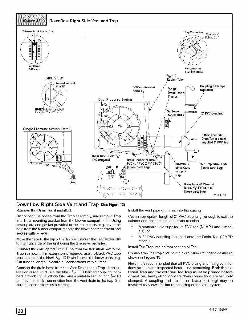
Downflow Right Side Vent and Trap (SeeFigure 13)
Remove the Drain Tee if installed.
Disconnect the hoses from the Trap assembly, and remove Trapand Trap mounting bracket from the blower compartment. Using
cover plate and gasket provided in the loose parts bag, cover thehole from the burner compartment to the blower compartment andsecure with screws.
Move the caps to the top of the Trap and mount the Trap externallyto the right side of the unit using the 2 screws provided.
Connect the corrugated Drain Tube from the transition box to the
Trap as shown. If an extension is required, use the black PVC tubeconnector and the black 5/8" ID Drain Tube in the loose parts bag.
Cut tube to length. Secure all connections with clamps.
Connect the drain hose from the Vent Drain to the Trap. If an ex-tension is required, use the black 1/2" OD barbed coupling, con-nect a black 1/2" ID elbow tube and a suitable section of a 1/2" ID
drain tube to make connection from the vent drain to the trap. Se-
cure all connections with clamps.
Install the vent pipe grommet into the casing
Cut an appropriate length of 2" PVC pipe long, enough to exit thecabinet and connect the vent drain to either:
• A standard field supplied 2" PVC tee (N9MP1 and 2 mod-els), or
• A 2" PVC coupling fastened onto the Drain Tee ('9MPDmodels)
Install Tee Trap into bottom section of Tee.
Connect the Tee trap and the main drain line exiting the casing as
shown in Figure 18.
Note: It is recommended that all PVC piping and fitting connec-tions be fit up and inspected before final cementing. Both the ex-
ternal Trap and the external Tee Trap must be primed beforeoperation. Verify all condensate drain connections are securelyclamped. A coupling and clamps (in loose part bag) may be
installed as shown for future servicing of the vent system.
[_ 440 01 1020 04
Vent Drain
& Clamps
Horizontal Left Thru Top
Yellowor blackPlastic
Alternate Orienation
Single Pressure Switch DetailTrap Connection
_ %lamp ears"
Pointed OUT
Preassemble &
insert into furnace
]
3116" ID
Dual Pressure Switch _Rubber Tube
_I _ ReliefTube
' i _io16"neODtoFr lexibletubing
_ Relief Tube Extension
Field (Optional)SuppliedTee
TeeTrapWhite PVC Cap and Clamp(loose parts bag) Open End
1/2" ID DrainHose&
ClampsTubeBlack, /8 ID Corrugated
Cut at straight section
Leaveroomfor clamp Cut Here
25-24-47
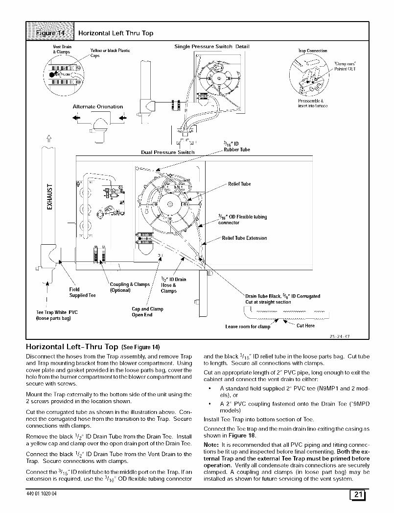
Horizontal Left-Thru Top (SeeFigure14)
Disconnect the hoses from the Trap assembly, and remove Trap
and Trap mounting bracket from the blower compartment. Usingcover plate and gasket provided in the loose parts bag, cover the
hole from the burner compartment to the blower compartment andsecure with screws.
Mount the Trap externally to the bottom side of the unit using the2 screws provided in the location shown.
Cut the corrugated tube as shown in the illustration above. Con-nect the corrugated hose from the transition to the Trap. Secureconnections with clamps.
Remove the black I/2" ID Drain Tube from the Drain Tee. Install
a yellow cap and clamp over the open drain port of the Drain Tee.
Connect the black I/2" ID Drain Tube from the Vent Drain to the
Trap. Secure connections with clamps.
Connect the 3/16" ID relief tube to the middle port on the Trap. If an
extension is required, use the 3116" OD flexible tubing connector
and the black 3/16" ID relief tube in the loose parts bag. Cut tube
to length. Secure all connections with clamps.
Cut an appropriate length of 2" PVC pipe, long enough to exit thecabinet and connect the vent drain to either:
• A standard field supplied 2" PVC tee (N9MP1 and 2 mod-els), or
• A 2" PVC coupling fastened onto the Drain Tee (_9MPDmodels)
Install Tee Trap into bottom section of Tee.
Connect the Tee trap and the main drain line exiting the casing asshown in Figure 18.
Note: It is recommended that all PVC piping and fitting connec-tions be fit up and inspected before final cementing. Both the ex-
ternal Trap and the external Tee Trap must be primed beforeoperation. Verify all condensate drain connections are securely
clamped. A coupling and clamps (in loose part bag) may beinstalled as shown for future servicing of the vent system.
44001 102004 [_
Horizontal Left-Side Vent
Alternate Orienation
Field
Supplied Tee_
TeeTrapWhite PVC
(loose partsbag)
DrainTube Black, /8 ID CorrugatedCut atstraight section
I
Leav_ Cut Here
Single Pressure Switch Detail
Level or Sloped towards Tee
Dual Pressure Switch
3/16"ID Ru/bherTube
Relief Tube /
/U Splice Connector
Relief Tube Extension
Yellow or black
VentDrain
& Clamps
1/2" ID Drain Elbow_Drain Hose& SpliceConnector(Cut-to- fit)
,5/8" IDCorrugated
WARNING
MoveCaps totop of trap
25-24-48
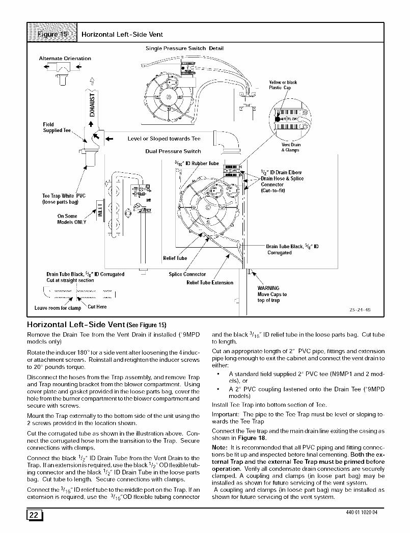
Horizontal Left-Side Vent (SeeFigure 15)
Remove the Drain Tee from the Vent Drain if installed (_9MPD
models only)
Rotate the inducer 180 ° for a side vent after loosening the 4 induc-
er attachment screws. Reinstall and retighten the inducer screwsto 20" pounds torque.
Disconnect the hoses from the Trap assembly, and remove Trapand Trap mounting bracket from the blower compartment. Using
cover plate and gasket provided in the loose parts bag, cover thehole from the burner compartment to the blower compartment andsecure with screws.
Mount the Trap externally to the bottom side of the unit using the2 screws provided in the location shown.
Cut the corrugated tube as shown in the illustration above. Con-
nect the corrugated hose from the transition to the Trap. Secure
connections with clamps.
Connect the black 1/2" ID Drain Tube from the Vent Drain to theTrap. If an extension is required, use the black 1/2" OD flexibletub-
ing connector and the black 1/2" ID Drain Tube in the loose partsbag. Cut tube to length. Secure connections with clamps.
Connect the 3/16" ID relief tube to the middle port on the Trap. If an
extension is required, use the 3116"0D flexible tubing connector
and the black 3/16" ID relief tube in the loose parts bag. Cut tube
to length.
Cut an appropriate length of 2" PVC pipe, fittings and extensionpipe long enough to exit the cabinet and connect the vent drain toeither:
• A standard field supplied 2" PVC tee (N9MP1 and 2 mod-els), or
• A 2" PVC coupling fastened onto the Drain Tee (*9MPDmodels)
Install Tee Trap into bottom section of Tee.
Important: The pipe to the Tee Trap must be level or sloping to-
wards the Tee Trap
Connect the Tee trap and the main drain line exiting the casing asshown in Figure 18.
Note: It is recommended that all PVC piping and fitting connec-
tions be fit up and inspected before final cementing. Both the ex-ternal Trap and the external Tee Trap must be primed before
operation• Verify all condensate drain connections are securelyclamped. A coupling and clamps (in loose part bag) may beinstalled as shown for future servicing of the vent system.
A coupling and clamps (in loose part bag) may be installed asshown for future servicing of the vent system.
[_ 440 01 1020 04
Horizontal Right thru Top
Trap Connection
Preassemble &
insert into furnace
Single Pressure Switch Detail"Clampears" Alternate Orienation
Yellowor black _> _ _i_>
Coupling & Clamps I--
(Optional)_ VentDrain _._& ClampsWARNING "_ FieldAdd Cap and _ _,_X S/uppliedTee
Drain Tube Black, /8 ID J 1/2" & barbedcoupling(Cut-to- fit)
CorrugatedCut at stralight sect_
Leaveroom for clamp 25-24-49
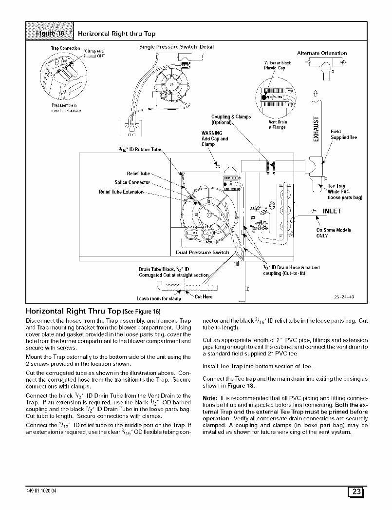
Horizontal Right Thru Top (SeeFigure16)Disconnect the hoses from the Trap assembly, and remove Trap
and Trap mounting bracket from the blower compartment. Usingcover plate and gasket provided in the loose parts bag, cover the
hole from the burner compartment to the blower compartment andsecure with screws.
Mount the Trap externally to the bottom side of the unit using the
2 screws provided in the location shown.
Cut the corrugated tube as shown in the illustration above. Con-nect the corrugated hose from the transition to the Trap. Secure
connections with clamps.
Connect the black 1/2" ID Drain Tube from the Vent Drain to theTrap. If an extension is required, use the black 1/2" og barbed
coupling and the black 1/2" ID Drain Tube in the loose parts bag.
Cut tube to length. Secure connections with clamps.
Connect the 3/16" ID relief tube to the middle port on the Trap. If
an extension is required, use the clear 3/16" OD flexible tubing con-
nector and the black 3/16" ID relief tube in the loose parts bag. Cut
tube to length.
Cut an appropriate length of 2" PVC pipe, fittings and extension
pipe long enough to exit the cabinet and connect the vent drain toa standard field supplied 2" PVC tee
Install Tee Trap into bottom section of Tee.
Connect the Tee trap and the main drain line exiting the casing as
shown in Figure 18.
Note: It is recommended that all PVC piping and fitting connec-tions be fit up and inspected before final cementing. Both the ex-
ternal Trap and the external Tee Trap must be primed beforeoperation. Verify all condensate drain connections are securely
clamped. A coupling and clamps (in loose part bag) may beinstalled as shown for future servicing of the vent system.
440O1102004 [_
HorizontalRight-SideVent
Single Pressure Switch Detail Yellowor black
SpliceConnector /
ReliefTube Extensionj_/
i
Dual Pressure Switc_
DrainTube Black, s/8" ID // (
Ct°[riugatedCut at _/
Leaveroomfor clam/ P _ Cut Here
VentDrain
&Clamps
Level or Slopedtowards Tee
N
_= /2" ID Dr =in
Elbow
o
\ Barbe0_ DrainHose
(Cut-to- fit)
Coupling &Clamps
ptional)
Fiel_liedTee
(looseparts bag)
On SomeModels
/ONLY
Alternate Orienation
coupling
25-24-50
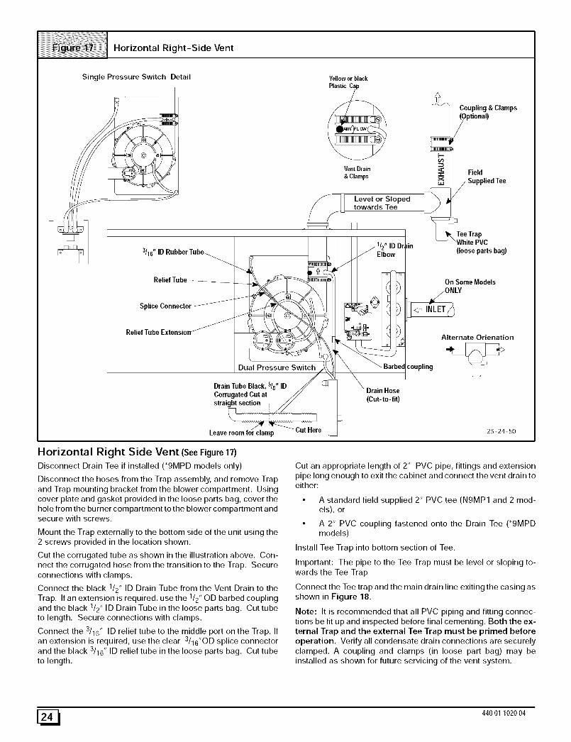
Horizontal Right Side Vent (SeeFigure 17)Disconnect Drain Tee if installed ('9MPD models only)
Disconnect the hoses from the Trap assembly, and remove Trapand Trap mounting bracket from the blower compartment. Using
cover plate and gasket provided in the loose parts bag, cover thehole from the burner compartment to the blower compartment andsecure with screws.
Mount the Trap externally to the bottom side of the unit using the2 screws provided in the location shown.
Cut the corrugated tube as shown in the illustration above. Con-
nect the corrugated hose from the transition to the Trap. Secureconnections with clamps.
Connect the black 1/2" ID Drain Tube from the Vent Drain to theTrap. If an extension is required, use the 1/2" OU barbed coupling
and the black 1/2" ID Drain Tube in the loose parts bag. Cut tubeto length. Secure connections with clamps.
Connect the 3/16" ID relief tube to the middle port on the Trap. Ifan extension is required, use the clear 3/16"OD splice connector
and the black 3/16" ID relief tube in the loose parts bag. Cut tubeto length.
Cut an appropriate length of 2" PVC pipe, fittings and extension
pipe long enough to exit the cabinet and connect the vent drain toeither:
• A standard field supplied 2" PVC tee (N9MP1 and 2 mod-els), or
• A 2" PVC coupling fastened onto the Drain Tee (*9MPDmodels)
Install Tee Trap into bottom section of Tee.
Important: The pipe to the Tee Trap must be level or sloping to-wards the Tee Trap
Connect the Tee trap and the main drain line exiting the casing asshown in Figure 18.
Note: It is recommended that all PVC piping and fitting connec-
tions be fit up and inspected before final cementing. Both the ex-ternal Trap and the external Tee Trap must be primed beforeoperation. Verify all condensate drain connections are securely
clamped. A coupling and clamps (in loose part bag) may beinstalled as shown for future servicing of the vent system.
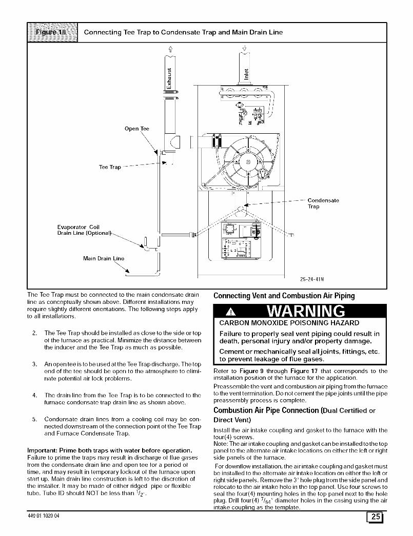
Connecting Tee Trap to Condensate Trap and Main Drain Line
Open Tee
\Tee Trap/_---_
Evaporator Coil
Drain Line (Optional)-.................._]_E
Main Drain Line
&
E B
,m o
o_ /
Condensate
Trap
25-24-41N
The Tee Trap must be connected to the main condensate drain
line as conceptually shown above. Different installations mayrequire slightly different orientations. The following steps applyto all installations.
2. The Tee Trap should be installed as close to the side or top
of the furnace as practical. Minimize the distance betweenthe inducer and the Tee Trap as much as possible.
3. An open tee is to be used at the Tee Trap discharge. The topend of the tee should be open to the atmosphere to elimi-
nate potential air lock problems.
4. The drain line from the Tee Trap is to be connected to thefurnace condensate trap drain line as shown above.
5. Condensate drain lines from a cooling coil may be con-nected downstream of the connection point of the Tee Trap
and Furnace Condensate Trap.
Important: Prime both traps with water before operation.Failure to prime the traps may result in discharge of flue gases
from the condensate drain line and open tee for a period oftime, and may result in temporary lockout of the furnace upon
start up. Main drain line construction is left to the discretion ofthe installer. It may be made of either ridged pipe or flexibletube. Tube ID should NOT be less than 1/2,,.
44001 102004
Connecting Vent and Combustion Air Piping
CARBON MONOXIDE POISONING HAZARD
Failure to properly seal vent piping could result indeath, personal injury and/or property damage.
Cement or mechanically seal all joints, fittings, etc.to prevent leakage of flue gases.
Refer to Figure 9 through Figure 17 that corresponds to theinstallation position of the furnace for the application.
Preassemble the vent and combustion air piping from the furnaceto the vent termination. Do not cement the pipe joints until the pipepreassembly process is complete.
Combustion Air Pipe Connection (Dual Certified orDirect Vent)
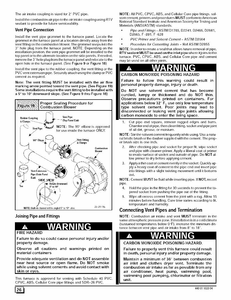
Install the air intake coupling and gasket to the furnace with thefour(4) screws.Note: The air intake cou piing and gasket ca n be installed to the toppanel to the alternate air intake locations on either the left or rightside panels of the furnace.
For downflow installation, the air intake coupling and gasket mustbe installed to the alternate air intake location on either the left or
right side panels. Remove the 3" hole plug from the side panel andrelocate to the air intake hole in the top panel. Use four screws toseal the four(4) mounting holes in the top panel next to the holeplug. Drill four(4) 7/64" diameter holes in the casing using the air
intake coupling as the template.
[!N
The air intake coupling is sized for 2" PVC pipe.
Install the combustion air pipe to the air intake coupling using RTVsealant to provide for future serviceability.
Vent Pipe Connection
Install the vent pipe grommet to the furnace panel. Locate the
grommet in the furnace panel at a location directly away from thevent fitting on the combustion blower. The grommet snaps into the3" hole plug from the furnace panel. NOTE: Depending on theinstallation position, the vent pipe grommet will be installed to the
top panel or to the alternate location on the side panels. If needed,remove the 3" hole plug from the furnace panel and relocate to theopen hole in the furnace panel. (See Figure 9 or Figure 18)
Install the vent pipe to the rubber coupling, the vent fitting or the
PVC vent extension pipe. Securely attach using the clamp or PVCcement as required.
Note: The vent fitting MUST be installed with the air flowmarking arrow pointed toward the vent pipe. (See Figure 19)Some installations require the vent fitting to be installed with
a 5 ° to 10 ° downward slope. (See Figure 9 thru Figure 18)
Proper Sealing Procedure forCombustion Blower
RubberCoupling _Vent Pipe
&Clamps'__ _(Top PanelExit)
VentPine t_ NOTE : The 90 ° elbow is approved
r for use inside the furnace ONLY.
NOTE: All PVC, CPVC, ABS, and Cellular Core pipe fittings, sol-vent cement, primers and procedures MUST conform to AmericanNational Standard Institute and American Society for Testing andMaterials (ANSI/ASTM) standards.
NOTE: In order to create a seal that allows future removal of pipe,RTV sealant MUST be used on the inlet pipe where it joins to thefurnace. PVC, CPVC, ABS, and Cellular Core pipe and cementmay be used on all other joints.
CARBON MONOXIDE POISONING HAZARD
Failure to follow this warning could result inpersonal property damage, injury or death.
Do NOT use solvent cement that has becomecurdled, lumpy or thickened and do NOT thin.Observe precautions printed on containers. Forapplications below 32 ° F., use only low temperaturetype solvent cement. Poor joints may lead todisconnected or leaking vent pipe joints allowingcarbon monoxide to enter the living space.
1. Cut pipe end square, remove ragged edges and burrs.Chamfer end of pipe, then clean fitting, socket and pipe jointof all dirt, grease, or moisture.
NOTE: Stir the solvent cement frequently while using. Use a natu-
90 ° Elbow& Clamps
Tee
Pipe (Side Panel
Exit)SIDE VIEW
wnward
NOTE: Built-in channel will be angled 5° to 10° also.
Joining Pipe and Fittings
FIRE HAZARD
CombustionBlower
25-24-14a
ral bristle brush or the dauber supplied with the cement. The prop-er brush size is one inch.
2. After checking pipe and socket for proper fit, wipe socketand pipe with cleaner-primer. Apply a liberal coat of primerto inside surface of socket and outside of pipe. Do NOT al-low primer to dry before applying cement.
3. Apply a thin coat of cement evenly in the socket. Quickly ap-ply a heavy coat of cement to the pipe end and insert pipeinto fittings with a slight twisting movement until it bottomsout.
NOTE: Cement MUST be fluid while inserting pipe. If NOT, recoatpipe.
4. Hold the pipe in the fitting for 30 seconds to prevent the ta-pered socket from pushing the pipe out of the fitting.
5. Wipe all excess cement from the joint with a rag. Allow 15minutes before handling. Cure time varies according to fit,temperature and humidity.
Connecting Vent Pipes and TerminationNOTE: Combustion air intake and vent MUST terminate in the
same atmospheric pressure zone. If installation is in a cold climate(sustained temperatures below O°F), increase the minimum dis-tance between vent pipe and air intake from 8" to 18".
Failure to do so could cause personal injury and/orproperty damage.
Observe all cautions and warnings printed onmaterial containers
Provide adequate ventilation and do NOT assemblenear heat source or open flame. Do NOT smokewhile using solvent cements and avoid contact with
skin or e,yes.
This furnace is approved for venting with Schedule 40 PVC,CPVC, ABS, Cellular Core pipe fittings and SDR-26 PVC.
CARBON MONOXIDE POISONING HAZARD.
Failure to properly vent this furnace could resultin death, personal injury and/or property damage.
Maintain a minimum of 36" between combustionair inlet and clothes dryer vent. Terminate thecombustion air intake as far as possible from anyair conditioner, heat pump, swimming pool,swimming pool pumping, chlorinator or filtrationunit.
[_ 440 01 1020 04
1, Install all couplings, nipples and elbows using proper proce-dures for Joining Pipe and Fittings and maintain spacingbetween vent and combustion air piping as indicated inFigure 20 through Figure 28.
MIN. _18" Minimumfor coldclimates
(substained below 0° F)
MIN.
GRADELEVEL 25-00-05FON
SNOW LEVEL
Horizontal Termination
1, Cut two holes. 21/2" for 2" pipe, 3" for 21/2" pipe, or 31/2" for
3" pipe. Do NOT make the holes oversized, or it will be nec-essary to add a sheet metal or plywood plate on the outsidewith the correct size hole in it.
2, Check hole sizes by making sure it is smaller than the cou-
plings or elbows that will be installed on the outside. Thecouplings or elbows MUST prevent the pipe from beingpushed back through the wall.
3. Extend vent pipe and combustion air pipe through the wall3/4" to 1" and seal area between pipe and wall.
4. Install the couplings, nipple and termination elbows asshown and maintain spacing between vent and combustionair piping as indicated in Figure 20 and Figure 21.
A metal shield is recommended 18" x 18" min. or 18" min. diameteraround the vent termination at the exterior wall to protect the houseexterior materials from flue product or condensation (freezing)damage.
Using Exterior Risers
1,
2.
3,
Install elbows and pipe to form riser as shown in Figure 21.
Secure vent pipe to wall with galvanized strap or other rustresistant material to restrain pipe from moving.
Insulate pipe with Armaflex or equivalent moisture resistantclosed cell foam insulation or Fiberglass insulation if boxedin and sealed against moisture.
........................................................................._!i i I Risers t° Get Ab°ve sn°w Level°rGradesidewallLeveITerminati°nwith Exterior
8" *
MIN. _ "18" Minimum for cold climates
20' (substained below 0° F)JW MAX
8"
MIN.
• GRADE LEVELOR
SNOW LEVEL 25-00-04F
Vertical Termination
1. Figure 22 shows the proper installation and clearances forvertical vent termination. The vertical roof termination
should be sealed with a plumbing roof boot or equivalentflashing. The inlet of the intake pipe and end of the exhaustvent must be terminated no less than 12" above the roof or
snow accumulation level, and 12" away from a vertical wallor other protrusion.
2. If the vent system is installed in an existing chimney makesure clearances shown in Figure 22 are maintained. Hori-zontal section before the termination elbow can be ex-
tended on the inlet air to provide necessary clearance.
Rooftop Termination
A =12"Aboveroofor snowaccumulationlevelB=8" Min.,20'Maximum,exceptinareaswithextremecoldtemperatures(sustainedbelow0°% the18"Min.
Vent Termination Shielding
Under certain wind conditions some building materials may be af-fected by flue products expelled in close proximity to unprotectedsurfaces. Sealing or shielding of the exposed surfaces with a cor-rosion resistant material (such as aluminum sheeting) may be re-quired to prevent staining or deterioration. The protective materialshould be attached and sealed (if necessary) to the building beforeattaching the vent terminal.
44001 102004 [_
Multi Vent Termination Clearances
When two (2) or more furnaces are vented near each other, each
furnace must be individually vented.
Two (2) vent terminations may be installed as shown in Figure 23,Figure 24, Figure 25, Figure 26, Figure 27 and Figure 28, butthe next vent termination must be at least 36" away from first 2 ter-minations. It is important that vent terminations be made as shownto avoid recirculation of flue gases.
I c°ncentric vent andc°mbusti°n-AirRoof Termination
12"Min. GradeoriSnow Level
CombustionAir
Dimension "A" is touching or 2" maximum separation.
Concentric Vent and Combustion-Air Sidewall Termination
ExhaustVent 25-22-02d
Dimension "A" is touching or 2" maximum separation.
Sidewall Inlet Vent and Exhaust-Air Termination
18"Min.forColdClimates(SustainedBelow0o F
12" Min. Grade or
Snow Level
FF_iDiDimension "A" is touchin9 or 2" maximum separation.
Sidewall Inlet Vent and Exhaust-AirTermination with Exterior Risers
18" Min. for Cold Climates_(SustainedBelow 0° F)
8" Min.
GradeorSnow Level
Dimension "A" is touchin9 or 2" maximum separation.iiiil
Rooftop Inlet Vent and Exhaust-Air Termination
18"Min.forColdClimates _ \ _-(SustainedBelow0° F)
8"Min.20'Max.
12" Min.
Level
/Exhaust
25-22-43
Recommended AlternateInstallation for SustainedCold Weather (-O ° F & below)
OVERHANGEXHAUST 12"MIN.
IN ET
Level
OR Snow Level
FRONT VIEW
Same Joist
Space
SIDE VIEW
25-23-73
440 01 1020 04
5. Gas Supply and Piping
CARBON MONOXIDE POISONING, FIRE ANDEXPLOSION HAZARD.
Failure to follow these instructions could result indeath, personal injury and/or property damage.
Models designated for Natural Gas are to be usedwith Natural Gas ONLY, unless properly converted touse with LP gas.
NOTE: The rating plate is stamped with the model number, gastype and gas input rating. In addition, models manufactured forsale in Canada have orifice size information stamped on the ratingplate.
Alternate BTUH Input Ratings (USA Only)
The input rating of these furnaces can be changed from the stan-dard input rating to the alternate input rating shown in Table 5, bychanging the main burner orifices. NOTE: The input rating ot80,000 BTUH models cannot be changed from the standard input.Changing of burner orifices MUST be done by a qualified servicetechnician. See section on changing orifices or following page.
IAIternate Input Ratings, USA ONLY.BTUH BTUH Natural LP
Standard Alternate Gas GasRating Rating Orifice Orifice
50,000 40,000 #44 #55
75,000 60,000 #44 #55
100,000 80,000 #44 #55
125,000 100,000 #44 #55
Supply Pressure
FIRE HAZARD
Failure to properly set input pressure could result indeath, personal injury and/or property damage.
Do NOT set input rating above that shown on ratingplate.
1. Supplypressurecanbecheckedusingthel/8 " NPTportonthe supply side of the gas valve.
2. Gas input to burners MUST NOT exceed the rated inputshown on rating plate.
3. Do NOT allow minimum gas supply pressure to vary down-ward. Doing so will decrease input to furnace. Refer toTable 6 for normal gas supply and manifold pressures.
Gas Supply Pressure
Gas supply pressure should be within minimum and maximum val-ues listed on rating plate. Pressures are usually set by gas suppli-ers.
Manifold Gas Pressure Adjustment
NOTE: Make adjustment to manifold pressure with burners oper-ating.
ELECTRICAL SHOCK HAZARD.
Failure to do so could result in death, personalinjury and/or property damage.
Turn OFF power to furnace before changing speedtaps.
1. Remove the burner compartment door.
2. With gas OFF, connect manometer to tapped opening ongas valve. Use manometer with a 0 to 15" water column
range.
3. Turn gas ON. Operate the furnace by using a jumper wire onthe R to W thermostat connections on the fan board.
4. Remove manifold pressure adjustment screw cover on fur-nace gas control valve. Turn adjusting screw counterclock-wise to decrease manifold pressure and clockwise toincrease pressure.
NOTE: Adjustment screw cover MUST be replaced on gas controlvalve before reading manifold pressure and operating furnace.
5. Set manifold pressure to value shown in Table 6, Table 7,Table 8 or Table 9.
6. When the manifold pressure is properly set, replace the ad-justment screw cover on the gas control valve.
7. Remove jumper wire from thermostat connection on fanboard. Remove manometer connection from manifold
pressure tap, and replace plug in manifold.
8. Check for leaks at plug.
9. Replace the burner compartment door.
44001 102004 [_
MANIFOLDPRESSUREAND ORIFICESIZE FORHIGHALTITUDEAPPLICATIONSiiiiiiiii_ ii_!!!!!!! i
NATURAL GAS MANIFOLD PRESSURE (" w.c.)..............................................................FOR THE 50,000, 75,000, 100,000 and 125,000 BTUH MODELS
MEAN ELEVATION FEET ABOVE SEA LEVELHEATING
0 to 2001 to 3001 to 4001 to 5001 to 6001 to 7001 toVALUE2000 3000 4000 5000 6000 7000 8000
NOTE: Natural gas data is based on 0.60 specific gravity. For fuels with different specific gravity consult the National Fuel Gas Code ANSIZ223.1-2002/NFPA 54-2002 or National Standard of Canada, Natural Gas And Propane Installation Code CSA B149.1-00.
Ta_i CPG or PROPANE GAS MANIFOLD PRESSURE (" w.c.)................................................................................................................FOR THE 50,000, 75,000, 100,000 and 125,000 BTUH MODELS
HEATING VALUE MEAN ELEVATION FEET ABOVE SEA LEVEL
at ALTITUDE 0 to 2001 to 3001 to 4001 to 5001 to 6001 to 7001 toBTU/CU, FT. 2000 3000 4000 5000 6000 7000 8000
2500 10.0 10.0 9.0 10.0 9.4 8.5 10.0
Orifice Size #54 #54 #54 #55 #55 #55
NOTE: Propane data isbased on 1.53 specific gravity. For fuels with different specific gravity consult the National Fuel Gas Code ANSI Z223.1-2002/N FPA
54-2002 or National Standard Of Canada, Natural Gas And Propane Installation Code CSA B149.1-00.
NATURAL GAS MANIFOLD PRESSURE (" w.c.)..............................................................FOR THE 80,000 BTUH MODELS
MEAN ELEVATION FEET ABOVE SEA LEVELHEATING
0 to 2001 to 3001 to 4001 to 5001 to 6001 to 7001 toVALUE
NOTE: Natural gas data is based on 0.60 specific gravity. For fuels with different specific gravity consult the National Fuel Gas Code ANSIZ223.1-2002/NFPA 54-2002 or National Standard of Canada, Natural Gas And Propane Installation Code CSA B149.1-00.
440 01 1020 04
iiiiiiiiiiiiiiiiiiiiiiiiiiiiiiiiiiiiiiiiiiiiiiiiiiiiiiiiiiiiiiiiiiiiiiiii_i_;!!_;_;:_;_;_!!!i!i!i!i!i!i!i!i_i_¸_;_!_i!_!i_iiiiiiiiiiiiiiii_iiiiiiiiiiii_iiiiiiiiiiiiiiiiiiiiiiiiiiiiiiiiiiiiiiiiiiiiiiiiiiiiiiiiiiiiiiiiiiiiiiiiiiiiiiiiiiiiiiiii_i;iiiiiiiiiiiiiiiiiiiiiiiiiiiiiiiiiiiiiiiiiiiiiiiiiiiiiiiiiiiiiiiiiiiiiiiiiii i ii ili ii i!
HEATING VALUEat ALTITUDEBTU/CU, FT.
2500
Orifice Size
LPG or PROPANE GAS MANIFOLD PRESSURE (" w.c.)FOR THE 80,000 BTUH MODELS
MEAN ELEVATION FEET ABOVE SEA LEVEL0 to 2001 to 3001 to 4001 to 5001 to2000 3000 4000 5000 600010.0 8.9 8.4 10.0 10.0
#55 #55 #55
6001 to 7001 to
7000 8000
10.0 10.0
NOTE: Propane data isbased on 1.53 specific gravity. For fuels with different specific gravity consult the National Fuel Gas Code ANSI Z223.1-2002/N FPA
54-2002 or National Standard Of Canada, Natural Gas And Propane Installation Code CSA B149.1-00.
NOTE: The derating of these furnaces at 2% (Natural Gas) and Changing Orifices for High Altitude4% (Propane Gas) has been tested and design-certified by CSA.
General Derating Rules
1, These furnaces may be used at full input rating wheninstalled at altitudes up to 2,000'. When installed above
2,000', the input must be decreased 2% (natural) or 4% (LP)for each 1000' above sea level. See Table 10 for requiredhigh altitude input rate.
High Altitude Input Rate =Nameplate Sea Level Input Rate x (Multiplier)
Elevation
2001'-3000'
3001'-4000'
4001'-5000'
5001'-6000'
6001'-7000'
7001'-8000'
High Altitude Multiplier
Natural Gas
0.95
0.93
0.91
0.89
0.87
0.85
LP Gas
0.90
0.86
0.82
0.78
0.74
0.70
Based on mid-range of elevation.
2. For operation with natural gas at altitudes above 2,000', ori-fice change and/or manifold pressure adjustments may berequired for the gas supplied. First consult your local gas
supplier, then refer to Table 6 (50,000, 75,000, 100,000and 125,000 BTU H models) or Table 8 (80,000 BTUH mod-
els) for required pressure change and/or orifice change forhigh altitudes.
3, For operation with LP gas, gas orifices MUST be changed
and manifold pressure MUST be maintained as per Table 7(50,000, 75,000,100,000 and 125,000 BTUH models) orTable 9 (80,000 BTUH models). Orifices can be ordered
through our distributor. (See Figure 29)
4. In cases where Table 6, Table 7, Table 8 or Table 9 is not
applicable, eg. alternate input rate application, refer to
Table 10 for required high altitude input rate.
High Altitude Air Pressure Switch
Altitudes over 4,000' may require a different air pressure switchthan the one installed at the factory. Check parts list for pressure
switch and consult your distributor for part number and availability.In Canada, provincial codes may govern installation of switch.Check with governing authorities.
ELECTRICAL SHOCK, FIRE OR EXPLOSIONHAZARD
Failure to properly install orifices could result indeath, personal injury and/or property damage.
Turn OFF electric power (at disconnect) and gassupply (at manual valve in gas line) when installingorifices. Installation of orifices requires a qualifiedservice technician.
NOTE: Main burner orifices can be changed for high altitudes.
1. Disconnect gas line from gas valve.2. Remove manifold from furnace.
3. Remove the orifices from the manifold and replace themwith properly sized orifices.
4. Tighten orifices so it is seated and gas tight. (SeeFigure 29)
Measure from face of orificeto the back side of themanifold,
Natural Gas Input Rating CheckNOTE: The gas meter can be used to measure input to furnace.Rating is based on a natural gas BTU content of 1,000 BTU's percubic meter. Check with gas supplier for actual BTU content.
1. Make sure burner compartment door is in place before per-forming the following steps.
2. Turn OFF gas supply to all appliances and start furnace.
Typica,GasPipiog,orU .owDrip Legand Union,Union* shouldbeoutside the Gas Pipe Grommet(SinglePipe)
cabinet.Manualshut-off valveMUST be upstreamof "_ _Y / _//_
dripleg,union, andfurnace. Manualshut-off
Use elbows and3" pipenippleto connectvalveto _
on some models. . / \ /_ _ \ /
have 1 or 2
I Typical Gas Piping for Downflow
Use elbows and 3" pipe nipple to connect valveto piping when using left side gas pipe
LP Low pressureswitch. Optional LPconversion.
Manualshut- offvalve
Drip Leg and Union, Union* should bethe cabinet. Manual shut-off valve MUST be
upstream of dripleg, union, and furnace.Gas Pipe Grommet
*Union may be installed inside the cabinet when necessary (Single Pipe)because of clearances.
4odels may have1 or 2 pressureswitches
25-23-39
Gas Piping Requirements
NOTE: The gas supply line must be installed bya qualified servicetechnician in accordance with all building codes, (In the state ofMassachusetts, gas supply connections MUST be performed by alicensed plumber or gas fitter).
1. Properly size gas pipe to handle combined appliance load
or run gas pipe directly from gas meter or LP gas regulator.Refer to NFGC and ANSI Z223.1 for proper gas pipe size.
2. Install correct pipe size for run length and furnace rating.
3. Measure pipe length from gas meter or LP second stageregulator.
Failure to properly install metal gas connectorcould result in death, bodily injury and/or propertydamage.
A flexible corrugated metal gas connector must beproperly installed, shall not extend through the sideof the furnace,and shall not be used inside thefurnace.
Black iron pipe shall be installed at the furnace gascontrol valve and extend a minimum of 2" outsidefurnace casing.
4. Use black iron or steel pipe and fittings or other pipe ap-proved by local code.
NOTE: The use of copper tubing for gas piping is NOT approvedby the state of Massachusetts.
5. Use ground joint unions and install a drip leg no less than 3"
long to trap dirt and moisture before it can enter gas valve.
6. Use two pipe wrenches when making connections to pre-vent gas valve from turning.
7. Install a manual shut-off valve external to furnace casing
and tighten all joints securely.
Additional LP Connection Requirements
1. Have a licensed LP gas dealer make all connections at stor-age tank and check all connections from tank to furnace.
2. If copper tubing is used, it MUST comply with limitation set inNational Fuel Gas Code or CGA codes.
3. Two-stage regulation of LP gas is recommended.
Final Check
3.
4.
5.
The furnace and the gas valve must be disconnected from thegas supply piping system during any pressure testing of thatsystem at test pressures in excess of 1/2" PSIG. Close themanual shut-off valve before testing at such pressures.
When installation is complete, test all pipe connections for1 ,leaks with the gas pressure less than /2' PSIG to the gas
valve.
Apply a commercial soap solution to all joints to test forleaks. Correct any leaks indicated by bubbles.
Correct even the smallest leak at once.
Check for leaks at gas valve and orifice connections to theburner manifold along with the pilot tube connections to the
valve and pilot assembly while the furnace is operating.
6. Electrical Wiring
ELECTRICALSHOCK HAZARD.
Failure to do so could result in death, personalinjury and/or property damage.
Turn OFF electrical power at fuse box or servicepanel before making any electrical connectionsand ensure a proper ground connection is madebefore connecting line voltage.
Power SupplyWiring
The furnace MUST be electrically wired and grounded in accor-dance with local codes, or in the absence of local codes with thelatest edition of The National Electric Code, ANSI N FPA 70 and/orThe Canadian Electric Code CSA C22.1.
The power supply to the furnace connections must be between104 VAC and 127 VAC during furnace operation for acceptableperformance.
Field wiring connections must be made inside the furnace connec-tion box. A suitable strain relief should be used at the point thewires exit the furnace casing.
I Copper conductors shall be used. Line voltage wires should
conform to temperature limitation of 63 ° F (35 ° C) rise and be sizedfor the unit maximum amps stated on the rating plate. Add the full
load amps for potential field-installed accessories such as elec-tronic air cleaners and humidifiers that would receive power fromthe furnace control. The furnace control is rated for a maximum of
0.8 amps combined for EAC and Hum. Consult N EC or local codesfor proper wire and circuit sizing.
J- Box Relocation
The j-box is installed on left side of casing. An alternate j-boxlocation on right side can be used.
1. Remove bag containing two hole plugs and two self tappingscrews from loose parts bag in blower compartment.
2. Remove two screws holding j-box to casing.
3. Move large hole plug from right to left j-box location.
4. Move j-box to alternate location and attach using two selftapping screws from bag.
5. Apply two hole plugs from bag at left j-box location.
Thermostat
Thermostat location has an important effect on the operation of theunit. Follow instructions included with thermostat for correct
mounting and wiring.
Low voltage connections to furnace must be made on terminalboard to fan control.
Set thermostat heat anticipator in accordance with the TechnicalSupport Manual.
Optional Equipment
All wiring from furnace to optional equipment MUST conform to lo-cal codes or, in the absence of local codes with the latest edition ofThe National Electric Code, ANSI NFPA 70 and/or The Canadian
Electric Code CSA C22.1. Install wiring in accordance withmanufacturer's instructions. The wiring MUST have a minimumtemperature rating of 105 ° C.
Humidifier/Electronic Air CleanerThe furnace is wired for humidifier and/or electronic air cleaner
connection.
440O1102004 E_
REDUCED FURNACELIFE HAZARD
Failure to follow caution instructions may result inreduced furnace life.
Do NOT exceed 115V/0.8 amp. maximum currentload for both the EAC terminal and the HUMterminal combined.
NOTE: The humidifier will be powered when the furnace is firedand the circulating air blower comes on. The electronic air cleanerwill be powered anytime the air circulating blower is energized.However, the electronic air cleaner is NOT energized during con-tinuous fan operation controlled by the electronic fan control.
Fan Control
The fan control is preset at the factory with a fixed blower ON delayof 30 seconds in the heating mode. The blower OFF timing is pre-set at 140 seconds. If desired, the fan OFF delay can be reset toobtain the longest delay times while still maintaining comfort lev-els. See "Furnace Wiring Diagram".
Fan Delay DIP Switch Settings
12
60SEC 100 SEC
COOL ON DELAY: 5 SEC,COOL OFF DELAY: 90 SEC.HEAT ON DELAY: 30 SEC.
Permissible limits of voltage at which unit will operate satisfactorily
Control Center Fuse
The 24V circuit contains a 5-amp, automotive-type fuse locatedon fan timer board. (See Figure 33) Any electrical shorts of 24Vwiring during installation, service, or maintenance may cause fuseto blow. If fuse replacement is required, use only a fuse of identicalsize (5 amp.)
Fan Timer Connections
FUSE/'_r
25-23-41
[_ 440 01 1020 04
7. Ductwork and Filter
CARBON MONOXIDE POISONING HAZARD.
Failure to properly seal duct could result in deathand/or personal injury.
Do NOT draw return air from inside a closet or utilityroom where furnace is located. Return air ductMUST be sealed to furnace casing.
Installation
NOTE: Design and install air distribution system to comply with AirConditioning Contractors of Arnerica manuals andlor NFPA pam-phlets 90A and 90B or other approved methods that conform to lo-cal codes and good trade practices.
I. When furnace supply ducts carry air outside furnace area,seal return air duct to furnace casing and terminate duct out-side furnace space.
2. Install air conditioning cooling coil (evaporator) on outletside of furnace.
3. For furnaces installed without a cooling coil it is recom-mended that the outlet duct be provided with a removable
access panel. This panel should be accessible when thefurnace is installed so the exterior of the heat exchanger canbe viewed for inspections. The access panel MUST besealed to prevent leaks.
4. If separate evaporator and blower units are used, installgood sealing dampers for air flow control. Chilled air goingthrough the furnace could cause condensation and shortenthe furnace life.
NOTE: Dampers (field supplied) can be either automatic or manu-al. Manually operated dampers MUST be equipped with a meansto prevent furnace or air conditioning operation unless da roper is inthe full heat or cool position.
CARBON MONOXIDE POISONING HAZARD.
Failure to follow this warning could result in death,personal injury and/or property damage.
Cool air passing over heat exchanger can causecondensate to form resulting in heat exchangerfailure.
Connections
NOTE: On upflow installations, return air can enter through eitherside, both sides, or the bottom. On horizontal or downflow installa-
tions the return air must enter through the knockout opening in thelower panel of the furnace. Return air can not enter through rear ofthe furnace. When the furnace is located in an area near or adja-cent to the living area, the system should be carefully designedwith returns to minimize noise transmission through the returngrille. Any blower moving a high volume of air will produce audiblenoise which could be obJectionable to when the unit is located veryclose to living areas. It is advisable to route the return air ducts un-
der the floor or through the attic.
I. For side connections using a 16" x 25" filter, cut out the em-bossed area shown in Figure 34. This will provide a 14112,, x22112 ,, approximate opening.
Side Return Air Cutout
= Height of Cutout for 16" x 25" Filter
AB 22112"141/2"Width of Cutout for 16" x 25" Filter _ rll
Embossed Areaon Side of Furnace j_-
_'_ Furnace
" Bottom
NOTE: Furnaces with 5 TONS cooling rating require two(2) sidereturns or one side return with bottom return.
2. Bottom returns can be made by removing the knockout pan-el in the furnace base. Do NOT remove knock-out except fora bottom return.
3. Installation of locking-type dampers are recommended in allbranches, or in individual ducts to balance system's air flow.
4. Non-combustible, flexible duct connectors are recom-
mended for return and supply connections to furnace.
5. If air return grille is located close to the fan inlet, install atleast one, 90 ° air turn between fan and inlet grille to reducenoise.
NOTE: To further reduce noise, install acoustical air turning vanesand/or line the inside of duct with acoustical material.
SizingExisting or new ductwork MUST be sized to handle the correct
amount of airflow for either heating only or heating and air condi-tioning.
Insulation
1. Insulate ductwork installed in attics or other areas exposed
to outside temperatures with a minimum of 2" insulation andvapor barrier.
2. Insulate ductwork in indoor unconditioned areas with a mini-
mum of 1" insulation with indoor type vapor barrier.
Filters
A Filter must be used:
Filters are not supplied with these furnaces, but can be purchasedfrom dealer.
Use either filter type:
• Washable, high velocity filters are based on a maximum
air flow rating of 600 FPM.
• Disposable, Iowvelocity filters are based on a maximumair flow of 300 FPM when used with filter grille.
NOTE: Disposable, low velocity filters may be replaced with wash-able, high velocity filter providing they meet the minimum sizeareas. Washable, high velocity filters can be replaced ONLY withsame type and size.
44001 102004 E_
Mounted Filter Rack
25-20-90
Filter Installation using Optional Filter RackWhen installing or removing a bottom mounted filter, slide the twoside filter clips to the back of the furnace BEFORE installing or re-moving. This will allow the filter to clear the front raised edge of thefurnace. Insert filter into side clips first and push filter back until it isfully engaged into back clip. When filter is in place, slide clips backinto place midway on filter as shown in Figure 36.
Bottom Mounted Filter Rack
25-24-18
Slide filter clips towards back before removing
Refer to Figure 37 and for guidelines to install filters. Furnaceswhich require larger filter media and have limited clearances onone side of furnace, require a standoff filter rack, see Figure 37,available from your distributor.
Standoff Filter Rack
UsingOptionalStandoff FilterRack
25-21-45a
CAUTION
If filters are only suitable for heating application, advisehomeowner that filter size may need to be increased if airconditioning is added.
Addition Of Air Conditioning
When a refrigeration coil is used in conjunction with this unit, itmust be installed on the discharge side of the unit to avoid con-densation on the heat exchanger. The coil installation instructionsmust be consulted for proper coil location and installation proce-dures. With a parallel flow arrangement, dampers must beinstalled to prevent chilled air from entering the furnace. If ma nual-ly operated dampers are used, they must be equipped with ameans to prevent operation of either unit unless the damper is infull heat or full cool position.
A 3" clearance is required on the right side ofthe furnace in order torun the condensate drain line. Copper, iron or plastic tubing may beused for the condensate drain line.
Downflow Furnace Installation
Non- Combustible Floor Installation
Fabricate a plenum to the dimensions given in Table 11, for the fur-nace outlet. Plenum should be flanged, approximately 3/4" for sup-port.
Note: The three(3) screws in the top panel of the furnace next tothe duct flange MUST be removed to provide serviceability of theprimary heat exchangers in the downflow installation
1. Position plenum through the floor and set the furnace overthe opening in the floor. If necessary, grout around the baseto seal air leaks between the base and the floor.
Combustible Floor Installation
FIRE HAZARD
Failure to install unit on noncombustible subbase
could result in death, personal injury and/or
property damage.
Place furnace on noncombustible subbase on
downflow applications, unless installing on non-
combustible floorinq.
;ubbase for Combustible Floor
NOTE: The three(3) screws in the top panel of the furnace next tothe duct flange MUST be removed to provide serviceability of theprimary heat exchangers in the downflow installation
Note: When using the subbase for combustible floors, the dis-charge air duct flanges on the furnace MUST be broken down toprovide proper fit up to the subbase. Use duct pliers to bend theduct flanges flat onto the furnace casing. DO NOT bend the ductflanges inward (toward the heat exchangers) as air flow restric-tions may occur.
The Subbase for Combustible Floors MUST be used when a
downflow furnace is set on a combustible floor, even when the fur-nace is installed on a coil box.
1. Cut the opening in the floor according to Table 11. The holein the floor must be cut to the dimensions listed in Table 11
since the base is equipped with locating tabs that center thebase over the opening.
The opening in the base is 11/4 ', shorter and 11/8', narrower thanthe recommended size of the opening in the floor. This is done tomaintain clearance between the floor and the plenum.
2. Fabricate the plenum to the dimensions given in Table 11.Note that the dimensions given are outside dimensions.
[_ 440 01 1020 04
SubbasesforCombustibleFloorsDimensions
SubbaseforCombustibleFloorDimensions
H* J* K**
1511/16 283/4 149/16 16
195/16 283/4 183/16 16
22_/16 28J/4 2113/16 16
243/4 283/4 239/16 161/4
1511/16 209/16 149/16 161/4
195/16 209/16 183/16 161/4
23 209/16 2113/16 161/4
2411/15 209/15 239/15 16
Set the base over the opening in the floor, centering it over
the opening. Fasten the base to the floor with screws or
nails. See Figure 38, Figure 39 and Figure 40.
Subbase for CombustibleFloors Part Number
Furnace Subbase
NAHH001SB
NAHH002SB
NAHH003SB
NAHH010SB
Subbase for Coil Cabinets
NAHH004SB
NAHH005SB
NAHH006SB
NAHH009SB
Outside Dimension
_* Base Spacer Side To Side
3.
4. Drop the plenum through the opening in the base. The
flange of the plenum should rest on top of the subbase.
5. Position furnace or coil cabinet and furnace on subbase so it
This subbase for combustible floors has been designed so that theheight of the subbase raises the downflow coil off the floor to alloweasy installation of the condensate drain. See Figure 41.
440O1102004 E_
Condensate Line Raised by Base
25-20-52
8. Checks and Adjustments
Adjust Pilot Burner
FIRE OR EXPLOSION HAZARD.
Failure to turn OFF gas at shut off beforeconnecting manometer could result in death,personal injury and/or property damage.
Turn OFF gas at shut off before connectingmanometer.
StartupNOTE: Refer to the start-up procedures in the "User's InformationManual' or to the "Operating Instructions Label' on the furnace.
FIRE OR EXPLOSION HAZARD.
Failure to correct hazard could result in death,personal injury, and/or property damage.
If any sparks, odors or unusual noises occur,immediately shut OFF power to furnace. Check forwiring errors or obstruction to blower.
Gas SupplyPressureGas supply pressure should be within minimum and maximum val-ues listed on rating plate. Pressures are usually set by gas suppli-ers.
Manifold Gas Pressure AdjustmentNOTE: Make adjustment to manifold pressure with burners oper-ating.
1.
2.
3.
Remove the burner compartment door.
With gas OFF, connect manometer to tapped opening on
gas valve. Use manometer with a 0 to 15" water columnrange.
Turn gas ON and remove adjustment screw cover on gasvalve. Turn counterclockwise to decrease pressure andclockwise to increase.
4. For altitudes up to 2000', set pressure to value shown inTable 6 or Table 8, _+0.3" (8ram) water column. For alti-
tudes of 2000' to 8000', see Section 5 for correct pressuresetting.
The furnace has a pilot flame to light the main burner. The flame3 1should surround /8' to /2' of the flame sensor. See Figure 42. Toadjust, remove cap from pilot adjusting screw on gas valve. Turnscrew counterclockwise to increase or clockwise to decrease
flame as required. Replace adjusting screw cap.
Proper Flame
Adjustment
Pilot Burner
3/8" to 1/2"
Hot SurfaceIgniter
10-11-65
Main Burner Flame Check
Allow the furnaceto run approximately 10 minutes then inspect themain burner and pilot flames. See Figure 43.
Check for the following (Figure 43):
• Stable and blue flames. Dust may cause orange tips orwisps of yellow, but flames MUST NOT have solid, yellowtips.
• Flames extending directly from burner into heat ex-changer.
• Flames do NOT touch sides of heat exchanger.
If any problems with main burner flames are noted, it may be nec-essary to adjust gas pressures, or check for drafts.
[_ 440 01 1020 04
Main Burner
Face
10-10-78
Temperature Rise Check
The blower speed MUST be set to give the correct air temperaturerise through the furnace as marked on the rating plate. Tempera-ture rise is the difference between supply and return air tempera-tures.
To check temperature rise,use the following procedure:
1. Place thermometers in supply and return air registers asclose to furnace as possible, avoiding direct radiant heatfrom heat exchangers.
2. Operate furnace continuously for 15 minutes with all regis-
ters and duct dampers open.
3. Take reading and compare with range specified on ratingplate.
4. If the correct amount of temperature rise is NOT obtained, it
may be necessary to change blower speed. A higher blowerspeed will lower the temperature rise. A lower blower speedwill increase the temperature rise.
Changing Blower Speed
ELECTRICAL SHOCK HAZARD
Failure to do so could result in death and/or
personal injury.
Turn OFF power to furnace before changing
speed taps.
NOTE: The speed taps that the manufacturer sets from the factoryfor this product are based on a nominal 400 CFM per ton coolingand the basic mid range on the temperature rise for heating.
Since the manufacturer cannot establish the static pressurethat will be applied to the unit, it is the responsibility of the in-staller dealer/contractor to select the proper speed taps for theapplication when the unit is installed.
REDUCED FURNACE LIFE HAZARD
Failure to properly set the air temperature rise mayresult in reduced furnace life.
Use ONLY the following blower motor speed taps forsetting air temperature rise.
Blower Motor Speed Taps Model SizesHi (BLK) AllMed-Hi (O) All except 050F/J14Med Lo (BL All except 075B/F12
and 100F/J14
Lo (RED) 050B/F12,100J20,and 125J/L20
If it is necessary to change speeds, refer to steps below.
Refer to Furnace WMng Diagramfor location of the heatingand cooling speed taps located on the electronic fan controlas well as location of unused blower motor speed leads.Use the chart (Table 12) to determine the blower motor
speed settings.
Blower Speed Chart
Wire Color
Black
Orange*Blue
Red
Motor Speed
High
Med-HighMedium
Low
* Med-High speed may not be provided on all models.
Change the heat or cool blower motor speed by removingthe motor lead from the "Heat" or "Cool" terminal and re-
place it with the desired motor speed lead from the "Un-used Motor Lead" location. Connect the wire previouslyremoved from the "Heat" or "coor' terminal to the vacated
"Unused Motor Lead" terminal.
If the same speed must be used for both heating and cool-ing, remove the undesired motor speed lead from the"Heat" or "Cool" terminal and connect that lead to the openterminal at "Unused Motor Lead" location. Attach a jumperbetween the "Heat" and "Cool" terminals and the remainingmotor speed lead.
Note: For motors with (4) speed leads, it will be necessarytotape off the terminal of the motor speed lead removed fromthe "Heat" or "coor' terminal with electrical tape since anopen terminal will not be available at the "Unused MotorLead" location.
Continuous Fan Operation
A terminal is provided on the electronic fan control located in thecirculating blower compartment for operation of the continuous fanoption. This connection is intended for the low speed motor tap,and has a lower contact rating (8 amps) than the heat and cooltaps. When the low speed blower lead is connected to this termi-nal, this will provide low speed blower operation whenever the oth-er two speeds (Heat or Cool) are not energized.
Thoroughly check the system after modification to ensure theproper operation of the circulating air blower in all modes of opera-tion.
Separate speed selections for Heat, Cool, andContinuous Fan
Connect low speed lead from circulating motor to the "Cont." ter-minal at the electronic fan control. The appropriate motor leadsshould already be connected to the "Heat" and "coor' terminals.
Heating andContinuous BlowerSpeed theSame
If it is necessary to operate the heating speed and continuousblower speed using the same blower speed, connect a jumper be-tween the "Heat" and "Cont." terminals on the electronic fan con-trol.
Note: There should be only ONE motor lead going to the "Heat"and "Cont." terminals.
44001 102004 E_
9. Furnace Maintenance
FIRE, EXPLOSION, OR CARBON MONOXIDEHAZARDS
Failure to have the furnace inspected andmaintained could result in fire, explosion, or carbonmonoxide poisoning.
It is recommended that the furnace be inspectedand serviced on an annual basis (before the heatingseason) by a qualified service technician.
ELECTRICAL SHOCK, FIRE OR EXPLOSIONHAZARD
Failure to follow safety warnings exactly could resultin dangerous operation, serious injury, death orproperty damage.
Improper servicing could result in dangerousoperation, serious injury, death or property damage.
• Before servicing, disconnect all electrical powerto furnace.
• When servicing controls, label all wires prior todisconnecting. Reconnect wires correctly.
• Verify proper operation after servicing.
See "User's Information Manual" and the "Service Manual".
[_ 440 01 1020 04
10. Sequence of Operation & DiagnosticsThe following is the normal operating sequence for the control system.
Cooling (¥) Request:24 VAC signals applied to Y & G terminals of EFT (electronic fan timer) control.
• Cool motor speed energized after 5 second Cool Fan On Delay time.
Y & G signals removed from EFT.
• Cool motor speed de-energized after 90 second Cool Fan Off Delay time.
Circulating Fan (G) Request:24 VAC signals applied to G terminals of EFT control.
• Heat motor speed energized without delay.
G signal removed from EFT.
• Heat motor speed de-energized without delay.
Heating (W) Request:
24 VAC signals applied to W terminal of EFT control.• Inducer motor turns on.
• The gas valve solenoid energizes.
• Following a 3 second prepurge delay, the pilot valve opens and the ignitor begins to warm up.
• After the pilot lights, the main burners energize and light.
• Timed from the opening of the main gas valve, the control will delay 30 seconds before switching the fan to Heat speed.
W signal removed from EFT.
• The gas valve de-energizes and the main burners go out.
• The inducer runs at its present speed for a 30 second postpurge period.
• Timed from the gas valve de-energizing, the Heat fan speed de-energizes after the selected Heat Fan Delay time expires.
Heating Request with Gas Supply Line Shut Off:24 VAC signals applied to W terminal of EFT control.• Inducer motor turns on.
• The gas valve solenoid energizes.
• Following a 3 second prepurge delay, the pilot valve opens and the ignitor begins to warm up.
• The ignitor glows red-hot for 30 seconds, then turns off.
• The igniter stays off for 25 seconds, then begins to warm-up again.
• The igniter glows red-hot for 30 seconds, then turns off.
• The pilot valve closes 3 seconds after the igniter de-energizes.
• The inducer de-energizes 5 seconds after the pilot valve closes.
• The SmartValve proceeds to soft lockout and flashes error code 6.
• The control exits soft lockout after 5 minutes and begins
another ignition sequence.
44001 102004 [_
Gas Valve Diagnostic Codes (See Figure 44)OFF = Control not powered
Heartbeat = Normal Operation (Standby or call for heat)1 Flash = Not used
2 Flashes = Pressure switch closed when should be open
3 Flashes = Pressure switch circuit was still sensed as open 30 seconds after the inducer was energized. System is
in 5 minute delay mode, with inducer off. After 5-minute delay, a new ignition sequence will be initiated.
(Note: SV9541M On/Off switch in off position during a call for heat will generate this diagnostic code)
4 Flashes = Limit switch string open
5 Flashes = Flame sensed out of sequence - Flame signal still present.
6 Flashes + 1 Note 1 = Soft Lockout -Maximum retry count exceeded (failed to light within 4 trials for ignition)
6 Flashes + 2 Notes 1,2 = Soft Lockout -Maximum recycle count exceeded - Last failure was Flame Sense Lost During Run
6 Flashes + 3 Notes 1,2 = Soft Lockout -Maximum recycle count exceeded - Last failure was Airflow Proving Circuit Opened
During Run
6 Flashes + 4 Notes 1,2 = Soft Lockout -Maximum recycle count exceeded - Last failure was Limit Circuit Opened During Run
7 Flashes = Soft Lockout Due to Limit Trips Taking Longer than 2 minutes to Reset; Auto Reset After 1 Hour if
Call for Heat Still Present. Reset by Cycling Call for Heat at Any Time.
NOTE 1 : The 6 + X designation indicates a combination of flash codes: 6 flashes shows the control is in soft lockout, followed by X flashes
to indicate the reason the control went into soft lockout. When the 6+ X code is flashing, the SV9541 will attempt a new ignition sequence
after a five minute delay period, if the call for heat is still present. Reset of the thermostat will initiate a new ignition sequence immediately.
NOTE 2: Any combination of 5 'abnormal' events during a single call for heat will result in soft lockout. An 'abnormal' event is a Flame
Sense Failure During Run, Airflow Proving Circuit Open During Run, or Limit Circuit Open During Run. The flash code will indicate which
was the last 'abnormal' event that put the system into the soft lockout state based on the table above.
Typical Gas Valve Honeywell
OUTLET
PilotPressure
A_ustment(Hidden)
On\Off
INLET
Diagnostic Light
Manifold Pressure
Adjustment
dwg 25-23-31a
[_ 440 01 1020 04
HONEYWELL SV9541M "SMART VALVE" Sequence of Operation
I POWERAPPLIEDTO APPUANCE l
I THERMOSTAT CALLS FOR HEAT
¢I PRESSURESWITCHESPROVEDOPEN?i
I COMBUSTIONBLOWER ENERGIZEDI
PRESSURESWITCHESCLOSEDWITHIN30 SEC-ONDS?
3SECONDPRE-PURGE
PILOTVALVEOPENS:IGNITORPOWERED(1)
PILOT LIGHTSAND FLAMEIS SENSED I_uIDURING90 SECONDTRAILFORIGNITION?
FLAME SENSE LOST MORE THAN FIVE ITIMESINTHISCALL FOR HEAT? J--
NO
YES
J
I CIRCULATINGBLOWEROFF AFTER DELAY I
+COMBUSTIONAIR BLOWER OFF AFTERPOSTPURGE
(1) Ignitor "ON" for first 30 seconds of trial for ignition,then "OFF" for next 30 seconds. If the pilot hasnotlit, it turns back"ON" for the final 30seconds. The pilot valve remains energizedduring the entire90 second trial for ignition.
NOTE: If main limitstring opensandtakes longerthan 2 minutesto close, system goes intoI hourwaitperiod.
440O1102004 [_
HONEYWELL SV9541M "SMART VALVE" Trouble shootingThe 6 + X designation indicates a combi nation of flash codes: 6 flashes shows the control is in soft lockout, followed by X flashes to indicate
the reason the control went into soft lockout. Last status code indicates repair to address first
LEDINDICATES CHECK/REPAIR
STATUS
Line voltage input at L1 and Neutral connectors on ST9160B Fan Timer.
Off No power to system control. Low voltage (24V) power at 24 VAC and COM terminals on ST9160B
System wiring harness is in good condition and securely connected.
Heartbeat Normal indication whenever the system is powered, unless someNot Applicable - Normal Operation (stand by or call for heat)
Bright - Dim abnormal event has occurred.
Pressure switches closed when it should be open Pressure switches stuck closed (system will wait for pressure switch to
2 Flashes (i.e. when call for heat begins), open).(Combustion blower is not energized until pressure switches
opens) Pressure switches miswired orjumpered.
Pressure switches, open when they should be closed (i.e. longer
than 30 seconds alter combustion blower/inducer is energized).
3 Flashes
4 Flashes
5 Flashes
6 Flashes+
I Flash
6 Flashes+
2 Flashes
System goes into 5-minute delay period, with combustion blower/
inducer off. At end of the 5-minute delay, another cycle will begin.
Main Limit or Roll Out Switch is open.
Combustion blower is energized, Circulating blower is energized
heat speed.
Flame signal sensed out of proper sequence.
Combustion blower is energized, Circulating blower is energized
heat speed after the "ON" delay.
Soft Lockout.
Failed to light pilot during 90 sec. trial for ignition
Combustion air blower is de-energized, Circulating blower is de-
energized after the "OFF" delay.
After 5-minute delay time, control system will reset and initiate a
new ignition sequence,
Soft Lockout.
Last failure was Flame Sense lost during run.
Maximum recycle count exceeded
Combustion air blower is de-energized, Circulating blower is
de-energized alter the "OFF" delay.
After 5-minute delay time, control system will reset and initiate a
new ignition sequence,
Ignition system control switch must be in the ON position.
Pressure switches operation, tubing, and wiring.
Restrictions in furnace air intake or vent piping.
Main limit switch.
Manual reset burner rollout switch.
Limit and rollout switch wiring is in good condition and securely
connected.
Flame at pilot burner.
Gas supply off or pressure too low or high for appliance to operate.
Damaged or broken HSI element
Line voltage HOT lead wire not connected to L1 terminal on ST9160B.
Furnace not properly earth grounded.
Flame sense rod contaminated or in incorrect position.
Pilot burner located in incorrect position.
Pilot burner lead wires are in good condition and popery connected.
Pressure switches operation, tubing, and wiring.
Gas supply off or pressure too low or high for appliance to operate.
Line voltage HOT lead wire not connected to L1 terminal on ST9160B.
Furnace not properly earth grounded.
Flame sense rod contaminated or in incorrect position.
Pilot burner located in incorrect position.
Pilot burner lead wires are in good condition and properly connected.
Combustion air blower is de-energized, Circulating blower is de-
energized after the "OFF" delay.
After 5-minute delay time, control system will reset and initiate a
new ignition sequence,
Soft Lockout.
Last failure was limit circuit opened during run.
Combustion air blower is de-energized, Circulating blower is
de-energized after the "OFF" delay.
After 5-minute delay time,control system will reset and initiate a
new ignition sequence,
SoftLockout.
Blowerfailure(typical)
Limittrip tooklongerthan2 minutesto reset.
System will start a new ignition sequence after 1 hour, if call for
heat still present.
Ignition system control switch must be in the ON position.
Pressure switches operation, tubing, and wiring.
Restrictions in furnace air intake or vent piping.
High winds blowing against vent.
Main limit switch.
Limit and rollout switch wiring is in good condition and securely
connected.
Restriction in duct work.
Dirty filter
Deadblower.
Blockedductwork.
11. Concentric Termination
Vent Termination Clearances 4.
CARBON MONOXIDE POISONING, FIRE ANDEXPLOSION HAZARD
Failure to properly vent this furnace could result indeath, personal injury and/or property damage.
Inlet and outlet pipes may NOT be vented directlyabove each other (standard vent terminals).
1.
2.
3.
Determine termination locations based on clearances spe-cified in following steps and as shown in Figure 7,Figure 45 through Figure 50.
The vent termination must be located at least 12" above
ground or normally expected snow accumulation levels.
Do NOT terminate over public walkways. Avoid areaswhere condensate may cause problems such as aboveplanters, patios, or adjacent to windows where steam maycause fogging.
The vent termination shall be located at least 4' horizontallyfrom any electric meter, gas meter, gas regulator, and anyrelief equipment. These distances apply ONLY to U.S.installations.
The vent termination is to be located at least 3' above anyforced air inlet located within 10' ; and at least 10' from a
combustion air intake of another appliance, except anotherdirect vent furnace intake.
6. In Canada, the Canadian Fuel Gas Codetakes precedenceover the preceding termination instructions.
These kits are for vertical or horizontal termination of the combus-
tion air inlet and the exhaust vent pipes on Category IV gas-firedcondensing furnaces. The NAHAO01CV kit can be used for 3" di-ameter pipe systems. The NAHAOO2CV kit can be used for 2" di-ameter pipe system. Refer to Table 13 for the correct pipe size forthe furnace. Both the combustion air inlet and the exhaust vent
pipes must attach to the termination kit. The termination kit mustterminate outside the structure and must be installed per the in-structions outlined below for vertical or horizontal termination. Ver-
311DiameterSDR-26 Pipe, 191121'' Long or4 DiameterSDR-26 Pipe, 371/8,Long,2 DiameterSDR-26 Pipe, 315/8 Long or21/2"DiameterSDR-26 Pipe,24" Long,3" Y Concentric Fittingor 2" Y Concentric Fitting
13/16"
Nominal3" or 4" Dia.
SDR- 26Pipe
• 2or 21t2" Dia. Rain Cap
¥ Concentric Fitting SDR-26Pipe25-22-03
Vertical & Horizontal Termination
1. Determine the pipe diameters required for the installationfrom Table 13 and Table 14 and Figure 47.
2. Determine the best location for the termination kit. See
Figure46 for vertical termination or Figure46 andFigure 50 for horizontal termination. Roof termination ispreferred since it is less susceptible to damage, has re-duced intake contaminants and less visible vent vapor• Forside wall termination, consideration should be given to: 1)possible damage from the vapors to plants/shrubs, otherequipment and building materials, 2) possible damage tothe terminal from foreign objects, 3) wind effects that maycause recirculation of flue products, debris or light snowand4) visible vent vapor•
3. Cut one 5" diameter hole through the structure for theNAHA001CV Kit or one 4" diameter hole for theNAHA002CV Kit.
4. Dimension D may be lengthened to 60" max. or shortenedby cutting the pipes to 12" rain. Dimension A will change ac-cording to D dimension• (See Figure 47)
Concentric Vent Roof Installation
Vent
Maintain12"min.clearanceabove
highestanticipatedsnow level.Max.of24"aboveroof.
Combustion
AirRoof Boot/Flashing(Field Supplied)
(Field Supplied)
45° Elbow
_J (Field Supplied)
Vent
Combustion
Note: 25-22-02Supportmust be fieldinstalledto secure terminationkitto structure.
11/2"
Concentric Vent DimensionalDrawing
A •25-22-03
Me°e,A'IBIcINAHA001CV 38//8 3 41/2
NAHA002CV 33_/8 2 31/2
= Dimension will change accordingly as dimension D islengthened or shortened•
_ = Dimension D may be lengthened to 60" may also beshortened by cutting the pipes provided in the kit to 12"minimum
1. Do not include the field supplied 45 ° elbow in the total elbowcount,
2, If more than four elbows are required, reduce the length of
both the inlet and the exhaust pipes five feet for eachadditional elbow used,
3, Elbows are DWV long radius type for 2" and 3" vents,
NOTE: Feet of pipe is whichever pipe run is the longest, eitherinlet or outlet side.
If assembly needs to be extended to meet height or side wall thick-ness requirement, the two pipes supplied in the kit may be re-placed by using the same diameter solid, single (no coupling
connections) field supplied SDR-26 PVC (ASTM D2241) pipes.Do not extend dimension D more than 60". (See Figure 47)
Do not use field supplied couplings to extend the pipes.
Airflow restriction will occur and the furnace pressure switchmay cause intermittent operation.
5, Partially assemble the concentric vent termination kit.Clean and cement the parts using the procedures for Join-ing Pipe and Fittings section of the manual. A) Cement the YConcentric fitting to the 4" diameter kit pipe. (SeeFigure 48) B) Cement the 3" rain cap to the 21/2" diameter
kit part. (See Figure 48) NOTE: A field supplied stainlesssteel screw may be used to secure the rain cap to the pipeinstead of cementing when field disassembly is desired forcleaning (See Figure 48)
Rain Cap to Vent Pipe Assembly
25-22-02
Drill clearance hole in rain
cap and pilot hole in vent pipe.
_el screw
(Field supplied)
CARBON MONOXIDE POISONING HAZARD
Failure to follow this warning could result in death,personal injury and/or property damage.
When using the alternate screw assembly method,drill a clearance hole in the rain cap and a pilot holein the vent pipe for the screw size being used.Failure to drill adequate holes may cause crackingof the PVC components, allowing flue gases to berecirculated.
CARBON MONOXIDE POISONING HAZARD
Failure to follow this warning could result in death,personal injury and/or property damage.
Do not operate the furnace with the rain capremoved as recirulation of the flue gases mayoccur. Water may also collect inside the largercombustion air pipe and flow to the burnerenclosure.
6. Install the Y concentric fitting and the pipe assemblythroughthe structure's hole. For vertical termination, install the partsthrough the field supplied roof boot/flashing. NOTE: Do notallow insulation or other materials to accumulate inside the
pipe assembly when installing through the structure's hole.
7. Securethe assemblyto the structure as shown in Figure 46or Figure 50 using field supplied metal strapping or equiva-lent material.
NOTE: Ensure the termination height is above the roof sur-face or anticipated snow level as shown in Figure 46 forvertical termination. Ensure the termination location clear-
ance dimensions are as shown in Figure 49 and Figure 50for horizontal termination.
Concentric Vent and Combustion-Air Side Termination
Roof Overhang
Maintain12" clearanceabove highestantici-patedsnow levelor gradewhichever is greater.
8. Install the rain cap and the small diameter pipe assembly inthe Y concentric fitting and the large pipe assembly. Ensurethat the small diameter pipe is bottomed out and securelycemented in the Y concentric fitting.
9. Cement the furnace combustion air and vent pipes to theconcentric vent termination assembly. See Figure 46 orFigure 50 for proper pipe attachment.
10. Operate the furnace through one heat cycle to ensure com-bustion air and vent pipes are properly connected to theconcentric termination connections.
[_ 440 01 1020 04
Four Position Furnace
Models
25-23-30
Single PipeN9MP1050B12B1N9MP1075B12B1N9MP1080F16B1N9MP1100F14B1N9MP1100J20B1N9MP1125J20B1
or
Two PipeN9MP2050B12B1N9MP2075B12B1N9MP2080F16B1N9MP2100F14B1N9MP2100J20B1N9MP2125J20B1
60HZ NEUT_RAL_ t''''_ I I - --BE t _ r--- : DEPENDINGON*GR I I IbOI ! IGNITER " I _LY-gTJ _ MODEL
/_ _1 I L_ I r_F q :: / /_/.L//NOTE 2
" HI VOLT FIELD _ C2 q_ELD) I| SENS%--_I C_i/ L_co_#_TC%RSI BL _ _3' 1 , ,
ONLY W I II191 ,I _° I I I I I............I I I L,I|,_-C% I_ s'KI i tLP_.... p BK , BL SWITCH
I L_ ? !, % E_K O I I _,l I LP MWoIDTECHsONLY)]
BK-- ' , L q
TRANSFORMER ji,.....co_,J,__-.--,_1 Id|l II ,,F'ELD'NSTALLEB),_ 11,)_2cCOM b_Z/I jl _,l_llll I w _ i _1
I _ DATA I UI I BKw
.... NI b c FURNACE _ L1 1 I v _ I BR
I I -----le_ _o > COoL_l I F1I II _ G
' I | I I CAPACITOR
I I Y I CAPACITOR SL | 0 I ] SOME MODELS)
I ii I [JB R s_,,@-"_ III
___ _ 0S_:__ _- i _:LOt CO_ORCOD_THERMOSTAT _ I(_LAC_EP_MHIRED:LO/ _L_OK_
NOTE: 1, MOST VOLT METERS WILL READ 13-16 VOLTS TO -- LINE VOLTAGE FACTORY / BROWN BRCHwASSIHSIOTNHBOTHSTIID,ESDOFcAvN(OPEANLtMITcOLRTPRESSURE -- LINE VOLTAGE FIELD oGRRAE_NE 0G
2, FACTORY CONNECTED WHEN BVSS, (CHIMNEY ADAPTOR LOW VOLTAGE FACTORY |
ACCESSORY_,T)ORLPPRESSSW,TCS,SNOT,NSTALLED---- LOWVOLTAGEF,ELO/'%E _'"_ SEE MANUALS FOR ADJUSTING SPEED TAPS FOR RECTIFIED AC VOLTAGE FACTORY | p
_ INTERNAL CIRCUIT BOARD WIRING YELLOW Y
PROPER HEATING, COOLING & CIRCULATING SPEEDS. | URPLE P
Gas Conversion KitsNat to LP NAHF002LP *1009509 1 1 1 1 1 1 1 1 1LP to Nat NAHF002NG *1009510 1 1 1 1 1 1 1 1 1Nat to LP NAHF003LP *1013815 1 1LP to Nat NAHF003NG *1013816 1 1* Order from Service Parts
I Replacement Parts - *gMPDModels - *9MPDO50F12B1, *9MPDO75F12B1, *9MPDO80J16B1, *9MPD100J14B1, *9MPDIOOJ2OB1 & *9MPD125L20B1(Natural Gas) *Denotes Brand
Replacement part supplied will be current active part. For parts not listed, consult place of purchase.
*gMPDKey DescriptionNo. Non- Functional
X Cover,JunctionBox
Y Box, Junction
Z Tube, Pilot
AA Bracket,Pilot
BB Manifold
CC Bottom, Burner Box
DD Baffle,Burner Box
EE Top,Burner Box
FF
GG
HH
JJ
KK
LL
QQ
RR
SS
TT
UU
VV
WW
YY
)()()()()()()()()()()()()(
Bracket,ManifoldSupport
Bracket,Burner BoxSide
Bracket,ControlMounting
Tube, Sensor
Trap,Drain Assembly
Sightglass Comfortmaker& HellTempstarOnly
Gasket,Trap
Bracket,Trap
Gasket,Trap Bracket
Tube, DrainColl. Box5/8" ID
Tube, DrainTee 1/2" ID
Tube, Relief
Drain Vent
Tee,Drain
PART NOTILLUSTRATED
DoorScrews
DoorScrewsGrommets
PartNumber
1012350
1012349
101283210130771012834
1010901
1012276101227710122781012279
101233410123351012336
101233810123391012340
101370210137031013704
1013677
1012532
1013677
1009238
10171917
10132351013236
1013701
1171986
1171987
1171988
1171989
1009238
1014003
1171915
1014488
1171990
050F12B
1
1
1
1
1
2
2
1
1
1
11
1
1
1
1
1
1
1
1
4
4
075F12B
1
1
1
1
1
2
2
1
1
1
11
1
1
1
1
1
1
1
1
4
4
080J16B
1
1
1
2
2
1
1
1
11
1
1
1
1
1
1
1
1
4
4
100J14B
1
1
1
2
2
1
1
1
11
1
1
1
1
1
1
1
1
4
4
100J20B
1
1
1
2
2
1
1
1
11
1
1
1
1
1
1
1
1
4
4
Coupling,Air Intake
Gasket,Air Intake
Clamp,Hose3/4"
Clamp,HoseSl8"
Coupling,Discharge
ClampHose
Grommet,Vent
Bushing,StrainRelief
Grommet,Vinyl (gas Inlet)
Harness,Wire
1012284
1012583
1012976
1012975
1002522
1013830
1012697
1945287
1009535
101371610137181013719
1
1
2
2
2
4
1
1
1
1
1
1
2
2
2
4
1
1
1
1
1
1
2
2
2
4
1
1
1
1
1
1
2
2
2
4
1
1
1
1
1
1
2
2
2
4
1
1
1
125L20B
1
1
1
1
1
2
2
1
1
1
11
1
1
1
1
1
1
1
1
4
4
1
1
2
2
2
4
1
1
1
_] 440 01 102004
I Replacement Parts - *gMPDModels - +9MPDO50F12B1, +9MPDO75F12B1, +9MPDO80J16B1, +9MPD100J14B1, +9MPDIOOJ2OB1 & +9MPD125L20B1(Natural Gas) *Denotes Brand
Replacement part supplied will be current active part. For parts not listed, consult place of purchase.
*gMPDKey DescriptionNo. Non- Functional
)( Trap,DrainTee
)( Tube,1/2" ID Drain
)( Tube,1/2" ID Elbow
)( Coupling,1/2"Barbed
)( Tubeing,518"ID Drain
)( Connector,314"X 1/2"
)( Elbow,1/2"CPVCStreet
)( Grommet,Casing
)( Tube, Releif Ext.
)( Connector,ReleifTube
)( Plate, Cover
)( Gasket,Cover Plate
)( Cap, DrainTee
)( Clamp,TeeCap
)( InstallationManual
)( User'sManual
PartNumber
1171916
1171991
1171992
1171993
1171994
1171995
1171996
1171997
1009238
1171998
1171999
1172000
1172001
1172002
44001102004
44102201004
050F12B
1
1
2
1
1
1
1
1
1
1
1
1
1
1
1
1
075F12B
1
1
2
1
1
1
1
1
1
1
1
1
1
1
1
1
080J16B
1
1
2
1
1
1
1
1
1
1
1
1
1
1
1
1
100J14B
1
1
2
1
1
1
1
1
1
1
1
1
1
1
1
1
IOOJ20B
1
1
2
1
1
1
1
1
1
1
1
1
1
1
1
1
125L20B
1
1
2
1
1
1
1
1
1
1
1
1
1
1
1
1
Gas Conversion KitsNat to LP NAHF002LP *1009509 1 1 1 1 1LP to Nat NAHF002NG *1009510 1 1 1 1 1Nat to LP NAHF003LP *1013815 1LP to Nat NAHF003NG *1013816 1+Order from Service Parts