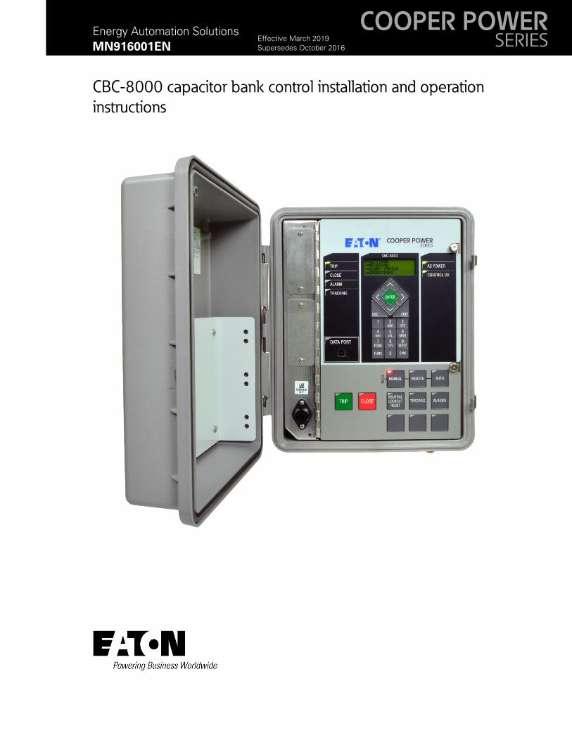
COOPER POWER SERIES MN916001EN Effective March 2019 Supersedes October 2016 Energy Automation Solutions MN916001EN CBC-8000 capacitor bank control installation and operation instructions Effective March 2019 New Information
Transcript
COOPER POWERSERIESMN916001EN
Effective March 2019Supersedes October 2016
Energy Automation Solutions
MN916001EN
CBC-8000 capacitor bank control installation and operation
instructions Effective March 2019New Information
Disclaimer of warranties and limitation of liability
The information, recommendations, descriptions and safety notations in this document are based on Eaton Corporation’s (“Eaton”) experience and judgment and may not cover all contingencies. If further information is required, an Eaton sales office should be consulted. Sale of the product shown in this literature is subject to the terms and conditions outlined in appropriate Eaton selling policies or other contractual agreement between Eaton and the purchaser.
THERE ARE NO UNDERSTANDINGS, AGREEMENTS, WARRANTIES, EXPRESSED OR IMPLIED, INCLUDING WARRANTIES OF FITNESS FOR A PARTICULAR PURPOSE OR MERCHANTABILITY, OTHER THAN THOSE SPECIFICALLY SET OUT IN ANY EXISTING CONTRACT BETWEEN THE PARTIES. ANY SUCH CONTRACT STATES THE ENTIRE OBLIGATION OF EATON. THE CONTENTS OF THIS DOCUMENT SHALL NOT BECOME PART OF OR MODIFY ANY CONTRACT BETWEEN THE PARTIES.
In no event will Eaton be responsible to the purchaser or user in contract, in tort (including negligence), strict liability or otherwise for any special, indirect, incidental or consequential damage or loss whatsoever, including but not limited to damage or loss of use of equipment, plant or power system, cost of capital, loss of power, additional expenses in the use of existing power facilities, or claims against the purchaser or user by its customers resulting from the use of the information, recommendations and descriptions contained herein. The information contained in this manual is subject to change without notice.
ii CBC-8000 capacitor bank control installation and operation instructions MN916001EN—March 2019 Eaton.com
CBC-8000 capacitor bank control installation and operation instructions MN916001EN—March 2019 Eaton.com iii
iv CBC-8000 capacitor bank control installation and operation instructions MN916001EN—March 2019 Eaton.com
Product information
Product information
Introduction
This document provides installation and operation instructions for the CBC-8000 capacitor bank control.
Refer to the following documents for additional information:
CBC-8000 capacitor bank control ProView NXG software programming guide (MN916002EN)
<Emphasis>CBC-8000 Capacitor Bank Control Communications User Guide (S1160-80-3)
Communications Point Data Base (TD916002EN)
CBC-8000 control ordering guide (CA916001EN)
CBC-8000 control reference guide (MN916004EN)
Read this manual first
Read and understand the contents of this manual and follow all locally approved procedures and safety practices before installing or operating this equipment.
Additional information
These instructions cannot cover all details or variations in the equipment, procedures, or processes described, nor provide directions for meeting every possible contingency during installation, operation, or maintenance. When additional information is needed to satisfy a problem not covered sufficiently for the user's purpose, contact your Eaton customer service representative.
Compliance standards
The CBC-8000 control is designed and tested in accordance with applicable sections of the following standards:
• IEC 61000-4-2 Electrostatic discharge
• IEC 61000-4-4 Electrical fast transient
• IEC 61000-4-5 Combination surge
• IEC 61000-4-11 Dip and interrupts
• IEC 61000-4-12 Ring/oscillatory wave
• IEC 61000-2-27 Mechanical shock
• FCC 15 Part B
The CBC-8000 control enclosure is rated NEMA 4X rain-tight when it is mounted vertically and the door latch is tightened down to compress the door’s neoprene rubber gasket.
Acceptance and initial inspection
Each CBC-8000 control is completely assembled, tested and inspected at the factory. It is carefully calibrated, adjusted and in good condition when accepted by the carrier for shipment.
Upon receipt, inspect the carton for signs of damage. Unpack the control and inspect it thoroughly for damage incurred during shipment. If damage is discovered, file a claim with the carrier immediately.
Handling and storage
Be careful during handling and storage of the CBC-8000 control to minimize the possibility of damage. If the control is to be stored for any length of time prior to installation, provide a clean, dry storage area.
Note: There are several wiring configurations available for the CBC-8000 control. Apply ac power to the control as defined by your order number. Refer to Installing the control on Page 20 in this manual.
Control specifications
The CBC-8000 control specifications are listed below.
Table 1. CBC-8000 control specifications
Spec Value
Temperature range -40° F to 185° F (-40° C to 85° C)
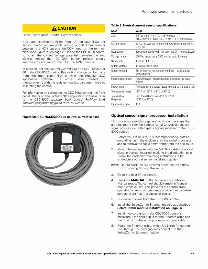
Relative humidity 5% to 95% non-condensing
Power requirements 85 to 265 Vac; 50 Hz or 60 Hz
Maximum wattage CBC-8000 control – 1 RS-232 SelectComm module: 2.5 W @ 120 Vac 3.1 W @ 240 VacCBC-8000 control – 1 Power Over Ethernet SelectComm module: 3.1 W @ 120 Vac 3.7 W @ 240 Vac
Outputs Type 1 Form C contacts interlocked and wired as two Form A outputs
Inputs Seven sensor inputs for control or monitoring; 0 - 10 Vac
Protocol DNP3 Level 2
Communications Two-Way SelectComm module: RS-232 serial port Ethernet port Wi-Fi port
Size 12.21” W x 13.93” H x 7.5” D (31 cm W x 35.38 cm H x 19.05 cm D)
Weight 9 lbs (4.08 kg) without mounting hardware
Enclosure Meets or exceeds UL 746C ultraviolet light exposure and water resistance testing
Fuse rating Eaton fuse style FNM-10 (10 A)
CBC-8000 capacitor bank control installation and operation instructions MN916001EN—March 2019 Eaton.com 1
CBC-8000 capacitor bank control description
CBC-8000 capacitor bank control description
Description
The CBC-8000 control includes extensive system control functionality, including time, temperature, current, voltage, var and sensor control operational strategies. Other standard features include, manual, automatic and remote modes, safety delay timers, control security and neutral current sensing with lockout.
The CBC-8000 control is designed for use with switched distribution feeder capacitor racks and pad mount capacitors.
The metering functions of the control include instantaneous current on a per-phase basis, instantaneous voltage and power factor on a per-phase basis, and power (real, reactive, apparent) on a per phase or total basis. The CBC-8000 control also monitors Total Harmonic Distortion (THD) and odd harmonics for voltage and current from the 3rd to the 13th harmonic.
The front panel LCD display is used to configure the operating settings for the control. It is also used to display alarms, counter information, metering, and parameters.
Parameters can also be programmed via a personal computer connected to the control through the front panel USB port. Programming, interrogation, and operations are performed with the ProView NXG application software installed on a computer.
The ProView NXG application software includes additional functions used to display configurable sequence of events, alarms, and selectable communication points.
The input voltage of the control is auto-ranging from 85 to 265 Vac and it operates on both 50 and 60 Hz systems.
Serial number and date code location
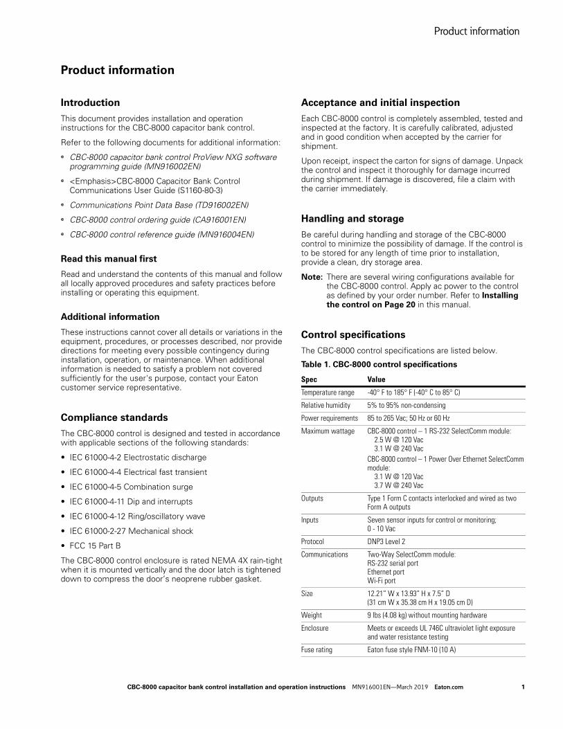
The serial number and date of manufacture for the control is printed on a label that is attached to the front panel as shown in Figure 1. Refer to this date code for any warranty questions. The date code is shown under the control serial number and it states the week and year that the control was manufactured.
Two additional labels are also provided for your use. The labels are affixed to the inside of the front cover, above the document holder.
Figure 1. CBC-8000 control serial number and date code.
Enclosure features
CBC-8000 controls manufactured after October 2016 (e.g., type 3) include the following additions:
• Door sensor
• Door latch
• Door hold
• Jaws meter base
• Ground lug
• Cable security sleeve
You can easily identify the type of control that you have by entering function code 61 on the front panel and scrolling to the Hardware ID. You can also view the control type with the ProView NXG application software by clicking Help About ProView NXG. The control types are as follows:
Type 1 – The control is a legacy control that does not con-tain the door sensor or the new board with the RTC bat-tery.
Type 2 – The control contains the new board with the RTC battery, but it does not contain the door sensor. The con-trol contains a new circuit board installed in the old legacy cabinet.
Type 3 – The control contain the new board with the Real Time Clock (RTC) battery and the new cabinet with the door sensor.
Door sensor
A door sensor provides SCADA notification and timestamps each time the control door is opened and closed. The physical door contact, wiring and circuitry are all securely contained inside the enclosure to prevent tampering.
Control Serial Number
Control Date Code
2 CBC-8000 capacitor bank control installation and operation instructions MN916001EN—March 2019 Eaton.com
CBC-8000 capacitor bank control description
Door latch
The door latches for the CBC-8000 control allow the door to be secured with 3/8 inch (1.905 cm) ring padlocks. The door latches will accommodate both the Sterling Security Systems Junior and Senior series padlocks.
Each enclosure contains two single-loop, latches that are Salt Fog Test ASTM B117 and NEMA 4X rated.
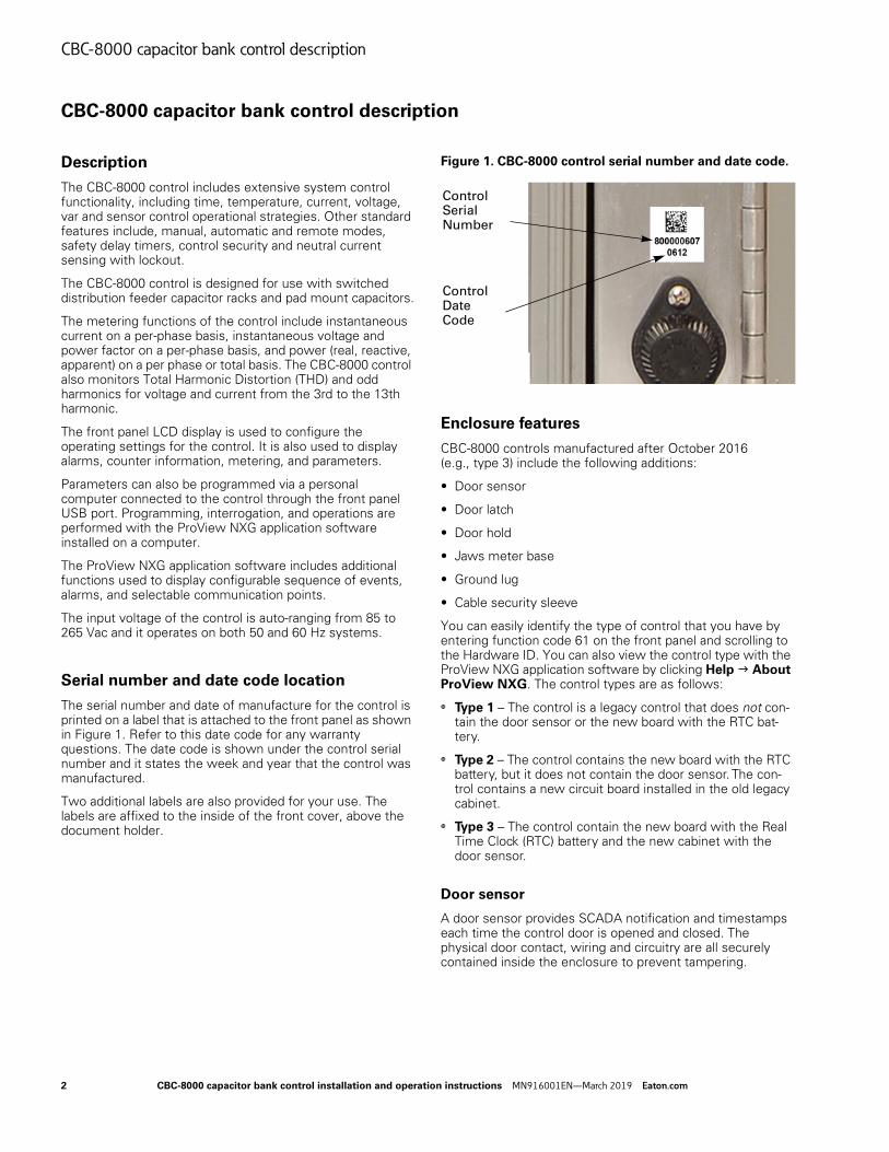
Door hold
The optional open door hold kit prevents the door swing that can occur in field maintenance situations. The open door hold will securely hold the door in a fixed, open position while an operator is accessing the HMI front panel.
The open door hold kit can be ordered for new controls or it can be installed as a field retrofit for existing controls.
The installation procedure is described in Open door hold kit installation on Page 39.
Figure 2. CBC-8000 control open door hold
Jaws meter base
The distance between the back of the enclosure and the jaws was increased to provide more room for installing and securing the meter socket ring. An additional 1/2 inch (1.27 cm) was added between the back of the pole mount enclosure and the jaws.
Ground lug
The ground lug for controls manufactured after October 2016 will accommodate a 2 AWG pole ground wire.
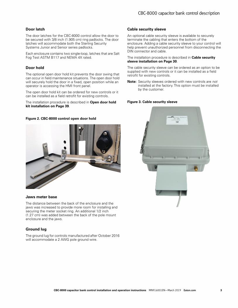
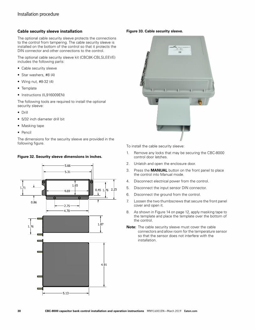
Cable security sleeve
An optional cable security sleeve is available to securely terminate the cabling that enters the bottom of the enclosure. Adding a cable security sleeve to your control will help prevent unauthorized personnel from disconnecting the DIN connector and cable.
The installation procedure is described in Cable security sleeve installation on Page 30.
The cable security sleeve can be ordered as an option to be supplied with new controls or it can be installed as a field retrofit for existing controls.
Note: Security sleeves ordered with new controls are not installed at the factory. This option must be installed by the customer.
Figure 3. Cable security sleeve
CBC-8000 capacitor bank control installation and operation instructions MN916001EN—March 2019 Eaton.com 3
CBC-8000 capacitor bank control description
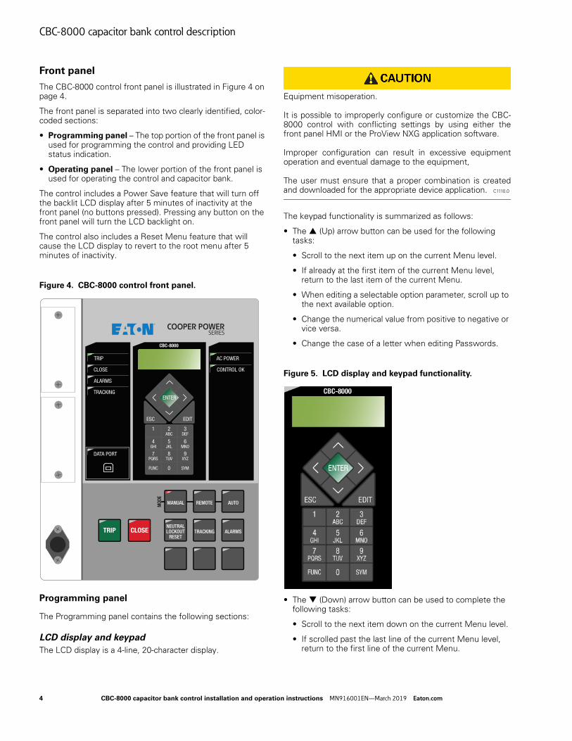
Front panel
The CBC-8000 control front panel is illustrated in Figure 4 on page 4.
The front panel is separated into two clearly identified, color-coded sections:
• Programming panel – The top portion of the front panel is used for programming the control and providing LED status indication.
• Operating panel – The lower portion of the front panel is used for operating the control and capacitor bank.
The control includes a Power Save feature that will turn off the backlit LCD display after 5 minutes of inactivity at the front panel (no buttons pressed). Pressing any button on the front panel will turn the LCD backlight on.
The control also includes a Reset Menu feature that will cause the LCD display to revert to the root menu after 5 minutes of inactivity.
Figure 4. CBC-8000 control front panel.
Programming panel
The Programming panel contains the following sections:
LCD display and keypad
The LCD display is a 4-line, 20-character display.
Equipment misoperation. It is possible to improperly configure or customize the CBC-8000 control with conflicting settings by using either the front panel HMI or the ProView NXG application software. Improper configuration can result in excessive equipment operation and eventual damage to the equipment, The user must ensure that a proper combination is created and downloaded for the appropriate device application. C1110.0
The keypad functionality is summarized as follows:
• The (Up) arrow button can be used for the following tasks:
• Scroll to the next item up on the current Menu level.
• If already at the first item of the current Menu level, return to the last item of the current Menu.
• When editing a selectable option parameter, scroll up to the next available option.
• Change the numerical value from positive to negative or vice versa.
• Change the case of a letter when editing Passwords.
Figure 5. LCD display and keypad functionality.
• The (Down) arrow button can be used to complete the following tasks:
• Scroll to the next item down on the current Menu level.
• If scrolled past the last line of the current Menu level, return to the first line of the current Menu.
CBC-8000
MANUAL REMOTE AUTO
TRACKING ALARMSNEUTRAL LOCKOUT
RESETTRIP CLOSE
MOD
E
AC POWER
CONTROL OK
TRIP
CLOSE
ALARMS
TRACKING
DATA PORT
ESC EDIT
ENTER
1 2 3
4 5 6
7 8 9
FUNC 0 SYM
PQRS XYZTUV
GHI MNOJKL
DEFABC
4 CBC-8000 capacitor bank control installation and operation instructions MN916001EN—March 2019 Eaton.com
CBC-8000 capacitor bank control description
• When editing a Selectable Option Parameter, scroll down to the next available option.
• Change the numerical value from positive to negative or vice versa.
• Change the case of a letter when editing Passwords.
• The (Left) arrow button is used to go up one Menu level.
• The (Left) arrow button is also used to move left when editing parameters.
• The (Right) arrow button is used to go down one Menu level.
• The (Right) arrow button is also used to move right when editing parameters.
• The ESC (Escape) button is used for the following tasks:
• Go up one Menu level.
• Cancel Edit mode when editing settings without changing the value.
• The ENTER button is used for the following tasks:
• Go down one Menu level.
• Confirm settings change in the Edit mode.
• Execute function codes.
• Confirm resetting the Resettable Parameters.
• Confirm passwords
• The EDIT button is used for the following tasks:
• Enter the Edit mode to make a change.
• The FUNC (Function) button is used to enter the function code mode. This mode allows you to enter a function code to go directly to a control option instead of navigating to it through the use of the front panel. For a list of the function codes, refer to the CBC-8000 Control Reference (B1160-11041) document that is shipped with the control.
• The ALPHANUMERIC buttons are used for the following tasks:
• Edit scalar parameters.
• Enter function codes.
• Enter security codes.
• Function as shortcuts to Menu items.
• The SYM (Symbol) button is used to enter special characters.
Status Indicator LEDs
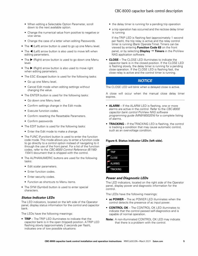
The LED indicators, located on the left side of the Operator panel, display status information for the control and capacitor bank.
The LEDs have the following meanings:
• TRIP – The TRIP LED illuminates to indicate that the capacitor bank is in the open (tripped) position. A TRIP LED flashing slowly (approximately 2 seconds per flash), indicates one of tow possible situations:
• the delay timer is running for a pending trip operation
• a trip operation has occurred and the reclose delay timer is running
If the TRIP LED is flashing fast (approximately 1 second per flash), the trip relay is active and the relay control timer is running (Bank Operate Time). Timers can be viewed by entering Function Code 63 on the front panel, or by selecting Display Timers in the ProView NXG application software.
• CLOSE – The CLOSE LED illuminates to indicate the capacitor bank is in the closed position. If the CLOSE LED is flashing slowly, the delay timer is running for a pending close operation. If the CLOSE LED is flashing fast, the close relay is active and the control timer is running.
The CLOSE LED will blink when a delayed close is active. A close will occur when the manual close delay timer expires.
• ALARM – If the ALARM LED is flashing, one or more alarms are active in the control. Refer to the CBC-8000 capacitor bank control ProView NXG software programming guide (MN916002EN) for a complete listing of alarms.
• TRACKING – If the TRACKING LED is flashing, the control is tracking a condition that may cause automatic control, such as an overvoltage condition.
Figure 6. Status indicator LEDs (left side).
Power and Diagnostic LEDs
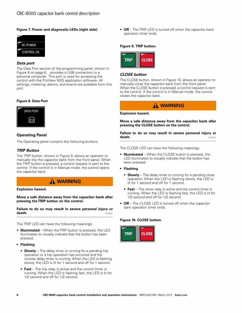
The LED indicators, located on the right side of the Operator panel, display power and diagnostic information for the control.
The LEDs have the following meanings:
• ac POWER – The ac POWER LED illuminates when the control detects the presence of ac input power.
• CONTROL OK – The CONTROL OK LED illuminates to indicate that the control passed self-diagnostics and is capable of normal operation.
Note: A non-illuminated CONTROL OK LED may indicate that there is a problem with the control.
CBC-8000 capacitor bank control installation and operation instructions MN916001EN—March 2019 Eaton.com 5
CBC-8000 capacitor bank control description
Figure 7. Power and diagnostic LEDs (right side).
Data port
The Data Port section of the programming panel, shown in Figure 8 on page 6, provides a USB connection to a personal computer. This port is used for accessing the control with the ProView NXG application software. All settings, metering, alarms, and events are available from this port.
Figure 8. Data Port
Operating Panel
The Operating panel contains the following buttons:
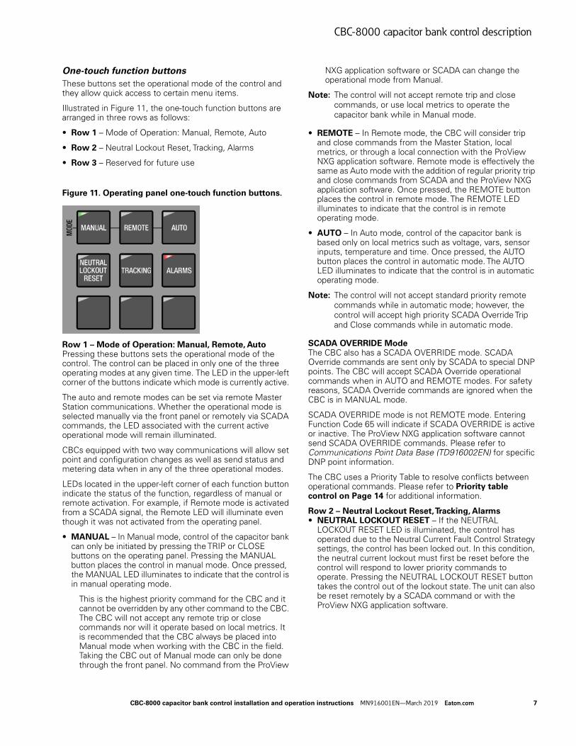
TRIP Button
The TRIP button, shown in Figure 9, allows an operator to manually trip the capacitor bank from the front panel. When the TRIP button is pressed, a control request is sent to the control. If the control is in Manual mode, the control opens the capacitor bank.
Explosion hazard. Move a safe distance away from the capacitor bank after pressing the TRIP button on the control. Failure to do so may result in severe personal injury or death. C1103.0
The TRIP LED can have the following meanings:
• Illuminated – When the TRIP button is pressed, the LED illuminates to visually indicate that the button has been pressed.
• Flashing
• Slowly – The delay timer is running for a pending trip operation or a trip operation has occurred and the reclose delay timer is running. When the LED is flashing slowly, the LED is lit for 1 second and off for 1 second.
• Fast – The trip relay is active and the control timer is running. When the LED is flashing fast, the LED is lit for 1/2 second and off for 1/2 second.
• Off – The TRIP LED is turned off when the capacitor bank operation timer ends.
Figure 9. TRIP button.
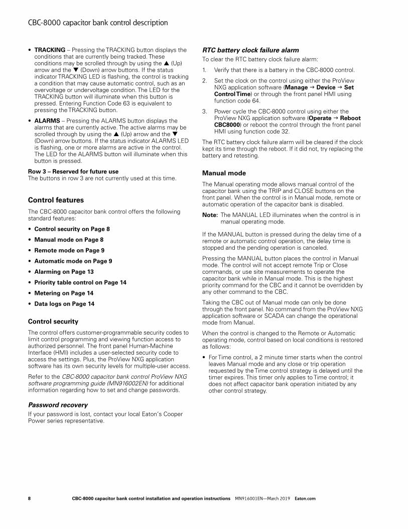
CLOSE button
The CLOSE button, shown in Figure 10, allows an operator to manually close the capacitor bank from the front panel. When the CLOSE button is pressed, a control request is sent to the control. If the control is in Manual mode, the control closes the capacitor bank.
Explosion hazard. Move a safe distance away from the capacitor bank after pressing the CLOSE button on the control. Failure to do so may result in severe personal injury or death. C1104.0
The CLOSE LED can have the following meanings:
• Illuminated – When the CLOSE button is pressed, the LED illuminates to visually indicate that the button has been pressed.
• Flashing
• Slowly – The delay timer is running for a pending close operation. When the LED is flashing slowly, the LED is lit for 1 second and off for 1 second.
• Fast – The close relay is active and the control timer is running. When the LED is flashing fast, the LED is lit for 1/2 second and off for 1/2 second.
• Off – The CLOSE LED is turned off when the capacitor bank operation timer ends.
Figure 10. CLOSE button.
6 CBC-8000 capacitor bank control installation and operation instructions MN916001EN—March 2019 Eaton.com
CBC-8000 capacitor bank control description
One-touch function buttons
These buttons set the operational mode of the control and they allow quick access to certain menu items.
Illustrated in Figure 11, the one-touch function buttons are arranged in three rows as follows:
• Row 1 – Mode of Operation: Manual, Remote, Auto
• Row 2 – Neutral Lockout Reset, Tracking, Alarms
• Row 3 – Reserved for future use
Figure 11. Operating panel one-touch function buttons.
Row 1 – Mode of Operation: Manual, Remote, AutoPressing these buttons sets the operational mode of the control. The control can be placed in only one of the three operating modes at any given time. The LED in the upper-left corner of the buttons indicate which mode is currently active.
The auto and remote modes can be set via remote Master Station communications. Whether the operational mode is selected manually via the front panel or remotely via SCADA commands, the LED associated with the current active operational mode will remain illuminated.
CBCs equipped with two way communications will allow set point and configuration changes as well as send status and metering data when in any of the three operational modes.
LEDs located in the upper-left corner of each function button indicate the status of the function, regardless of manual or remote activation. For example, if Remote mode is activated from a SCADA signal, the Remote LED will illuminate even though it was not activated from the operating panel.
• MANUAL – In Manual mode, control of the capacitor bank can only be initiated by pressing the TRIP or CLOSE buttons on the operating panel. Pressing the MANUAL button places the control in manual mode. Once pressed, the MANUAL LED illuminates to indicate that the control is in manual operating mode.
This is the highest priority command for the CBC and it cannot be overridden by any other command to the CBC. The CBC will not accept any remote trip or close commands nor will it operate based on local metrics. It is recommended that the CBC always be placed into Manual mode when working with the CBC in the field. Taking the CBC out of Manual mode can only be done through the front panel. No command from the ProView
NXG application software or SCADA can change the operational mode from Manual.
Note: The control will not accept remote trip and close commands, or use local metrics to operate the capacitor bank while in Manual mode.
• REMOTE – In Remote mode, the CBC will consider trip and close commands from the Master Station, local metrics, or through a local connection with the ProView NXG application software. Remote mode is effectively the same as Auto mode with the addition of regular priority trip and close commands from SCADA and the ProView NXG application software. Once pressed, the REMOTE button places the control in remote mode. The REMOTE LED illuminates to indicate that the control is in remote operating mode.
• AUTO – In Auto mode, control of the capacitor bank is based only on local metrics such as voltage, vars, sensor inputs, temperature and time. Once pressed, the AUTO button places the control in automatic mode. The AUTO LED illuminates to indicate that the control is in automatic operating mode.
Note: The control will not accept standard priority remote commands while in automatic mode; however, the control will accept high priority SCADA Override Trip and Close commands while in automatic mode.
SCADA OVERRIDE ModeThe CBC also has a SCADA OVERRIDE mode. SCADA Override commands are sent only by SCADA to special DNP points. The CBC will accept SCADA Override operational commands when in AUTO and REMOTE modes. For safety reasons, SCADA Override commands are ignored when the CBC is in MANUAL mode.
SCADA OVERRIDE mode is not REMOTE mode. Entering Function Code 65 will indicate if SCADA OVERRIDE is active or inactive. The ProView NXG application software cannot send SCADA OVERRIDE commands. Please refer to Communications Point Data Base (TD916002EN) for specific DNP point information.
The CBC uses a Priority Table to resolve conflicts between operational commands. Please refer to Priority table control on Page 14 for additional information.
Row 2 – Neutral Lockout Reset, Tracking, Alarms• NEUTRAL LOCKOUT RESET – If the NEUTRAL
LOCKOUT RESET LED is illuminated, the control has operated due to the Neutral Current Fault Control Strategy settings, the control has been locked out. In this condition, the neutral current lockout must first be reset before the control will respond to lower priority commands to operate. Pressing the NEUTRAL LOCKOUT RESET button takes the control out of the lockout state. The unit can also be reset remotely by a SCADA command or with the ProView NXG application software.
CBC-8000 capacitor bank control installation and operation instructions MN916001EN—March 2019 Eaton.com 7
CBC-8000 capacitor bank control description
• TRACKING – Pressing the TRACKING button displays the conditions that are currently being tracked. These conditions may be scrolled through by using the (Up) arrow and the (Down) arrow buttons. If the status indicator TRACKING LED is flashing, the control is tracking a condition that may cause automatic control, such as an overvoltage or undervoltage condition. The LED for the TRACKING button will illuminate when this button is pressed. Entering Function Code 63 is equivalent to pressing the TRACKING button.
• ALARMS – Pressing the ALARMS button displays the alarms that are currently active. The active alarms may be scrolled through by using the (Up) arrow and the (Down) arrow buttons. If the status indicator ALARMS LED is flashing, one or more alarms are active in the control. The LED for the ALARMS button will illuminate when this button is pressed.
Row 3 – Reserved for future useThe buttons in row 3 are not currently used at this time.
Control features
The CBC-8000 capacitor bank control offers the following standard features:
• Control security on Page 8
• Manual mode on Page 8
• Remote mode on Page 9
• Automatic mode on Page 9
• Alarming on Page 13
• Priority table control on Page 14
• Metering on Page 14
• Data logs on Page 14
Control security
The control offers customer-programmable security codes to limit control programming and viewing function access to authorized personnel. The front panel Human-Machine Interface (HMI) includes a user-selected security code to access the settings. Plus, the ProView NXG application software has its own security levels for multiple-user access.
Refer to the CBC-8000 capacitor bank control ProView NXG software programming guide (MN916002EN) for additional information regarding how to set and change passwords.
Password recovery
If your password is lost, contact your local Eaton’s Cooper Power series representative.
RTC battery clock failure alarm
To clear the RTC battery clock failure alarm:
1. Verify that there is a battery in the CBC-8000 control.
2. Set the clock on the control using either the ProView NXG application software (Manage Device Set Control Time) or through the front panel HMI using function code 64.
3. Power cycle the CBC-8000 control using either the ProView NXG application software (Operate Reboot CBC8000) or reboot the control through the front panel HMI using function code 32.
The RTC battery clock failure alarm will be cleared if the clock kept its time through the reboot. If it did not, try replacing the battery and retesting.
Manual mode
The Manual operating mode allows manual control of the capacitor bank using the TRIP and CLOSE buttons on the front panel. When the control is in Manual mode, remote or automatic operation of the capacitor bank is disabled.
Note: The MANUAL LED illuminates when the control is in manual operating mode.
If the MANUAL button is pressed during the delay time of a remote or automatic control operation, the delay time is stopped and the pending operation is canceled.
Pressing the MANUAL button places the control in Manual mode. The control will not accept remote Trip or Close commands, or use site measurements to operate the capacitor bank while in Manual mode. This is the highest priority command for the CBC and it cannot be overridden by any other command to the CBC.
Taking the CBC out of Manual mode can only be done through the front panel. No command from the ProView NXG application software or SCADA can change the operational mode from Manual.
When the control is changed to the Remote or Automatic operating mode, control based on local conditions is restored as follows:
• For Time control, a 2 minute timer starts when the control leaves Manual mode and any close or trip operation requested by the Time control strategy is delayed until the timer expires. This timer only applies to Time control; it does not affect capacitor bank operation initiated by any other control strategy.
8 CBC-8000 capacitor bank control installation and operation instructions MN916001EN—March 2019 Eaton.com
CBC-8000 capacitor bank control description
• For all other Auto control requests, a 30 second manual delay timer is started when the control is removed from Manual mode. This is done as a safety measure to prevent immediate capacitor bank operation in case a track timer is set to a short time period. If a local condition starts tracking, before the 30 second manual delay timer has finished, the remaining amount of time for the manual delay timer is added to the tracking timer for the local condition that is requesting the operation. This ensures that the manual delay timer is allowed to run for the entire 30 second time period and that the track timer is allowed to run for its entire duration.
Manual close delay time
The manual close delay timer provides a delay from the time that the manual CLOSE button is pressed to the time that the manual close operation is performed. This delay gives service personnel time to move away from the capacitor bank before the switch actually closes. The CLOSE LED blinks when the manual close delay timer is active.
The manual close delay is programmable from 30 to 255 seconds in 1 second increments.
Remote mode
The Remote operating mode allows remote operation of the capacitor bank using a serial or Ethernet SelectComm communication module or a local USB connection with the ProView NXG application software. Manual operation of the capacitor bank is disabled when the control is in Remote mode. However, automatic control is allowed when the control is in the remote operating mode.
When the control is in Remote mode, commands are accepted from the Master Station
Note: The REMOTE LED illuminates when the control is in remote operating mode.
If the control is in Manual or Automatic mode and the REMOTE button is pressed, any trip or close operation that was initiated when the control was in Manual or Automatic mode is performed before the control changes to the Remote operating mode.
Remote SCADA override
Remote SCADA override is a special remote control request, to trip or close the capacitor bank. It has a control table priority that is higher than all of the other control table priorities, except for Manual control.
Automatic mode
The Automatic operating mode allows control of the capacitor bank, based on local conditions, while preventing manual or remote control of the capacitor bank except when the Remote SCADA Override trip or close command is used.
Note: The AUTO LED illuminates when the control is in automatic operating mode.
If the control is in Manual or Remote mode and the AUTO button is pressed, any trip or close operation that was initiated when the control was in Manual or Remote mode is performed before the control changes to Automatic operating mode.
The following automatic control operations are supported:
• Seasonal control – Seasonal control allows the control to use a different set of control parameters for two separate control seasons.
• Over Voltage Under Voltage control – Capacitor bank control is based on the line voltage measurement and whether or not it is outside of a configurable Over Voltage Under Voltage (OVUV) threshold for a configurable period of time.
• Emergency voltage control – Capacitor bank control is based on the line voltage measurement and whether or not it is outside of a configurable Emergency OVUV threshold for a configurable period of time.
• var control – Capacitor bank control is based on the fundamental kvar measurement and whether or not it is outside of a configurable threshold for a configurable period of time.
• Time control – Capacitor bank control is based on the time of day.
• Temperature control – Capacitor bank control is based on the temperature measurement and whether or not it outside of a configurable threshold for a configurable period of time.
• Sensor Input control – Capacitor bank control is based on the sensor input value and whether or not it is outside of a configurable threshold for a configurable period of time.
• Current control – Capacitor bank control is based on the sensor input current value and whether or not it is outside of the current threshold for a configurable period of time.
• Neutral current fault control – Monitors the health of the capacitor bank by using the fundamental neutral current measurement to determine if there is a phase imbalance. A phase imbalance is common when a capacitor’s fuse is blown or when a capacitor switch has failed. If a fault condition is detected, the control will not perform any control operation.
• Neutral current verification – Capacitor bank operation is verified by comparing the fundamental neutral current measurement to a configurable set point.
• Communications loss control – If the control does not hear from the master station for a configurable period of time, the control will allow operations to occur based on local metrics.
• Adaptive voltage control – Capacitor bank control is based on a predictive algorithm that determines whether or not a capacitor bank operation will cause an OVUV condition or emergency voltage condition.
If the resulting control action will place the voltage outside of the OV, UV, or emergency voltage thresholds,
CBC-8000 capacitor bank control installation and operation instructions MN916001EN—March 2019 Eaton.com 9
CBC-8000 capacitor bank control description
then the CBC-8000 control will reject the control command.
Seasonal control
The seasonal control feature is used to configure two separate seasonal time periods for the following control methods:
• Voltage control
• var control
• Time control
• Temperature control
When seasonal control is enabled, each control method within season 1 or season 2 can have a unique set of control parameters.
Over Voltage Under Voltage control
The Over Voltage Under Voltage (OVUV) control feature allows control of the capacitor bank if the line voltage measured by the control is outside of the configurable OVUV thresholds for a configurable period of time.
• The control supports the following OVUV thresholds:
• Non-seasonal OVUV thresholds – Used when the control performs non-seasonal control.
• Seasonal OVUV thresholds – Used when the control performs seasonal control.
• Comms Loss OVUV thresholds – Used when the control loses communications with the master station.
• CVR thresholds – Used when the control performs CVR (Conservation Voltage Reduction) control.
• The configurable periods of time that the line voltage must be outside of a threshold are the OV track time and UV track time, which are in seconds.
If adaptive voltage sensing is also enabled, other automatic control conditions will only be considered if a control operation will not cause an OVUV condition.
Emergency voltage control
The emergency voltage control feature allows control of the capacitor bank if the line voltage measured by the control is outside of the emergency voltage thresholds for a configurable period of time.
If adaptive voltage sensing is also enabled, other automatic control conditions will only be considered if a control operation will not cause an emergency OVUV condition.
var control
The var control feature allows control of the capacitor bank if the fundamental kvar measurement is outside of a configurable threshold for a configurable period of time.
• The configurable thresholds are the trip and close points, which are in kvar.
• The configurable period of time that the kvar value must be outside of a threshold is the var track time, which is in seconds.
The control stops tracking kvar measurements if the capacitor bank is already tripped and the kvar value is below the trip point or the capacitor bank is already closed and the kvar value is above the close point.
Time control
The time control feature allows daily control of the capacitor bank when the local time reaches the On time or Off time.
• On time – When the local time reaches the On time, the control closes the capacitor bank and it remains closed until the local time reaches the Off time.
• Off time – When the local time reaches the Off time, the control opens the capacitor bank and it remains open until the local time reaches the On time.
Time control can be used during the week (Monday through Friday) and on the weekend. In addition, the control supports the following time control options:
• Holidays – User-defined holidays and perpetual holidays, which are holidays that do not occur on a specific date, such as Thanksgiving, Memorial Day, and Labor Day.
• ON/OFF control – On/Off control with a selectable Off state. During the On time period, the control will only operate local controls. During the Off time period, the control will remain in one of three configurable states: Trip, Close, or the last known state. Also, during the Off time period, only manual, SCADA, fault, and emergency controls will be allowed.
• Weekend ON/OFF control – Weekend On/Off control only applies to Saturday and Sunday. When the local time reaches the weekend On time, the control closes the capacitor bank and it remains closed until the local time reaches the Off time. When the local time reaches the weekend Off time, the control opens the capacitor bank it remains open until the local time reaches the On time.
Temperature control
The temperature control feature allows control of the capacitor bank if the temperature is outside of the temperature thresholds for a configurable period of time.
The control action that occurs is configurable:
• None – Do not perform an operation.
• Trip above – Perform a trip operation when the temperature is above the threshold.
• Close above – Perform a close operation when the temperature is above the threshold.
• Trip above close below – Perform a trip operation when the temperature is above the threshold and perform a close operation when the temperature is below the threshold.
• Trip below – Perform a trip operation when the temperature is below the threshold.
10 CBC-8000 capacitor bank control installation and operation instructions MN916001EN—March 2019 Eaton.com
CBC-8000 capacitor bank control description
• Close below – Perform a close operation when the temperature is below the threshold.
• Close above trip below – Perform a close operation when the temperature is above the threshold and perform a trip operation when the temperature is below the threshold.
Note: Make sure the actions that are specified for the minimum and maximum thresholds do not cause conflicting control operations. For example, the minimum action cannot be trip above if the maximum action is close below.
Sensor input control
The sensor input control feature allows control of the capacitor bank if the sensor input value stays outside of a configurable threshold for a configurable period of time.
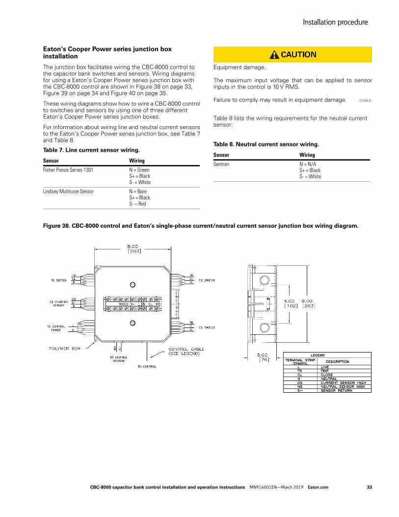
Equipment damage. The maximum input voltage that can be applied to sensor inputs in the control is 10 V RMS. Failure to comply may result in equipment damage. C1105.0
The control action that occurs is configurable:
• None – Do not perform an operation.
• Trip above – Perform a trip operation when the sensor input value is above the threshold.
• Close above – Perform a close operation when the sensor input value is above the threshold.
• Trip above close below – Perform a trip operation when the sensor input value is above the threshold and perform a close operation when the sensor input value is below the threshold.
• Trip below – Perform a trip operation when the sensor input value is below the threshold.
• Close below – Perform a close operation when the sensor input value is below the threshold.
• Close above trip below – Perform a close operation when the sensor input value is above the threshold and perform a trip operation when the sensor input value is below the threshold.
Note: Make sure the actions that are specified for the minimum and maximum thresholds do not cause conflicting control operations. For example, the minimum action cannot be trip above if the maximum action is close below.
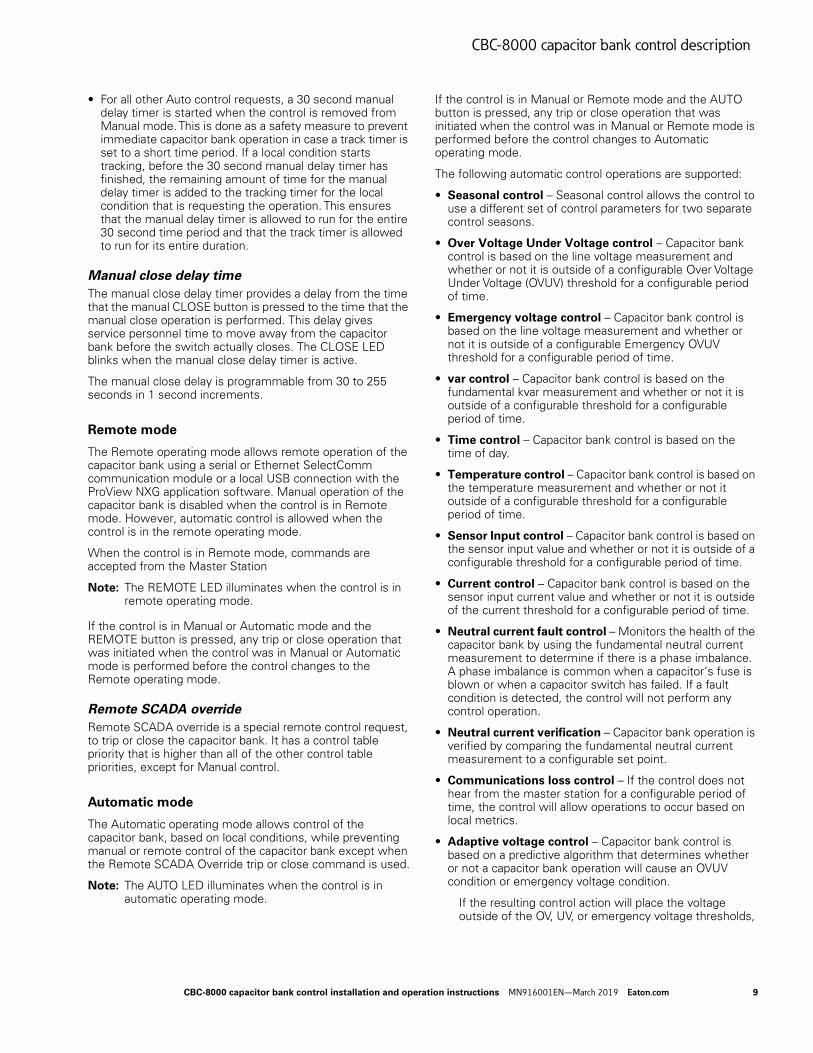
Current control – use case for sensor input control
Current control can be accomplished using the sensor input controls if the site is equipped with current monitoring sensors. Figure 12 is a picture of combination voltage and current sensors installed on all three phases.
As an example, a customer would like to have the capacitor bank close in above 200 A and open up below 100 A. The minimum threshold action would be trip below with a value of 100 and the maximum threshold action would be close above with a value of 200.
If it is desirable that the capacitor bank remain closed in between 100 A and 200 A, the minimum threshold action would be set to close above trip below and the maximum threshold action would remain at close above.
Figure 12. Capacitor banks with 3-phase line voltage/current sensors.
Neutral current fault control
Neutral current fault control provides a method to determine if the capacitor bank is in a fault condition, such as a phase imbalance. If neutral fault current control is enabled and the measured fundamental neutral current exceeds the configurable set point for a configurable period of time, the following occurs:
• The control places the capacitor bank into the opposite state from the one that caused the fault current.
• All control operations, except for manual control and SCADA override control, are prohibited.
• The keypad can still be used to view control settings and data during a fault condition.
• The measured fundamental neutral current, at the time of the fault, is stored in non-volatile memory. The neutral current value that caused the fault can then be retrieved at a later time.
• The LED on the NEUTRAL LOCKOUT RESET button will be illuminated.
3-Phase Line Voltage/Current Sensors
Capacitor Banks
CBC-8000 capacitor bank control installation and operation instructions MN916001EN—March 2019 Eaton.com 11
CBC-8000 capacitor bank control description
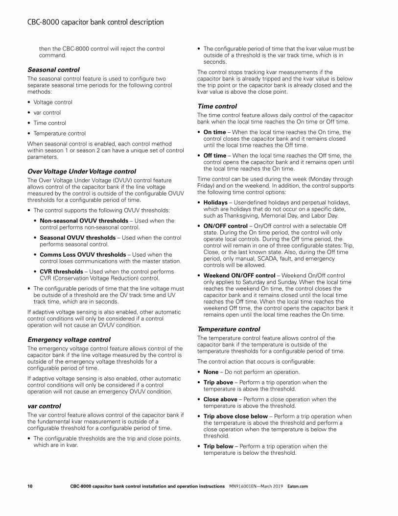
Note: A neutral current sensor must be connected to the control prior to enabling neutral current fault control.
The neutral current lockout can be cleared by pressing the Neutral Lockout Reset button on the operating panel or by sending a neutral lockout reset command to the control over local/remote comms. When the neutral current lockout is cleared, the fault current value in non-volatile memory is also cleared and the LED on the NEUTRAL LOCKOUT RESET button will no longer be illuminated.
Figure 13. Neutral current sensor.
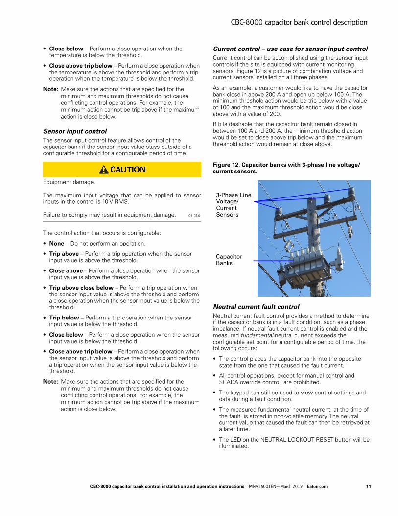
Figure 14. Neutral current sensor 120 Vac system.
Neutral current verification
The neutral current verification feature provides a method to verify capacitor bank operation by comparing the RMS neutral current measurement to a configurable set point.
Note: Neutral current sensing must be enabled to use neutral current readings to verify capacitor bank operation. To use neutral current sensing, a neutral current sensor must be connected to the control prior to enabling this feature.
The neutral current measurement is expected to be above the configurable set point for a closed capacitor bank and below this set point for a tripped capacitor bank.
• If the neutral current measurement is not above the set point for a closed capacitor bank, the control attempts to close the capacitor bank a configurable number of times before the operation is considered a failure.
• If the neutral current measurement is not below the set point for an open capacitor bank, the control attempts to open the capacitor bank a configurable number of times before the operation is considered a failure.
Note: If neutral current fault control is enabled and the control is in a fault current condition, the control will not perform any capacitor bank operation.
Neutral current fault control versus neutral current verification
Neutral Current Fault Control and Neutral Current Verification are separate features for monitoring the health of the capacitor bank and associated equipment. Both features require a neutral current sensor, although each operates on a different neutral current measurement according to its requirements.
Neutral current fault controlNeutral current fault control is the most commonly used feature. It detects when the capacitors on different phases become imbalanced due to failed equipment (e.g., a blown fuse or a stuck switch).
A typical setting for the Fault Control Setpoint is 75% of the current that flows through one phase. When the filtered 60 Hz neutral current is higher than the specified setpoint, the control will operate the working phases into the opposite state to balance the capacitor bank's effect on the line, then the control will lock in that state and set an alarm indicating that a neutral current lockout has occurred. Note that neutral current fault control uses the filtered 60 Hz neutral current to avoid false positives due to harmonic currents which can often be high through a capacitor bank, but do not indicate equipment failure.
Neutral current verification Neutral current verification operates on the principal that when the capacitor bank is closed a small amount of neutral current is expected to be present. Neutral current verification is intended to provide feedback on whether a capacitor bank operation appeared successful based on the amount of neutral current.
12 CBC-8000 capacitor bank control installation and operation instructions MN916001EN—March 2019 Eaton.com
CBC-8000 capacitor bank control description
When the specified current is not seen on a close operation, or if the unfiltered RMS neutral current does not go to 0 amps on a trip operation, the operation is retried a specified number of times. If the operation does not appear to be successful, an alarm point will be set.
Note that if the line is very balanced, the neutral current verification feature may not see the current it expects and therefore may give a false positive. Due to the nature of the distribution system dynamics, careful planning and review of the data is necessary to reduce the number of false positives and make this feature effective. Note that this feature uses the unfiltered RMS neutral current, which allows the harmonic current to help determine that the capacitor bank was successfully closed, which in turn reduces the number of false positives reported by this feature.
Communications loss control
If the control cannot communicate with the master station for a configurable period of time, the control enters comms loss mode.
The following automatic control types may be enabled when the control enters comms loss mode:
• OVUV control
• var control
• Time control
• Temperature control
• Sensor Input control
• Current control
Note: OVUV control uses a secondary set of thresholds when the control is in comms loss mode.
Note: If a stand-alone control contains a SelectComm communications module, you must set the port type to unused; otherwise, the control will go into Communications Loss operating mode and activate that alarm. Refer to the <Emphasis>CBC-8000 Capacitor Bank Control Communications User Guide (S1160-80-3) for this procedure.
Adaptive voltage sensing
Adaptive voltage sensing is a predictive algorithm that is used to determine if a control operation will cause an OVUV or emergency OVUV voltage condition. The average delta voltage, which measures the change in voltage due to a capacitor bank operation, is used along with a 10 second average of the instantaneous line voltage to see if a control operation will cause the voltage to be outside of the OVUV thresholds or emergency voltage thresholds.
If the pending control operation will cause an OVUV or emergency OVUV voltage condition and it has a priority lower than OVUV or emergency voltage control, the control operation is ignored. Any control operation that has a higher priority than OVUV or emergency OVUV voltage control is allowed.
Adaptive voltage sensing is used only if OVUV control or emergency voltage control is enabled.
Note: The average delta voltage is only updated when the control believes its operation changed the capacitor bank to the opposite state.
For example, if the capacitor bank is closed and you execute a close command, or if the capacitor bank is open and you execute a trip command, the control will not update the average delta voltage reading since the control did not change the state of the capacitor bank.
Alarming
Alarming allows the control to set alerts under specific conditions. The alarming feature is used to indicate when an event or condition has occurred. The control supports three types of alarms:
• Data – Sets an alarm if a metering value stays outside a threshold for a configurable period of time. High and low thresholds may be set for each metering value. Data alarming is available for the following conditions:
• Line voltage: high, low and THD.
• 3-phase: kvar high and low, kW high and low.
• var power factor: leading and lagging.
• Temperature: high and low.
• Sensor inputs 1 through 6: high and low.
• Neutral current: total, fundamental, and THD.
• Phases A through C: voltage total high and low, voltage THD, current total, current THD, leading power factor, lagging power factor, kW high and low, kvar high and low.
• Status – Sets an alarm if a status value stays active for a configurable period of time. Status alarms include:
• Phases A through C: power flow
• var power flow
• Event – Sets an alarm if a specific event occurs. Event alarms that can be viewed on the front panel display include:
• Abnormal delta voltage
• ac power present
• Bad active relay: close or trip
• Control request
• Controller mode
• Ignored control reason
• Maximum operations count
• Neutral current lockout
• Operation failed
• Override mode: CVR or SCADA
• Power fail
• Relay stuck: closed or tripped
CBC-8000 capacitor bank control installation and operation instructions MN916001EN—March 2019 Eaton.com 13
CBC-8000 capacitor bank control description
• Relay sense failed
• Track timer: sensor input 1-6, emergency, fault current, OVUV or var
Information about an alarm can be stored in the Sequence of Event (SOE) log.
Note: Alarms are not enabled by default and they must be configured by using the front panel or with the ProView NXG application software.
Priority table control
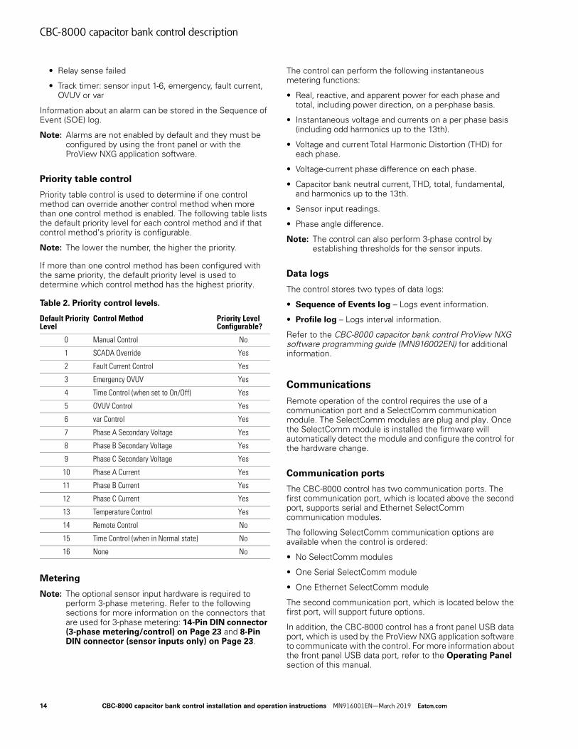
Priority table control is used to determine if one control method can override another control method when more than one control method is enabled. The following table lists the default priority level for each control method and if that control method’s priority is configurable.
Note: The lower the number, the higher the priority.
If more than one control method has been configured with the same priority, the default priority level is used to determine which control method has the highest priority.
Metering
Note: The optional sensor input hardware is required to perform 3-phase metering. Refer to the following sections for more information on the connectors that are used for 3-phase metering: 14-Pin DIN connector (3-phase metering/control) on Page 23 and 8-Pin DIN connector (sensor inputs only) on Page 23.
The control can perform the following instantaneous metering functions:
• Real, reactive, and apparent power for each phase and total, including power direction, on a per-phase basis.
• Instantaneous voltage and currents on a per phase basis (including odd harmonics up to the 13th).
• Voltage and current Total Harmonic Distortion (THD) for each phase.
• Voltage-current phase difference on each phase.
• Capacitor bank neutral current, THD, total, fundamental, and harmonics up to the 13th.
• Sensor input readings.
• Phase angle difference.
Note: The control can also perform 3-phase control by establishing thresholds for the sensor inputs.
Data logs
The control stores two types of data logs:
• Sequence of Events log – Logs event information.
• Profile log – Logs interval information.
Refer to the CBC-8000 capacitor bank control ProView NXG software programming guide (MN916002EN) for additional information.
Communications
Remote operation of the control requires the use of a communication port and a SelectComm communication module. The SelectComm modules are plug and play. Once the SelectComm module is installed the firmware will automatically detect the module and configure the control for the hardware change.
Communication ports
The CBC-8000 control has two communication ports. The first communication port, which is located above the second port, supports serial and Ethernet SelectComm communication modules.
The following SelectComm communication options are available when the control is ordered:
• No SelectComm modules
• One Serial SelectComm module
• One Ethernet SelectComm module
The second communication port, which is located below the first port, will support future options.
In addition, the CBC-8000 control has a front panel USB data port, which is used by the ProView NXG application software to communicate with the control. For more information about the front panel USB data port, refer to the Operating Panel section of this manual.
Table 2. Priority control levels.
Default Priority Level
Control Method Priority Level Configurable?
0 Manual Control No
1 SCADA Override Yes
2 Fault Current Control Yes
3 Emergency OVUV Yes
4 Time Control (when set to On/Off) Yes
5 OVUV Control Yes
6 var Control Yes
7 Phase A Secondary Voltage Yes
8 Phase B Secondary Voltage Yes
9 Phase C Secondary Voltage Yes
10 Phase A Current Yes
11 Phase B Current Yes
12 Phase C Current Yes
13 Temperature Control Yes
14 Remote Control No
15 Time Control (when in Normal state) No
16 None No
14 CBC-8000 capacitor bank control installation and operation instructions MN916001EN—March 2019 Eaton.com
CBC-8000 capacitor bank control description
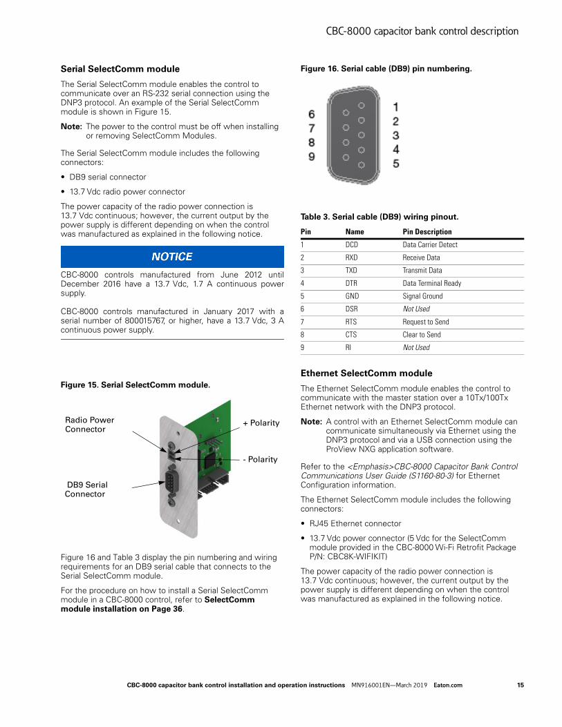
Serial SelectComm module
The Serial SelectComm module enables the control to communicate over an RS-232 serial connection using the DNP3 protocol. An example of the Serial SelectComm module is shown in Figure 15.
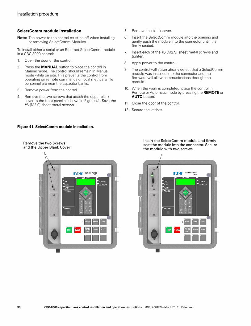
Note: The power to the control must be off when installing or removing SelectComm Modules.
The Serial SelectComm module includes the following connectors:
• DB9 serial connector
• 13.7 Vdc radio power connector
The power capacity of the radio power connection is 13.7 Vdc continuous; however, the current output by the power supply is different depending on when the control was manufactured as explained in the following notice.
CBC-8000 controls manufactured from June 2012 until December 2016 have a 13.7 Vdc, 1.7 A continuous power supply. CBC-8000 controls manufactured in January 2017 with a serial number of 800015767, or higher, have a 13.7 Vdc, 3 A continuous power supply.
Figure 15. Serial SelectComm module.
Figure 16 and Table 3 display the pin numbering and wiring requirements for an DB9 serial cable that connects to the Serial SelectComm module.
For the procedure on how to install a Serial SelectComm module in a CBC-8000 control, refer to SelectComm module installation on Page 36.
Figure 16. Serial cable (DB9) pin numbering.
Ethernet SelectComm module
The Ethernet SelectComm module enables the control to communicate with the master station over a 10Tx/100Tx Ethernet network with the DNP3 protocol.
Note: A control with an Ethernet SelectComm module can communicate simultaneously via Ethernet using the DNP3 protocol and via a USB connection using the ProView NXG application software.
Refer to the <Emphasis>CBC-8000 Capacitor Bank Control Communications User Guide (S1160-80-3) for Ethernet Configuration information.
The Ethernet SelectComm module includes the following connectors:
• RJ45 Ethernet connector
• 13.7 Vdc power connector (5 Vdc for the SelectComm module provided in the CBC-8000 Wi-Fi Retrofit Package P/N: CBC8K-WIFIKIT)
The power capacity of the radio power connection is 13.7 Vdc continuous; however, the current output by the power supply is different depending on when the control was manufactured as explained in the following notice.
Radio Power Connector
DB9 Serial Connector
+ Polarity
- Polarity
Table 3. Serial cable (DB9) wiring pinout.
Pin Name Pin Description
1 DCD Data Carrier Detect
2 RXD Receive Data
3 TXD Transmit Data
4 DTR Data Terminal Ready
5 GND Signal Ground
6 DSR Not Used
7 RTS Request to Send
8 CTS Clear to Send
9 RI Not Used
CBC-8000 capacitor bank control installation and operation instructions MN916001EN—March 2019 Eaton.com 15
CBC-8000 capacitor bank control description
CBC-8000 controls manufactured from June 2012 until December 2016 have a 13.7 Vdc, 1.7 A continuous power supply. CBC-8000 controls manufactured in January 2017 with a serial number of 800015767, or higher, have a 13.7 Vdc, 3 A continuous power supply.
For the procedure to install the Ethernet SelectComm module in a CBC-8000 control, refer to SelectComm module installation on Page 36.
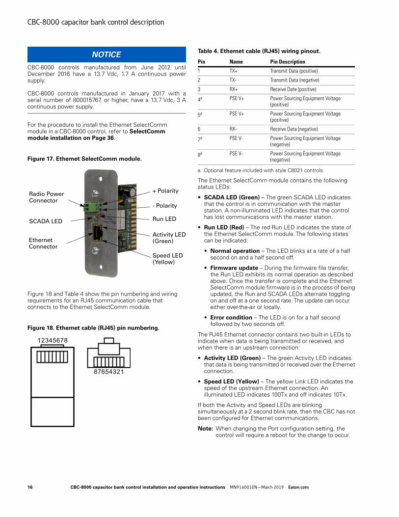
Figure 17. Ethernet SelectComm module.
Figure 18 and Table 4 show the pin numbering and wiring requirements for an RJ45 communication cable that connects to the Ethernet SelectComm module.
Figure 18. Ethernet cable (RJ45) pin numbering.
The Ethernet SelectComm module contains the following status LEDs:
• SCADA LED (Green) – The green SCADA LED indicates that the control is in communication with the master station. A non-illuminated LED indicates that the control has lost communications with the master station.
• Run LED (Red) – The red Run LED indicates the state of the Ethernet SelectComm module. The following states can be indicated:
• Normal operation – The LED blinks at a rate of a half second on and a half second off.
• Firmware update – During the firmware file transfer, the Run LED exhibits its normal operation as described above. Once the transfer is complete and the Ethernet SelectComm module firmware is in the process of being updated, the Run and SCADA LEDs alternate toggling on and off at a one second rate. The update can occur either over-the-air or locally.
• Error condition – The LED is on for a half second followed by two seconds off.
The RJ45 Ethernet connector contains two built-in LEDs to indicate when data is being transmitted or received, and when there is an upstream connection:
• Activity LED (Green) – The green Activity LED indicates that data is being transmitted or received over the Ethernet connection.
• Speed LED (Yellow) – The yellow Link LED indicates the speed of the upstream Ethernet connection. An illuminated LED indicates 100Tx and off indicates 10Tx.
If both the Activity and Speed LEDs are blinking simultaneously at a 2 second blink rate, then the CBC has not been configured for Ethernet communications.
Note: When changing the Port configuration setting, the control will require a reboot for the change to occur.
Radio Power Connector
Ethernet Connector
+ Polarity
- Polarity
Run LEDSCADA LED
Activity LED (Green)
Speed LED (Yellow)
87654321
12345678
Table 4. Ethernet cable (RJ45) wiring pinout.
Pin Name Pin Description
1 TX+ Transmit Data (positive)
2 TX- Transmit Data (negative)
3 RX+ Receive Date (positive)
4a
a. Optional feature included with style C8021 controls.
PSE V+ Power Sourcing Equipment Voltage (positive)
5a PSE V+ Power Sourcing Equipment Voltage (positive)
6 RX- Receive Data (negative)
7a PSE V- Power Sourcing Equipment Voltage (negative)
8a PSE V- Power Sourcing Equipment Voltage (negative)
16 CBC-8000 capacitor bank control installation and operation instructions MN916001EN—March 2019 Eaton.com
CBC-8000 capacitor bank control description
The communication port can be configured by using either the front panel HMI or with the ProView NXG application software.
The procedure to perform this task with the front panel HMI can be found in the CBC-8000 capacitor bank control ProView NXG software programming guide (MN916002EN)
The Port configuration procedure, for the ProView NXG application software, can be found in the <Emphasis>CBC-8000 Capacitor Bank Control Communications User Guide (S1160-80-3).
Power over Ethernet
The Ethernet SelectComm module provides Power over Ethernet (PoE) capability for C8021 style controls. This capability includes an additional factory installed power supply to be connected to an internal connector.
The Power Sourcing Equipment (PSE) 802.3at Mode B is rated for a maximum of 25.5 W. The PSE voltage (V+/V-) is dependent on the external power supply which is currently rated for 48 V.
Radio modems
The following radio modems are available for use with the CBC-8000 control. Several of these radio modems have been tested for use with the CBC-8000 control. The remaining modems are in the process of being tested. Other radio modems may be used with the control; contact your local Eaton’s Cooper Power series representative for more information.
• Eaton’s Cooper Power series RFN-1200
• BlueTree BT-6601
• CaIAmp Phantom
• CaIAmp Viper
• ELPRO 905U-E
• Freewave
• Freewave FGR2-PE
• GE MDS 9810/9710 Transceiver1
• GE MDS iNet II
• GE MDS Mercury 3650
• GE MDS SD9
• GE MDS TransNet 900
• Landis+Gyr Series 4
• Lantronix WiBox
• Microhard IP921
• Sierra Wireless Raven X1
• Sierra Wireless Raven XT1
• Silver Spring Networks eBridge
• Sensus RTM II-FLX400 (DNP)
• Sensus RTM II-FLX900 (DNP)
• Telemetric DNP-RTM
• Tropos
For the procedure to install a radio modem on a CBC-8000 control, refer to Radio modem installation on Page 37.
1.These modems have been tested for use with the control.
CBC-8000 capacitor bank control installation and operation instructions MN916001EN—March 2019 Eaton.com 17
Installation procedure
Installation procedure
Initial programming prior to installation
The control must be programmed with all necessary operating settings and parameters prior to connecting to an energized capacitor bank.
Equipment misoperation. Do not connect the control to an energized capacitor bank until all control settings have been properly programmed and verified. Refer to the programming information for this control. Failure to comply can result in control and capacitor bank misoperation, equipment damage, and personal injury. C1106.0
Note: Initial programming of the control is the responsibility of a qualified technician or engineer familiar with control functions and programming parameters required for the specific capacitor bank installation.
The control can be programmed with the Front Panel HMI or by using the ProView NXG application software. Please refer to the CBC-8000 capacitor bank control ProView NXG software programming guide (MN916002EN) for additional information on either programming option.
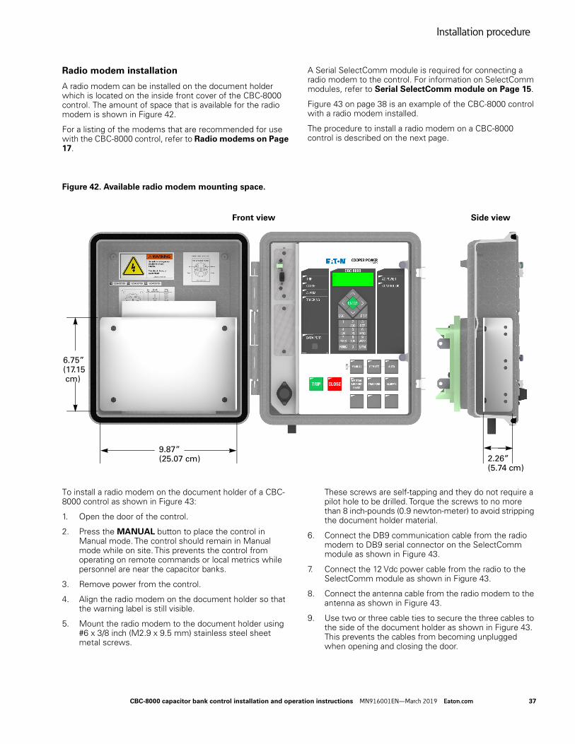
Mounting the control
Mount the control in a convenient, accessible location. Mounting instructions are provided on the following pages.
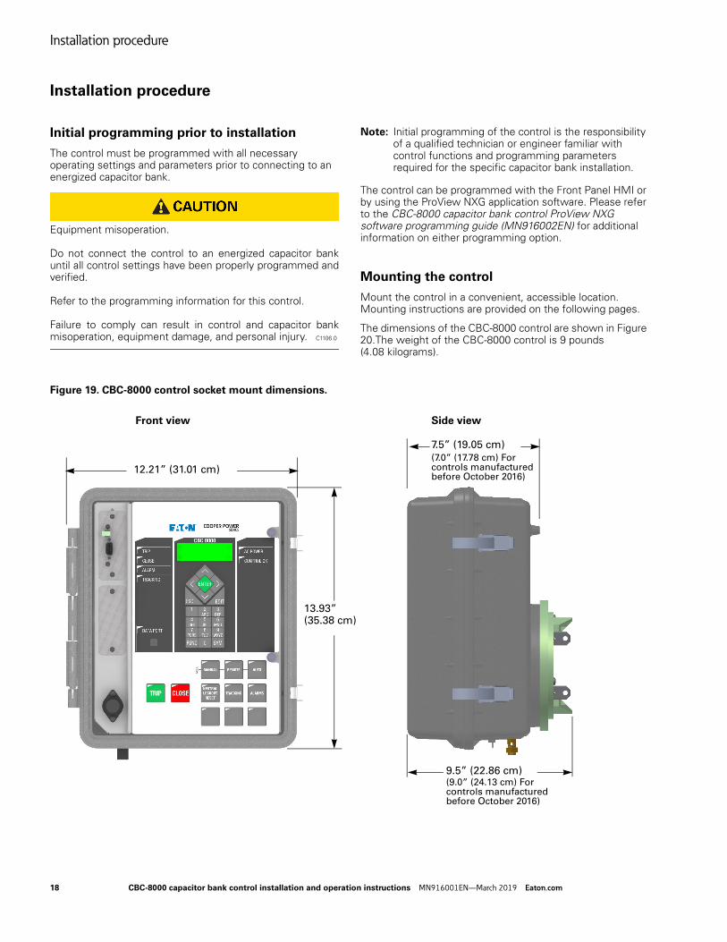
The dimensions of the CBC-8000 control are shown in Figure 20.The weight of the CBC-8000 control is 9 pounds (4.08 kilograms).
Figure 19. CBC-8000 control socket mount dimensions.
12.21” (31.01 cm)
13.93” (35.38 cm)
7.5” (19.05 cm)
9.5” (22.86 cm)
Front view Side view
(7.0” (17.78 cm) For controls manufactured before October 2016)
(9.0” (24.13 cm) For controls manufactured before October 2016)
18 CBC-8000 capacitor bank control installation and operation instructions MN916001EN—March 2019 Eaton.com
Installation procedure
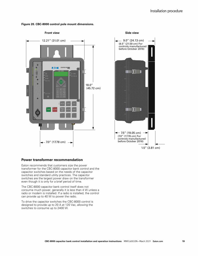
Figure 20. CBC-8000 control pole mount dimensions.
Power transformer recommendation
Eaton recommends that customers size the power transformer for the CBC-8000 capacitor bank control and the capacitor switches based on the needs of the capacitor switches and standard utility practices. The capacitor switches are the largest power draw on the transformer even though it is only for a brief period of time.
The CBC-8000 capacitor bank control itself does not consume much power, generally it is less than 4 W unless a radio or modem is installed. If a radio is installed, the control can provide up to 40 W to power the radio.
To drive the capacitor switches the CBC-8000 control is designed to provide up to 20 A at 120 Vac, allowing the switches to consume up to 2400 W.
12.21” (31.01 cm)
18.0” (45.72 cm)
9.0” (24.13 cm)
1.5” (3.81 cm)
Front view Side view
7.0” (17.78 cm)
7.5” (19.05 cm)
(8.5” (21.59 cm) For controls manufactured before October 2016)
(7.0” (17.78 cm) For controls manufactured before October 2016)
CBC-8000 capacitor bank control installation and operation instructions MN916001EN—March 2019 Eaton.com 19
Installation procedure
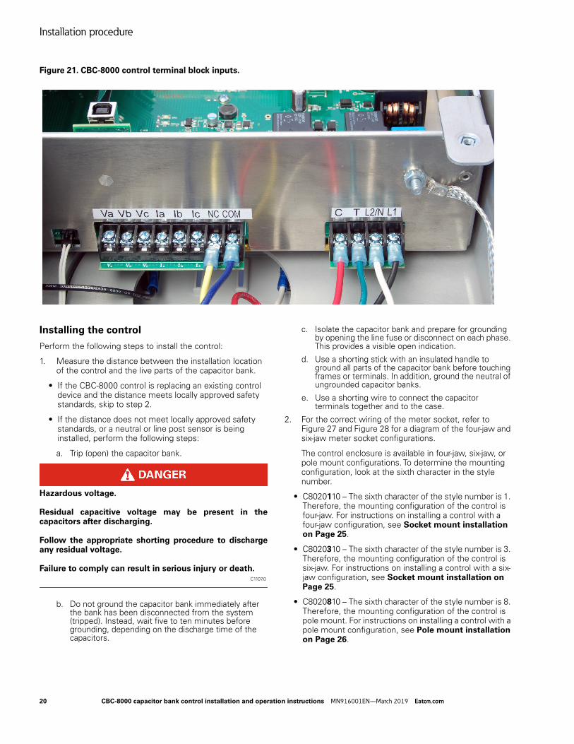
Figure 21. CBC-8000 control terminal block inputs.
Installing the control
Perform the following steps to install the control:
1. Measure the distance between the installation location of the control and the live parts of the capacitor bank.
• If the CBC-8000 control is replacing an existing control device and the distance meets locally approved safety standards, skip to step 2.
• If the distance does not meet locally approved safety standards, or a neutral or line post sensor is being installed, perform the following steps:
a. Trip (open) the capacitor bank.
Hazardous voltage. Residual capacitive voltage may be present in the capacitors after discharging. Follow the appropriate shorting procedure to discharge any residual voltage. Failure to comply can result in serious injury or death.
C1107.0
b. Do not ground the capacitor bank immediately after the bank has been disconnected from the system (tripped). Instead, wait five to ten minutes before grounding, depending on the discharge time of the capacitors.
c. Isolate the capacitor bank and prepare for grounding by opening the line fuse or disconnect on each phase. This provides a visible open indication.
d. Use a shorting stick with an insulated handle to ground all parts of the capacitor bank before touching frames or terminals. In addition, ground the neutral of ungrounded capacitor banks.
e. Use a shorting wire to connect the capacitor terminals together and to the case.
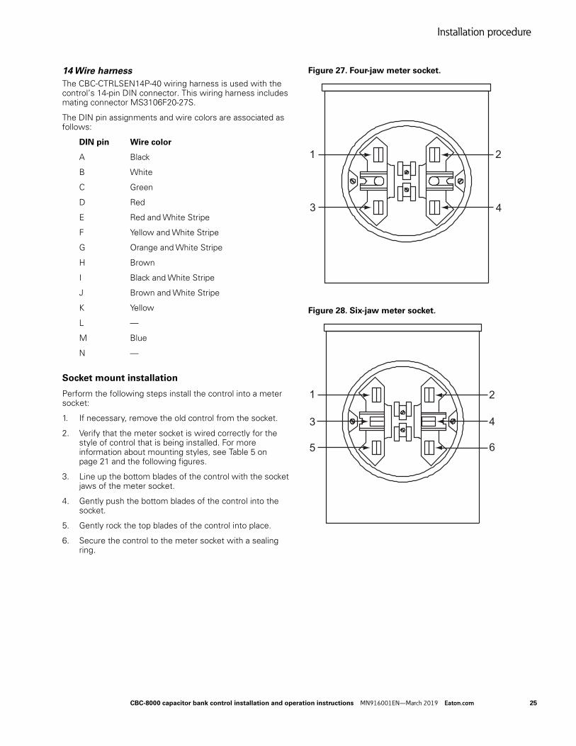
2. For the correct wiring of the meter socket, refer to Figure 27 and Figure 28 for a diagram of the four-jaw and six-jaw meter socket configurations.
The control enclosure is available in four-jaw, six-jaw, or pole mount configurations. To determine the mounting configuration, look at the sixth character in the style number.
• C8020110 – The sixth character of the style number is 1. Therefore, the mounting configuration of the control is four-jaw. For instructions on installing a control with a four-jaw configuration, see Socket mount installation on Page 25.
• C8020310 – The sixth character of the style number is 3. Therefore, the mounting configuration of the control is six-jaw. For instructions on installing a control with a six-jaw configuration, see Socket mount installation on Page 25.
• C8020810 – The sixth character of the style number is 8. Therefore, the mounting configuration of the control is pole mount. For instructions on installing a control with a pole mount configuration, see Pole mount installation on Page 26.
20 CBC-8000 capacitor bank control installation and operation instructions MN916001EN—March 2019 Eaton.com
Installation procedure
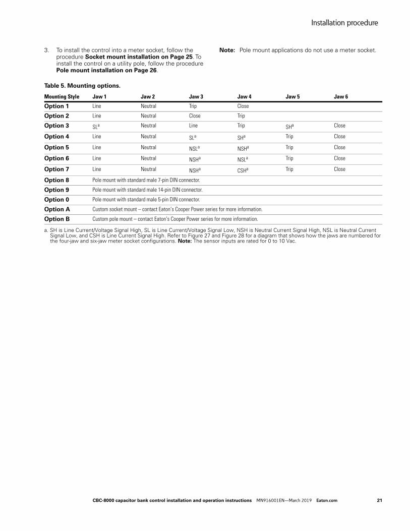
3. To install the control into a meter socket, follow the procedure Socket mount installation on Page 25. To install the control on a utility pole, follow the procedure Pole mount installation on Page 26.
Note: Pole mount applications do not use a meter socket.
Option 8 Pole mount with standard male 7-pin DIN connector.
Option 9 Pole mount with standard male 14-pin DIN connector.
Option 0 Pole mount with standard male 5-pin DIN connector.
Option A Custom socket mount – contact Eaton’s Cooper Power series for more information.
Option B Custom pole mount – contact Eaton’s Cooper Power series for more information.
a. SH is Line Current/Voltage Signal High, SL is Line Current/Voltage Signal Low, NSH is Neutral Current Signal High, NSL is Neutral Current Signal Low, and CSH is Line Current Signal High. Refer to Figure 27 and Figure 28 for a diagram that shows how the jaws are numbered for the four-jaw and six-jaw meter socket configurations. Note: The sensor inputs are rated for 0 to 10 Vac.
CBC-8000 capacitor bank control installation and operation instructions MN916001EN—March 2019 Eaton.com 21
Installation procedure
DIN connector options
Four DIN connector options are available for connecting sensor inputs to the CBC-8000 control:
• 5-Pin DIN Connector (MS3102R16S-8P)
• 7-Pin DIN Connector (MS3102R16S-1P)
• 8-Pin DIN Connector (Sensor Inputs Only; MS3102R20-7P)
• 14-Pin DIN Connector (3-Phase Metering and Control; MS3102R20-27P)
A DIN connector is required to use the CBC-8000 control’s sensor control capabilities.
For information on Eaton’s Cooper Power series wiring harness options, see Wiring harness options on Page 24.
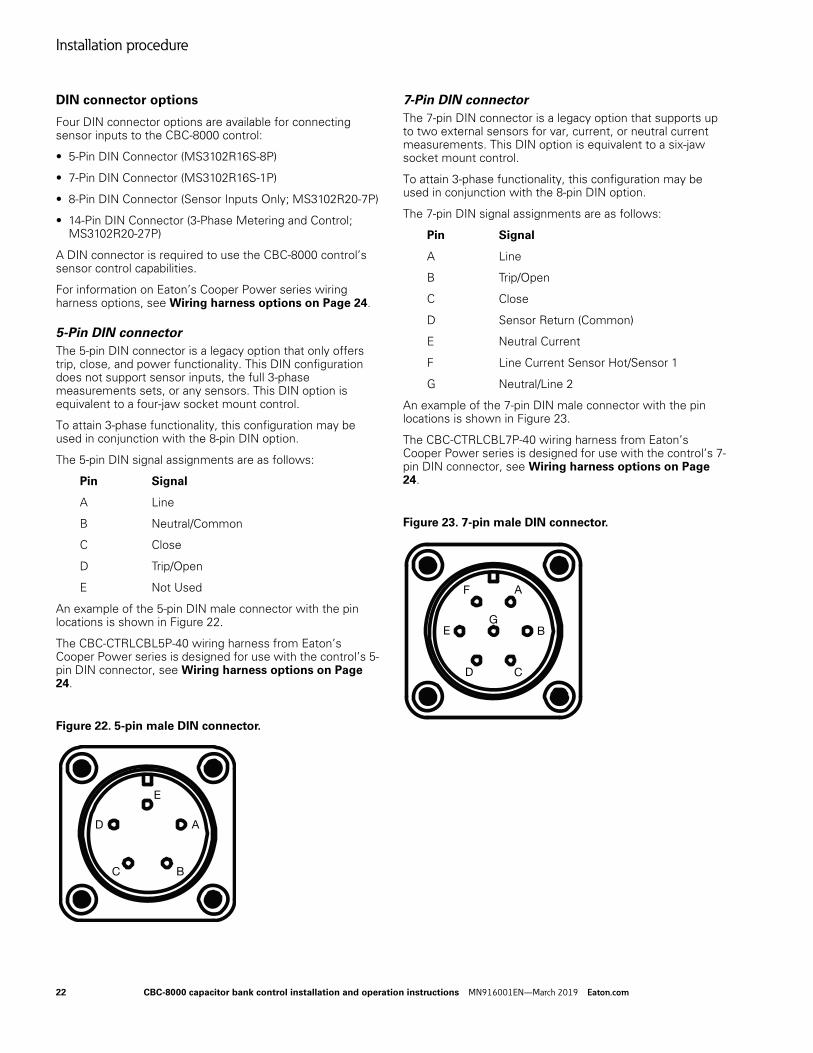
5-Pin DIN connector
The 5-pin DIN connector is a legacy option that only offers trip, close, and power functionality. This DIN configuration does not support sensor inputs, the full 3-phase measurements sets, or any sensors. This DIN option is equivalent to a four-jaw socket mount control.
To attain 3-phase functionality, this configuration may be used in conjunction with the 8-pin DIN option.
The 5-pin DIN signal assignments are as follows:
Pin Signal
A Line
B Neutral/Common
C Close
D Trip/Open
E Not Used
An example of the 5-pin DIN male connector with the pin locations is shown in Figure 22.
The CBC-CTRLCBL5P-40 wiring harness from Eaton’s Cooper Power series is designed for use with the control’s 5-pin DIN connector, see Wiring harness options on Page 24.
Figure 22. 5-pin male DIN connector.
7-Pin DIN connector
The 7-pin DIN connector is a legacy option that supports up to two external sensors for var, current, or neutral current measurements. This DIN option is equivalent to a six-jaw socket mount control.
To attain 3-phase functionality, this configuration may be used in conjunction with the 8-pin DIN option.
The 7-pin DIN signal assignments are as follows:
Pin Signal
A Line
B Trip/Open
C Close
D Sensor Return (Common)
E Neutral Current
F Line Current Sensor Hot/Sensor 1
G Neutral/Line 2
An example of the 7-pin DIN male connector with the pin locations is shown in Figure 23.
The CBC-CTRLCBL7P-40 wiring harness from Eaton’s Cooper Power series is designed for use with the control’s 7-pin DIN connector, see Wiring harness options on Page 24.
Figure 23. 7-pin male DIN connector.
A
BC
D
E
A
B
CD
E
F
G
22 CBC-8000 capacitor bank control installation and operation instructions MN916001EN—March 2019 Eaton.com
Installation procedure
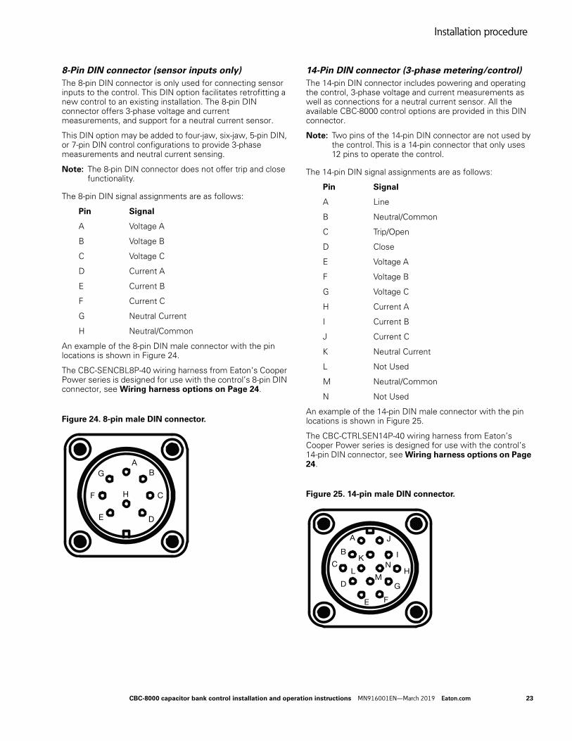
8-Pin DIN connector (sensor inputs only)
The 8-pin DIN connector is only used for connecting sensor inputs to the control. This DIN option facilitates retrofitting a new control to an existing installation. The 8-pin DIN connector offers 3-phase voltage and current measurements, and support for a neutral current sensor.
This DIN option may be added to four-jaw, six-jaw, 5-pin DIN, or 7-pin DIN control configurations to provide 3-phase measurements and neutral current sensing.
Note: The 8-pin DIN connector does not offer trip and close functionality.
The 8-pin DIN signal assignments are as follows:
Pin Signal
A Voltage A
B Voltage B
C Voltage C
D Current A
E Current B
F Current C
G Neutral Current
H Neutral/Common
An example of the 8-pin DIN male connector with the pin locations is shown in Figure 24.
The CBC-SENCBL8P-40 wiring harness from Eaton’s Cooper Power series is designed for use with the control’s 8-pin DIN connector, see Wiring harness options on Page 24.
Figure 24. 8-pin male DIN connector.
14-Pin DIN connector (3-phase metering/control)
The 14-pin DIN connector includes powering and operating the control, 3-phase voltage and current measurements as well as connections for a neutral current sensor. All the available CBC-8000 control options are provided in this DIN connector.
Note: Two pins of the 14-pin DIN connector are not used by the control. This is a 14-pin connector that only uses 12 pins to operate the control.
The 14-pin DIN signal assignments are as follows:
Pin Signal
A Line
B Neutral/Common
C Trip/Open
D Close
E Voltage A
F Voltage B
G Voltage C
H Current A
I Current B
J Current C
K Neutral Current
L Not Used
M Neutral/Common
N Not Used
An example of the 14-pin DIN male connector with the pin locations is shown in Figure 25.
The CBC-CTRLSEN14P-40 wiring harness from Eaton’s Cooper Power series is designed for use with the control’s 14-pin DIN connector, see Wiring harness options on Page 24.
Figure 25. 14-pin male DIN connector.
AB
C
DE
F
G
H
A
B
C
D
E F
G
H
I
J
K
LM
N
CBC-8000 capacitor bank control installation and operation instructions MN916001EN—March 2019 Eaton.com 23
Installation procedure
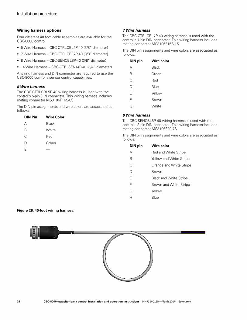
Wiring harness options
Four different 40 foot cable assembles are available for the CBC-8000 control:
A wiring harness and DIN connector are required to use the CBC-8000 control’s sensor control capabilities.
5 Wire harness
The CBC-CTRLCBL5P-40 wiring harness is used with the control’s 5-pin DIN connector. This wiring harness includes mating connector MS3106F16S-8S.
The DIN pin assignments and wire colors are associated as follows:
DIN Pin Wire Color
A Black
B White
C Red
D Green
E —
7 Wire harness
The CBC-CTRLCBL7P-40 wiring harness is used with the control’s 7-pin DIN connector. This wiring harness includes mating connector MS3106F16S-1S.
The DIN pin assignments and wire colors are associated as follows:
DIN pin Wire color
A Black
B Green
C Red
D Blue
E Yellow
F Brown
G White
8 Wire harness
The CBC-SENCBL8P-40 wiring harness is used with the control’s 8-pin DIN connector. This wiring harness includes mating connector MS3106F20-7S.
The DIN pin assignments and wire colors are associated as follows:
DIN pin Wire color
A Red and White Stripe
B Yellow and White Stripe
C Orange and White Stripe
D Brown
E Black and White Stripe
F Brown and White Stripe
G Yellow
H Blue
Figure 26. 40-foot wiring harness.
24 CBC-8000 capacitor bank control installation and operation instructions MN916001EN—March 2019 Eaton.com
Installation procedure
14 Wire harness
The CBC-CTRLSEN14P-40 wiring harness is used with the control’s 14-pin DIN connector. This wiring harness includes mating connector MS3106F20-27S.
The DIN pin assignments and wire colors are associated as follows:
DIN pin Wire color
A Black
B White
C Green
D Red
E Red and White Stripe
F Yellow and White Stripe
G Orange and White Stripe
H Brown
I Black and White Stripe
J Brown and White Stripe
K Yellow
L —
M Blue
N —
Socket mount installation
Perform the following steps install the control into a meter socket:
1. If necessary, remove the old control from the socket.
2. Verify that the meter socket is wired correctly for the style of control that is being installed. For more information about mounting styles, see Table 5 on page 21 and the following figures.
3. Line up the bottom blades of the control with the socket jaws of the meter socket.
4. Gently push the bottom blades of the control into the socket.
5. Gently rock the top blades of the control into place.
6. Secure the control to the meter socket with a sealing ring.
Figure 27. Four-jaw meter socket.
Figure 28. Six-jaw meter socket.
2
4
1
3
1
5
3
2
6
4
CBC-8000 capacitor bank control installation and operation instructions MN916001EN—March 2019 Eaton.com 25
Installation procedure
7. Install an earth grounding wire from the grounding lug, located on the bottom of the control, to the earth following standard industry practices.
The ground resistance should be less than 20 ohms when complete. The grounding wire should be 16 gauge or larger.
The recommended best practice is to install a grounding wire from the CBC grounding lug, located on the bottom of the control, to a common ground point at the top of the capacitor bank rack. A separate or independent grounding wire must run from the capacitor bank rack to the earth following standard industry practices.
Note: The CBC-8000 control is grounded through the ground lug located on the bottom of the control. This ground lug is not tied to the neutral side of the control’s input power (L2/N). Please make sure that the ground lug is tied directly to Earth ground to ensure that the case and internal components are safely grounded.
8. If the control uses a retrofit 8-pin DIN male connector to retrieve 3-phase voltage measurements, current measurements, and neutral current sensing, use a corresponding 8-pin DIN female connector to connect the additional sensors.
Refer to DIN connector options on Page 22 for the signal assignments for the DIN connector pins.
9. Apply power to the control and wait for it to perform a diagnostic test. If the diagnostic test fails, contact your local Eaton’s Cooper Power series representative.
10. Open the cover of the control.
11. Press the MANUAL button to place the control in Manual mode. The control should remain in Manual mode while programming the control on site. This prevents the control from operating on remote commands or local metrics while personnel are near the capacitor banks.
12. Program the control’s clock with the time and date. This can be performed from the front panel (FUNC 064) or by using the ProView NXG application software. When using the front panel, the date is entered in MM-DD-YYYY format and the hour is entered in 24-hour format. Refer to the CBC-8000 capacitor bank control ProView NXG software programming guide (MN916002EN) for detailed procedures.
13. If additional maintenance work needs to be performed in the primary voltage area, such as closing a fuse or replacing a switch, follow your utility company’s standard procedures.
For example:
a. Press the TRIP button on the control to open the capacitor bank.
b. Verify that the capacitor bank tripped open.
c. Open the cutouts on the capacitor bank to disconnect the capacitor bank from high voltage power.
d. Wait a minimum of 5 to 10 minutes, or whatever time is required by your utility training procedures, for the shunt to bleed off.
e. Perform the required maintenance work.
f. When the required work is completed, close the cutouts on the capacitor bank to restore high voltage power to the capacitor bank.
g. Press the CLOSE button on the control to close the capacitor bank.
14. When the work is completed, place the control in Remote or Automatic mode by pressing the REMOTE or AUTO button.
15. Apply a seal to the control and record the serial number of the control and other necessary information.
Pole mount installation
A pole mount bracket is required for pole mount installations and it is included when ordering a pole mount control. Designed for use in all environments, the pole mount bracket is constructed from aluminum alloy 5052-H32.
As shown in Figure 29, the bracket must be installed on the control prior to installing the CBC-8000 control on a pole.
Figure 29. Pole mount bracket installation.
26 CBC-8000 capacitor bank control installation and operation instructions MN916001EN—March 2019 Eaton.com
Installation procedure
Figure 30. Pole mount bracket dimensions in inches. Pole mount bracket installation
Perform the following steps to install the pole mount bracket on the control:
1. Line up the holes in the pole mount bracket with the holes in the CBC enclosure.
2. Secure the pole mount bracket to the CBC enclosure using the supplied screws.
Performing the pole mount installation
Perform the following steps to install the CBC-8000 control on a utility pole:
1. Temporarily place the control in the mounting location and place a mark on the utility pole for the top hole in the pole mount bracket.
2. Install a lag bolt into the pole and hang the control on the pole using the top hole in the pole mount bracket.
3. Install a second lag bolt into the pole through the lower hole in the pole mount bracket.
4. Install an earth grounding wire from the grounding lug, located on the bottom of the control, to the earth following standard industry practices.
The ground resistance should be less than 20 ohms when complete. The grounding wire should be 16 gauge or larger.
The recommended best practice is to install a grounding wire from the CBC grounding lug, located on the bottom of the control, to a common ground point at the top of the capacitor bank rack. A separate or independent grounding wire must run from the capacitor bank rack to the earth following standard industry practices.
Note: The CBC-8000 control is grounded through the ground lug located on the bottom of the control. This ground lug is not tied to the neutral side of the control’s input power (L2/N). Please make sure that the ground lug is tied directly to Earth ground to ensure that the case and internal components are safely grounded.
5. Route the power cable and the control cable from the capacitor bank junction box to the control.
Equipment damage. Do not drill connection holes into the top of the cabinet. Connection holes in the top of the cabinet will allow moisture to seep into the control and damage the components or cause control misoperation. Failure to comply will void the control’s factory warranty. T249.0
6. If the control includes a standard 5-pin, 7-pin or 14-pin DIN male connector for sensor inputs, use a corresponding 5-pin, 7-pin or 14-pin DIN female connector to connect the power and the control cable wires to the control.
CBC-8000 capacitor bank control installation and operation instructions MN916001EN—March 2019 Eaton.com 27
Installation procedure
If a retrofit 8-pin DIN male connector is included, connect the corresponding sensor cable to the control.
Refer to DIN connector options on Page 22 for the signal assignments for the DIN connector pins.
7. Apply power to the control and wait for it to perform a diagnostic test. If the diagnostic test fails, contact your local Eaton’s Cooper Power series representative.
8. Open the cover of the control.
9. Press the MANUAL button to place the control in Manual mode. The control should remain in Manual mode while on site. This prevents the control from operating on remote commands or local metrics while personnel are near the capacitor banks.
10. Program the control’s clock with the time and date. This can be performed from the front panel (FUNC 064) or by using the ProView NXG application software. The date is entered in MM-DD-YYYY format and the hour is entered in 24-hour format. Refer to the CBC-8000 capacitor bank control ProView NXG software programming guide (MN916002EN) for detailed procedures.
11. If additional maintenance work needs to be performed in the primary voltage area, such as closing a fuse or replacing a switch, follow your utility company’s standard procedures. For example:
a. Press the TRIP button on the control to open the capacitor bank.
b. Verify that the capacitor bank tripped open.
c. Open the cutouts on the capacitor bank to disconnect the capacitor bank from high voltage power.
d. Wait a minimum of 5 to 10 minutes, or whatever time is required by your utility training procedures, for the shunt to bleed off.
e. Perform the required maintenance work.
f. When the required work is completed, close the cutouts on the capacitor bank to restore high voltage power to the capacitor bank.
g. Press the CLOSE button on the control to close the capacitor bank.
12. When the work is completed, place the control in Remote or Automatic mode by pressing the REMOTE or AUTO button.
13. Apply a seal to the control and record the serial number of the control and other necessary information.
Panel mount installation
A panel mount bracket is required for surface mount installations. The panel mount bracket is not included when ordering a panel mount control. The panel mount bracket must be ordered separately.
As shown in Figure 31, the bracket must be installed on the control prior to installing the CBC-8000 control on a panel.
Panel mount bracket installation
Perform the following steps to install the panel mount bracket on the control:
1. Line up the holes in the panel mount bracket with the holes in the CBC enclosure.
2. Secure the panel mount bracket to the CBC enclosure using the supplied screws.
Figure 31. Panel mount bracket.
28 CBC-8000 capacitor bank control installation and operation instructions MN916001EN—March 2019 Eaton.com
Installation procedure
Panel mount installation procedure
Perform the following steps to install the CBC-8000 control on a panel:
1. Temporarily place the control in the mounting location and place a mark on the panel for the top holes in the panel mount bracket.
2. Install the upper bolts or screws into the panel and hang the control on the panel using the top holes in the panel mount bracket.
3. Install the lower bolts or screws into the panel through the lower holes in the panel mount bracket.
4. Install an earth grounding wire from the grounding lug, located on the bottom of the control, to the earth following standard industry practices.
The ground resistance should be less than 20 ohms when complete. The grounding wire should be 16 gauge or larger.
The recommended best practice is to install a grounding wire from the CBC grounding lug, located on the bottom of the control, to a common ground point at the top of the capacitor bank rack. A separate or independent grounding wire must run from the capacitor bank rack to the earth following standard industry practices.
Note: The CBC-8000 control is grounded through the ground lug located on the bottom of the control. This ground lug is not tied to the neutral side of the control’s input power (L2/N). Please make sure that the ground lug is tied directly to Earth ground to ensure that the case and internal components are safely grounded.
5. Route the power cable and the control cable from the capacitor bank junction box to the control.
Equipment damage. Do not drill connection holes into the top of the cabinet. Connection holes in the top of the cabinet will allow moisture to seep into the control and damage the components or cause control misoperation. Failure to comply will void the control’s factory warranty. T249.0
6. If the control includes a standard 5-pin, 7-pin or 14-pin DIN male connector for sensor inputs, use a corresponding 5-pin, 7-pin or 14-pin DIN female connector to connect the power and the control cable wires to the control.
If a retrofit 8-pin DIN male connector is included, connect the corresponding sensor cable to the control.
Refer to DIN connector options on Page 22 for the signal assignments for the DIN connector pins.
7. Apply power to the control and wait for it to perform a diagnostic test. If the diagnostic test fails, contact your local Eaton’s Cooper Power series representative.
8. Open the cover of the control.
9. Press the MANUAL button to place the control in Manual mode. The control should remain in Manual mode while on site. This prevents the control from operating on remote commands or local metrics while personnel are near the capacitor banks.
10. Program the control’s clock with the time and date. This can be performed from the front panel (FUNC 064) or by using the ProView NXG application software. The date is entered in MM-DD-YYYY format and the hour is entered in 24-hour format. Refer to the CBC-8000 capacitor bank control ProView NXG software programming guide (MN916002EN) for detailed procedures.
11. If additional maintenance work needs to be performed in the primary voltage area, such as closing a fuse or replacing a switch, follow your utility company’s standard procedures. For example:
a. Press the TRIP button on the control to open the capacitor bank.
b. Verify that the capacitor bank tripped open.
c. Open the cutouts on the capacitor bank to disconnect the capacitor bank from high voltage power.
d. Wait a minimum of 5 to 10 minutes, or whatever time is required by your utility training procedures, for the shunt to bleed off.
e. Perform the required maintenance work.
f. When the required work is completed, close the cutouts on the capacitor bank to restore high voltage power to the capacitor bank.
g. Press the CLOSE button on the control to close the capacitor bank.
12. When the work is completed, place the control in Remote or Automatic mode by pressing the REMOTE or AUTO button.
13. Apply a seal to the control and record the serial number of the control and other necessary information.
CBC-8000 capacitor bank control installation and operation instructions MN916001EN—March 2019 Eaton.com 29
Installation procedure
Cable security sleeve installation
The optional cable security sleeve protects the connections to the control from tampering. The cable security sleeve is installed on the bottom of the control so that it protects the DIN connector and other connections to the control.
The optional cable security sleeve kit (CBC8K-CBLSLEEVE) includes the following parts:
• Cable security sleeve
• Star washers, #8 (4)
• Wing nut, #8-32 (4)
• Template
• Instructions (IL916009EN)
The following tools are required to install the optional security sleeve:
• Drill
• 5/32 inch diameter drill bit
• Masking tape
• Pencil
The dimensions for the security sleeve are provided in the following figure.
Figure 32. Security sleeve dimensions in inches.
Figure 33. Cable security sleeve.
To install the cable security sleeve:
1. Remove any locks that may be securing the CBC-8000 control door latches.
2. Unlatch and open the enclosure door.
3. Press the MANUAL button on the front panel to place the control into Manual mode.
4. Disconnect electrical power from the control.
5. Disconnect the input sensor DIN connector.
6. Disconnect the ground from the control.
7. Loosen the two thumbscrews that secure the front panel cover and open it.
8. As shown in Figure 14 on page 12, apply masking tape to the template and place the template over the bottom of the control.
Note: The cable security sleeve must cover the cable connectors and allow room for the temperature sensor so that the sensor does not interfere with the installation.
30 CBC-8000 capacitor bank control installation and operation instructions MN916001EN—March 2019 Eaton.com
Installation procedure
Figure 34. Template placement
9. Mark the locations to drill each of the four holes required to mount the cable security sleeve.
10. Remove the template from the control.
11. Secure any wiring that may interfere with drilling the holes to prevent wire damage.
12. Using the 5/32 inch bit, carefully drill each of the four holes and clean all the debris out of the enclosure.
13. Align the studs on the cable security sleeve with the holes in the enclosure. The cable security sleeve should sit flush against the enclosure.
14. The DIN cable and any cables will need to be routed through the cable security sleeve and connected to the control before the cable security sleeve is permanently mounted to the control.
15. Route the cables through the cable security sleeve.
16. Connect the DIN cable and any other cables to the control.
17. Slide the cable security sleeve over the cable connections and bring it tight against the enclosure.
18. Install a star washer onto each of the four studs for the cable security sleeve.
19. Install a wing nut onto each of the four studs for the cable security sleeve and tighten.
20. Close the front panel cover and secure it with the thumb screws.
21. Connect the earth ground to the control.
22. Connect electrical power to the control.
23. Place the control in Remote or Automatic mode by pressing the REMOTE or AUTO button.
24. Close the control door and secure the latches.
25. Install utility seals or locks on the control latches.
26. The procedure is completed.
Figure 35. Cable security sleeve installation
CBC-8000 capacitor bank control installation and operation instructions MN916001EN—March 2019 Eaton.com 31
Installation procedure
Storm trapper installation
Eaton recommends installing the optional Storm Trapper™ High Energy (H.E.) low-voltage distribution-class MOV surge arrester between the line and the earth ground for the CBC-8000 control.
The Eaton part numbers for the surge arresters that are recommended for use with a CBC-8000 control are shown in Table 6
Storm Trapper H.E. arresters are designed with a full 40 kA surge withstand capability. This superior energy handling ability assures long service life even in the most severe service conditions.
Figure 36. Storm Trapper High Energy low-voltage distribution-class MOV surge arrester
As shown in Figure 37, the surge arrester black lead is connected to Line and the white lead is connected to Earth Ground.
Refer to the documentation provided with the storm trapper surge arrester for detailed installation instructions.
Figure 37. CBC-8000 control storm trapper surge arrester wiring diagram
Table 6. Storm trapper surge arrester part numbers.
Eaton part number Line voltage
ASZH175C100 120 volt
ASZ350B1 240 volt
Line
Neutral
Line Neutral
Storm Trapper MOV
Surge Arrester
CBC-8000 control
Black wire
White wire
Earth Ground
32 CBC-8000 capacitor bank control installation and operation instructions MN916001EN—March 2019 Eaton.com
Installation procedure
Eaton’s Cooper Power series junction box installation
The junction box facilitates wiring the CBC-8000 control to the capacitor bank switches and sensors. Wiring diagrams for using a Eaton’s Cooper Power series junction box with the CBC-8000 control are shown in Figure 38 on page 33, Figure 39 on page 34 and Figure 40 on page 35.
These wiring diagrams show how to wire a CBC-8000 control to switches and sensors by using one of three different Eaton’s Cooper Power series junction boxes.
For information about wiring line and neutral current sensors to the Eaton’s Cooper Power series junction box, see Table 7 and Table 8.
Equipment damage. The maximum input voltage that can be applied to sensor inputs in the control is 10 V RMS. Failure to comply may result in equipment damage. C1105.0
Table 8 lists the wiring requirements for the neutral current sensor:
Figure 38. CBC-8000 control and Eaton’s single-phase current/neutral current sensor junction box wiring diagram.
Table 7. Line current sensor wiring.
Sensor Wiring
Fisher Pierce Series 1301 N = Green S+ = Black S- = White
Lindsey Multicore Sensor N = Bare S+ = Black S- = Red
Table 8. Neutral current sensor wiring.
Sensor Wiring
Sentran N = N/A S+ = Black S- = White
CBC-8000 capacitor bank control installation and operation instructions MN916001EN—March 2019 Eaton.com 33
Installation procedure
Figure 39. CBC-8000 control and Eaton’s 3-phase multicore voltage/current sensor/neutral current sensor junction box wiring diagram.
34 CBC-8000 capacitor bank control installation and operation instructions MN916001EN—March 2019 Eaton.com
Installation procedure
Figure 40. CBC-8000 control and Eaton’s 3-phase independent voltage/current sensor/neutral current sensor junction box wiring diagram retrofit option.
CBC-8000 capacitor bank control installation and operation instructions MN916001EN—March 2019 Eaton.com 35
Installation procedure
SelectComm module installation
Note: The power to the control must be off when installing or removing SelectComm Modules.
To install either a serial or an Ethernet SelectComm module in a CBC-8000 control:
1. Open the door of the control.
2. Press the MANUAL button to place the control in Manual mode. The control should remain in Manual mode while on site. This prevents the control from operating on remote commands or local metrics while personnel are near the capacitor banks.
3. Remove power from the control.
4. Remove the two screws that attach the upper blank cover to the front panel as shown in Figure 41. Save the #6 (M2.9) sheet metal screws.
5. Remove the blank cover.
6. Insert the SelectComm module into the opening and gently push the module into the connector until it is firmly seated.
7. Insert each of the #6 (M2.9) sheet metal screws and tighten.
8. Apply power to the control.
9. The control will automatically detect that a SelectComm module was installed into the connector and the firmware will allow communications through the module.
10. When the work is completed, place the control in Remote or Automatic mode by pressing the REMOTE or AUTO button.
11. Close the door of the control.
12. Secure the latches.
Figure 41. SelectComm module installation.
Remove the two Screws and the Upper Blank Cover
Insert the SelectComm module and firmly seat the module into the connector. Secure the module with two screws.
36 CBC-8000 capacitor bank control installation and operation instructions MN916001EN—March 2019 Eaton.com
Installation procedure
Radio modem installation
A radio modem can be installed on the document holder which is located on the inside front cover of the CBC-8000 control. The amount of space that is available for the radio modem is shown in Figure 42.
For a listing of the modems that are recommended for use with the CBC-8000 control, refer to Radio modems on Page 17.
A Serial SelectComm module is required for connecting a radio modem to the control. For information on SelectComm modules, refer to Serial SelectComm module on Page 15.
Figure 43 on page 38 is an example of the CBC-8000 control with a radio modem installed.
The procedure to install a radio modem on a CBC-8000 control is described on the next page.
Figure 42. Available radio modem mounting space.
To install a radio modem on the document holder of a CBC-8000 control as shown in Figure 43:
1. Open the door of the control.
2. Press the MANUAL button to place the control in Manual mode. The control should remain in Manual mode while on site. This prevents the control from operating on remote commands or local metrics while personnel are near the capacitor banks.
3. Remove power from the control.
4. Align the radio modem on the document holder so that the warning label is still visible.
5. Mount the radio modem to the document holder using #6 x 3/8 inch (M2.9 x 9.5 mm) stainless steel sheet metal screws.
These screws are self-tapping and they do not require a pilot hole to be drilled. Torque the screws to no more than 8 inch-pounds (0.9 newton-meter) to avoid stripping the document holder material.
6. Connect the DB9 communication cable from the radio modem to DB9 serial connector on the SelectComm module as shown in Figure 43.
7. Connect the 12 Vdc power cable from the radio to the SelectComm module as shown in Figure 43.
8. Connect the antenna cable from the radio modem to the antenna as shown in Figure 43.
9. Use two or three cable ties to secure the three cables to the side of the document holder as shown in Figure 43. This prevents the cables from becoming unplugged when opening and closing the door.
9.87” (25.07 cm)
6.75” (17.15 cm)
2.26” (5.74 cm)
Front view Side view
CBC-8000 capacitor bank control installation and operation instructions MN916001EN—March 2019 Eaton.com 37
Installation procedure
10. Use a cable tie to secure the two cables that are connected to the SelectComm module as shown in Figure 43.
11. Apply power to the control to verify that the radio modem powers up.
12. The radio modem must be configured to communicate with the control using the setup procedure that was provided by the radio modem manufacturer.
13. When the work is completed, place the control in Remote or Automatic mode by pressing the REMOTE or AUTO button.
14. Close the door of the control.
15. Secure the latches.
Figure 43. CBC-8000 with radio modem installed.
Secure Cable Point
Antenna Cable Radio Modem Power Cable SelectComm Module
Radio ModemDocument Holder Communication Cable
Antenna
Cable Tie Down Points
38 CBC-8000 capacitor bank control installation and operation instructions MN916001EN—March 2019 Eaton.com
Installation procedure
Open door hold kit installation
The open door hold will securely hold the door in a fixed, open position while accessing the HMI front panel.
To install the optional open door hold kit:
1. Remove any locks that may be securing the CBC-8000 control door latches.
2. Unlatch and open the enclosure door.
3. Press the MANUAL button on the front panel to place the control into Manual mode.
4. Disconnect electrical power from the control.
5. Remove the screw from the lower right corner of the document holder as shown below. Save the screw as it will be used to secure the open door hold bracket.
Figure 44. Remove document holder screw
6. Orient the open door hold bracket as shown in Figure 45.
7. Align the hole in the back of the open door hold bracket with the hole in the document holder. This is the hole that you removed the screw from in step 5.
8. Re-install the document holder screw to secure the bracket to the document holder.
9. Install the #4 x 1/4 inch pan head sheet metal screw to secure the bracket to the flange (side) of the document holder as shown below.
Note: The sheet metal screw is self-tapping and it does not utilize any existing holes.
Figure 45. Open door hold bracket installation
10. Loosen the two thumbscrews that secure the front panel cover and open it.
Figure 46. Front panel thumbscrews
11. If your control has an existing hole for the open door hold stud, continue with step 14 on page 40.
12. If you have an older control, you will need to drill a hole for the stud in the location that is shown in Figure 47 on page 40.
Inside the control, ensure that all the wires are cleared away from the door jamb.
Using a 5/32 inch diameter drill bit, drill a hole for the mounting stud according to the specifications in Figure 47 on page 40.
Loosen each thumbscrewand open the front panel
Existing stud hole
CBC-8000 capacitor bank control installation and operation instructions MN916001EN—March 2019 Eaton.com 39
Installation procedure
13. Deburr the edges and remove any debris from the inside of the control.
Figure 47. Stud hole drill location in inches
14. Remove the two screws that attach the fuse holder to the control. Pull the fuse holder out of the mounting hole and move it away from the opening. This will allow you to access the standoff on the back surface of the enclosure with a screwdriver.
Figure 48. Fuse holder removal
15. Orient the stiffening bracket and install it in the control. Align the hole in the stiffening bracket with the standoff on the back of the enclosure. Ensure that the hole at the other end of the bracket aligns with the hole in the sheet metal door jam.
16. Use the tread-forming, #8-16 x 3/8 inch screw to secure the stiffening bracket to the standoff at the back of the enclosure. Insert the Phillips screwdriver through the fuse holder opening to tighten the screw.
Figure 49. Stiffening bracket installation
17. Assemble the truss head screw, shoulder washer and KEPS lock nut as shown in Figure 49.The KEPS nut lock washer should be pointing away from the shoulder washer. Finger tighten the nut to press the shoulder washer against the underside of the truss head screw.
18. Align the hole in the free end of the stiffening bracket with the hole in the door jam, thread the truss head screw assembly into the PEM nut in the stiffening bracket and lightly tighten.
19. Using a wrench, tighten the KEPS nut to the stiffening bracket.
Figure 16. Installation complete
20. Re-assemble the fuse holder ensuring that the wires fold nicely behind the door jam and do not get pinched. Install the two screws and tighten.
21. Test the open door hold. The bracket will attach to the stud and securely hold the control door open.
22. Close the front panel cover and secure it with the thumb screws.
23. Connect electrical power to the control.
24. Place the control in Remote or Automatic mode by pressing the REMOTE or AUTO button.
25. Close the control door and secure the latches.
26. Install utility seals or locks on the control latches to complete the procedure.
40 CBC-8000 capacitor bank control installation and operation instructions MN916001EN—March 2019 Eaton.com
Installation procedure
Before placing the control into service
Prior to placing the control into service, the following installation procedures must be properly completed and verified:
Equipment misoperation. Do not connect the control to an energized capacitor bank until all control settings have been properly programmed and verified. Refer to the programming information for this control. Failure to comply can result in control and capacitor bank misoperation, equipment damage, and personal injury. C1106.0
1. Verify that the control is properly mounted.
2. Verify that the capacitor bank is installed according to all locally approved standards and practices.
3. Verify that ac disconnect switches are installed.
4. Verify that the control and the neutral of the capacitor bank are properly grounded.
Note: The CBC-8000 control is grounded through the ground lug located on the bottom of the control. This ground lug is not tied to the neutral side of the control’s input power (L2/N). Please make sure that the ground lug is tied directly to Earth ground to ensure that the case and internal components are safely grounded.
5. Verify that the cable between the control and the capacitor bank is properly connected and supported.
6. Turn on the ac power to the control.
Note: The control includes a feature that will turn off the backlit LCD display after 5 minutes of inactivity at the front panel (no buttons pressed). Pressing any button on the front panel will turn on the LCD display backlight.
7. Verify that all of control programming parameters are correctly entered.
Note: Refer to Service Information CBC-8000 capacitor bank control ProView NXG software programming guide (MN916002EN) for additional information.
8. Set the control clock to the correct time. The real-time clock will maintain its time for approximately 3 days when power is lost.
Note: Refer to the CBC-8000 capacitor bank control ProView NXG software programming guide (MN916002EN) for additional information.
CBC-8000 capacitor bank control installation and operation instructions MN916001EN—March 2019 Eaton.com 41
Testing
Testing
Explosion hazard. Move a safe distance away from the capacitor bank after pressing the CLOSE button on the control. Failure to do so may result in severe personal injury or death. C1104.0
Explosion hazard. Move a safe distance away from the capacitor bank after pressing the TRIP button on the control. Failure to do so may result in severe personal injury or death. C1103.0
Testing an installed control
Perform the following steps to verify that the control is operating properly:
1. Verify the capacitor bank is tripped (open).
2. Open the door of the control.
3. Verify that the control front panel is operating by pressing any button to reactivate the backlit LCD display.
4. Check the operational values for currents, voltages, and other metering information.
Note: Scroll through the LCD display messages by pressing the (Up) arrow and (Down) arrow underneath the LCD display on the programming panel.
5. Verify that the ac POWER LED is illuminated on the control operator panel. This LED indicates the presence of ac power (Figure 7).
6. Verify that the CONTROL OK LED is illuminated on the control operator panel.
Note: The control includes a feature that turns off the backlit LCD display after 5 minutes of inactivity at the front panel (no buttons pressed). Pressing any button on the front panel will turn the LCD backlight on.
7. Press the MANUAL button on the front panel to place the control in Manual mode.
8. Press the CLOSE button to close the capacitor bank.
9. Verify that the capacitor bank is closed.
10. If the capacitor bank closed correctly, press the TRIP button to trip the capacitor bank.
11. Verify that the capacitor bank is tripped (open).
12. Leave the capacitor bank tripped and press the REMOTE or AUTO button on the front panel to place the control into Remote or Automatic mode.
13. Close the door of the control and secure the latch.
Removing the control from service
The control can be taken out of service and placed back into service without de-energizing the capacitor bank and interrupting the system. However, during the time the control is out of service, the capacitor bank is inoperative.
The following sections describe how to remove the CBC-8000 control from service:
• Removing a socket mount control from service
• Removing a pole mount control from service
• Removing a panel mount control from service
Removing a socket mount control from service
Perform the following steps to remove a socket mount control from service:
1. Open the door of the control.
2. Press the MANUAL button on the front panel to place the control in Manual mode.
3. Press the TRIP button to trip (open) the capacitor bank.
Explosion hazard. Move a safe distance away from the capacitor bank after pressing the TRIP button on the control. Failure to do so may result in severe personal injury or death. C1103.0
4. Verify that the capacitor bank is tripped (open).
5. Disconnect power from the control.
6. If the control is connected to an external communication device, disconnect the communication cable from the SelectComm communication module.
7. Gently pull on the top of the control to disconnect the top blades from the socket.
8. Gently pull on the bottom of the control to disconnect the bottom blades from the socket.
42 CBC-8000 capacitor bank control installation and operation instructions MN916001EN—March 2019 Eaton.com
Testing
9. If the control is not to be replaced with another control, disconnect the power to the meter socket and control cables.
10. Carefully transport the control to a suitable service facility.
Removing a pole mount control from service
Perform the following steps to remove a pole mount control from service:
1. Open the door of the control.
2. Press the MANUAL button on the front panel to place the control in Manual mode.
3. Press the TRIP button to trip (open) the capacitor bank.
Explosion hazard. Move a safe distance away from the capacitor bank after pressing the TRIP button on the control. Failure to do so may result in severe personal injury or death. C1103.0
4. Verify that the capacitor bank is tripped (open).
5. Disconnect power from the control.
6. If the control is connected to an external communication device, disconnect the communication cable from the SelectComm communication module.
7. Remove the lower lag bolt that is attaching the control bracket to the pole.
8. Loosen the upper lag bolt that is attaching the control bracket to the pole.
9. Gently lift the control off of the upper lag bolt and remove from the pole.
10. If the control is not to be replaced with another control, disconnect the power to the control cables.
11. Carefully transport the control to a suitable service facility.
Removing a panel mount control from service
Perform the following steps to remove a panel mount control from service:
1. Open the door of the control.
2. Press the MANUAL button on the front panel to place the control in Manual mode.
3. Press the TRIP button to trip (open) the capacitor bank.
Explosion hazard. Move a safe distance away from the capacitor bank after pressing the TRIP button on the control. Failure to do so may result in severe personal injury or death. C1103.0
4. Verify that the capacitor bank is tripped (open).
5. Disconnect power from the control.
6. If the control is connected to an external communication device, disconnect the communication cable from the SelectComm communication module.
7. Remove the lower screws or bolts that are attaching the panel mount bracket to the surface.
8. Loosen the upper screws or bolts that are attaching the control bracket to the surface.
9. Gently lift the control off of the upper screws or bolts and remove from the surface.
10. If the control is not to be replaced with another control, disconnect the power to the control cables.
11. Carefully transport the control to a suitable service facility.
CBC-8000 capacitor bank control installation and operation instructions MN916001EN—March 2019 Eaton.com 43
Approved sensor manufacturers
Approved sensor manufacturers
The CBC-8000 control supports measurements from optical sensors, line post and neutral current sensors.
The sensor inputs for the control are rated for 0 to 10 Vac.
Note: If you are using a sensor that is not on the approved list, refer to the Communications Point Data Base (TD916002EN) for proper impedance programming.
GridAdvisor optical sensor
Eaton’s GridAdvisor optical medium-voltage and current sensor system uses an all-optical measurement platform for unparalleled accuracy and precision of both voltage and current across multiple voltage classes.
Available in a variety of easy-to-install packages with a standardized interface, Eaton’s optical sensors are the ideal solution to retrieve real-time site metrology and intelligence on your electrical distribution system, substations and underground distribution locations.
The CBC-8000 M410 Optical Sensor Field kit (PN CBC8K-M410-KIT) is available for connecting the CBC-8000 control to the M410 optical sensor system and it includes the following parts:
• CBC-8000 control SelectComm Ethernet card (13.7 Vdc, 3 A continuous power supply)
• Two 3/4 inch cord grips
• Ethernet cable, 8 foot with UV jacket for outdoor use
• Power cable, 8 foot with UV jacket for outdoor use
Eaton’s optical sensors offer voltage and current accuracy of ±0.5% with no loss of accuracy or precision over the entire measurement and temperature range.
This optical sensor solution enables better characterization of fault events for improved reliability, better understanding of the impacts of renewables and Distributed Energy Resources, and increased efficiencies and savings from Volt-var control programs.
The following GridAdvisor optical sensor models are available for use with the M410 GridAdvisor optical system processor:
• RG235 GridAdvisor optical hanging overhead voltage and current sensor, 4 to 35 kV
• RE120 GridAdvisor optical deadbreak elbow voltage sensor, 200 A
• RE160 GridAdvisor optical deadbreak elbow voltage sensor, 600 A
• RI125 GridAdvisor optical standoff insulator voltage sensor, 4 to 25 kV
For additional information on GridAdvisor optical sensors, see Eaton’s Web site (Eaton.com) or contact your local Eaton representative.
Line post sensor
Line post sensors provide the means to provide accurate and reliable current measurements to the CBC-8000 control.
The following sensors have been tested for use with the control:
• Fisher Pierce Series 1301A
• Lindsey Multicore Sensor
The CBC-8000 control’s analog inputs are designed to provide the best possible accuracy over the entire 10 Vac rang; however, certain sensor designs can draw power from the control’s measurement circuitry in such a way that measurements close to the maximum 10 Vac are no longer possible. While no damage will occur to either the control’s inputs or to the sensor, at over 9 Vac with certain sensors you may see harmonic measurements that are not actually present due to signal clipping. The recommended Lindsey and Fisher Pierce sensors do not have this issue. Sensors that may experience this issue remain highly accurate at values at or below 9 Vac.
Neutral current sensor
The optional CBC-NCSENSOR-35 and CBC-NCSENSOR8P-35 current transducers by Eaton’s Cooper Power series are designed for indoor and outdoor use. All components are waterproof, including the core material and drain holes are provided in the housing.
The CBC-NCSENSOR8P-35 offers a neutral current sensor, wiring harness and 8-pin DIN connector. This assembly is connected to the control with the 8-pin DIN connector that is described in 8-Pin DIN connector (sensor inputs only) on Page 23.
The CBC-NCSENSOR-35 sensor comes with a 35 foot twisted-pair 18 AWG cable with pigtails. The cable may be connected to the neutral current input of a junction box, or routed to the meter base for socket mount controls.
The neutral current sensor specifications are listed in Table 9 on page 45.
44 CBC-8000 capacitor bank control installation and operation instructions MN916001EN—March 2019 Eaton.com
Approved sensor manufacturers
Fisher Pierce AT929 Neutral Current sensor. If you are installing the Fisher Pierce AT929 Neutral Current sensor, Eaton recommends adding a 100 Ohm resistor between the NC input and the COM input on the terminal block (see Figure 21 on page 20) inside the CBC-8000 control to obtain the correct voltage potential between the two signals. Adding the 100 Ohm burden resister greatly improves the accuracy of the CT in the AT929 sensor. In addition, set the Neutral Current Ratio to 52.8 instead of 60 in the CBC-8000 control. This setting change can be made from the front panel HMI or with the ProView NXG application software. The actual value, based on measurements with the resister installed, can determined by calibrating the control. For information on calibrating the CBC-8000 control, the front panel HMI or on the ProView NXG application software, refer to the CBC-8000 capacitor bank control ProView NXG software programming guide (MN916002EN).
Figure 50. CBC-NCSENSOR-35 neutral current sensor. Optical sensor signal processor installation
This procedure provides a general outline of the steps that are required to connect Eaton’s M410 GridAdvisor optical signal processor or a third-party signal processor to the CBC-8000 control:
1. Before you are on-site, it is recommended to install a grounding lug in the enclosure for the signal processor and to remove the cable entry frame from the enclosure.
2. Mount the enclosure with the M410 GridAdvisor optical signal processor installed inside to the distribution pole. Follow the enclosure mounting instructions in the GridAdvisor optical sensor installation guide.
Note: Do not block the M410 vents or restrict the airflow from coming through the vents.
3. Open the door of the control.
4. Press the MANUAL button to place the control in Manual mode. The control should remain in Manual mode while on site. This prevents the control from operating on remote commands or local metrics while personnel are near the capacitor banks.
5. Disconnect power from the CBC-8000 control.
6. Install the SelectComm Ethernet module as described in SelectComm module installation on Page 36.
7. Install two cord grips in the CBC-8000 control’s enclosure. One cord grip is for the Ethernet cable and the other is for the signal processor’s power cable.
8. Route the Ethernet cable, with a UV jacket for outdoor use, through the cord grip and connect it to the SelectComm Ethernet module.
Table 9. Neutral current sensor specifications.
Spec Value
Size 3.8” W x 3.3” H x 1” D, 1.25" window (9.65 cm W x 8.38 cm H x 2.54 cm D, 3.18 cm window)
Current range 50 A ±1% over the range of 0.5 A to 50 A calibrated to 0.5% full
Over current 100 A continuously will not harm the CT – no dc allowed
Voltage range 600 Vac tested using 2500 Vac for up to 1 minute
Bandwidth 10 Hz to 5000 Hz
Output voltage 10 Vac at 100 A input
Output limiting Set by internal resistor and windings – will saturate without harm
Phase displacement Approximately 1 degree leading or lagging the input current
Power factor Any load current power factor from 0.5 to 1.0 lead or lag
Temperature range -50° F to 185° F (-46° C to 85° C)
Temperature Response
Less than 0.05% from -4° F to 185° F (-20° C to 85° C)
Input sensor ratio 10:1
CBC-8000 capacitor bank control installation and operation instructions MN916001EN—March 2019 Eaton.com 45
Approved sensor manufacturers
9. Route the power cable, with a UV jacket for outdoor use, through the cord grip and connect it to the SelectComm Ethernet module’s Vdc power output.
10. Mount the enclosure for the signal processor near the CBC-8000 control so that the cables can easily be routed between the control and the device(s) in the enclosure.
11. Route the Ethernet and the power cables into the enclosure for the signal processor.
12. Connect the Ethernet cable to the signal processor.
13. Connect the power cable to the M410 signal processor.
14. Remove the Eaton GridAdvisor optical sensor from the shipping container. When unpacking the sensor, do not pick it up by the cable as it may break. Keep the connector in its packaging until it is ready to be installed. This will protect the connector from potential contact with the ground or wet surfaces.
Note: Refer to the installation instructions that were provided with your sensor(s) for detailed installation directions.
15. Before each sensor is installed, apply power to the control and the signal processor and plug the sensor into the signal processor to visually confirm that the status lights for that bay are activated and that the processor and sensor are functional.
16. As each sensor is hung or installed, ensure that they are grounded.
17. When finished installing the sensors, close and secure the door of the M41signal processor enclosure.
18. Close and secure the door of the control.
19. Restore power to the CBC-8000 control.
20. Press the REMOTE or AUTO button to take the control out of Manual mode.
21. Perform local and remote testing to verify that the installation is functioning as expected.
46 CBC-8000 capacitor bank control installation and operation instructions MN916001EN—March 2019 Eaton.com
Additional information
Additional information
This equipment requires routine inspection and maintenance to ensure proper operation. If it is not maintained, it can fail to operate properly. Improper operation can cause equipment damage and possible personal injury. G105.1
Replacement kits
Replacement kits for the control are available through the factory Service Department. To order these kits, refer to the Replacement Parts price list for catalog numbers and pricing. Contact your local Eaton representative for additional information and order procedures.
Factory-authorized service centers
Factory-authorized service centers are located throughout the continental United States and the world to provide maintenance, repair, and testing services for Eaton’s Cooper Power series controls. For more information, contact your local Eaton representative.
CBC-8000 capacitor bank control installation and operation instructions MN916001EN—March 2019 Eaton.com 47
Additional information
48 CBC-8000 capacitor bank control installation and operation instructions MN916001EN—March 2019 Eaton.com
Eaton is dedicated to ensuring that reliable, efficient and safe power is available when it’s needed most. With unparalleled knowledge of electrical power management across industries, experts at Eaton deliver customized, integrated solutions to solve our customers’ most critical challenges.
Our focus is on delivering the right solution for the application. But, decision makers demand more than just innovative products. They turn to Eaton for an unwavering commitment to personal support that makes customer success a top priority. For more information, visit Eaton.com.
Eaton, Cooper Power and ProView NXG application software are valuable trademarks of Eaton in the U.S. and other countries. You are not permitted to use these trademarks without the prior written consent of Eaton.
All other trademarks are property of their respective owners.
For Eaton’s Cooper Power series CBC-8000 control product information call 1-877-277-4636 or visit: Eaton.com.