70
CD 3101 Power Unit North America 92-12-0311A Operating Manual 2010

CD 3101Power Unit
North America92-12-0311A
Operating Manual
2010

iiii CD 3101 Order No. BA 92-12-0311A Issue 22.02.10
CD 3101 Operating Manual, Issue 02/2010 Order No. BA 92-12-0311A
Translation of the Operating Manual
Customer Service in Germany:
HBS Bolzenschweiss-Systeme GmbH & Co. KGFelix-Wankel-Strasse 1885221 Dachau / Germany
Phone +49 (0) 8131 511-0Fax +49 (0) 8131 511-100E-mail [email protected] www.hbs-info.com
Copyright:The information contained herein may not be copied, reproduced, adapted,merged, translated or used without the prior written consent of the copyrightowner.
Adaptations, errors and technical modifications reserved without prior notice.
© HBS Bolzenschweiss-Systeme GmbH & Co. KG

iiiCD 3101 Order No. BA 92-12-0311A Issue 22.02.10 iii
Dear customer,
Thank you very much for purchasing a power unit from HBS Bolzenschweiss-Systeme.
We from HBS wish you always successful working with this stud welding unit.
We ask you to observe the following points:
– Store the operating manual in a way that it can always be accessed by theoperator.
– Let the operator sign before starting up that he has read and completely under-stood the operating manual.
– This operating manual applies only to this stud welding unit.– Protect the stud welding unit from unauthorized use.– The stud welding unit must only be operated by trained personnel.– Let an electrician check whether the wall sockets where you want to connect the
related stud welding unit, are properly fused and grounded.– Inform our customer service in case of malfunction.– In case of accident, inform a physician and the responsible official body.
THREAT TO LIFE!Persons fitted with a pace maker must not operate the stud
welding machine.
MAGNETIC FIELDS!During stud welding, strong electro-magnetic fields aregenerated. Do not weld in the vicinity of the electrical
equipment which could be affected.
Safety instructions are a delicate subject. Anybody who handles a stud weldingunit, whether it is the welding gun or the power unit, should be familiar with them,because improper use of stud welding units can be dangerous to life.
For your own sake you should know the safety instructions for operating your HBSstud welding units inside out.
In addition to the protection of your health and the capital value of the enterprise, thesafety instructions are intended to clarify any responsibilities, which arise fromownership and operation of the equipment.
This chapter of the operating manual offers you clear and easy to understand informationfor the safe operation of your HBS stud welding unit.

iviv CD 3101 Order No. BA 92-12-0311A Issue 22.02.10
Your power unit may differ in some details from the captions in this manual. This hasno effect on the operation of the welding machine.
Should you have questions about this manual or in case you want to order some morecopies, please provide the order number listed in the foot line.
Important reminder:
Data and information herein were collected with greatest care. Although we did our verybest to correctly update any information up to the time of delivery, there is no guaranteein respect of errors.
If you should detect errors or mistakes right in this manual, please contact us:
HBS Bolzenschweiss-Systeme GmbH & Co. KG
Felix-Wankel-Strasse 18
85221 Dachau / Germany
A feedback blank is provided in the appendix.

CD 3101 Order No. BA 92-12-0311A Issue 22.02.10 v
Table of Contents
Table of Contents
1 General ............................................................................................. 71.1 Guide to this Operating Manual .................................................................... 8
1.2 Safety Symbols ............................................................................................ 9
1.3 General Safety Instructions ........................................................................ 10
1.4 Intended Use .............................................................................................. 10
1.5 Transportation, Packaging, Storage ........................................................... 11
1.6 Accompanying Documents ........................................................................ 11
1.7 Markings ..................................................................................................... 12
2 Delivery ........................................................................................... 13
3 Starting-up ..................................................................................... 143.1 Requirements of Workplace ...................................................................... 14
3.2 Connecting the Power Unit to the Primary Power Supply .......................... 15
3.3 Connecting the Welding Gun to the Power Unit ......................................... 16
3.4 Ground Connection .................................................................................... 17
3.5 Change Working Place .............................................................................. 17
4 Function ......................................................................................... 184.1 Components of the Power Unit .................................................................. 18
4.2 Keyboard and Display ................................................................................ 18
5 Stud Welding Procedure ............................................................... 195.1 Safety Instructions ...................................................................................... 19
5.2 Functional Principle of Stud Welding .......................................................... 225.2.1 Contact Stud Welding ............................................................................................ 225.2.2 Gap Stud Welding .................................................................................................. 23
5.3 Welding Preparation ................................................................................... 24
5.4 High-strength Welds................................................................................... 24
5.5 Determination of Welding Parameters ....................................................... 24
5.6 Switching on the Power Unit ...................................................................... 265.6.1 Adjusting the Charging Voltage of Capacitors ......................................................... 275.6.2 Library Mode .......................................................................................................... 28
5.7 Welding Procedure .................................................................................... 28

vi CD 3101 Order No. BA 92-12-0311A Issue 22.02.10
Table of Contents
5.8 Checking the Quality of the Weld ............................................................... 305.8.1 Visual Inspection ................................................................................................... 305.8.2 Bending Test .......................................................................................................... 315.8.3 Arc Blow Effect ...................................................................................................... 33
5.9 Malfunctions and Corrective Actions .......................................................... 34
5.10 Welding Elements ...................................................................................... 35
6 Switching off the Power Unit ........................................................ 376.1 Temporary Switching off ............................................................................. 37
6.2 Disposal ..................................................................................................... 37
7 Care and Maintenance .................................................................. 387.1 Safety Instructions ...................................................................................... 38
7.2 Regular Maintenance Operations ............................................................... 38
7.3 Tools to be Used ......................................................................................... 38
7.4 Open the Power Unit .................................................................................. 39
8 Appendix ........................................................................................ 418.1 Technical Data ............................................................................................ 41
8.2 Spare Parts ................................................................................................ 42
8.3 Circuit Diagram .......................................................................................... 56
8.4 Environmentally Admissible Disposal ......................................................... 57
Glossary ......................................................................................... 58
Regulations and Standards .......................................................... 59
Further Instructions ....................................................................... 61
Guarantee Clauses ........................................................................ 62
Confirmation .................................................................................. 63
Feedback ........................................................................................ 64
Service & Support ......................................................................... 65
Index ............................................................................................... 66

CD 3101 Order No. BA 92-12-0311A Issue 22.02.10 7
1 General
Persons addressed by this operating manualThis operating manual is written for operators, personnel of the end user, and authorizedservice technicians. It provides you with all necessary information to operate the powerunit.
Required user qualificationThe power unit must only be operated by qualified personnel.
Let the power unit only be operated by persons who
– are qualified through a suitable training according to the current standards (seeappendix),
– are properly instructed,
– are physically and intellectually suitable,
– can be expected to reliably fulfill the requested job.
What else must the owner observe?Make sure that this operating manual is always in reach of the stud welding unit.Read the entire manual before operating the power unit.Strictly observe the safety instructions.Before starting up the power unit, let the operator sign the confirmation that he/she has read and fully understood the operating manual (see appendix).Do not commence stud welding until you have understood all operatingprocesses.Contact us if there are any doubts on certain operating procedures.
Protect the power unit against unauthorized use.Inform our service in case of malfunction.
Based on this operating manual, a company specific work order, as well as a companyspecific maintenance instruction must be drawn up. The company specific work ordermust consider the special user conditions in your company.
Make sure that operators of the welder are provided with and wear personal protectiveequipment, e.g. protective goggles, gloves, shoes, ear protection etc.
Owners and operators make sure that the power unit is only used as directed.
During any activity such as transportation, set-up, (re-)assembly, production,maintenance etc. observe the information given in this operating manual.
1 General

8 CD 3101 Order No. BA 92-12-0311A Issue 22.02.10
1.1 Guide to this Operating Manual
This operating manual provides you with the following information"Delivery" in Chapter 2"Starting-up" in Chapter 3"Functional Principle" in Chapter 4"Stud Welding Process" in Chapter 5"Switching off the Power Unit" in Chapter 6"Care and Maintenance" in Chapter 7Technical Data and much more in Appendix
THREAT TO LIFE and risk of serious health and material damage incase of improper use of the power unit. Observe all notes in thisoperating manual.
Note for qualified operators (see chapter 1).
All instructions contained in this manual must also be observedby qualified operators.
The welding process and the sequence of procedures to carryout a weld are described in chapter 5.
1 General
1.1 Guide to this Operating Manual

CD 3101 Order No. BA 92-12-0311A Issue 22.02.10 9
1.2 Safety Symbols
Symbols and markings used in this operating manual mean:
Threat to life or risk of personal injury
Risk of material damage
Ban for persons fitted with a pace maker
Warning of dangerous electrical voltage
Warning of electromagnetic fields
Wear protective clothes
Wear protective goggles
Wear ear protection
Additional tips for operation and service safety
Prompt
– List
1 General
1.2 Safety Symbols

10 CD 3101 Order No. BA 92-12-0311A Issue 22.02.10
1.3 General Safety Instructions
Improper operation of the power unit is LIFE-THREATENING!Threat to life– by electric shock and arc– by toxic vapors and airborne particles– by red-hot metal spatters (fire risk)– by blow-up of explosive gases and materials– by strong magnetic fields for persons fitted with a pace makerIn addition, through improper use damage to the stud welding unitand to material can be caused. For details, see chapters 1, 3 and 5.
1.4 Intended Use
Warning: Unauthorized interference with the stud welding unitas well as unauthorized alteration of the stud welding unit areprohibited and result in complete cancellation of any guaranteeand liability claims against HBS.
Operation of the power unit is only allowed with HBS weldingguns, this clause is also part of ”use as directed”.
The power unit is intended to weld welding elements according to actual standards (seechapter 5 and appendix). Any other use is regarded as not used as directed. Themanufacturer is not liable for damages resulting from the stud welding unit not used asdirected. Any risk is carried by the user.
The power unit is designed according to specific standards and accident preventionregulations. Basics are European Union guidelines and in Germany valid standards.Please note that in your country additional standards and safety conditions (especiallyrules for accident prevention) may differ from the standards mentioned in this operatingmanual. The power unit was manufactured to the latest developments in technology andis regarded as safe to operate (place of operation see section 8.1).
The welding guns C 08 and CA 08 can be connected to the HBS power unitCD 3101. For details please contact the HBS customer service (address see page ii).
Check in any case the operating manual of the HBS welding gun whether thispower unit can be used.
Observing the operating manual of the used welding gun is also part of the ”use asdirected”.
1 General
1.3 General Safety Instructions

CD 3101 Order No. BA 92-12-0311A Issue 22.02.10 11
1.5 Transportation, Packaging, Storage
HBS delivers products in a specific transport package.
Save the undamaged packing. Ship and transport the device only in its originalpacking.
Right before delivery, the power unit is once again checked for proper functioning anda control mark is attached. When receiving the delivery, check everything for damagesand completeness. If damages occurred during transportation or components aremissing, inform the manufacturer or the haulier immediately (see page ii).
Proper functioning of the power unit can only be checked before starting-up by visualinspection (visible damage).
The following items are to be observed if the power unit is not to be put into operationimmediately after delivery.
– The power unit must be stored in a secure place– The power unit must be protected against humidity, dust, metallic dirt.
– Storage temperature: -5 °C to +50 °C– Relative humidity: 0% to 50% at +40 °C
0% to 90% at +20 °C
If you resell the power unit, please provide us with the name and postal addressof the new owner so that we can advise them of any changes to the operatingmanual.
1.6 Accompanying Documents
In addition to this operating manual, you must observe the operating manual of thewelding gun as well as applicable accident prevention and safety instructions.
1 General
1.5 Transportation, Packaging, Storage

12 CD 3101 Order No. BA 92-12-0311A Issue 22.02.10
1.7 Markings
There are various markings and safety symbols attached to your power unit (seesection 8.1).
Make sure that all markings remain clearly visible.
Type plateThe type plate contains the following data:
Manufacturer
Type
Order No./Serial No.
Primary voltage
Fuse
Power consumption
Cooling class
Protection class
Date
Safety symbols
Replace illegible or damaged markings
Before opening machine disconnect mains
Observe operating manual
Warning of dangerous electrical voltage
Secure the following safety symbols in the area of welding place:
1 General
1.7 Markings

CD 3101 Order No. BA 92-12-0311A Issue 22.02.10 13
2 Delivery
The basic equipment of your power unit contains the following components:
No. of pieces Part Type Order No.
1 Power unit CD 3101 92-12-0311A
1 Operating manual CD 3101 BA 92-12-0311A
2 Delivery
14 CD 3101 Order No. BA 92-12-0311A Issue 22.02.10
3 Starting-up
In this chapter you learn what to observe during setting-up and starting-up of the powerunit.
3.1 Requirements of Workplace
Vapors and airborne particles may occur during stud weldingoperations. Especially with surface treated materials, toxicvapors may be produced.
Ensure that a fume extraction is available and that the room is adequatelyventilated according to accident prevention regulations.If possible, do not weld in rooms which are lower than 3 meters.Special regulations apply for confined rooms, according to accident preventionregulations of the official bodies (see appendix).Weld only in adequate distance from combustible articles or liquids.Before you start welding, remove any combustible articles or liquids in vicinity ofthe workplace.Make sure that a fire extinguisher is within reach.Never weld in rooms exposed to risk of explosion.Do not set-up the product in the vicinity of any apparatus or equipment which issensitive to welding spatter.Do not set-up the product in the vicinity of any apparatus or equipment which issensitive to magnetic fields.
Set-up the power unit:
– on a stable, clean, and level surface– so that no-one is influenced or injured by welding spatter– so that all cables and primary lines are protected from being damaged– so that nobody will trip or fall over the cables or connection lines.
Ensure that air is able to circulate freely through the housing.
If heat is built-up inside the housing caused by bad air circulati-on, the stud welding unit will be seriously damaged.
3 Starting-up
3.1 Requirements of Workplace
CD 3101 Order No. BA 92-12-0311A Issue 22.02.10 15
Secure the following safety symbols in the area of welding place:
THREAT TO LIFE to persons fitted with a pace maker
Strong electro-magnetic fields occur in the vicinity of the stud weldingunit during welding. Such fields may affect the proper function of apace maker. Thus persons equipped with a pace maker must notoperate the stud welding unit and must not stay in its vicinity duringwelding.
During the actual welding process, you must expect red-hot weldingspatters, possibly liquid spatters, a flash, and a loud bang > 90 dB (A).Alert any colleagues who are occupied in the vicinity of the welder.Wear your personal protective equipment according to actualstandards (see appendix).
3.2 Connecting the Power Unit to the Primary Power Supply
Compare the primary voltage specified on the type plate with the voltage providedby your primary power supply. The type plate is located on the backside of thepower unit.
Never connect the welder to a power supply with a voltagedifferent from the voltage indicated on the type plate.
Check the current consumption specified on the type plate with the fuse rating ofyour primary power supply.
Have an electrician check whether the outlet to which you want to connect thepower unit is correctly grounded.
Switch off the power unit.
Insert the primary plug into the checked outlet.
3 Starting-up
3.2 Connecting the Power Unit to the Primary Power Supply

16 CD 3101 Order No. BA 92-12-0311A Issue 22.02.10
3.3 Connecting the Welding Gun to the Power Unit
Switch off the power unit. In this way, you avoid any risk ofelectrical shock.
Plug the welding cable of the welding gun into the socket of the power unit.Press-in the plug and twist firmly clockwise.
The connection is not secured against working itself loose!Check the plug connections regularly to ensure that they areproperly locked. In case of loose connection, heat may build upin the plug and may destroy the entire plug connection.
Plug the control cable in the connector of the power unit.
Twist the retaining nut of the control cable connector clockwise to secure theconnection.
The welding gun cables must not be coiled during welding.Coiled cables work as a coil and may negatively affect thewelding result. Before welding, lay out the cables lengthwise.
Fix the cables. Strong magnetic fields occur during welding which may cause amovement of the cables. This may cause a slackness of the connections.
3 Starting-up
3.3 Connecting the Welding Gun to the Power Unit

CD 3101 Order No. BA 92-12-0311A Issue 22.02.10 17
3.4 Ground Connection
Plug the ground cable in the connector of the power unit.
Press in the plug and twist firmly clockwise.
The connection is not secured against working itself loose!Check the plug connections regularly to ensure that they areproperly locked. In case of loose connection, heat may build upin the plug and may destroy the entire plug connection.
Remove any rust, paint, or contaminants from the work piece in the areas whereyou intend to connect the ground cables.
Connect the ground clamps to the work piece as securely as possible.
Take care to ensure good contact and symmetrical connection.The welding location must lie directly between the two groundclamps.
3.5 Change Working Place
Switch off the power unit. In this way, you avoid any risk ofelectrical shock.
When you move your workplace, disconnect the welding gun and the groundcables from the power unit. Proceed in reversed sequence as described insection 3.2, 3.3 and 3.4.
After changing the workplace, check the welding gun and the ground cables forpossible damage or missing components.
3 Starting-up
3.4 Ground Connection

18 CD 3101 Order No. BA 92-12-0311A Issue 22.02.10
4 Function
In this chapter you learn more about the design of the power unit and how touse the various setting options.
4.1 Components of the Power Unit
The power unit consists of the following main assemblies:
1 - Transformer 4 - Charging resistor
2 - Rectifier 5 - Welding thyristor
3 - Triac 6 - Capacitor battery
Mains alternating current is converted in the rectifier (2).
Capacitors (6) are continuously adjustable charged by both, the triac (3) and thecharging resistor (4) and store electrical energy.
The negative pole of the capacitor is connected with the chuck of the welding gun.
The positive pole works as ground connection. It is connected with the work piece byvice-grips.
4.2 Keyboard and Display
Stand-by display green = Ready for weldingStand-by display red = Charging the capacitor battery
How to use displays and keys is described in section 5.6.
4 Function
4.1 Components of the Power Unit

CD 3101 Order No. BA 92-12-0311A Issue 22.02.10 19
5 Stud Welding Procedure
This chapter contains the basics of stud welding, how you must actually proceed, andwhat must be observed. You learn to select correct welding parameters and whichwelding elements can be used.
5.1 Safety Instructions
Improper operation of the power unit is LIFE-THREATENING!Threat to life– by electric shock and arc– by toxic vapors and airborne particles– by red-hot metal spatters (fire risk)– by blow-up of explosive gases and materials– during welding of hollow parts– by strong magnetic fields to persons fitted with a pace maker
THREAT TO LIFE by electrical shock and arcDuring the actual stud welding process, do not touch the weldingelements, chuck, or retaining nut nor any electrically conductive partsin their vicinity. These are all electrically life.Step onto an insulating mat, if you have to weld under the followingconditions:– in confined rooms with electrically conductive walls– under confined conditions between or on electrically conductive
parts– with restricted freedom of movement on electrically conductive
parts– in wet or hot areasWhen operating the stud welding unit, you must not wear any metallicjewellery incl. wrist watches, especially on hands. Remove anyelectrically conductive or electro-magnetically sensitive parts fromyour body before you start welding. In this way, you avoid the risk ofdamage by electric shock or influence of electromagnetic fields.
5 Stud Welding Procedure
5.1 Safety Instructions

20 CD 3101 Order No. BA 92-12-0311A Issue 22.02.10
THREAT TO LIFE by toxic vapors and airborne particlesToxic vapors and airborne particles may occur during stud weldingoperations, especially with surface treated materials.Ensure that a fume extraction is available that the room is adequatelyventilated according to accident prevention regulations.If possible, do not weld in rooms which are lower than 3 meters.Special regulations apply for confined rooms according to accidentprevention regulations of the official bodies of your country (seeappendix).
THREAT TO LIFE by red-hot metal spatters (fire risk)Make sure that a fire extinguisher is within reach.Do not wear clothes, which are contaminated with combustiblematerials like oil, grease, kerosene etc. during welding.Always wear your personal protective equipment such as:– protective gloves to current standards (see appendix),– safety goggles with a window providing protection class 2 to
current standards (see appendix),– non-combustible clothes– ear protection to current standards (see appendix),– a protective apron over your clothes,– a protective headgear when welding overhead.Before starting to weld, remove all combustible articles and liquids invicinity of the workplace.Weld only in sufficient distance from combustible articles or liquids.choose a safety distance where there is no risk to injury from weldingspatter!
THREAT TO LIFE by blow-up of explosive gases and materialsNever weld in rooms exposed to danger by explosion.Special know-how is required when welding hollow parts which– are combustible or support combustion,– can emit toxic gases, vapors, or airborne particles,– can explode.Never execute such operations, if you do not have such special know-how.
Observe the regulations for accident prevention and standardswhich apply to the use of your stud welding unit (see appendix).The official Professional Association of your country willprovide you with further information.Please note that in your country additional standards and safetyconditions (especially rules for accident prevention) may differfrom the standards mentioned in this operating manual.
5 Stud Welding Procedure
5.1 Safety Instructions

CD 3101 Order No. BA 92-12-0311A Issue 22.02.10 21
THREAT TO LIFE to persons fitted with a pace maker
Strong electro-magnetic fields occur in the vicinity of the stud weldingunit during welding. Such fields may affect the proper function of apace maker. Thus persons equipped with a pace maker must notoperate the stud welding unit and must not stay in its vicinity duringwelding.
During the actual welding process, you must expect red-hot weldingspatters, possibly liquid spatters, a flash, and a loud bang > 90 dB (A).Alert any colleagues who are occupied in the vicinity of the welder.Wear your personal protective equipment according to actualstandards (see appendix).
MAGNETIC FIELDS!During stud welding, strong magnetic fields are present. Do notweld in the vicinity of electrical systems and machines whichcould be affected.
Warning: Unauthorized interference with the stud welding unitas well as unauthorized alteration of the stud welding unit areprohibited and result in complete cancellation of any guaranteeand liability claims against HBS.
In case of any accidents whatsoever, advise a physician, your supervisor, andthe official bodies immediately.
5 Stud Welding Procedure
5.1 Safety Instructions

22 CD 3101 Order No. BA 92-12-0311A Issue 22.02.10
5.2 Functional Principle of Stud Welding
Stud welding with tip ignition is divided into gap stud welding and contact stud welding.
5.2.1 Contact Stud Welding
– The welding gun is placed onto the work piece (figure 5.2.1, position 1). The weldingelement which projects above the welding gun support legs, is pushed backtensioning a pressure spring.
– After positioning the welding gun against the work piece, the operator triggers thewelding gun button and starts the welding process; thus the current circuit is closed.
– The capacitors of the power unit are discharged. Because of the high dischargecurrent, the ignition tip evaporates explosion-like. The air gap between weldingelement and work piece is ionized (see figure 5.2.1, position 2), an arc is produced.
– The arc melts the face of the welding element together with an area of the work pieceof about the same dimension (see figure 5.2.1, position 3).
– Caused by the pressure spring, the welding element moves to the work piece witha speed of 0,5 to 1 m/s. The adjusted spring pressure controls the plunging speedof the welding element.
– Higher plunging speed leads to shortened arc time and consequently to lowerwelding energy with identical voltage setting.
– The arc is cut as soon as the welding element touches the work piece.– Now the capacitors are short-circuited and the rest of the energy drains off (see figure
5.2.1, position 4).– The pressure spring continues to push the welding element into the weld pool.– The weld pool solidifies and the welding element is physically connected to the work
piece.– The time period between ignition of the arc and solidification of the weld pool is about
3 ms.
With high plunging speed of the welding element, the air gapcloses after vaporization of the ignition tip faster, thus the arctime becomes shorter. With rapidly oxidizing materials like e.g.aluminum, the arc must only burn a very short time.
– The use of contact welding for rapidly oxidizing materials like aluminum andaluminum alloys is limited, as the arcing period with contact welding is longer thanwith gap stud welding.
5 Stud Welding Procedure
5.2 Functional Principle of Stud Welding
CD 3101 Order No. BA 92-12-0311A Issue 22.02.10 23
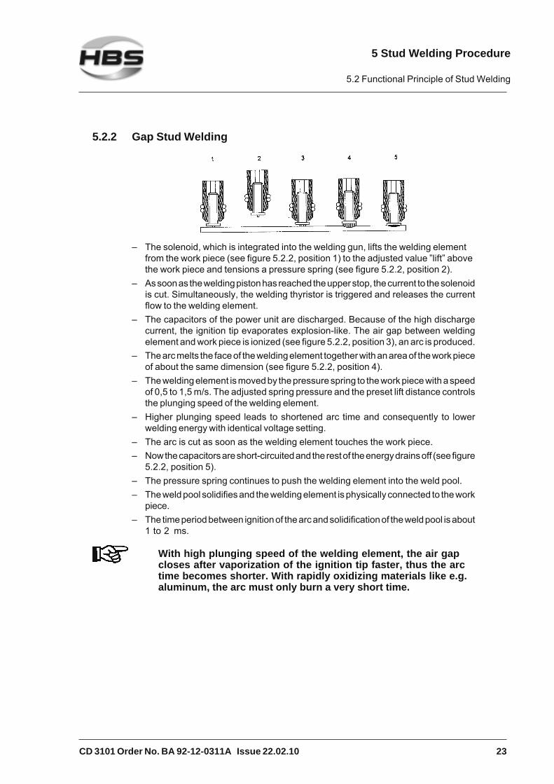
5.2.2 Gap Stud Welding
– The solenoid, which is integrated into the welding gun, lifts the welding elementfrom the work piece (see figure 5.2.2, position 1) to the adjusted value ”lift” abovethe work piece and tensions a pressure spring (see figure 5.2.2, position 2).
– As soon as the welding piston has reached the upper stop, the current to the solenoidis cut. Simultaneously, the welding thyristor is triggered and releases the currentflow to the welding element.
– The capacitors of the power unit are discharged. Because of the high dischargecurrent, the ignition tip evaporates explosion-like. The air gap between weldingelement and work piece is ionized (see figure 5.2.2, position 3), an arc is produced.
– The arc melts the face of the welding element together with an area of the work pieceof about the same dimension (see figure 5.2.2, position 4).
– The welding element is moved by the pressure spring to the work piece with a speedof 0,5 to 1,5 m/s. The adjusted spring pressure and the preset lift distance controlsthe plunging speed of the welding element.
– Higher plunging speed leads to shortened arc time and consequently to lowerwelding energy with identical voltage setting.
– The arc is cut as soon as the welding element touches the work piece.– Now the capacitors are short-circuited and the rest of the energy drains off (see figure
5.2.2, position 5).– The pressure spring continues to push the welding element into the weld pool.– The weld pool solidifies and the welding element is physically connected to the work
piece.– The time period between ignition of the arc and solidification of the weld pool is about
1 to 2 ms.
With high plunging speed of the welding element, the air gapcloses after vaporization of the ignition tip faster, thus the arctime becomes shorter. With rapidly oxidizing materials like e.g.aluminum, the arc must only burn a very short time.
5 Stud Welding Procedure
5.2 Functional Principle of Stud Welding

24 CD 3101 Order No. BA 92-12-0311A Issue 22.02.10
5.3 Welding Preparation
Read the safety instructions in chapters 1, 3 and 5.
Observe the workplace requirements (chapter 3, ”Start-up").
Check all cables and connections for proper condition.
Replace immediately defective cables and cable connections to avoid electricalshocks.
Check the chuck for proper seat (see operating manual of according weldinggun).
Before welding, make sure that the bellows are checked for damage and properseat.
5.4 High-strength Welds
The following must be removed both from the weld zone and the ground clampconnection areas:
– paint, oil and any other impurities,
– rust,
– non-conductive coatings from surface treated work pieces.
Weld to smooth and flat surfaces only.
For welding to pipes or punched plates consult our responsibleapplication manager (address of customer service see page ii).
5.5 Determination of Welding Parameters
The adjustment of welding parameters on the power unit (e.g. charging voltage via energycontroller) or on the welding gun (e.g. spring force) depends amongst others on
– material of the welding element– diameter of the welding element– material of the work piece
The guidelines should be verified by test welding on the actual material and be changedif necessary. For an assessment of welding results, see section 5.8 and 5.9.
5 Stud Welding Procedure
5.3 Welding Preparation

CD 3101 Order No. BA 92-12-0311A Issue 22.02.10 25
Data given in the following table are only guidelines. They mustbe verified by trial welds on the actual material according toactual standards and DVS guidelines (see appendix). Beforeyou use another lot of welding elements, carry out some trialwelds to verify the parameter setting.
Material of Energywelding elements CD 3101 C 08
Charging voltage Spring pressure Spring pressure LiftPT, UT IT (V) (scaling) (scaling) (mm)
S235 / St37 (4.8) M3, 3 mm -- 1/8" #6-32 50 6 2 1S235 / St37 (4.8) M4, 4 mm -- 5/32" #8-32 60 6 2 1S235 / St37 (4.8) M5, 5 mm 5 mm, M3 3/16" #10-32 80 6 2 1,6S235 / St37 (4.8) M6, 6 mm 6 mm, M4 1/4" 1/4-20 110 6 6 1,6S235 / St37 (4.8) M8, 7,1 mm 7,1 mm, M5 5/16" 5/16-18 150 9 6 2S235 / St37 (4.8) M10, -- -- 3/8" 3/8-16" 210 2) 9 6 2
S235 M3, 3 mm -- 1/8" #6-32 70 6 6 1S235 M4, 4 mm -- 5/32" #8-32 110 6 6 1S235 M5, 5 mm 5 mm, M3 3/16" #10-32 140 3 6 1S235 M6, 6 mm 6 mm, M4 1/4" 1/4-20 170 3 6 1S235 M8, 7,1 mm 7,1 mm, M5 5/16" 5/16-18 220 2) 3 -- --
1.4301, 1.4303 M3, 3 mm -- 1/8" #6-32 50 6 6 1,41.4301, 1.4303 M4, 4 mm -- 5/32" #8-32 60 6 6 1,41.4301, 1.4303 M5, 5 mm 5 mm, M3 3/16" #10-32 80 6 6 1,61.4301, 1.4303 M6, 6 mm 6 mm, M4 1/4" 1/4-20 100 6 6 21.4301, 1.4303 M8, 7,1 mm 7,1 mm, M5 5/16" 5/16-18 140 11 6 21.4301, 1.4303 M10, -- -- 3/8" 3/8-16" 200 2) 11 5 2
CuZn37 M3, 3 mm -- 1/8" #6-32 50 6 6 1CuZn37 M4, 4 mm -- 5/32" #8-32 60 6 6 1CuZn37 M5, 5 mm -- 3/16" #10-32 80 9 -- --CuZn37 M6, 6 mm -- 1/4" 1/4-20 110 9 -- --CuZn37 M8, 7,1 mm -- 5/16" 5/16-18 170 2) 9 -- --
AlMg3 M3, 3 mm -- 1/8" #6-32 50 6 9 1AlMg3 M4, 4 mm -- 5/32" #8-32 60 6 9 1,4AlMg3 M5, 5 mm 5 mm, M3 3/16" #10-32 90 6 9 2AlMg3 M6, 6 mm 6 mm, M4 1/4" 1/4-20 120 11 9 2,4AlMg3 M8, 7,1 mm 7,1 mm, M5 5/16" 5/16-18 170 2) -- 9 3
(imperial)Gun parameters
CA 08
Material of workpiece: Aluminum
(metric)
Material of workpiece: Mild steel, shiny S235 / St37.3k (4.8) weldable
Material of workpiece: Steel galvanized S235
Material of workpiece: Cr-Ni stainless steel 1.4301, 1.4303
Material of workpiece: Brass CuZn37
Diameter of welding elements
2) to be checked by trials
Further notes on– welding elements– prestress at installation (tie load) and torque– material combinationssee appendix and operating manual of the according weldinggun.
5 Stud Welding Procedure
5.5 Determination of Welding Parameters

26 CD 3101 Order No. BA 92-12-0311A Issue 22.02.10
5.6 Switching on the Power Unit
Improper operation of the stud welding unit isLIFE-THREATENING!First read the safety instructions in chapters 1. 3 and 5.
Insert the primary plug of the power unit into an appropriate socket.
Switch on the power unit with the mains switch.
The condition of the welding unit is monitored after switching-on. The display showsthree bars and the following parameters are monitored:
– Deviation from usual charging time
– Unit temperature
– Defective thyristor
– Control discharge relay
If one of the above mentioned parameters deviates from the standard value, an errormessage is displayed on the operating terminal, see section malfunctions andcorrective actions.
5 Stud Welding Procedure
5.6 Switching on the Power Unit

CD 3101 Order No. BA 92-12-0311A Issue 22.02.10 27
After self-test, the digital display shows the last set charging voltage.
There is a luminous indication (LED) below the display:
Green – on, power unit is ready for welding
Red – on, capacitor battery is charged
Red – on, power unit is locked• after welding, until there is electrical contact with the
work piece• if the power unit is overheated. After a short cooling period,
the work can continue.• if thyristor is defective• in the case of a charging malfunction (exceeding the
charging period)• if arrow keys jam• when appealing the library mode (stud diameter)
Yellow – lights if a welding gun with solenoid is connected
Yellow – lights if the welding gun button is triggered
Yellow – lights if there is electrical contact between welding elementand work piece.
5.6.1 Adjusting the Charging Voltage of Capacitors
Refer to the table in section 5.5 for the required charging voltage matching yourwelding job.
Set the charging voltage (digital display) with the arrow keys(⇑ higher – ⇓ lower) on the display.
5 Stud Welding Procedure
5.6 Switching on the Power Unit

28 CD 3101 Order No. BA 92-12-0311A Issue 22.02.10
5.6.2 Library Mode
In the library mode, you can call up and modify charging voltages, depending on studdiameter.
Simultaneously press both arrow keys (⇑ ⇓) for about one second. The displayshows 0 ... 3 (3 means the charging voltage for stud diameter M3).
You can pre-select the stud diameter (M3 to M8) with both arrow keys (⇑ higher– ⇓ lower). After about 5 seconds the display jumps onto the pre-selectedcharging voltage and the capacitor battery is charged with this value (wait untilthe power unit is ready for welding).
In addition, you can modify the charging voltage individually by pressing thearrow keys (as described above).
5.7 Welding Procedure
Improper operation of the stud welding unit isLIFE-THREATENING! The stud welding unit must only beoperated by qualified personnel (see chapter 1).Observe the safety instructions in chapters 1, 3 and 5.
Prepare the stud welding unit, the ground connection, and the work pieceaccording to the instructions given in the operating manual.
Chapter 5 contains guideline for welding parameters. The datagiven are only guidelines. They must be verified by trial weldson the actual work piece according to actual standards and DVSregulations (see appendix).
During the actual welding process, you must expect red-hot weldingspatters, possibly liquid spatters, a flash, and a loud bang may occur> 90dB (A). Inform any collegues who are occupied in the vicinity ofthe welder about the bang.Wear always your personal protective equipment according to actualstandards (see appendix).
5 Stud Welding Procedure
5.7 Welding Procedure

CD 3101 Order No. BA 92-12-0311A Issue 22.02.10 29
Insert the welding element into the chuck.
As soon as the power unit is ready for the welding process,
place the welding gun vertically against the work piece,
push the welding gun firmly with both hands onto the work piece until the weldinggun support (distance device) is evenly seated on the work piece,
hold the welding gun firmly, still, and straight,
take care that you do not touch any metallic part of the welding gun,
press the trigger button of the welding gun.
This initiates the welding process.
The welding process can only be initiated, if the current circuitis closed, i.e. the welding element is in electrical contact withthe base material.
After the welding process has been completed, withdraw thewelding gun straight back from the welding element. If youremove the welding gun at an angle, the chuck will be stret-ched, this reduces its life expectancy.
You can now insert a new welding element in the chuck and repeat the welding processas described above.
5 Stud Welding Procedure
5.7 Welding Procedure

30 CD 3101 Order No. BA 92-12-0311A Issue 22.02.10
5.8 Checking the Quality of the Weld
You can check the quality of the weld by means of a visual inspection and a bendingtest.
See also actual standards in the appendix “Arc stud welding ofmetallic materials“, in section irregularities and correctiveactions.
5.8.1 Visual Inspection
A visual inspection must be carried out with each welding element.
Condition Possible cause Corrective actionsGood welded jointLow spatters around the weld without outer flawsThe weld pool forms a collar around the flange of about 1 - 1,5 mm
- Correct parameters - None
Cold weld poolGap between flange and workpiece
- Heat input too low- Plunging speed too low- No sufficient backing of workpiece
- Increase charging voltage- Adjust plunging speed correctly- Provide sufficient backing
Hot weld poolMany spatters around the weld
- Heat input too high- Plunging speed too low
- Reduce charging voltage- Increase plunging speed
One-sided weld poolOne-sided spatter collarWeld pool came out on one side
- Arc blow effect- Unsymmetric ground connection- Welding gun put at an angle
- Take care for symmetrical ground connection- Put welding gun vertically to the workpiece
Visual Inspection
5 Stud Welding Procedure
5.8 Checking the Quality of the Weld

CD 3101 Order No. BA 92-12-0311A Issue 22.02.10 31
5.8.2 Bending Test
You can purchase from HBS a bending device with inserts for various diameters of thewelding elements.
The bending test serves as an easy work sample and as a check for the selected weldingparameters. The welded joint is stressed by bending in a non-defined way.
Bend the welding element with the bending device once by 30°.
Carry out the test in different directions.
The bending test is passed if a crack or a fracture of the welded zone does not occur.
Please note the instructions on fault recognition and corrective actions inchapter 5.
You don’t need to test all studs. It is sufficient to carry out studtests at random.
If the strength of the joint is inadequate, then:
check the setting of the stud welding unit
check whether the surface of welding element and base material are clean andelectrically conductive (must be free from scale, oil, paint, oxide layers)
grind off hardened work piece surfaces (e.g. roll hardening).
Check the piston of the welding gun for ease of movement.
5 Stud Welding Procedure
5.8 Checking the Quality of the Weld

32 CD 3101 Order No. BA 92-12-0311A Issue 22.02.10
Type of fracture Possible cause Corrective actionsBase material buckling - Correct parameters - none
Fracture in the welding elementabove flange
- Correct parameters - none
Fracture in the weld metal - Heat input too low- Plunging speed too low- Welding element/base material combination not suitable
- Increase charging voltage- Increase plunging speed- Replace welding element or workpiece
Backside deformation - Heat input too high- Pressure too high- Contact stud welding not suitable- Workpiece too thin
- Reduce charging voltage- Reduce pressure- Use gap stud welding instead of contact stud welding- Adapt thickness of workpiece
Bending Test
5 Stud Welding Procedure
5.8 Checking the Quality of the Weld
CD 3101 Order No. BA 92-12-0311A Issue 22.02.10 33
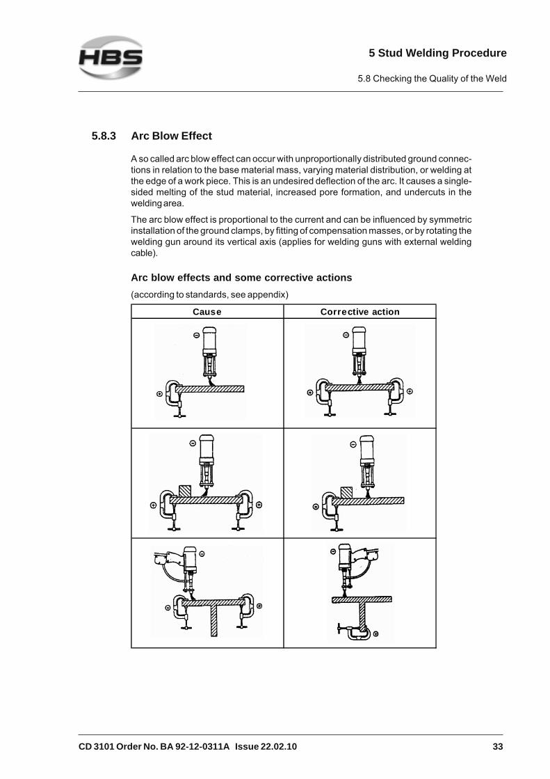
5.8.3 Arc Blow Effect
A so called arc blow effect can occur with unproportionally distributed ground connec-tions in relation to the base material mass, varying material distribution, or welding atthe edge of a work piece. This is an undesired deflection of the arc. It causes a single-sided melting of the stud material, increased pore formation, and undercuts in thewelding area.
The arc blow effect is proportional to the current and can be influenced by symmetricinstallation of the ground clamps, by fitting of compensation masses, or by rotating thewelding gun around its vertical axis (applies for welding guns with external weldingcable).
Arc blow effects and some corrective actions(according to standards, see appendix)
Cause Corrective action
5 Stud Welding Procedure
5.8 Checking the Quality of the Weld
34 CD 3101 Order No. BA 92-12-0311A Issue 22.02.10
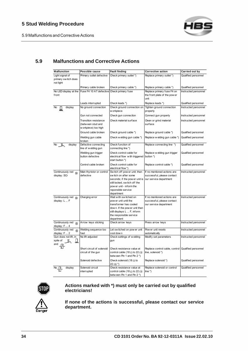
5.9 Malfunctions and Corrective Actions
Malfunction Possible cause Fault finding Corrective action Carried out byLight signal of primary sw itch does not light
Primary outlet defective Check primary outlet *) Replace primary outlet *) Qualif ied personnel
Primary cable broken Check primary cable *) Replace primary cable *) Qualif ied personnelNo LED display at the f ront
Fuse F4 10 AT defective Check primary fuse Replace primary fuse F4 on the front plate of the pow er unit
Instructed personnel
Leads interrupted Check leads *) Replace leads *) Qualif ied personnelNo display No ground connection Check ground connection on
w orkpieceTighten ground connection properly
Instructed personnel
Gun not connected Check gun connection Connect gun properly Instructed personnel
Transition resistance (betw een stud and w orkpiece) too high
Check material surface Clean or grind material surface
Instructed personnel
Ground cable broken Check ground cable *) Replace ground cable *) Qualif ied personnel
Welding gun cable broken
Check w elding gun cable *) Replace w elding gun cable *) Qualif ied personnel
No display Defective connecting line of w elding gun
Check function of connecting line *)
Replace connecting line *) Qualif ied personnel
Welding gun trigger button defective
Check control cable for electrical f low w ith triggered start button *)
Replace w elding gun trigger button *)
Qualif ied personnel
Control cable broken Check control cable for electrical f low *)
Replace control cable *) Qualif ied personnel
Continuously red display: SCr
Main thyristor or control defective
Sw itch off pow er unit; then sw itch on af ter some seconds; if the pow er unit is still locked, sw itch off the pow er unit - inform the reponsible service department
If no mentioned actions are successful, please contact our service department
Instructed personnel
Continuously red display: L ... F
Charging error Wait w ith sw itched on pow er unit until the transformer has cooled dow n. If the pow er unit then still displays L ... F, inform the responsible service department
If no mentioned actions are successful, please contact our service department
Instructed personnel
Continuously red display: F ... 4
Arrow keys sticking Check arrow keys Press arrow keys Instructed personnel
Continuously red display: F ... 2
Welding sequence too fast
Let sw itched on pow er unit cool dow n
Pow er unit resets automatically
Instructed personnel
Gun does not lift, in spite of , and
No lif t adjusted Check settings of w elding gun
Modify set parameters Instructed personnel
Short circuit of solenoid circuit of the gun
Check resistance value at control cable (18 to 22 ) betw een Pin 1 and Pin 2 *)
Replace control cable, control line, solenoid *)
Qualif ied personnel
Solenoid defective Check solenoid (18 to 22 ) *)
Replace solenoid *) Qualif ied personnel
No display Solenoid circuit interrupted
Check resistance value at control cable (18 Ω to 22 ) betw een Pin 1 and Pin 2 *)
Replace solenoid or control line *)
Qualif ied personnel
Actions marked with *) must only be carried out by qualifiedelectricians!
If none of the actions is successful, please contact our servicedepartment.
5 Stud Welding Procedure
5.9 Malfunctions and Corrective Actions

CD 3101 Order No. BA 92-12-0311A Issue 22.02.10 35
5.10 Welding Elements
The stud welding unit must be suitable for welding the welding elements to be used.Observe the instructions in the operating manuals.
Welding elements manufactured with the cold formed process have a flange and anignition tip (see actual standards in the appendix). During welding, the flange preventsthe arc getting to the cylindric part of the welding element and increases simultaneouslythe welding area.
We recommend the following standard welding elements (see appendix).
Use only welding elements of the same lot. Take particular carenot to mix-up different lots. Slightest variations in geometry ofthe welding elements, especially of the ignition tip, requiremodified settings of the welding process.
Threaded stud PT * Diameter Length Chuck
M3 6-30 mm 82-50-003M4 6-40 mm 82-50-004M5 8-45 mm 82-50-005M6 8-55 mm 82-50-006M8 10-55 mm 82-50-008
Materials: Mild steel S235 / St37.3k (4.8) / Stainless steel 1.4301, 1.4303 /Brass CuZn37 / Aluminum AlMg3
Pin UT * Diameter Length Chuck
3 mm 6-25 mm 82-50-0034 mm 6-25 mm 82-50-0045 mm 6-40 mm 82-50-0056 mm 8-50 mm 82-50-0067.1 mm 10-55 mm 82-50-071
Materials: Mild steel S235 / St37.3k (4.8) / Stainless steel 1.4301, 1.4303 /Brass CuZn37 / Aluminum AlMg3
Pin with internal thread IT * Diameter Length Chuck Internal thread(internal thread insert)
5 mm 6-30 mm 82-50-905 M36 mm 8-30 mm 82-50-906 M36 mm 8-30 mm 82-50-906 M47.1 mm 10-30 mm 82-50-971 M58 mm 10-40 mm 82-50-908 M6
Materials: Mild steel S235 / St37.3k (4.8) / Stainless steel 1.4301, 1.4303 /Brass CuZn37 / Aluminum AlMg3
* above 40 mm length, only weldable with distance ring up to 55 mm,order no. 92-40-010.
5 Stud Welding Procedure
5.10 Welding Elements

36 CD 3101 Order No. BA 92-12-0311A Issue 22.02.10
Tapped pad Dimensions Chuck
6.3 82-50-050
Materials: Mild steel S235 / St37.3k (4,8) / Stainless steel 1.4301, 1.4303 /Brass CuZn37 / Aluminum AlMg3
ISO-nails ** Diameter Length Chuck
2 20-100 mm 82-50-0203 30-250 mm 82-50-030
Materials: Mild steel S235 / St37.3k (4,8) / Stainless steel 1.4301, 1.4303
ISO-clip for nails
Ø 2
Ø 3
Materials: Mild steel St2k70 galvanized / Stainless steel 1.4301, 1.4303
ISO-clip for nailsplastic coated
Ø 3
Material: Mild steel St2k70 galvanized
We look forward to consult you with view to special welding elements and other specialmaterials.
HBS Bolzenschweiss-Systeme GmbH & Co. KGFelix-Wankel-Strasse 1885221 Dachau / GermanyPhone +49 (0) 8131 511-0Fax +49 (0) 8131 511-100E-mail [email protected]
** above 100 mm length, only weldable with tripod order no. 92-40-043.
5 Stud Welding Procedure
5.10 Welding Elements

CD 3101 Order No. BA 92-12-0311A Issue 22.02.10 37
6 Switching off the Power Unit
This chapter describes what you should observe when you switch off the power unittemporarily or completely.
6.1 Temporary Switching off
Switch off the power unit.
Unplug the control cable and the welding cable from the power unit.
Protect the power unit against ingress of fluids and foreign bodies.
6.2 Disposal
If you shut down the installation, you can return the complete power unit to HBS (foraddress see page ii).
We will take care of environmentally correct material separation and disposal.
6 Switching off the Power Unit
6.1 Temporary Switching off

38 CD 3101 Order No. BA 92-12-0311A Issue 22.02.10
7 Care and Maintenance
7.1 Safety Instructions
Let maintenance and repair operations be carried out only byqualified personnel or by your competent service technician.Before starting any repair or maintenance operation, always switchthe power unit off and disconnect the primary plug.Do not wear a wrist watch or any electrically conductive jewellery.
7.2 Regular Maintenance Operations
Clean the inner components of the power unit periodically ofdust. Use a dry washcloth or a brush. To open the power unit,proceed as described in section 7.1, 7.3 and 7.4.
Clean the surface of the power unit with a humid washcloth and a detergent.
Do not use any solvent containing cleaning agents. Solventcontaining cleaning agents may damage the surface of thepower unit.
After a longer break of the power unit (longer than 4 weeks), werecommend to charge the welding capacitors slowly, i.e. set thecharging voltage to 50 V for 5 minutes, then to 75 V, 100 V,125 V... for 5 minutes each.
7.3 Tools to be Used
– Cross-slotted screwdriver, size 2
7 Care and Maintenance
7.1 Safety Instructions

CD 3101 Order No. BA 92-12-0311A Issue 22.02.10 39
7.4 Open the Power Unit
Open the power unit only if you are sufficiently qualified inrepairing electrical equipment.
Remove the 12 screws of the casing (6 at each side).
Carefully remove the cover and disconnect the ground cable on the inside of thecover.
Now pull off the cover.
7 Care and Maintenance
7.4 Open the Power Unit

40 CD 3101 Order No. BA 92-12-0311A Issue 22.02.10
THREAT TO LIFE!Check whether the welding capacitors are discharged.
Measure the voltage with a standard voltmeter (measurement range DC/–). Thevoltage display must be below 10 V.
Re-assemble the power unit in reverse sequence.
Make sure that no cables are jammed or sheared duringassembly.
7 Care and Maintenance
7.4 Open the Power Unit

CD 3101 Order No. BA 92-12-0311A Issue 22.02.10 41
8 Appendix
In the appendix, there is information of interest regarding technical data, spare part lists,accessories, standards, etc.
8.1 Technical Data
Power Unit CD 3101 (with digital display)for CD stud welding (capacitor discharge welding) according to currentstandards
Welding range #8 to 7/16", dia. #8 to 3/8"(M4 to M10, dia. 4 to 10 mm)
Welding material Mild steel, stainless steel, aluminum andbrass
Welding rate 5 to 20 studs/min(depending on application and stud dia.)
Capacitance 132,000 μF
Welding time 1 to 3 msec
Energy 3,200 Ws
Charging voltage 50 to 220 V (stepless voltage regulation)
Primary power 115/230 V, 50/60 Hz, 10 AT
Power source Capacitor
Cooling type F (temperatur controlled cooling fan)
Protection class IP 21 (not allowed to use while raining)
Operational and storage conditions According to current standards
Dimensions L x W x H 20.08" x 7.09" x 9.84" (510 x 180 x 250 mm)without handle
Weight 48.50 lbs (22 kg )
8 Appendix
8.1 Technical Data

42 CD 3101 Order No. BA 92-12-0311A Issue 22.02.10
8.2 Spare Parts
Spare part list power unit type CD 3101 (92-12-0311A)When ordering spare parts, please indicate order number and type of power unit.
Pos. Quantity Order-No. Description
5 1 88-11-890 Bottom plate8 4 80-90-178 Screw M4 x 129 4 80-90-164 Washer 4 mm10 4 80-10-203 Casing feet13 3 80-11-359 Conductor mark ground cable
20 1 80-30-369A Capacitor battery21 4 80-90-128 Spring washer 5 mm22 4 80-90-250 Screw M5 x 825 1 88-11-785A Rear wall complete26 16 80-90-158 Screw M4 x 6 black
27 4 80-90-184 Tooth lock washer A430 1 80-50-565 Mains cable35 1 88-11-781B Front plate36 1 80-90-253 Screw M8 x 2537 2 80-90-150 Washer 8 mm
38 2 80-90-167 Cupal washer M 839 1 80-90-140 Spring washer 8 mm40 1 80-90-141 Nut M842 1 80-70-296 Connection cable43 1 80-70-293 Connection cable
50 1 88-11-891 Cover51 1 80-11-851 Label matt black55 1 80-10-857 Handle A=30056 2 80-90-199 Screw M5 x 1257 2 80-90-185 Washer 5 mm
58 2 80-90-225 Head nut M565 1 80-11-852 Label matt white70 1 80-11-754 HBS-Logo small, 37 x 28
1 80-70-294 Harness
8 Appendix
8.2 Spare Parts

CD 3101 Order No. BA 92-12-0311A Issue 22.02.10 43
Power unit, type CD 3101 (92-12-0311A)
8 Appendix
8.2 Spare Parts

44 CD 3101 Order No. BA 92-12-0311A Issue 22.02.10
Spare part list capacitor battery CD 3101 (80-30-369A), Part 1
Pos. Quantity Order-No. Description
1 1 80-10-052 Clamping device - II4 1 80-40-311 Cupal plate7 1 80-09-082 Conductor rail12 5 80-11-116 Grommets support14 1 80-09-080F Capacitor support
15 3 80-04-983A Spacer17 1 80-55-059 Diode20 1 80-55-012 Thyristor23 3 80-10-851 Edge protection24 4 80-56-133 Capacitor
30 1 80-50-097 Temperature controller42 1 80-09-081 Transformer support43 1 80-81-324 Toroidal core transformer45 1 80-10-249 Flat connection50 1 80-08-793 Resistor support
55 2 80-57-037 Resistor 30 R, 70 W60 1 80-57-010 Resistor 10 R, 70 W64 1 80-40-066B Distance stud65 1 80-56-041 Capacitor70 1 80-57-332 Resistor L
71 2 80-90-202 Washer 5 mm72 2 80-90-177 Tooth lock washer A573 2 80-90-127 Screw M5 x 875 1 80-10-785 Adhesive clip110 4 80-90-150 Washer 8 mm
130 1 80-90-121 Spring washer 4 mm140 3 80-90-147 Spring washer 6 mm145 3 80-90-140 Spring washer 8 mm165 2 80-90-141 Nut M8175 1 80-90-110 Screw M4 x 8
180 4 80-90-134 Screw M6 x 35185 3 80-90-342 Screw M6 x 8190 6 80-10-1201 Screw EJOT 6,0 x 18195 1 80-10-1202 Screw EJOT 6,0 x 12200 1 80-90-248 Screw M8 x 25
8 Appendix
8.2 Spare Parts

CD 3101 Order No. BA 92-12-0311A Issue 22.02.10 45
210 2 80-90-149 Screw M8 x 20215 5 80-90-246 Screw 3,9 x 16
8 Appendix
8.2 Spare Parts

46 CD 3101 Order No. BA 92-12-0311A Issue 22.02.10
Spare part list capacitor battery CD 3101 (80-30-369A), Part 2
Pos. Quantity Order-No. Description
5 1 80-40-199 Clamping plate11 2 80-11-360 Warning sign 2,5 SL27 2 80-11-121 Flat connection100 8 80-90-198 Washer 6 mm110 4 80-90-150 Washer 8 mm
115 1 80-90-274 Washer 17 mm120 8 80-90-239 Cupal washer M6123 2 80-90-167 Cupal washer M8140 3 80-90-147 Spring washer 6 mm145 3 80-90-140 Spring washer 8 mm
150 1 80-90-243 Spring washer M 16155 1 80-90-272 Nut M 16165 2 80-90-141 Nut M 8205 8 80-90-151 Screw M6 x 16210 2 80-90-149 Screw M8 x 20
215 5 80-90-246 Screw 3,9 x 16225 8 80-90-245 Locking washer 6 mm
8 Appendix
8.2 Spare Parts

CD 3101 Order No. BA 92-12-0311A Issue 22.02.10 47
Capacitor battery CD 3101 (80-30-369A), Part 2
8 Appendix
8.2 Spare Parts
48 CD 3101 Order No. BA 92-12-0311A Issue 22.02.10
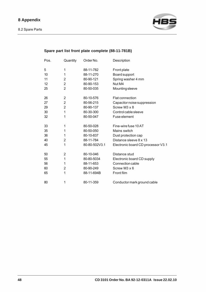
Spare part list front plate complete (88-11-781B)
Pos. Quantity Order No. Description
5 1 88-11-782 Front plate10 1 88-11-270 Board support11 2 80-90-121 Spring washer 4 mm12 2 80-90-153 Nut M425 2 80-50-035 Mounting sleeve
26 2 80-10-576 Flat connection27 2 80-56-215 Capacitor noise suppression29 2 80-90-137 Screw M3 x 830 1 80-30-300 Control cable sleeve32 1 80-50-047 Fuse element
33 1 80-50-028 Fine-wire fuse 10 AT35 1 80-50-050 Mains switch36 1 80-10-837 Dust protection cap40 2 88-11-784 Distance sleeve 8 x 1345 1 80-80-502V3.1 Electronic board CD processor V3.1
50 2 80-10-046 Distance stud55 1 80-80-5034 Electronic board CD supply56 1 88-11-653 Connection cable60 2 80-90-249 Screw M3 x 665 1 88-11-694B Front film
80 1 80-11-359 Conductor mark ground cable
8 Appendix
8.2 Spare Parts

CD 3101 Order No. BA 92-12-0311A Issue 22.02.10 49
Front plate complete (88-11-781B)
8 Appendix
8.2 Spare Parts

50 CD 3101 Order No. BA 92-12-0311A Issue 22.02.10
Spare part list rear wall complete (88-11-785A)
Pos. Quantity Order No. Description
5 1 88-17-995 Rear wall10 1 80-50-049 Fan13 4 80-90-252 Blind rivet 4 x 1614 1 80-90-184 Tooth lock washer A415 1 80-11-440 Screwed cable connection
20 1 80-11-441 Lock nut24 2 80-90-194 Tooth lock washer A325 1 80-50-775 Mains anti interference filter27 2 80-90-131 Washer 3 mm28 2 80-90-190 Spring washer 3 mm
29 2 80-90-165 Nut M331 1 80-11-356 Conductor mark L1-outside wire32 1 80-11-357 Conductor mark N-neutral cable33 1 80-11-358 Conductor mark PE-ground cable34 1 80-11-359 Conductor mark ground cable
37 1 80-90-177 Tooth lock washer A538 2 80-90-188 Nut M539 2 80-90-202 Washer 5 mm41 1 80-90-128 Spring washer 5 mm
8 Appendix
8.2 Spare Parts

CD 3101 Order No. BA 92-12-0311A Issue 22.02.10 51
Rear wall complete (88-11-785A)
8 Appendix
8.2 Spare Parts

52 CD 3101 Order No. BA 92-12-0311A Issue 22.02.10
Changing the electronic board
Changing the electronic board may only be carried out bysufficiently qualified personnel or by your service technician.Before starting any repair or maintenance operation, always switchthe power unit off and disconnect the primary plug.Do not wear a wrist watch or any electrically conductive jewellery.
To change the electronic board, proceed as described insection 7.1 (Safety Instructions), 7.3 (Tools to be Used) and 7.4(Open the Power Unit).
Replacement of the electronic board 80-80-5034Loosen the plugs X1, X2, X3, and SV2.
8 Appendix
8.2 Spare Parts

CD 3101 Order No. BA 92-12-0311A Issue 22.02.10 53
Remove the two screws.
Replace the electronic board. For re-assembly, proceed in reversed sequence.
Replace the electronic board 80-80-502V3.1See changing the electronic board 80-80-5034. In addition, you must remove thetwo spacers.
Replacement of the electronic board 80-80-502V3.1.
8 Appendix
8.2 Spare Parts

54 CD 3101 Order No. BA 92-12-0311A Issue 22.02.10
Switch on the power unit and choose the correct type by using arrows (⇑ ⇓ ).
Range display:
suits to CD 1501
suits to CD 2301
suits to CD 3101
suits to special type
suits to special type
suits to CD 1504
suits to special type
suits to special type
suits to special type
suits to SC 2401
suits to special type
suits to special type
Switch off the power unit and disconnect the primary plug.
Loosen the jumper for library mode table with tweezers or a grip.
P.C. board 80-80-502V3.1 is now adjusted for the correct type.
8 Appendix
8.2 Spare Parts

CD 3101 Order No. BA 92-12-0311A Issue 22.02.10 55
Switching the primary voltage
Attention: Compare the primary voltage specified on the typeplate with the voltage provided by your primary power supply.The type plate is located on the backside of the power unit.
Primary voltage switch 230 V to 115 V:
Switch off power unit!
Attention: Observe jumper position!!
With wrong primary voltage setting, the power unit may bedamaged.
Switching the primary voltage may only be carried out bysufficiently qualified personnel or by your service technician.Before starting any repair or maintenance operation, always switchthe power unit off and disconnect the primary plug.Do not wear a wrist watch or any electrically conductive jewellery.
To switch the primary voltage, proceed as described in section7.1 (Safety Instructions), 7.3 (Tools to be Used) and 7.4 (Openthe Power Unit).
8 Appendix
8.2 Spare Parts
56 CD 3101 Order No. BA 92-12-0311A Issue 22.02.10
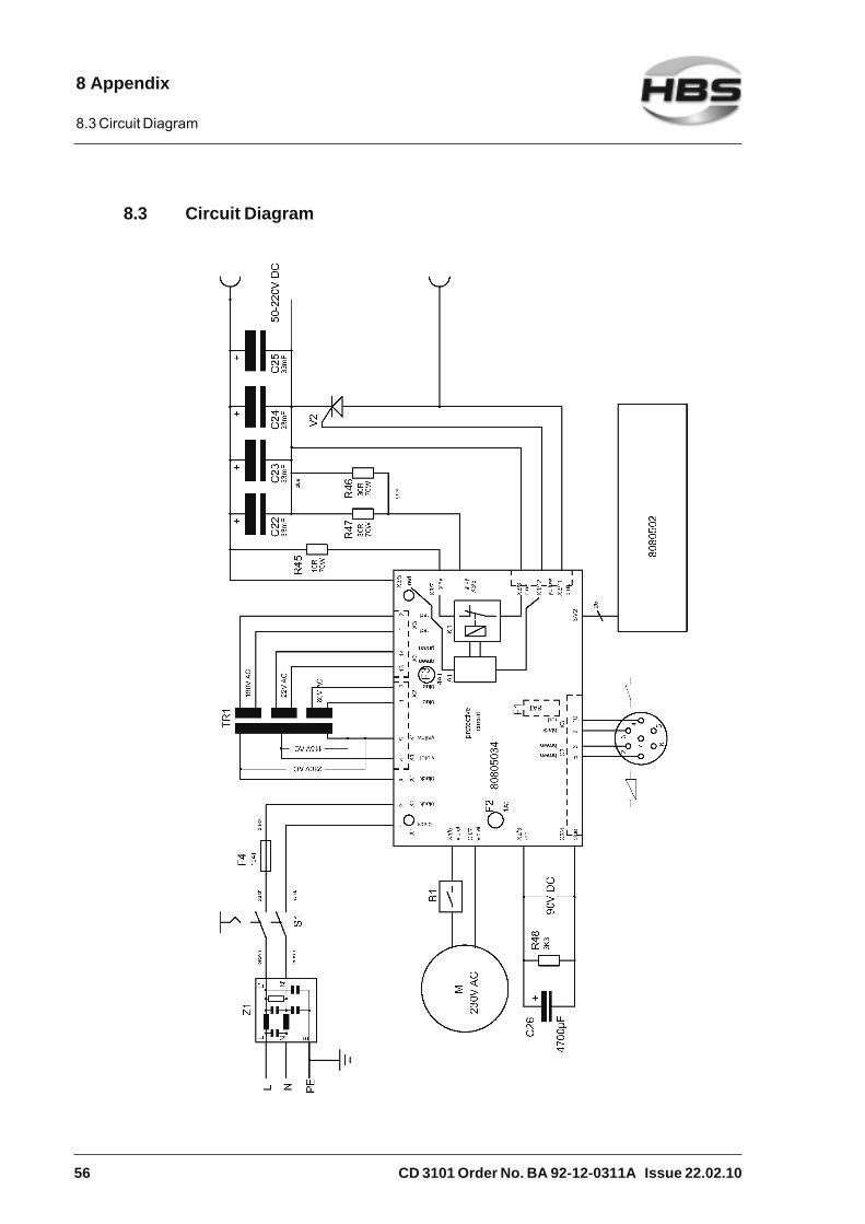
8.3 Circuit Diagram
8 Appendix
8.3 Circuit Diagram
CD 3101 Order No. BA 92-12-0311A Issue 22.02.10 57
8.4 Environmentally Admissible Disposal
After repair of the power unit, dispose replaced parts in an environmentallyadmissible way.
Used materials: - Steel
- Nonferrous metals (brass, copper)
- Plastics
- Aluminum
8 Appendix
8.4 Environmentally Admissible Disposal

58 CD 3101 Order No. BA 92-12-0311A Issue 22.02.10
Glossary
Arc: Electrical discharge at its own between two electrodesunder sufficiently high current. Whitish light is emitted.The arc generates very high temperatures.
Automatic welding head: Device to weld welding elements
Capacitor: A component which serves as storage of electrical charge
Power unit: Device to provide electrical energy for stud welding
Rectifier: Electric component transforming alternating current intodirect current
Stud feeder: Device for the automatic stud feeding of welding elements
Stud welding unit: Power unit inclusive welding gun
Thyristor: Electronic component, contactless switch, which will letthe current only pass through if a control pulse is given tothe gate (additional electrode)
Welding element: A component, like a stud, bolt, pin, which is welded to thework piece
Welding gun: Device to weld welding elements
Welding parameters: Various settings on the gun as well as on the power unit.For example: duration and strength of current duringwelding process, charging voltage, spring force of thewelding gun.
Work piece: A component, like a sheet, tube, etc. to which the weldingelement is fastened
Glossary

CD 3101 Order No. BA 92-12-0311A Issue 22.02.10 59
Regulations and Standards
The regulations and standards are recommendations and don`t purport to becompletely.
Standards, regulations Description
Stud welding (fundamentals)
DIN EN ISO 13918 Welding - Studs and ceramic ferrules for arcstud welding
DIN EN ISO 14555 Welding - Arc stud welding of metallic materials
DIN EN 1418 Welding personnel - Approval testing of weldingoperators for fusion welding and resistance weldsetters for fully mechanized and automaticwelding of metallic materials
DVS 0901 Stud welding method for metals - General
DVS 0902 Drawn-arc stud welding
DVS 0903 Capacitor-discharge stud welding with tipignition
DVS 0904 Instructions for practice - Arc stud welding
DVS 2927 Resistor projection welding and Arc welding ofone-sided thick plastics coated thin metalsheets
Stud welding (general)
DIN EN ISO 4063 Welding and allied processes - Nomenclature ofprocesses and reference numbers
DIN ISO 857-1 Welding and allied processes - Vocabulary -Part 1: Metal welding processes
DIN EN ISO 14175 Welding consumables - Gases and gasmixtures for fusion welding and allied processes
DIN EN 764-1 Pressure equipment - Part 1: Terminology -Pressure, temperature, volume, nominal size
DIN EN ISO 6947 Welds - Working positions - Definitions ofangles of slope and rotation
Regulations and Standards

60 CD 3101 Order No. BA 92-12-0311A Issue 22.02.10
Machine safety
2006/95/EC Electrical equipment designed for use withincertain voltage limits
2004/108/EC EMC-Guidelines
2006/42/EC Machine guideline
DIN EN 60204-1 Safety of machinery - Electrical equipment ofmachines - Part 1: General requirements
DIN EN 60529 Degrees of protection provided by enclosures(IP code)
DIN EN 60974-1 Arc welding equipment - Part 1: Welding powersources
DIN EN 60974-10 Arc welding equipment - Part 10:Electromagnetic compatiblity (EMC)requirements
Personal safety and accident prevention
DIN EN ISO 20345 Personal protective equipment -Safety footwear
DIN EN 12477 Protective gloves for welders
DIN EN 166 Personal eye-protection - Specifications
DIN EN 352-1 Hearing protectors - General requirements -Part 1: Ear-Muffs
BGV A1 Accident-prevention regulation „Principles ofprevention“
BGV A3 Accident-prevention regulation „Electricalequipment and operating material“
BGV A8 Accident-prevention regulation „Health andsafety signs at work“
BGV B11 Safety rules “EMC”
BGV D1 Safety rules - welding, cutting and similarprocesses
Please note that in your country additional standards and safetyconditions (especially rules for accident prevention) may differfrom the standards mentioned in this operating manual.
Regulations and Standards

CD 3101 Order No. BA 92-12-0311A Issue 22.02.10 61
Further Instructions
Welding elements, abbreviations, materials, standards, mechanicalproperties to actual standards
Abbreviationsfor studs Material
Materialinternational
nameNorm
Mechanicalcharacteristics
Steel (S235) 4.81)
copper platedMild steel ISO 898-1 See ISO 898-1
Stainless steelAISI 304/305
Brass
EN AW-Al99,5
Aluminum99,5
EN 573-3 Rm ≥ 100 N/mm2
AluminumAlMg3
EN AW-AlMg3
EN 12301-2 Rm ≥ 230 N/mm2
1.4301/03(A2-50)
ISO 3506-1 ISO 3506-1
CuZn37(Ms63)
EN 12166 Rm ≥ 370 N/mm2
ITStud w ith internal
thread
Stud types
Threaded stud PT
Pin(Unthreaded stud)
UTStud w elding w ithcapacitor
discharge (TS)
Further materials on request 1) weldable
Prestress at installation (tie load) and torque
Threadedstud
Prestress at installation
(kN)
Torque(Nm)
Prestress at installation
(kN)
Torque(Nm)
Prestress at installation
(kN)
Torque(Nm)
Prestress at installation
(kN)
Torque(Nm)
M 3 1,1 0,8 0,7 0,5 0,5 0,4 0,8 0,6M 4 1,8 1,8 1,1 1,1 1,0 0,9 1,4 1,3M 5 3,0 3,6 1,9 2,3 1,6 1,9 2,3 2,7M 6 4,3 6,1 2,7 3,8 2,2 3,1 3,2 4,5M 8 8,0 15,0 4,9 9,5 4,0 7,5 6,0 11,0
M 10 13,0 30,0 7,8 19,0
Steel (S235) 4.81)
µ = 0,18Rp0,2 = 340 N/mm2
1.4301/03 (A2-50)µ = 0,18
Rp0,2 = 210 N/mm2
AlMg3 (F23)µ = 0,18
Rp0,2 = 170 N/mm2
CuZn37 (Ms63)µ = 0,18
Rp0,2 = 250 N/mm2
Values correspond with actual standards 1) weldableAll given values are leads for minimum tensile strength and minimum torque of a weld without permanent deformationof parts to be joined. Parts to be joined must have sufficient wall thickness. Values apply for cold rolled threaded studswith standard thread without surface protection and without thread lubrication. Throughout the entire stud length, atleast the stressed cross section must be present. Values apply for indicated yield strengths.
Material combinationsaccording to DIN EN ISO 14555 (Select stud material in a way that material of thesame kind is welded)
ISO/TR 15608Groups 1 - 6, 11.1
ISO/TR 15608 Groups 1 - 6, 11.1 and galvanized and metal plated steel sheets, max. coating thickness
25 µm
ISO/TR 15608
Group 8
Copper and unleaded
copper alloys,e.g. CuZn37 (CW508L)
ISO/TR 15608
Groups 21 and 22
Steel (S235) 4.81) a b a b --
1.4301/1.4303 a b a b --
CuZn37 b b b a --
EN AW-Al99,5 -- -- -- -- b
EN AW-AlMg3 -- -- -- -- a
-- non weldablea well suited fo r any application, e.g. power transmissionb suitable, limitations with power transmission
Base material
Stud material
Exemplification of welding suitability:
Weldability tests of other material combinations upon request. 1) weldable
Further Instructions

62 CD 3101 Order No. BA 92-12-0311A Issue 22.02.10
Guarantee Clauses
Please refer to the current “General Terms and Conditions” for the guarantee clauses.
We are not liable for malfunctions which are caused by
– normal wear,
– improper use,
– non-observing the operating manual,
– transport damages.
Any guarantee claim will be cancelled if repair operations are carried out by unauthorizedpersons.
Warning: Unauthorized interference with the stud welding unitas well as unauthorized alteration of the stud welding unit areprohibited and result in complete cancellation of any guaranteeand liability claims against HBS.
Please fill in the serial number:
Serial number automatic welding head: ..............................................
Serial number power unit: ..............................................
Serial number stud feeder: ..............................................
Serial number welding gun: ..............................................
Please indicate the serial numbers in case of enquiries or when ordering spare parts.
Guarantee Clauses

CD 3101 Order No. BA 92-12-0311A Issue 22.02.10 63
Confirmation
Herewith I confirm that I have read and understand the present operating manualcompletely.
Date Name
________________ ___________________________________
________________ ___________________________________
________________ ___________________________________
________________ ___________________________________
________________ ___________________________________
________________ ___________________________________
________________ ___________________________________
________________ ___________________________________
________________ ___________________________________
________________ ___________________________________
________________ ___________________________________
________________ ___________________________________
________________ ___________________________________
________________ ___________________________________
________________ ___________________________________
________________ ___________________________________
________________ ___________________________________
Confirmation

64 CD 3101 Order No. BA 92-12-0311A Issue 22.02.10
Feedback
HBS Bolzenschweiss-Systeme Sender:
GmbH & Co. KG __________________________
Felix-Wankel-Strasse 18 __________________________
85221 Dachau / Germany __________________________
Postfach 13 46 __________________________
85203 Dachau / Germany __________________________
Product description __________________________
Serial number __________________________
My opinion/criticism/complaints/indication of malfunction:
Date and signature ___________________________________________
Feedback

CD 3101 Order No. BA 92-12-0311A Issue 22.02.10 65
Service & Support
Service & Support

66 CD 3101 Order No. BA 92-12-0311A Issue 22.02.10
Index
Aaccident prevention ........................... 10, 20accident prevention regulations ............... 14accidents ................................................ 21accompanying documents .......................11airborne particles ..................................... 14arc .........................................22, 23, 35, 58arc blow effect ......................................... 33arrow keys .............................................. 27articles, combustible ............................... 14automatic welding head ........................... 58
Bbang ............................................ 15, 21, 28bending device with inserts ...................... 31bending test ............................................ 31blow-up ................................................... 20
Ccables, defective ..................................... 24capacitor ................................................. 58capacitor battery ..................................... 18capacitors ......................................... 22, 23care ........................................................ 38care and maintenance ............................... 8charging resistor ..................................... 18charging voltage ................................ 24, 27company specific
maintenance instruction ..................... 7company specific work order ..................... 7components of the power unit .................. 18confirmation ............................................ 63confirmation, operator sign ........................ 7contact .................................................... 18contact welding ....................................... 22control cable connector ........................... 16cooling fan ............................................... 41corrective actions .................................... 31cover ....................................................... 39cross-slotted screwdriver ......................... 38
Ddelivery ................................................ 8, 13display .................................................... 18disposal .................................................. 37disposal, environmentally admissible ....... 57distance device ....................................... 29
DVS regulations ...................................... 28
Eear protection ...................................... 7, 20electrical shock, risk of ........................... 16electrical voltage ................................. 9, 12electromagnetic fields ............................... 9electronic board, replacement of the ........ 52energy controller ..................................... 24entire plug connection, destroying ........... 16
Ffault recognition ....................................... 31feedback ................................................. 64fire extinguisher ................................. 14, 20fire risk .................................................... 20flange ...................................................... 35flash ............................................ 15, 21, 28fluids, ingress of ...................................... 37foreign bodies, ingress of ......................... 37fume extraction ....................................... 20function ................................................... 18functional principle .................................... 8further instructions .................................. 61fuse rating ............................................... 15
Ggap stud welding ..................................... 23general ...................................................... 7general safety instructions ...................... 10glossary .................................................. 58gloves ....................................................... 7ground cable ........................................... 17ground clamps ........................................ 17ground connection ............................. 17, 39guarantee claims ......................... 10, 21, 62guarantee clauses ................................... 62guide ......................................................... 8
Hheadgear, protective ................................ 20heat built-up ............................................ 14hollow parts, welding on .......................... 20
Iignition tip ................................... 22, 23, 35intended use ........................................... 10internal thread insert ................................ 35
Index

CD 3101 Order No. BA 92-12-0311A Issue 22.02.10 67
ISO-clip ................................................... 36ISO-clip plastic coated ............................ 36ISO-nail ................................................... 36IT, pin with internal thread ............ 25, 35, 61
Kkey.......................................................... 18keyboard ................................................. 18
Lliability, any ................................. 10, 21, 62library mode ............................................ 28library mode (stud diameter) .................... 18lift (see manual welding gun,
welding head) ................................... 23liquid spatters ......................................... 28liquids, combustible ................................ 14locked ..................................................... 18lot ........................................................... 35
Mmagnetic fields .................................. 14, 21mains switch ........................................... 26maintenance ....................................... 7, 38maintenance instruction ............................ 7maintenance instruction
for your company ............................... 7malfunction ............................................... 7markings ................................................. 12material combinations ....................... 25, 61material of the welding element ............... 24material of the work piece ....................... 24material separation,
environmentally correct .................... 37materials, rapidly oxidizing ...................... 22metal spatters ......................................... 20
Nnon-combustible clothes ......................... 20
Ooperating manual ................................. 7, 13operating manual, storage of ..................... 7operation, improper ................................. 28operators ................................................... 7order number ........................................... 42ordering spare parts ................................ 62
Ppace maker ................................... 9, 15, 21personal injury ........................................... 9personnel, properly instructed, qualified ..... 7personnel, qualified ................................... 7pin UT ..................................................... 35pin with internal thread IT ......................... 35pipes, welding to ..................................... 24place of operation .................................... 10plunging speed .................................. 22, 23power unit ............................................... 58power unit, switching on .......................... 26prestress at installation ..................... 25, 61primary power supply .............................. 15primary voltage, switching the ................. 55production ................................................. 7protective apron ....................................... 20protective equipment ......................... 15, 21protective equipment, personal .................. 7protective gloves ...................................... 20protective goggles ..................................... 7PT, threaded stud ........................ 25, 35, 61punched plates ........................................ 24punched plates, welding to ...................... 24
Rready for welding ..................................... 18rectifier .............................................. 18, 58recycling ................................................. 57regulations .............................................. 59repair ....................................................... 57requirements of workplace ....................... 14risk of material damage ............................. 9room adequately ventilated ................ 14, 20rooms exposed to risk of explosion ......... 14
Ssafety goggles with a window providing
protection ......................................... 20safety instructions ......................... 7, 19, 38safety symbols .......................................... 9serial number .......................................... 62service ...................................................... 7service & support .................................... 65service technician ...................................... 7set-up ....................................................... 7shoes ........................................................ 7
Index

68 CD 3101 Order No. BA 92-12-0311A Issue 22.02.10
welding elements ........................ 10, 25, 35welding elements, lot of ........................... 25welding energy .................................. 22, 23welding gun ....................................... 10, 58welding gun cables .................................. 16welding gun support (distance device) ..... 29welding parameters ........................... 28, 58welding parameters, determination of ...... 24welding preparation ................................. 24welding procedure ................................... 28welding process ........................................ 8welding spatters ...................................... 28welding thyristor ...................................... 18welds, high-strength ................................ 24work piece............................................... 58working place, change of ......................... 17
solenoid .................................................. 18spare part list .......................................... 42spare parts .............................................. 42spare parts, ordering of ...................... 42, 62special welding elements ........................ 36spring force (see manual welding gun,
welding head) ................................... 24stand-by display ...................................... 18standards ................................................ 59standards, actual .............................. 10, 28starting-up ........................................... 8, 14stud feeder .............................................. 58stud welding, functional principle ............. 22stud welding procedure............................ 19stud welding process ................................ 8stud welding unit ..................................... 58surface of welding element ...................... 31surface, workpiece .................................. 31switching off, temporary .......................... 37switching off the power unit ................. 8, 37
Ttechnical data ..................................... 8, 41threaded stud PT ..................................... 35threat to life ............................................... 8thyristor ............................................. 27, 58tools ........................................................ 38torque ............................................... 25, 61training according to current standards ...... 7transformer .............................................. 18transportation ............................................ 7transportation, packaging, storage ...........11triac ........................................................ 18trigger ..................................................... 18type plate .................................... 12, 15, 55
Uunauthorized use ....................................... 7user qualification, required ......................... 7UT, pin ........................................ 25, 35, 61
Vvapors, toxic ............................................ 14visual inspection ...................................... 30
Wweld, checking the quality of the ............. 30welding element ...................................... 58
Index


HBS Bolzenschweiss-Systeme GmbH & Co. KG • Felix-Wankel-Strasse 18 • 85221 Dachau / GermanyPhone +49 (0) 8131 511-0 • Fax +49 (0) 8131 511-100 • E-mail [email protected]
www.hbs-info.com


