This content has been downloaded from IOPscience. Please scroll down to see the full text. Download details: IP Address: 155.98.164.39 This content was downloaded on 22/05/2015 at 22:04 Please note that terms and conditions apply. CdZnTe strip detector SPECT imaging with a slit collimator View the table of contents for this issue, or go to the journal homepage for more 2004 Phys. Med. Biol. 49 2257 (http://iopscience.iop.org/0031-9155/49/11/010) Home Search Collections Journals About Contact us My IOPscience
Transcript
This content has been downloaded from IOPscience. Please scroll down to see the full text.
Download details:
IP Address: 155.98.164.39
This content was downloaded on 22/05/2015 at 22:04
Please note that terms and conditions apply.
CdZnTe strip detector SPECT imaging with a slit collimator
View the table of contents for this issue, or go to the journal homepage for more
2004 Phys. Med. Biol. 49 2257
(http://iopscience.iop.org/0031-9155/49/11/010)
Home Search Collections Journals About Contact us My IOPscience
CdZnTe strip detector SPECT imaging with a slitcollimator
Gengsheng L Zeng1 and Daniel Gagnon2
1 Utah Center for Advanced Imaging Research, University of Utah, 729 Arapeen Drive,Salt Lake City, Utah 84108, USA2 Philips Medical Systems, Inc., 595 Miner Road, Cleveland, OH 44143, USA
Received 27 October 2003Published 19 May 2004Online at stacks.iop.org/PMB/49/2257DOI: 10.1088/0031-9155/49/11/010
AbstractIn this paper, we propose a CdZnTe rotating and spinning gamma cameraattached with a slit collimator. This imaging system acquires convergent planarintegrals of a radioactive distribution. Two analytical image reconstructionalgorithms are proposed. Preliminary phantom studies show that our smallCdZnTe camera with a slit collimator outperforms a larger NaI(Tl) camerawith a pinhole collimator in terms of spatial resolution in the reconstructedimages. The main application of this system is small animal SPECT imaging.
1. Introduction
The Anger camera has been the most widely used camera in SPECT (single photon emissioncomputed tomography) since its invention in 1958 (Anger 1984). The Anger camera includes aNaI(Tl) scintillation crystal that is viewed by an array of photomultiplier tubes. A collimator,which includes a grid- or honeycomb-like array of radiation absorbent material, is locatedbetween the scintillation crystal and the patient. The collimator limits the angle of acceptanceof radiation to be received by the scintillation crystal. The outputs of the photomultiplier tubesare processed and corrected to generate an output signal indicative of the position and energyof the detected radiation. The collected radiation data are then used to reconstruct an imagethat represents a region of interest. Parallel-hole collimators are routinely used in SPECTscans. Pinhole collimators are best used for very small objects (e.g., thyroid) placed close tothe pinhole. Recently pinhole collimator SPECT imaging has received a lot of attention insmall animal imaging.
One drawback of using a NaI(Tl) scintillator is its poor energy resolution. Theadvantage of using a solid-state detector is the excellent energy resolution and direct gamma-ray conversion without using photomultiplier tubes. The superior energy resolution ofsemiconductors comes from the fact that it takes only 3–6 eV to produce an electron–hole
pair in a semiconductor detector, compared to approximately 30 eV to produce a photon in aNaI(Tl) scintillator, and only around 30% of the scintillating photons reach the photomultipliertube. A cadmium telluride (CdTe) detector gamma camera was developed as early as 1979(Mauderli et al 1979, Entine et al 1979). This device included a linear array of CdTe detectorsseparated by tungsten plates, and it had a square (approximately 4 cm × 4 cm) active area.
Solid-state cameras were also reported using germanium crystals (Urie et al 1981,Mauderli et al 1981, Malm et al 1982, Mauderli and Fitzgerald 1987). A typical design usedan 11.5 mm thick, 45 mm × 45 mm segmented germanium detector placed behind paralleltungsten plates oriented perpendicular to the face of the detector. The crystal was segmented toform a plurality of channels, with the plates aligned with the segmentations. A 4.5 cm diameterviewing aperture was located between the detector and the activity source. Projection dataacquired at multiple angular orientations while the detector–collimator assembly was rotatedabout its centre were mathematically processed to reconstruct a two-dimensional image of theactivity distribution.
For most medical applications, it would be desirable to have a detector with good energyresolution so that events which have undergone Compton scattering in the patient can berejected. The semiconductor detector with the best energy resolution is germanium (0.54%full-width at half-maximum (FWHM) at 140 keV), but the germanium detector operates atcryogenic temperatures. Other semiconductor detectors such as HgI2, CdTe and CdZnTeoperate at room temperature. The targeted energy resolution for CdZnTe is less than 4% at140 keV while it is between 9% and 10% for a NaI(Tl) scintillator. Thus CdZnTe is a medium-quality, room-temperature semiconductor detector. CdZnTe semiconductor chips have beenused to build a gamma-ray detector (Matherson et al 1998, Butler et al 1998). Considerableeffort is now being devoted to improving the yield of this material so that it can be grown inlarge quantities and thus allow for production of inexpensive detectors.
In addition to excellent energy resolution, another advantage of a solid-state detector isits compact size. A solid-state gamma camera can be made small, lightweight and portable,as opposed to the bulky Anger camera. In fact, Digirad Corporation, San Diego, California,has commercialized this small camera. A version of Digirad 2020tc ImagerTM, with anactive imaging area of 20 cm × 20 cm and with a traditional parallel-hole collimator attached,weighs approximately 50 pounds. The imaging head is made up of 64 closely packed ‘imagingmodules’, each with an area dimensional of 2.5 cm × 2.5 cm and a thickness of 1.2 cm. Eachmodule contains an 8 × 8 element CdZnTe detector array and microelectronics (Butler et al1998).
For 40 years, all SPECT imaging has been done using Anger scintillation cameras,and incremental improvements have been made over the years. It seems that scintillationcameras have reached their limits. It is important to advance to the next generation of gammacamera and make semiconductor gamma cameras practical. In a typical SPECT study, theenergy resolution is approximately 10% at 140 keV. Our strip solid-state camera is able toobtain an energy resolution of 3.6% at 140 keV (Griesmer et al 2001). The CdZnTe detectorhas an excellent energy resolution, which is the main reason that we choose to use CdZnTedetector over the traditional NaI(Tl) detector in our gamma camera. With significantly reducedscattering by using the CdZnTe detector, some small lesions can be detected with the proposedsolid-state camera while they may not be detected with an Anger camera.
Recently Digirad decided to stop using the CdZnTe partially because of the costconsideration. Instead, they use a combination of a Cs(Tl) scintillator and a photodiodeto receive and convert gamma rays into electric signal. Nonetheless, research on the CdZnTecamera is still very active because it has great potential (Matherson et al 1988). Extensiveresearch on the CdZnTe detector in Arizona University has resulted in an excellent spatial
CdZnTe strip detector SPECT imaging with a slit collimator 2259
Spinning around thedetector’s axis
Rotating around the object
slitCdZnTe
weightedplanar
integral
slit
CdZnTe
φ
θ
F
L W
detector
detector
Figure 1. Imaging geometry.
resolution of under 2 mm for small animal studies (Marks et al 1995, 1998, 1999, Eskin et al1996, 1999, Barber et al 1997, Matherson et al 1998, Woolfenden et al 1998, Kastis et al2000a, 2000b, Wu et al 2000). All the advantages of a solid-state camera will not create agreat impact if the camera is too costly. Our decision of using a narrow CdZnTe semiconductordetector makes our solid-state camera very cost competitive, while improving performance.
This research is directed towards building a small animal SPECT imager using a CdZnTedetector and a slit collimator to achieve both high spatial resolution and excellent energyresolution (Gagnon et al 2001). The idea of using a slit collimator was inspired by therecent applications of pinhole collimators in small animal SPECT imaging (Weber et al 1994,Jaszczak et al 1994, Habraken et al 2001, McElroy et al 2002, Meikle et al 2002, Wilson et al2002, Tsui et al 2002, Smith et al 2002, Wu et al 2002, Beque et al 2003, Schramm et al 2003,Song et al 2003). With a pinhole collimator, the image spatial resolution depends on boththe pinhole size and the image magnification factor due to the imaging geometry. A largerdetector size can provide a larger image magnification factor by placing the object closer tothe pinhole. A strip detector, instead of a conventional square or circular detector, is able toobtain a relatively better spatial resolution than the square or circular detector with the samedetection area. Instead of using a pinhole collimator, a slit collimator is mounted in front ofthe detector (see figure 1). A slit collimator can accept much more photons than a pinholecollimator can. This set-up results in a cost-effective, high-resolution CdZnTe gamma camerafor small animal imaging. During data acquisition, the detector spins around its own axiswhile rotating about the object. The measurements are weighted planar integrals of the object.
Some preliminary investigations of slit collimators have been performed in the early1980s (Kujoory et al 1980, Gindi et al 1982). Similar ideas have also been used in astronomytelescope and x-ray CT (Touma 1993, Rudin 1980). In some papers the term ‘slit-collimator’is mentioned, but they actually mean a collimator made of a set of parallel blades (Keyes 1975,Webb et al 1992, 1993).
2. Methods
In this section, we discuss a strategy to achieve a high spacial resolution, the trade-off ofsystem sensitivity (i.e., detection efficiency) and the spatial resolution, and analytic imagereconstruction algorithms.
2260 G L Zeng and D Gagnon
object
CdZnTe Detector
Hole-size = slit-width = d mm
D
Focal length F
Detector length L Detector width W
(a) (b)
D
Focal length F
(c)
Best achievable resolution r
Slit-width d
r
d
F
F+D
rd--- F D+
F--------------=
Figure 2. Orthogonal central-cut views of a slit collimator.
The idea of using a pinhole collimator to achieve a high spatial resolution is extendedto using a slit collimator in this paper. A main feature of our camera is its long-and-narrowstrip-shaped, instead of the conventional square shape. The advantage of using a strip-shapedcamera will become clear at the end of this section.
2.1. Spatial resolution of a slit collimator
Figure 2 illustrates cross-cut side views of a slit collimator. At view (a), the slit collimatorlooks similar to a pinhole collimator. The image spatial resolution, characterized by FWHM,is illustrated in figure 2(c) and given by
r = d
(1 +
D
F
)(1)
CdZnTe strip detector SPECT imaging with a slit collimator 2261
where F is the focal length of the slit collimator, d the width of the slit, and D the distance fromthe object to the slit. Relationship (1) is obtained by considering two similar triangles shownin figure 2(c). Here the resolution, r, is the best possible reconstructed image resolution,assuming that the detector has a perfect spatial resolution and the data are noise free.
The resolution in terms of FWHM value projected on the detector is scaled up by the slitgeometry magnification factor F/D, that is
R = rF
D. (2)
If the detector pixel size is set to, say, 1.8 mm, then the detector resolution is fixed at R =3.6 mm, which is twice the pixel size according to the Nyquist sampling principle. In otherwords, the detector itself cannot resolve objects smaller than 3.6 mm. According to (2), wehave a lower bound of the resolution in terms of FWHM value of the reconstructed image as
r � RD
F= 3.6
D
F(mm). (3)
If we ignore the effect of the measurement noise and reconstruction algorithm, the imagespatial resolution is affected by the slit-width d (see (1)) and by the detector resolution R(see (3)).
If an imaging system consists of two sub-systems in series, the resolution in terms ofFWHM of the overall system is related by the following square-sum law:
FWHM2Overall = FWHM2
System1 + FWHM2System2. (4)
Thus the overall image spatial resolution in terms of FWHM of our slit-collimator camera canbe estimated as
r =√[
d
(1 +
D
F
)]2
+
[R
D
F
]2
=√
d2(F + D)2 + R2D2
F. (5)
A good resolution (i.e., small r) requires a large F and a small d, a small D, and a small R. Forexample, if F = 200 mm, D = 40 mm, d = 0.6 mm, R = 3.6 mm, then the best possible imageresolution calculated from (5) is r = 0.82 mm.
We also observe from (1) or (5) that a good spatial resolution can be achieved by using along focal length F and a short distance D. However, the focal length F cannot be too large; alarge F results in a poor system detection sensitivity as will be shown in section 2.2.
2.2. System sensitivity
The system sensitivity (that is, detection efficiency) of a gamma camera is determined bythe geometric efficiency, intrinsic efficiency and some other factors. The intrinsic efficiencyrefers to the efficiency with which the detector absorbs incident radiation events and convertsthem into potentially usable detector output signals. The intrinsic efficiency depends on thedetector material and photon energy. For detectors of similar thickness, the CdZnTe detectorshave somewhat greater intrinsic efficiency than the NaI(Tl) detectors (Cherry et al 2003). Thethickness of our CdZnTe detector is 5 mm, and it is only used for low-energy imaging.
The geometric efficiency is determined by the detection solid angle. In the strip detectorgeometry, the solid angle is composed of two angles α1 and α2 as shown in figure 3, where α1
is in the slit-normal direction and α2 is in the slit-linear direction. It is seen that α1 is inverselyproportional to D and α2 is inversely proportional to D + F. Thus the overall geometricefficiency is given as
Efficiency ∝ 1
D(D + F)(6)
2262 G L Zeng and D Gagnon
L W
Slit
Detector
Source
Illuminated detector region
α1
D
L
Fα2
D
W
F
SourceSource
(view: the slit is perpendicular to the paper plane) (view: the slit is in the paper plane)
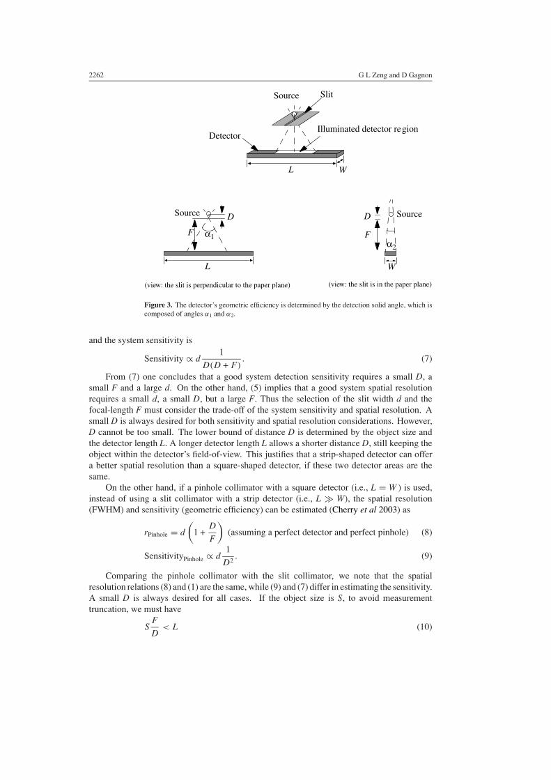
Figure 3. The detector’s geometric efficiency is determined by the detection solid angle, which iscomposed of angles α1 and α2.
and the system sensitivity is
Sensitivity ∝ d1
D(D + F). (7)
From (7) one concludes that a good system detection sensitivity requires a small D, asmall F and a large d. On the other hand, (5) implies that a good system spatial resolutionrequires a small d, a small D, but a large F. Thus the selection of the slit width d and thefocal-length F must consider the trade-off of the system sensitivity and spatial resolution. Asmall D is always desired for both sensitivity and spatial resolution considerations. However,D cannot be too small. The lower bound of distance D is determined by the object size andthe detector length L. A longer detector length L allows a shorter distance D, still keeping theobject within the detector’s field-of-view. This justifies that a strip-shaped detector can offera better spatial resolution than a square-shaped detector, if these two detector areas are thesame.
On the other hand, if a pinhole collimator with a square detector (i.e., L = W ) is used,instead of using a slit collimator with a strip detector (i.e., L � W), the spatial resolution(FWHM) and sensitivity (geometric efficiency) can be estimated (Cherry et al 2003) as
rPinhole = d
(1 +
D
F
)(assuming a perfect detector and perfect pinhole) (8)
SensitivityPinhole ∝ d1
D2. (9)
Comparing the pinhole collimator with the slit collimator, we note that the spatialresolution relations (8) and (1) are the same, while (9) and (7) differ in estimating the sensitivity.A small D is always desired for all cases. If the object size is S, to avoid measurementtruncation, we must have
SF
D< L (10)
CdZnTe strip detector SPECT imaging with a slit collimator 2263
Collimator slit
CdZnTe detector
Point source
Distance ρ from the point source to detector cell
The angle α on the integral plane
Integral plane on whichthe planar integral of theobject is defined for adetector cell.
A detector cellβ
F
Figure 4. Definition of some imaging parameters.
where F/D is the magnification factor for pinhole and slit-hole imaging geometries. Ifthe focal-length F is chosen to be the same for these two imaging geometries and thedetection areas are kept the same, the D value for the slit-hole/strip-detector configurationcan be smaller than the D value for the pinhole/square-detector configuration, because the Lvalue of the slit-hole/strip-detector configuration is larger than the L value of the pinhole/square-detector configuration. As a result, the slit-hole/strip-detector configuration is able toprovide better spatial resolution.
For example, in our prototype CdZnTe detector, Lslit = 345 mm and Wslit = 53 mm, andthe detection area is 18 285 mm2. If a square detector were built with the same detection area,the side-length would be Lsquare = √
18 285 = 135.22 mm. The shortest D value from (10)for the slit detector is Dslit = SF/Lslit, and for the square detector is Dsquare = SF/Lsquare.Using (1) and (8), for an object of a size S = 70 mm, the resolution ratio is
rsquare
rslit=
1 + SLsquare
1 + SLslit
= 1 + 70135.22
1 + 70345
= 1.26. (11)
In this example, there is a 26% improvement in spatial resolution by using a strip detector overa square detector.
2.3. Image reconstruction algorithms
Due to the nature of convergent beam measurements, the 3D image reconstruction cannotbe decomposed into a series of 2D slice-by-slice image reconstruction. Two analyticalreconstruction algorithms are proposed in this section.
2.3.1. Analytical algorithm I. The measurements of this imaging system are weighted planarintegrals, instead of line integrals, because a 1D array of pixels is used on the CdZnTe detector.Assuming that the detector width is small, the weighting factor in the planar measurement canbe approximated by
factor = cos α
ρsin β (12)
where ρ, α and β are defined in figure 4. An empirical pre-scaling factor |sin β|3/2 has beenchosen by trial-and-error with computer simulations, to make the reconstruction of a uniformsphere to be almost constant in the central image slice. The pre-scaling factor |sin β|3/2 is firstapplied to the projection measurements.
2264 G L Zeng and D Gagnon
t
pθ t( )
θ
Rebinning
Parallel planar integrals
Convergent planar integrals
Rebinning
Not available from circularorbit measurements
θpθ t( )
t
(a)
(b)
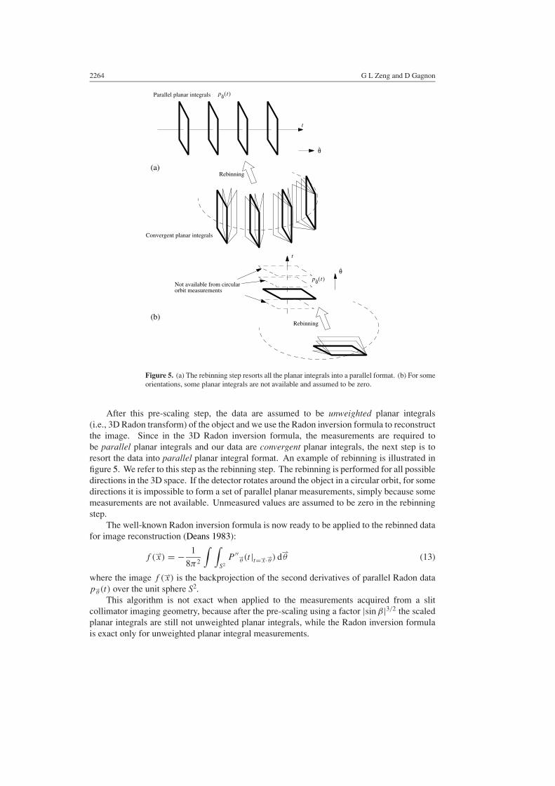
Figure 5. (a) The rebinning step resorts all the planar integrals into a parallel format. (b) For someorientations, some planar integrals are not available and assumed to be zero.
After this pre-scaling step, the data are assumed to be unweighted planar integrals(i.e., 3D Radon transform) of the object and we use the Radon inversion formula to reconstructthe image. Since in the 3D Radon inversion formula, the measurements are required tobe parallel planar integrals and our data are convergent planar integrals, the next step is toresort the data into parallel planar integral format. An example of rebinning is illustrated infigure 5. We refer to this step as the rebinning step. The rebinning is performed for all possibledirections in the 3D space. If the detector rotates around the object in a circular orbit, for somedirections it is impossible to form a set of parallel planar measurements, simply because somemeasurements are not available. Unmeasured values are assumed to be zero in the rebinningstep.
The well-known Radon inversion formula is now ready to be applied to the rebinned datafor image reconstruction (Deans 1983):
f (⇀x) = − 1
8π2
∫ ∫S2
P ′′⇀θ (t |t=⇀x·⇀θ ) d
⇀θ (13)
where the image f (⇀x) is the backprojection of the second derivatives of parallel Radon datap⇀
θ(t) over the unit sphere S2.This algorithm is not exact when applied to the measurements acquired from a slit
collimator imaging geometry, because after the pre-scaling using a factor |sin β|3/2 the scaledplanar integrals are still not unweighted planar integrals, while the Radon inversion formulais exact only for unweighted planar integral measurements.
CdZnTe strip detector SPECT imaging with a slit collimator 2265
x
y
z
12.6 mm
50.4 mm
1.8 mm
9 mm
5.4 mm
Spinning around thedetector’s axis
Rotating around the object slit
detector
φ
θ
z
50.4 mm
40 mm
200 mm
345.6 mm
Figure 6. Computer simulation set-up and computer generated phantom used for simulations: alarge sphere containing four smaller cold spherical lesions. The centres of the lesions are on the xand y axes, and 12.6 mm away from the centre of the large sphere (i.e., the origin). The intensityratio is 2.1; the large sphere has a higher intensity.
2.3.2. Analytical algorithm II. Analytical algorithm I mentioned above is essentially the 3DRadon inversion algorithm with a pre-scaling step and a convergent-to-parallel geometricalrebinning step. Another possible reconstruction method is to modify a cone-beam imagereconstruction algorithm, for example, Grangeat’s algorithm (Grangeat 1991). The resultantconvergent slit algorithm is as follows.
First, the projection data are first scaled by pre-scaling factor |sin β|−5/4, which havebeen selected by trial-and-error using computer simulations, to make the reconstruction of auniform sphere to be almost constant in the central image slice. This step is similar to that inanalytical algorithm I except that a different pre-scaling factor is used.
Second, a derivative is taken along the 1D detection array for each angular position.Analytical algorithm I does not have this step.
Third, the data are rebinned from the convergent format into parallel format. The rebinningprocedure is the same as in analytical algorithm I.
2266 G L Zeng and D Gagnon
(a)
(b)
(c)
x
y x
z
y
z
(a)
(b)
Figure 7. Computer simulation results with noiseless data: three orthogonal central slices inthe reconstructed image. (a) Analytical algorithm I is used. (b) Analytical algorithm II is used.(c) Profiles along the y-axis.
Forth, at each angular direction a derivative is taken for the rebinned data. On the otherhand, a second-order derivative is taken in algorithm I.
The final step is backprojection, similar to that in (13). Neither algorithm I nor algorithm IIis exact reconstruction algorithm. As will be demonstrated in computer simulations, algorithmII gives a more accurate reconstruction than algorithm I.
3. Computer simulation and phantom experiment
3.1. Computer simulations
In computer simulations, a spherical phantom as shown in figure 6 was used. The diameter ofthe large sphere was 50.4 mm. The diameters of the four smaller cold spheres were 12.6, 9,5.4 and 1.8 mm, respectively. The centres of the four cold spheres were on the detector orbitplane. The activity in the large sphere was 10. The smaller spheres had an activity density of 5.The detector pixel size was 1.8 mm, and there were 192 pixels on the detector. The distancefrom the slit to the detector (i.e., the focal length F) was 200 mm. The distance between theslit and the axis of rotation (φ) was 40 mm.
During data acquisition, there were 128 views for spinning angle θ over 360◦, and therewere 120 SPECT-views for rotation angle φ over 360◦. The cos α sin β/ρ weighting factorwas included in projection data generation; however, no attenuation or scatter was included
CdZnTe strip detector SPECT imaging with a slit collimator 2267
(a)
(b)
x
y x
z
y
z
Figure 8. Computer simulation results with noisy data: three orthogonal central slices in thereconstructed image. (a) Analytical algorithm I is used. (b) Analytical algorithm II is used.
in projection data generation. A perfect slit was assumed, that is, d was arbitrarily small.Two data sets were generated. One projection data set was noiseless, while Poisson noise wasadded in the second projection data set. The image was reconstructed in a 192 × 192 × 192array.
The reconstruction results with noiseless data are shown in figure 7. The reconstructionresults with noisy data are shown in figure 8. The computer reconstruction code was writtenin IDL, which is an interactive data language developed by Research Systems, Inc., Boulder,Colorado, USA. The backprojection step was implemented using Marr’s fast backprojectionmethod (Marr et al 1980).
The profiles in figure 7 are drawn along the y-axis in each reconstructed image volume,and they illustrate that the analytical algorithm II gives a more accurate reconstruction thanalgorithm I. The z-direction blurring and distortion are mainly caused by the incomplete dataacquired by a circular (SPECT rotation) orbit. This circular orbit can only provide sufficientdata for the region close to the orbit plane.
3.2. Phantom experiments
A prototype CdZnTe gamma camera with a slit collimator was built by Philips MedicalSystems in Cleveland. An AXISTM two-detector system was modified, and head no. 1 wasreplaced with a spinning CdZnTe camera. The other head (i.e., head no. 2) was unchangedand remained to be a NaI(Tl) detector (see figure 9(a)). The NaI(Tl) head was mounted witha pinhole collimator, with a pinhole diameter of 1 mm. The distance from the pinhole to thedetector was 16 cm. The CdZnTe head was mounted with a slit collimator, with a slit widthof 0.6 mm and a slit length of 130 mm. The distance from the slit to the director was 17.5 cm.The gantry rotated around 360◦ with 120 stops. Imaging time at each stop was 60 s and the
2268 G L Zeng and D Gagnon
(a)
(b)
Pinholecollimator
Slitcollimator
Micro Deluxephantom
Figure 9. Phantom experiment set-up: (a) a Philips/Marconi AXISTM SPECT system is modified.Head no 2 (as shown as the upper head) contains the NaI(Tl) detector with a pinhole collimatormounted. Head no 1 (as shown as the lower head) contains a rotating CdZnTe detector with a slitcollimator mounted. (b) A close-up view of the micro Deluxe phantom being imaged.
total imaging time was 2 h. The CdZnTe detector/collimator unit continuously span and theprojection data were binned into 512 spin angles at each stop. The CdZnTe detector had 192pixels and the pixel width was 1.8 mm. A 512 × 512 matrix was used to store projection datafor the NaI(Tl)/pinhole imaging configuration, and the detector pixel width was 1.17 mm.
The projection data sets for both imaging detectors were acquired simultaneously withthe identical scanning time. The detection area of the CdZnTe detector was 34.5 cm ×5.3 cm = 182.85 cm2. The detection area for the NaI(Tl) detector was 54 cm × 40 cm =2160 cm2. The NaI(Tl) was about 12 times larger than the CdZnTe detector. During the2 h scan, the CdZnTe detector collected 6.99 × 10⁸ photon counts and the NaI(Tl) collected1.25 × 107 photon counts. The slit (slit width = 0.6 mm) configuration had 56 more countsthan the pinhole (pinhole diameter = 1 mm) configuration. The slit configuration could collecteven more photons if the slit width were 1 mm wide.
A micro Deluxe PhantomTM (Data Spectrum Corporation, Hillsborough, NC, USA) wasused in the phantom experiment. The phantom had an outside diameter of 5 cm, and containedsix sections of small cold rods with diameters: 1.2, 1.6, 2.4, 3.2, 4.0 and 4.8 mm, respectively(see figure 10(a)). The height of the rods was 3.4 cm. The phantom was filled with 29 mCi(1.073 GBq) of Tc-99m. The phantom was positioned such that the distance between thephantom and the collimators was made as small as possible before data truncation occurred.
CdZnTe strip detector SPECT imaging with a slit collimator 2269
(a)
(b) (c)
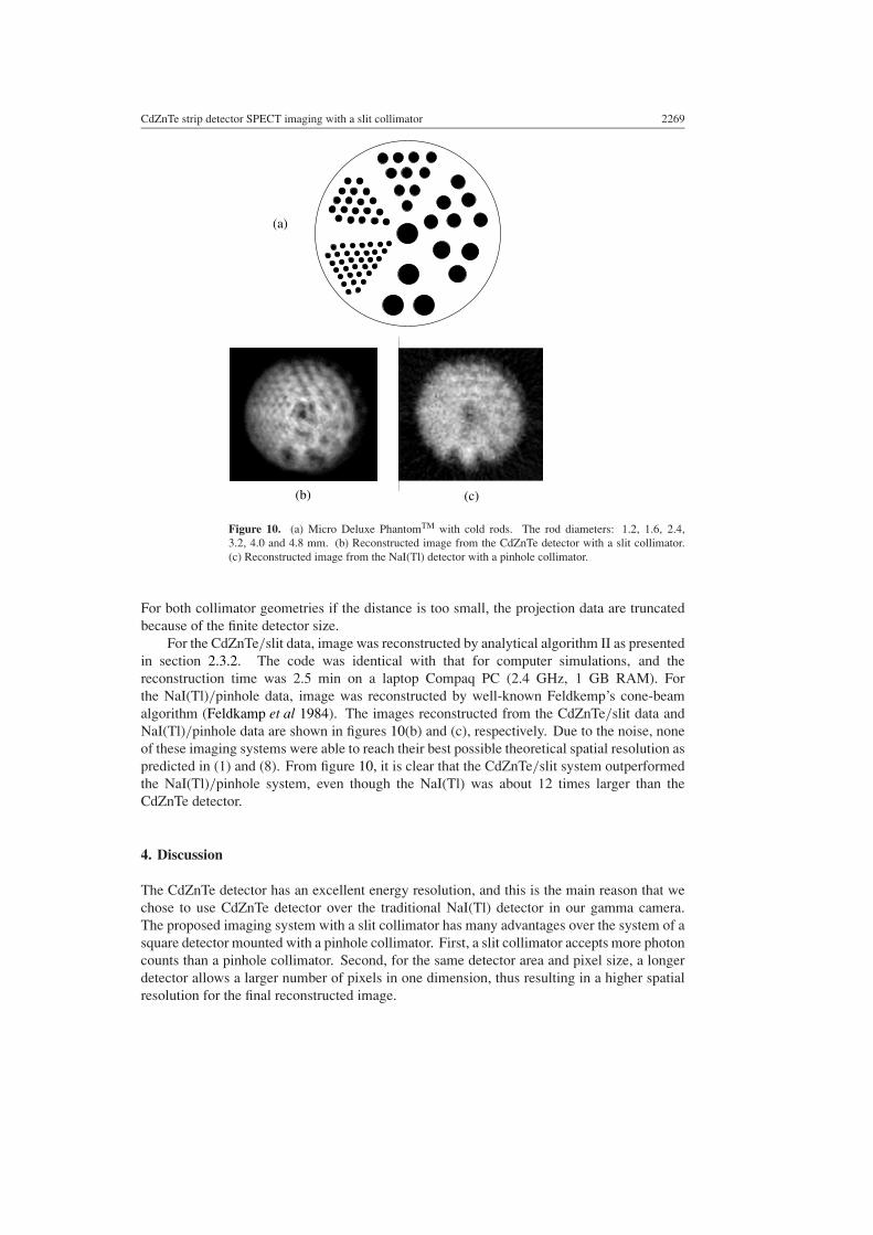
Figure 10. (a) Micro Deluxe PhantomTM with cold rods. The rod diameters: 1.2, 1.6, 2.4,3.2, 4.0 and 4.8 mm. (b) Reconstructed image from the CdZnTe detector with a slit collimator.(c) Reconstructed image from the NaI(Tl) detector with a pinhole collimator.
For both collimator geometries if the distance is too small, the projection data are truncatedbecause of the finite detector size.
For the CdZnTe/slit data, image was reconstructed by analytical algorithm II as presentedin section 2.3.2. The code was identical with that for computer simulations, and thereconstruction time was 2.5 min on a laptop Compaq PC (2.4 GHz, 1 GB RAM). Forthe NaI(Tl)/pinhole data, image was reconstructed by well-known Feldkemp’s cone-beamalgorithm (Feldkamp et al 1984). The images reconstructed from the CdZnTe/slit data andNaI(Tl)/pinhole data are shown in figures 10(b) and (c), respectively. Due to the noise, noneof these imaging systems were able to reach their best possible theoretical spatial resolution aspredicted in (1) and (8). From figure 10, it is clear that the CdZnTe/slit system outperformedthe NaI(Tl)/pinhole system, even though the NaI(Tl) was about 12 times larger than theCdZnTe detector.
4. Discussion
The CdZnTe detector has an excellent energy resolution, and this is the main reason that wechose to use CdZnTe detector over the traditional NaI(Tl) detector in our gamma camera.The proposed imaging system with a slit collimator has many advantages over the system of asquare detector mounted with a pinhole collimator. First, a slit collimator accepts more photoncounts than a pinhole collimator. Second, for the same detector area and pixel size, a longerdetector allows a larger number of pixels in one dimension, thus resulting in a higher spatialresolution for the final reconstructed image.
2270 G L Zeng and D Gagnon
Similar to the situation with the pinhole collimator, a rotating slit collimator does notmeasure a complete data set when the detector rotates in a circular (planar) orbit. Imaginggeometries that can provide a complete data set as well as multi-slit imaging geometries areunder investigation and will be reported in future publications.
Acknowledgments
This work was supported by the National Institute of Biomedical Imaging and Bioengineeringof the National Institutes of Health under grants R33-EB001489 and R21-EB003298. Wethank Mr David Mercer of Philips Medical Systems (Cleveland) and Dr Zhenghong Lee ofCase Western Reserve University for assistance in phantom experiments.
References
Anger R T 1984 The Anger scintillation camera—a review Physics of Nuclear Medicine, Recent Advancesed D V Rao, R Chandra and R Graham (New York: American Institute of Physics) pp 59–67
Barber H B et al 1997 Development of a 64 × 64 CdZnTe array and associated readout integrated circuit for use innuclear medicine 1996 U.S. Workshop on the Physics and Chemistry of II–VI Materials vol 26, pp 765–72
Beque D, Nuyts J, Bormans G, Suetens P and Dupont P 2003 Characterization of pinhole SPECT acquisition geometryIEEE Trans. Med. Imaging 22 599–612
Butler J F et al 1998 CdZnTe solid-state gamma camera IEEE Trans. Nucl. Sci. 45 359–63Cherry S R, Sorenson J A and Phelps M E 2003 Physics in Nuclear Medicine 3rd edn (Philadelphia, PA: Saunders)Deans S R 1983 The Radon Transform and Some of its Applications (New York: Wiley)Entine G, Luthmann R, Mauderli W, Fitzgerald T, Williams C M and Tosswill C H 1979 Cadmium telluride gamma
camera IEEE Trans. Nucl. Sci. 26 552–8Eskin J D, Barber H B and Barrett H H 1996 Variations in pulse-height spectrum and pulse timing in CdZnTe pixel
array detectors Proc. SPIE—Int. Soc. Opt. Eng. 2859 46–9Eskin J D, Barrett H H and Barber H B 1999 Signals induced in semiconductor gamma-ray imaging detectors J. Appl.
Phys. 85 647–59Feldkamp L A, Davis L C and Kress J W 1984 Practical cone-beam algorithm J. Opt. Soc. Am. A 1 612–9Gagnon D, Zeng G L, Griesmer J J, Valentino F C and Links J M 2001 Design considerations for a new solid-state
gamma camera: Solstice Conference Record of IEEE Nucl. Sci. Med. Imaging Conf. vol 2, pp 1156–60Gindi G R, Arendt J, Barrett H H, Chiu M Y, Ervin A, Giles C L, Kujoory M A, Miller E L and Simpson R G 1982
Med. Phys. 9 324–39Grangeat P 1991 Mathematical framework of cone-beam 3D reconstruction via the first derivative of the Radon
transform Mathematical Methods in Tomography (Lecture Notes in Mathematics vol 1497) ed G T Herman,A K Louis and F Natterer (Berlin: Springer) pp 66–97
Griesmer J J, Kline B, Grosholz J, Parnham K and Gagnon D 2001 Design considerations for a new solid-state gammacamera: Solstice Conference Record of IEEE Nucl. Sci. Med. Imaging Conf. vol 2, pp 1150–4
Habraken J B A, de Bruin K, Shehata M, Booij J, Bennink R, van Eck Smit B L F and Sokole E B 2001 Evaluationof high-resolution pinhole SPECT using a small rotating animal J. Nucl. Med. 42 1863–9
Jaszczak R J, Li J, Wang H, Zalutsky M R and Coleman R E 1994 Pinhole collimation for ultra-high-resolution,small-field-of-view SPECT Phys. Med. Biol. 39 425–37
Kastis G A, Barber H B, Barrett H H, Balzer S J, Lu D, Marks D G, Stevenson G, Woolfenden J M, Appleby M andTueller J 2000a Gamma-ray imaging using a CdZnTe pixel array and a high-resolution, parallel-hole collimatorIEEE Trans. Nucl. Sci. 47 1923–27
Kastis G A et al 2000b Tomographic small-animal imaging using a high-resolution semiconductor camera 2000 IEEENucl. Sci. Symp. Med. Imaging Conf. Rec. vol 3, pp 31–5
Keyes W I 1975 The fan-beam gamma camera Phys. Med. Biol. 20 489–91Kujoory M A, Miller E L, Barrett H H, Gindi G R and Tamura P N 1980 Coded aperture imaging of gamma-ray
sources with an off-axis rotating slit Appl. Opt. 19 4186–95Malm H L, Mauderli W, Urie M, Fitzgerald L and Williams C N 1982 A germanium laminar emission camera IEEE
Trans. Nucl. Sci. 29 465–8Marks D G et al 1995 A 48 × 48 CdZnTe array with multiplexer readout 1995 IEEE Nucl. Sci. Symp. Med. Imaging
Conf. Rec. vol 2, pp 752–6
CdZnTe strip detector SPECT imaging with a slit collimator 2271
Marks D G, Barber H B, Barrett H H and Woolfenden J M 1998 Improving spatial resolution in semiconductorgamma-ray detectors using a list-mode EM algorithm for fluence estimation 1998 IEEE Nucl. Sci. Symp. Med.Imaging Conf. Rec. 1 657–61
Marks D G, Barber H B, Barrett H H, Tueller J and Woolfenden J M 1999 Improving performance of a CdZnTeimaging array by mapping the detector with gamma rays Nucl. Instrum. Methods Phys. Res. A 428 102–12
Marr R B, Chen C and Lauterbur P C 1980 On two approaches to 3D reconstruction in NMR zeugmatographyMathematical Aspects of Computerized Tomography ed G T Herman and F Natterer (New York: Springer)
Matherson K J, Barber H B, Barrett H H, Eskin J D, Dereniak E L, Woolfenden J M, Young E T and Augustine F L1988 Progress in the development of large-area modular 64 × 64 CdZnTe imaging arrays for nuclear medicineIEEE Trans. Nucl. Sci. 45 354–8
Matherson K J, Barber H B, Barrett H H, Eskin J D, Derniak E L, Marks D G, Woolfenden J M, Young E T andAugustine F L 1998 Progress in the development of large-area modular 64 × 64 CdZnTe imaging arrays fornuclear medicine IEEE Trans. Nucl. Sci. 45 354–8
Mauderli W, Luthmann R W, Fitzgerald L T, Urie M M, Williams C M, Tosswill C H and Entine G 1979 Acomputerized rotating laminar radionuclide camera J. Nucl. Med. 20 341–4
Mauderli W, Fitzgerald L T, Urie M M and Tosswill C H 1981 Rotating laminar emission camera with Ge-detector: ananalysis Med. Phys. 8 871–6
Mauderli W and Fitzgerald L T 1987 Rotating laminar emission camera with Ge-detector: further developmentsMed. Phys. 14 1027–31
McElroy D P, MacDonald L R, Beekman F J, Wang Y, Patt B E, Iwanczyk J S, Tsui B M W and Hoffman E J 2002Evaluation of A-SPECT: a desktop pinhole SPECT system for small animal imaging IEEE Trans. Nucl. Sci.49 2139–47
Meikle S R, Kench P, Weisenberger A G, Wojcik R, Smith M F, Majewski S, Eberl S, Fulton R R, Rosenfeld A Band Fulham M J 2002 A prototype coded aperture detector for small animal SPECT IEEE Trans. Nucl. Sci. 492167–71
Rudin S and Bednarek D R 1980 Rotating aperture devices in X-ray tomography Proc. Soc. Photo-Opt. Instrum. Eng.233 32–42
Schramm N U, Ebel G, England U, Schurrat T, Behe M and Behr T M 2003 High-resolution SPECT usingmultipinhole collimation IEEE Trans. Nucl. Sci. 50 315–20
Smith M F, Majewski S, Meikle S R, Weisenberger A G, Popov V and Wojcik R F 2002 Design of high sensitivity,high resolution compact single photon imaging devices for small animal and dedicated breast imagingConference Record of 2001 IEEE Nucl. Sci. Symp. Med. Imaging Conf. vol 3, pp 1592–6
Song T Y, Choi Y, Chung Y H, Jung J H, Choe Y S, Lee K H, Kim S E and Kim B T 2003 Optimization of pinholecollimator for small animal SPECT using Monte Carlo simulation IEEE Trans. Nucl. Sci. 50 327–32
Touma H 1993 Synthetic aperture technique in astronomy using slit aperture telescope Astrophys. Space Sci. 25847–53
Tsui B M W, Wang Y, Yoder B C and Frey E C 2002 Micro-SPECT IEEE Int. Symp. Biomed. Imaging pp 373–6Urie M M, Mauderli W, Fitzgerald L T, Williams C M and Tosswill C H 1981 Rotating laminar emission camera
with Ge-detector Med. Phys. 8 865–70Webb S, Binnie D M, Flower M A and Ott R J 1992 Monte Carlo modelling of the performance of a rotating
slit-collimator for improved planar gamma-camera imaging Phys. Med. Biol. 37 1095–108Webb S, Flower M A and Ott R J 1993 Geometric efficiency of rotating slit-collimator for improved planar gamma-
camera imaging Phys. Med. Biol. 38 627–38Weber D A et al 1994 Pinhole SPECT: an approach to in vivo high resolution SPECT imaging in small laboratory
animals J. Nucl. Med. 35 342–8Wilson D W, Barrett H H and Furenlid L R 2002 A new design for a SPECT small-animal imager Conference Record
of 2001 IEEE Nucl. Sci. Symp. Med. Imaging Conf. vol 3, pp 1826–9Woolfenden J M, Barber H B, Barrett H H, Dereniak E L, Eskin J D, Marks D G, Matherson K J, Young E T and
Augustine F L 1998 Modular 64 × 64 CdZnTe arrays with multiplexer readout for high-resolution nuclearmedicine imaging Infrared Appl. Semicond. II Symp. pp 267–71
Wu M C, Hasegawa B H and Dae M W 2002 Performance evaluation of a pinhole SPECT system for myocardialperfusion imaging of mice Med. Phys. 29 2830–9
Wu M C, Kastis G A, Balzer S J, Wilson D W, Barber H B, Barrett H H, Dae M W and Hasegawa B H 2000High-resolution SPECT with a CdZnTe detector array and a scintillation camera 2000 IEEE Nucl. Sci. Symp.Med. Imaging Conf. Rec. pp 376–80