14
CE 435 Embedded Systems Spring 2019 LAB1 Implementation of Gray Counter on an FPGA
CE 435
Embedded Systems
Spring 2019
LAB1 Implementation of Gray Counter
on an FPGA

CE435 Embedded Systems 1
Introduction
Lab1 is about functional simulation and implementation of a Gray Counter in Verilog using
the Xilinx Vivado toolset. At the end of lab1, you will be able to download and test your design
on Zedboard.
The Zedboard digital system development platform features Xilinx's newest Zynq-7000 FPGA,
512 MB external DDR3 memory and enough I/O devices and ports to host a wide variety of
digital systems.
Objectives
The objective of these lab sessions are the following:
a) to introduce the concepts of hardware design using Verilog HDL ,
b) to introduce functional and timing simulation and debugging using testbenches and the
Xilinx Vivado simulator,
c) to introduce the concepts of user-constrained design synthesis, placement, routing and
bitmap generation on a Xilinx FPGA board,
d) to introduce the downloading and demonstration of the design on the board, and
e) to introduce the functionality of the Zedboard.
The diagram shows the typical design flow that will be followed in this lab.
Gray code
The concept of a gray counter is that only one bit changes between 2 successive codes. The 2-bit
Gray code is: 00 01 11 10, and the 3-bit Gray code is: 000 001 011 010 110 111 101 100.

CE435 Embedded Systems 2
The binary-reflected Gray code for n bits can be generated recursively by reflecting the bits (i.e.
listing them in reverse order and concatenating the reverse list onto the original list), prefixing the
original bits with a binary 0 and then prefixing the reflected bits with a binary 1. For example, the
4-bit Gray code can be constructed by reflecting the 3-bit code:
0000 0001 0011 0010 0110 0111 0101 0100 1100 1101 1111 1110 1010 1011 1001 1000
(0)+3 bit Gray Code (1)+reflected 3 bit Gray Code
Lab overview The lab will build a 4-bit Gray code for demonstration on the Xilinx Zedboard. This is an
evaluation board that includes a Zynq-7000 FPGA (XC7Z020), 512 MB external DDR3 and Flash
memories, and a series of peripherals to be used for our demonstration. In this lab, we will use four
of the GPIO LEDs (General Purpose I/O Light Emitting Diodes) located at the bottom of the board.
The following Fig. shows the top level of the design. The LEDS will switch every second
(freq=1Hz) between successive 4-bit Gray code. Before we implement the design on the FPGA
board, we will need to simulate it (step1).
Xilinx tools set up Make sure that your Linux environment is set up for the Xilinx Vivado toolset. Run (or, even better,
place in your start-up shell script) the following commands:
setenv XILINXD_LICENSE_FILE [email protected]
source /opt/Xilinx/Vivado/2017.2/settings32.csh #for 32-bit linux OR

CE435 Embedded Systems 3
source /opt/Xilinx/Vivado/2017.2/settings64.csh #for 64-bit linux
The two previous script commands refer to csh shell, and the start-up shell script is .cshrc, which should
be placed in your home directory. Every time you launch a new csh terminal, the .cshrc script is
automatically executed. The number 14.2 refers to the Xilinx tools version.
Step1 - Design and behavioral simulation of 4-bit Gray counter
In this first step of lab1, you will implement a 4-bit Gray code using a Finite State Machine
(FSM) in Verilog. You will write a test bench and simulate, debug and test your design using the
builtin Vivado simulator of Xilinx. If you prefer, you can also use Modelsim to simulate your
designs.
The purpose of this module is to get a general understanding on designing, simulating and
debugging your hardware described in Verilog. This task is usually accomplished using a test
bench which can also be written in Verilog. Therefore, it is important to understand that a Verilog
test bench is as error prone as a Verilog hardware description.
This step requires that you fill in the details of the design and the test bench files and
simulate the design until you are convinced that it generates a valid sequence of 4-bit Gray
codes.
Start this lab by copying the input files of the module into your local folder and study the two
skeleton Verilog files. You have to write Verilog code to generate the sequence described in the
Overview Document using an FSM which changes states on the rising edge of the clock. When
the asynchronous reset signal is asserted, the state becomes 4’b0000 (Gray_4bits_RTL.v).
Now we will turn our attention to the code of the test bench (TB1_Gray.v). In the test bench,
the gray counter is instantiated and its inputs are connected to signals that are generated in the test
bench. The outputs of the gray counter are connected to signals that are verified. Besides the
instantiation of the gray counter, there are also some other important behavioral statements
(initial, always):
There is one initial statement that initializes system signals such as reset, clk and
EndOfSimulation and sets the EndOfSimulation after a particular number of clock
signals. Another behavioral statement generates the clock signal with a period cycle. This
requires that the clk signal reverses after cycle/2 ns.
1. Once you are satisfied that your code makes sense, launch Vivado from a linux terminal to
create a new design project (make sure that you have already set the tools up as described in
the Overview document):
% vivado &
The Vivado Project Navigator GUI will open.
2. You create a new project: Create New Project
3. At the Create New Vivado Project page click Next
4. For Project Location, browse to your preferred directory. Type the Project Name
(e.g.GrayCounter_4bit) and make sure that the Create Project subdirectory is checked. Click
Next.
5. In the Project Type form select RTL Project. Click Next.
6. Click Next a few times till you reach the Default Part page.

CE435 Embedded Systems 4
7. In the Default Part form specify Boards and start searching for Zedboard. Select Zedboard
Zynq Evaluation and Development Kit.
8. In the New Project Summary form click Finish to create the project.
Figure 1 shows the Vivado IDE environment:
1. Menu Bar
2. Main Toolbar
3. Flow Navigator
4. Layout Selector
5. Data Windows Area
6. Workspace
7. Menu Command Search Field
8. Project Status Bar
9. Status Bar
10. Results Window Area
Select Add Sources in the Flow Navigator, then select Add or Create Design Sources and click
Next. Select Add Files, browse to the directory where your Verilog code resides to add the two
Verilog files that you created for this project and click Next and Finish. The Project Manager view
will be updated to illustrate the hierarchy of your design.
The next step is to use the Vivado built-in simulator and examine the behavioral simulation
results. Behavioral simulation only simulates the Verilog code without any inference to gates or
Figure 1. Vivado IDE Viewing Environment

CE435 Embedded Systems 5
transistors and is used to prove the logical correctness of your Verilog code. In the Flow Navigator,
under the Simulation tab, select the Simulation Settings button and make sure that the Target
Simulator is Vivado, the Simulator Language is mixed (or Verilog), and that the top module name
is the name of your testbench module. Press OK. In the Flow Navigator, press Run Simulation and
Run Behavioral Simulation.
The Verilog code will be compiled and executed using the testbench as the top level module. The
workspace of the Vivado IDE will change and new windows will appear when you execute the
testbench. One window shows the simulation results as waveforms, another shows the Objects of
test bench and yet another the hierarchy of the design and the glbl instances (Scopes). The Main
Toolbar can be used to guide the simulation. The most widely used icons are: restart which resets
the simulation and the waveform and run <time> which runs the simulator for time N. For
example, run 10000 ns will run the design for 10000 ns and will terminate. You can move around
the hierarchy of your design from the Scopes window, select signals and variables that you want to
trace and simulate from the Objects window, and drag them to the waveform window.
Test your simulation to ensure that it is correct. Exit when you are done simulating.
Go to the project directory and check to see the directory structure that Vivado created to store
the files for project support. The <Project Name>.srcs directory contains all project source files
and design constraints (to be explained later in step 4). The <Project Name>.sim directory contains
automatically generated files for each simulation campaign. The <Project Name>.data directory is
a placeholder for the Vivado program database.
Step 2 - N-bit Gray counter One of the features of Verilog is that it enables you to create parameterized hardware systems. In
this lab you will learn you will how to use such parameter in order to build a general N bit gray
counter.
The architecture of an N bit gray counter cannot be easily deduced from the code used in step
1. In order to make a general N bit gray counter you will have to use an N+1 bit register, in which
the purpose of the LSB is to act as an auxiliary bit.
This auxiliary bit is not part of the final gray counter but is necessary to calculate the next
value of the gray counter. In order to clarify this, let’s take a look at an example: a 4 bit gray
counter that implements this auxiliary bit.
If you write down the successive gray codes for a 4 bit gray counter and you add an LSB that
starts at 1 and toggles, you will get next sequence:
0000 1 start value
0001 0 value after first clock edge
0011 1 value after second clock edge
0010 0
0110 1
0111 0
0101 1
0100 0
1100 1 1101 0
1111 1
1110 0
1010 1
1011 0
1001 1
1000 0
0000 1 back to start value
. . .
. . .
CE435 Embedded Systems 6
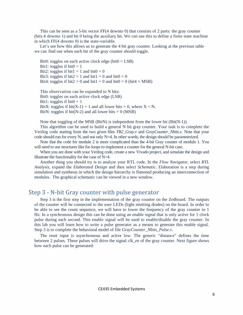
This can be seen as a 5-bit vector FF(4 downto 0) that consists of 2 parts: the gray counter
(bits 4 downto 1) and bit 0 being the auxiliary bit. We can use this to define a finite state machine
in which FF(4 downto 0) is the state-variable.
Let’s see how this allows us to generate the 4 bit gray counter. Looking at the previous table
we can find out when each bit of the gray counter should toggle.
Bit0: toggles on each active clock edge (bit0 = LSB)
Bit1: toggles if bit0 = 1
Bit2: toggles if bit1 = 1 and bit0 = 0
Bit3: toggles if bit2 = 1 and bit1 = 0 and bit0 = 0
Bit4: toggles if bit2 = 0 and bit1 = 0 and bit0 = 0 (bit4 = MSB)
This observation can be expanded to N bits:
Bit0: toggles on each active clock edge (LSB)
Bit1: toggles if bit0 = 1
BitX: toggles if bit(X-1) = 1 and all lower bits = 0, where X < N.
BitN: toggles if bit(N-2) and all lower bits = 0 (MSB)
Note that toggling of the MSB (BitN) is independent from the lower bit (Bit(N-1)).
This algorithm can be used to build a general N bit gray counter. Your task is to complete the
Verilog code starting from the two given files TB2_Gray.v and GrayCounter_Nbits.v. Note that your
code should run for every N, and not only N=4. In other words, the design should be parameterized.
Note that the code for module 2 is more complicated than the 4-bit Gray counter of module 1. You
will need to use structures like for-loops to implement a counter for the general N-bit case.
When you are done with your Verilog code, create a new Vivado project, and simulate the design and
illustrate the functionality for the case of N=4.
Another thing you should try is to analyze your RTL code. In the Flow Navigator, select RTL
Analysis, expand the Elaborated Design and then select Schematic. Elaboration is a step during
simulation and synthesis in which the design hierarchy is flattened producing an interconnection of
modules. The graphical schematic can be viewed in a new window.
Step 3 - N-bit Gray counter with pulse generator
Step 3 is the first step in the implementation of the gray counter on the Zedboard. The outputs
of the counter will be connected to the user LEDs (light emitting diodes) on the board. In order to
be able to see the count sequence, we will have to lower the frequency of the gray counter to 1
Hz. In a synchronous design this can be done using an enable signal that is only active for 1 clock
pulse during each second. This enable signal will be used to enable/disable the gray counter. In
this lab you will learn how to write a pulse generator as a means to generate this enable signal.
Step 3 is to complete the behavioral model of file GrayCounter_Nbits_Pulse.v.
The reset input is asynchronous and active low. The generic “distance” defines the time
between 2 pulses. These pulses will drive the signal clk_en of the gray counter. Next figure shows
how each pulse can be generated:

CE435 Embedded Systems 7
The time distance between two successive pulses is equal to 1 sec. The complete system is shown
below. The GrayCounter_Nbits_Pulse.v code implements the Gen_clk_en module and connects
the pulse signal to clk_en.
Next, you will need to implement the Gray_system.v module which instantiates the Gray and
Pulse modules.
Once you complete the Verilog programs, create a new Vivado project and instantiate the
Gray_system.v module in the test bench TB3_Gray.v, you should simulate the program using iSIM
and check the correct functionality.
Step 4 - N-bit Gray counter in FPGA The Gray counter that you verified in the previous module, will now be implemented on the
Zedboard board. The outputs of the gray counter will be connected to 4 (or 8) GPIO LEDs of the
board. You should have concluded the first three steps before you attempt this step. There is no
additional Verilog code for step 4.
After this step, the student should be able to implement a small hardware system on an FPGA
board. You will also learn details on the implementation flow of the Vivado toolset. Since this is the
first time that you use the Xilinx implementation tools, this lab is described as a walk-through in
which all steps are explained. Launch Vivado from a Linux terminal and create a new design project
(e.g. GrayCounter_Nbit_fpga):
% vivado &
Create the new project which includes the three Verilog files you created in Lab3 without the test
bench (refer to step1 for details on how to do this). We will not need a test bench file because we
will run the design on the board instead of simulating it. The file GrayCounter_System.v is the top

CE435 Embedded Systems 8
level of the design.
Design Constraints
Besides the verilog source code, an implementation to an FPGA bitstream requires that the
designer defines design constraints. These constraints specify the FPGA I/O pins which will be
assigned to the I/O module ports (e.g. clock, leds, etc.), their physical characteristics, timing
constraints such as clock period and clock duty cycle and so on. In particular timing are the most
important constraints of a design since they have a direct impact to the speed and area of the
generated circuit. There is an inverse relationship between area (i.e. number of LUTs) and speed
(i.e. clock frequency): aggressive clock frequencies typically result into circuits that are larger.
Select Add Sources in the Flow Navigator, then select Add or Create Constraints and click Next.
Select Add Files, and select the GrayCounter_System.xdc text file. For this lab, the incomplete
XDC file (XDC stands for Xilinx Design Constraints) is given to you. You will need to fill in the
details, i.e. the entries that contain XXX. You will have to consult the Zedboard schematic for the
pin locations of the clk, rst and leds (named LD0 to LD7) in the Zedboard schematic. It is actually
even easier in the Zedboard because the pin locations are the small codes near the leds. For
example led[0] is electrically connected to pin T22 of the FPGA. Study the syntax of the Tcl script
(pronounced as tikl) language that is used in the XDC file and try to extend it to all I/O pins.
Make also sure to specify a clock period of 10 ns (100M MHz target frequency). The XDC file is
where the Vivado tool is instructed by the user to perform time-constrained placement and routing
and to place the I/O ports of the design onto specific FPGA pins that have a dedicated function in
the board (e.g. they are connected to the LEDs or buttons). This is where you specify the target
clock frequency that you want your system to run.
An alternative way to specify design constraints is by the drop-down Layout Selector menu. In the
Flow Navigator, open the Elaborated Design, select I/O Planning and notice that the Package GUI
view is displayed in the Workspace area and the I/O ports tab in the Results Window Area (see
figure). Move the cursor over the Package view, highlighting different pins. Notice the pin site
number is shown at the bottom of the Vivado GUI, along with the pin type (User IO, GND,
VCCO…) and the type of the I/O bank it belongs to.

CE435 Embedded Systems 9
Expand the led ports by clicking on the + box and make sure that led[3:0] use the LVCMOS33 I/O
standard (change it if they do not). To assign a pin location for led[0], click under the site column
across led[0] row to see a drop-down box appear. Type T22, tick Fixed and hit the Enter key to
assign the pin.
Notice that any selection that you perform in this GUI automatically updated the XDC file which
has to be reloaded every time you make a change. In fact, the Package GUI is just a more user-
friendly method to specify design constraints. The specification of pin site T22 and LVCMOS33
I/O standard for led[0] is specified by the following two Tcl commands in the
GrayCounter_System.xdc file:
set_property package_pin T22 [get_ports{led[0]}]
set_property ionstandard_LVCMOS33 [get_ports{led[0]}]
Select FileSave Constraints and click OK to update the existing constraints file.
Synthesis
Synthesis is a process which parses the Verilog design files and generate a gate-level netlist for
the whole design. After synthesis there is no immediate correspondence between the gate level

CE435 Embedded Systems 10
netlist (GrayCounter_System.ngc) and the FPGA architecture. In other words, the netlist is in a
generic gate level format.
Click on Run Synthesis under Synthesis tab. The synthesis process will be run on the top level
GrayCounter_System.v file (and all its hierarchical files). When the process is completed after a
few minutes a Synthesis Completed dialog box with three options is displayed. Select the Open
Synthesized Design option and click OK as we want to look at the synthesis output before
progressing to the implementation stage. Click Yes to close the elaborated design if the dialog box
is displayed.
Select the Project Summary tab (Default Layout) and understand the various windows. You can see
useful information such as the utilization of the FPGA in terms of various resources such as LUT,
I/Os both in Graph and Table format. Click on the Schematic tab under the Open Synthesized
Design to view the synthesized design in schematic view. Study the schematics of both the gray
counter and pulse generator and observe that IBUF and OBUF gates are automatically
instantiated to the design as the input and output is buffered. These gates will be later mapped to
LUTs and Flip flops in the FPGA CLBs.
Verify that the <Project Name>.runs directory has been created by Vivado under the <Project
Name> directory. Under the runs directory, synth_1 directory is created which holds several
temporary subdirectories.
Implementation (Translation, Mapping, Placement & Routing)
The implementation is a multi-step phase that transforms the synthesized gate level netlist into a
Xilinx proprietary bitstream that can be downloaded to program the FPGA.
The translation phase merges multiple design files into a single netlist called
GrayCounter_System.ngd. This is the main data base of the netlist which also includes the
constraint file (XDC).
The Mapping phase groups gates from the netlist into physical components of the FPGA (LUTs,
Flip-flops, DSP modules, IO buffers, etc.).
The Placement and Routing phase places the physical components onto the 2D chip, connects the
components, and extract timing data into reports. This is the most time-consuming task of the
implementation phase.
Once a design is implemented, the user should create a file that can be downloaded and
program the FPGA. This file is called a bitstream: a BIT file (.bit extension), which can program
the FPGA in one of two different ways:
By a download cable such as a Platform USB. The bitstream is downloaded from the
computer hard disk to the FPGA.
By writing a non-volatile memory such as a Xilinx Platform Flash PROM. The bit file
should first be converted into a PROM file.
Click on Run Implementation under the Implementation tab. The implementation task will run
on the synthesis output files. When the process is completed an Implementation Completed dialog
box with three options is displayed. Select the Open Implemented Design option and click OK as
we want to look at the implementation output in the Device view tab. Click Yes to close the
synthesized design.
Study the implemented design in the Device view and zoom in to look at the details of the final
design and how it is mapped on the FPGA fabric. At the Netlist panel, select one of the nets and
notice that the net is highlighted in the FPGA.
Close the implemented view and select the Project Summary (Default Layout view) and observe

CE435 Embedded Systems 11
the results. How much is the actual resource utilization? Select the Post-implementation tabs under
the Timing and Utilization Windows.
Verify that the impl_1 directory has been created under the <Project Name>.runs directory. The
impl_1 directory contains several files including the report files.
Timing simulation
Now that the N-bit gray counter has been placed and routed in the Zynq-7000 FPGA fabric, we
have all the information to perform a detailed timing simulation. Click on Run Simulation Run
Post-implementation Timing Simulation under the Simulation tab. The Vivado simulator will be
launched using the implemented design and your testbench as the top level module. Note that
you have to resort to a previous project with a testbench in order to be able to run the simulation.
Run again the testbench and notice that the waveform show the real and not the zero delay of the
behavioral simulation. Close the simulator by selecting FileClose simulation
Bitstream generation and FPGA Programming
This step will allow us to download the design to the FPGA and see the N-bit gray counter
running on the Zedboard. First, you should connect the board, power it ON and make sure
that the micro-USB cable is connected between the board and the PC. All the jumpers JP7
to JP11 should be connected to the GND as shown in the figure. To be able to program the
FPGA, we should have already installed the cable drivers as described in a separate
document.
Once all these preparatory steps have been taken, select the Generate Bitstream entry
under Program and Debug in the Flow Navigator panel. The bitstream generation process
is used to generate the “executable” file that will be downloaded to the FPGA. It runs on

CE435 Embedded Systems 12
the implemented design and, when completed, a Bitstream Generation Completed dialog box
with three options will be displayed. The <Project Name>.bit file is generated under
impl_1 subdirectory under the <Project Name>.runs directory.
Select the Open Hardware Manager option and click OK. The Hardware session window
will open indicating “unconnected” status. Click on the Open a New Hardware Target link.
You can also click on the Open Recent Hardware Target if the board was already targeted
before.
Click Next to see the Vivado CSE server name. Click Next with the localhost port selected.
The JTAG cable will be searched and the Xilinx_tcf should be detected and identified as a
hardware target. It will also show the hardware devices detected in the chain. Click Next
twice and then Finish. The hardware status changes from Unconnected to the server name
and the device (i.e. the FPGA) is highlighted. Also notice that the status indicates that it is
not programmed. Select the device and verify that the <Project Name>.bit bitstream file is
selected as the programming file in the General tab. Right click on the device and select
Program Device to program the target FPGA device.
Click OK to program the FPGA with the selected bitstream file. The blue DONE light will
light immediately after the FPGA is programmed.
Once the last bit of the bitstream file makes it into the FPGA the design will start running.
Hopefully, everything has been done correctly and you can see the red LEDs blinking
according to the gray code.

CE435 Embedded Systems 13
Close the hardware session by selecting FileClose Hardware Manager.
Step 5 – Use Buttons to enable Gray Counter
Step 4 required that the Gray counter advances at a 1 Hz frequency without any interaction with the
user. Step 5 requires that the counter only advances each time the user presses a button. Each time the
user presses the button, the Gray counter will move to the next value, regardless of how long the button is
pressed. You should design and implement such a system on the FPGA.
The first step is to construct an edge detection module. This is an FSM-based module that receives as
input a multi-cycle pulse signal and generates as output a single-cycle pulse signal. The input pulse signal
is generated by the button in the board and can last any number of clock cycles. It corresponds to the user
pressing the button. However, such an input pulse that lasts multiple cycles N can trigger as many counter
increases as the number of cycles N, which is not what the user requires for the system.
This FSM-based edge detector will produce an output that can be connected to the clk_en signal of the
gray counter. The input to the edge detector is a button of the Zedboard.
What do you observe? Does your system work?
Debouncing
A problem arises from the mechanical "bounce" inherent in switches: as a metal contact opens and
closes it may bounce a couple of times, creating a sequence of on/off transitions in rapid succession. So
you need to use debouncing circuitry to filter out these unwanted transitions. You should design
debounce.v a Verilog implementation of a digital retriggerable one-shot that requires that an input
transition be stable for (approximately) T=0.01sec before reporting a transition on its output. You should
use an instance of the module to debounce any switch inputs you use in your designs.
Use a counter to produce an enable signal when the input noisy signal has flipped and has remained
stable for T=0.01secs. If the input signal changes sooner than T secs, we assume that it was mechanical
noise, and we do not pass the noisy signal to the output (clean) signal.
Step 6 – Speed Buttons The Gray counter of step 5 advances only when we press the button. Once the button is pressed
and the Gray counter counts up once, there is no other change to the value of the Gray counter.
Step 6 requires that the value of the Gray counter advances for as long as we press the button.
Moreover, the speed of change will increase as we keep the button pressed. It is up to you to
determine the initial and final frequency of advancement of the Gray counter.
Step 7 – 7 Segment Display Use two 7seg display chips, connect them to PMOD peripherals of the Zedboard and show the changing
Gray code values on the 7seg displays. You will have to write the Verilog code to drive the 7seg displays.


