Page 1
-1- 12A4A2-00007E-8
EM Series Gesture Model
7”Wide Windows CE Embedded
Panel Computer
EMG7 Model: EMG7-W207A8-0024-x11-01
Product Specification
Seedsware Corporation
http://www.seedsware.co.jp/global/
Contents in this document may change without prior notice.
Please obtain the delivery specification for the latest design.
Page 2
-2- 12A4A2-00007E-8
Table of Contents
1. Summary ............................................................................................................................................... 3
2. Product Model ....................................................................................................................................... 3
3. Packaged Contents ............................................................................................................................... 3
4. Specification .......................................................................................................................................... 4
4-1 Functional specification .................................................................................................................... 4
4-2 Display Specifications ....................................................................................................................... 5
4-3 Touch Screen Specification .............................................................................................................. 5
4-4 General Specification ....................................................................................................................... 5
4-5 Environmental Specification ............................................................................................................. 6
4-6 Installation Specification ................................................................................................................... 6
4-7 Names of Parts ................................................................................................................................. 7
4-7-1 Front .......................................................................................................................................... 7
4-7-2 Back ........................................................................................................................................... 7
4-7-3 Right .......................................................................................................................................... 8
4-7-4 Top............................................................................................................................................. 8
4-7-5 Bottom ....................................................................................................................................... 8
4-8 External Interface ............................................................................................................................. 9
4-8-1 SD Card Slot .............................................................................................................................. 9
4-8-2 Serial Port (COM 1) ................................................................................................................... 9
4-8-3 Ethernet ..................................................................................................................................... 9
4-8-4 USB Host Port ......................................................................................................................... 10
4-8-5 USB Device Port ...................................................................................................................... 10
4-8-6 Audio Interface (LINE OUT) ..................................................................................................... 11
4-8-7 Audio Interface (MIC IN) .......................................................................................................... 11
4-8-8 Power Connector ..................................................................................................................... 11
4-9 Software Specification .................................................................................................................... 12
4-9-1 Application Software Development Environment ..................................................................... 12
5. Installation ........................................................................................................................................... 13
5-1 Installing Condition ......................................................................................................................... 13
5-2 Mounting ......................................................................................................................................... 14
5-2-1 Panel Mounting ........................................................................................................................ 14
5-2-2 Mounting to a VESA Arm ......................................................................................................... 15
6. Compatible Standards ......................................................................................................................... 16
6-1 UL Standard ................................................................................................................................... 16
6-2 CE Marking ..................................................................................................................................... 16
6-3 RoHS Directives ............................................................................................................................. 16
6-4 FCC ................................................................................................................................................ 16
7. List of Option ....................................................................................................................................... 17
8. Warranty .............................................................................................................................................. 18
8-1 Warranty Period .............................................................................................................................. 18
8-2 Warranty Exceptions ...................................................................................................................... 18
9. Production Discontinuance .................................................................................................................. 18
10. Others .............................................................................................................................................. 19
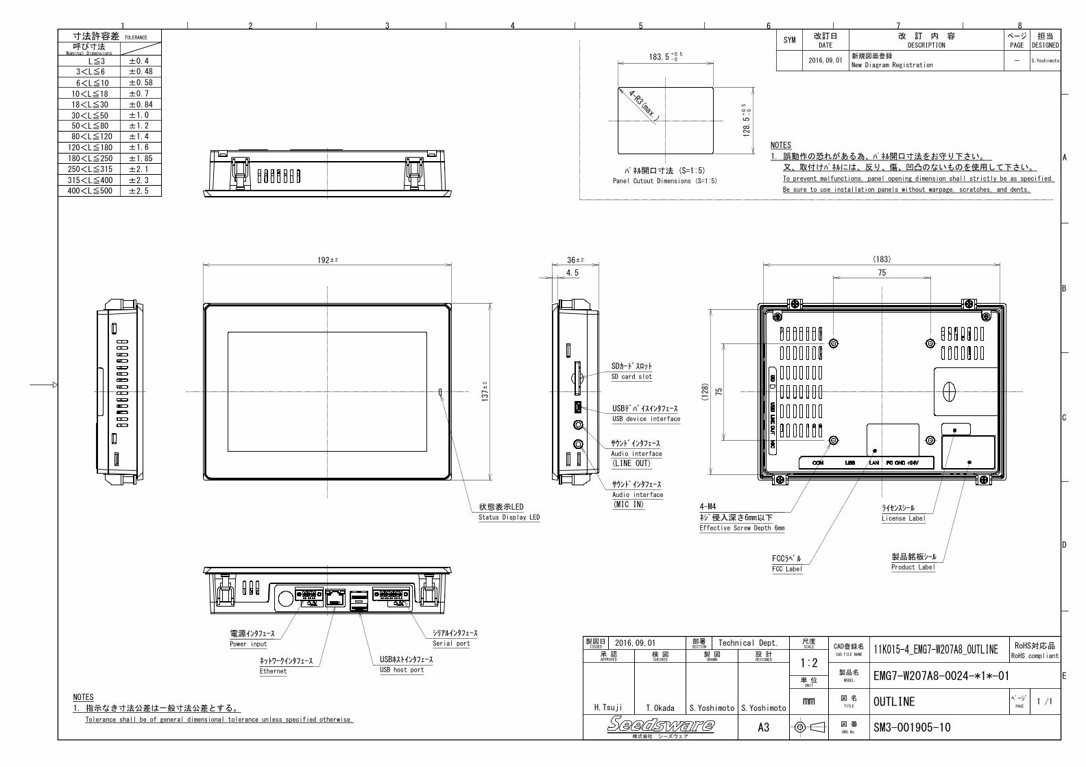
Appendix: Outline drawing (SM3-001905-10)
Page 3
-3- 12A4A2-00007E-8
1. Summary
This specification describes the panel computer with Windows Embedded Compact7.
The panel computer will be referred to as EMG7 hereinafter.
2. Product Model
Specification Model
7” wide Panel computer EMG7-W207A8-0024-011-01
7” wide Panel computer with Indusoft EMG7-W207A8-0024-111-01
3. Packaged Contents
The following items are included in the package:
• EMG7 1 unit
• Mounting Bracket (IS-TK-01) 1 set (4 pcs)
• Battery (SWBT-01) 1 pc
• Protective Sheet (SWCA-7WS00-001) 1 pc
• Gasket (SWPK-7W-01) 1 pc (Pre-installed to unit)
• Power Connector (SWCN-01-03) 1 pc
• Serial Port Connector (SWCN-01-05) 1 pc
• Installation Guide 2 pcs(1 English version and 1 Japanese version.)
• Packaging List 2 pcs(1 English version and 1 Japanese version.)
Page 4
-4- 12A4A2-00007E-8
4. Specification
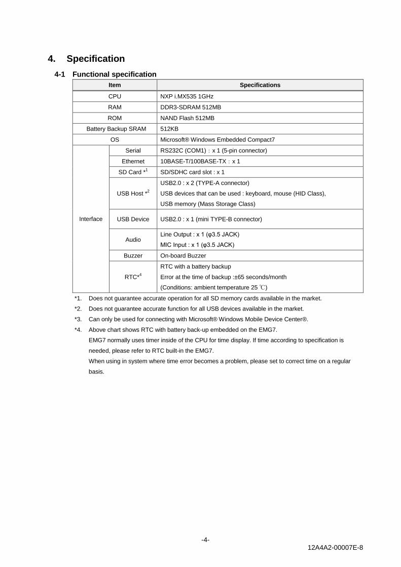
4-1 Functional specification
Item Specifications
CPU NXP i.MX535 1GHz
RAM DDR3-SDRAM 512MB
ROM NAND Flash 512MB
Battery Backup SRAM 512KB
OS Microsoft® Windows Embedded Compact7
Interface
Serial RS232C (COM1):x 1 (5-pin connector)
Ethernet 10BASE-T/100BASE-TX:x 1
SD Card *1 SD/SDHC card slot : x 1
USB Host *2
USB2.0 : x 2 (TYPE-A connector)
USB devices that can be used : keyboard, mouse (HID Class),
USB memory (Mass Storage Class)
USB Device USB2.0 : x 1 (mini TYPE-B connector)
Audio Line Output : x 1 (φ3.5 JACK)
MIC Input : x 1 (φ3.5 JACK)
Buzzer On-board Buzzer
RTC*4
RTC with a battery backup
Error at the time of backup :±65 seconds/month
(Conditions: ambient temperature 25 ℃)
*1. Does not guarantee accurate operation for all SD memory cards available in the market.
*2. Does not guarantee accurate function for all USB devices available in the market.
*3. Can only be used for connecting with Microsoft® Windows Mobile Device Center®.
*4. Above chart shows RTC with battery back-up embedded on the EMG7.
EMG7 normally uses timer inside of the CPU for time display. If time according to specification is
needed, please refer to RTC built-in the EMG7.
When using in system where time error becomes a problem, please set to correct time on a regular
basis.
Page 5
-5- 12A4A2-00007E-8
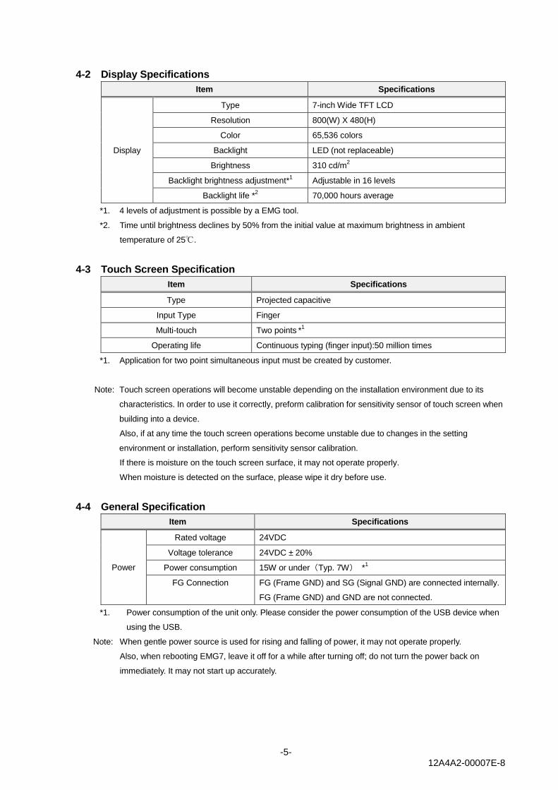
4-2 Display Specifications
Item Specifications
Display
Type 7-inch Wide TFT LCD
Resolution 800(W) X 480(H)
Color 65,536 colors
Backlight LED (not replaceable)
Brightness 310 cd/m2
Backlight brightness adjustment*1 Adjustable in 16 levels
Backlight life *2
70,000 hours average
*1. 4 levels of adjustment is possible by a EMG tool.
*2. Time until brightness declines by 50% from the initial value at maximum brightness in ambient
temperature of 25℃.
4-3 Touch Screen Specification
Item Specifications
Type Projected capacitive
Input Type Finger
Multi-touch Two points *
1
Operating life Continuous typing (finger input):50 million times
*1. Application for two point simultaneous input must be created by customer.
Note: Touch screen operations will become unstable depending on the installation environment due to its
characteristics. In order to use it correctly, preform calibration for sensitivity sensor of touch screen when
building into a device.
Also, if at any time the touch screen operations become unstable due to changes in the setting
environment or installation, perform sensitivity sensor calibration.
If there is moisture on the touch screen surface, it may not operate properly.
When moisture is detected on the surface, please wipe it dry before use.
4-4 General Specification
Item Specifications
Power
Rated voltage 24VDC
Voltage tolerance 24VDC ± 20%
Power consumption 15W or under(Typ. 7W) *1
FG Connection FG (Frame GND) and SG (Signal GND) are connected internally.
FG (Frame GND) and GND are not connected.
*1. Power consumption of the unit only. Please consider the power consumption of the USB device when
using the USB.
Note: When gentle power source is used for rising and falling of power, it may not operate properly.
Also, when rebooting EMG7, leave it off for a while after turning off; do not turn the power back on
immediately. It may not start up accurately.
Page 6
-6- 12A4A2-00007E-8
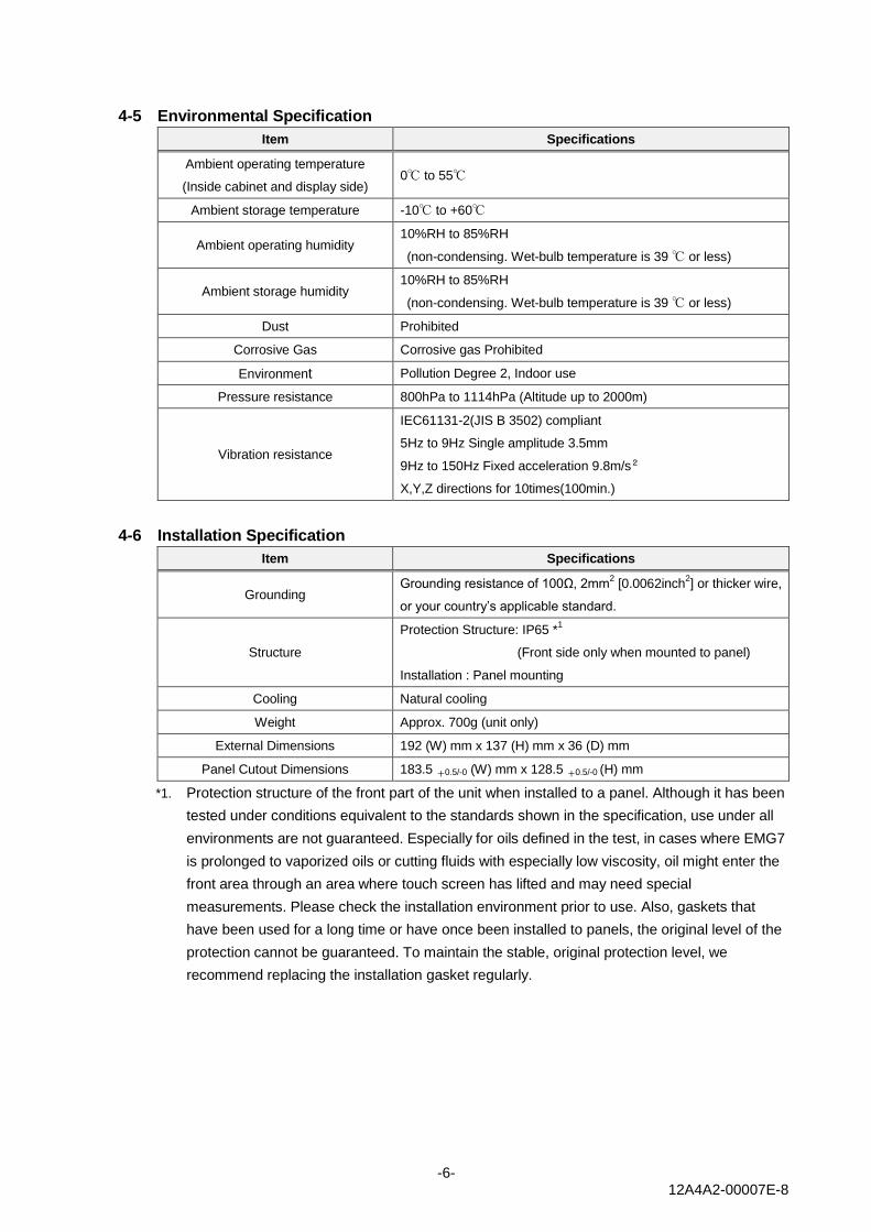
4-5 Environmental Specification
Item Specifications
Ambient operating temperature
(Inside cabinet and display side) 0℃ to 55℃
Ambient storage temperature -10℃ to +60℃
Ambient operating humidity 10%RH to 85%RH
(non-condensing. Wet-bulb temperature is 39 ℃ or less)
Ambient storage humidity 10%RH to 85%RH
(non-condensing. Wet-bulb temperature is 39 ℃ or less)
Dust Prohibited
Corrosive Gas Corrosive gas Prohibited
Environment Pollution Degree 2, Indoor use
Pressure resistance 800hPa to 1114hPa (Altitude up to 2000m)
Vibration resistance
IEC61131-2(JIS B 3502) compliant
5Hz to 9Hz Single amplitude 3.5mm
9Hz to 150Hz Fixed acceleration 9.8m/s2
X,Y,Z directions for 10times(100min.)
4-6 Installation Specification
Item Specifications
Grounding Grounding resistance of 100Ω, 2mm
2 [0.0062inch
2] or thicker wire,
or your country’s applicable standard.
Structure
Protection Structure: IP65 *1
(Front side only when mounted to panel)
Installation : Panel mounting
Cooling Natural cooling
Weight Approx. 700g (unit only)
External Dimensions 192 (W) mm x 137 (H) mm x 36 (D) mm
Panel Cutout Dimensions 183.5 +0.5/-0 (W) mm x 128.5 +0.5/-0 (H) mm
*1. Protection structure of the front part of the unit when installed to a panel. Although it has been
tested under conditions equivalent to the standards shown in the specification, use under all
environments are not guaranteed. Especially for oils defined in the test, in cases where EMG7
is prolonged to vaporized oils or cutting fluids with especially low viscosity, oil might enter the
front area through an area where touch screen has lifted and may need special
measurements. Please check the installation environment prior to use. Also, gaskets that
have been used for a long time or have once been installed to panels, the original level of the
protection cannot be guaranteed. To maintain the stable, original protection level, we
recommend replacing the installation gasket regularly.
Page 7
-7- 12A4A2-00007E-8
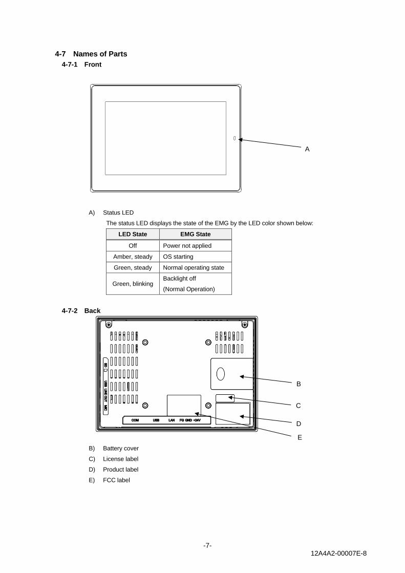
4-7 Names of Parts
4-7-1 Front
A) Status LED
The status LED displays the state of the EMG by the LED color shown below:
LED State EMG State
Off Power not applied
Amber, steady OS starting
Green, steady Normal operating state
Green, blinking Backlight off
(Normal Operation)
4-7-2 Back
B) Battery cover
C) License label
D) Product label
E) FCC label
A
B
C
D
E
Page 8
-8- 12A4A2-00007E-8
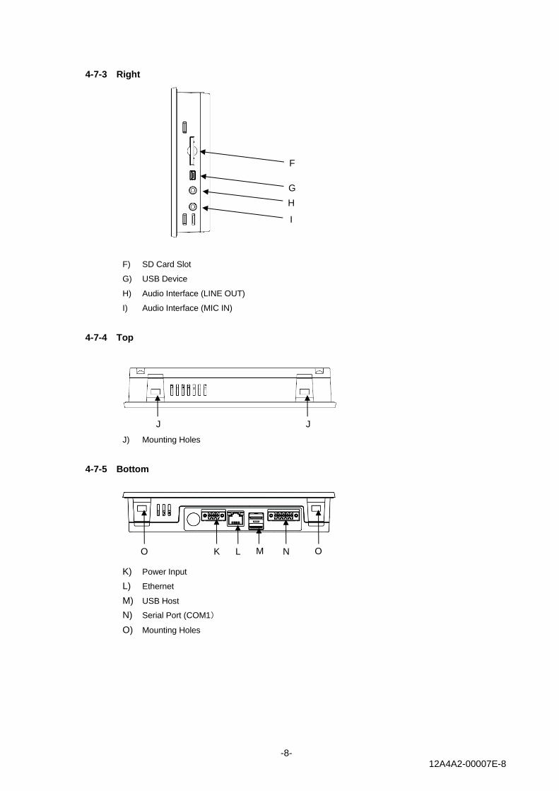
4-7-3 Right
F) SD Card Slot
G) USB Device
H) Audio Interface (LINE OUT)
I) Audio Interface (MIC IN)
4-7-4 Top
J) Mounting Holes
4-7-5 Bottom
K) Power Input
L) Ethernet
M) USB Host
N) Serial Port (COM1)
O) Mounting Holes
F
G
H
I
J J
K
L
n
M
N
O
O
Page 9
-9- 12A4A2-00007E-8
4-8 External Interface
4-8-1 SD Card Slot
Connector : SD / SDHC memory card (Push-in/push-out method)
Corresponding media : SD/SDHC memory card
Maximum capacity : 32GB
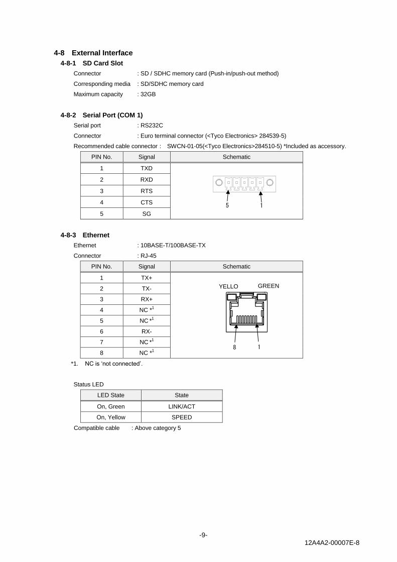
4-8-2 Serial Port (COM 1)
Serial port : RS232C
Connector : Euro terminal connector (<Tyco Electronics> 284539-5)
Recommended cable connector : SWCN-01-05(<Tyco Electronics>284510-5) *Included as accessory.
PIN No. Signal Schematic
1 TXD
2 RXD
3 RTS
4 CTS
5 SG
4-8-3 Ethernet
Ethernet : 10BASE-T/100BASE-TX
Connector : RJ-45
PIN No. Signal Schematic
1 TX+
2 TX-
3 RX+
4 NC *1
5 NC *
1
6 RX-
7 NC *
1
8 NC *1
*1. NC is ‘not connected’.
Status LED
LED State State
On, Green LINK/ACT
On, Yellow SPEED
Compatible cable : Above category 5
1 5
8 1
GREEN YELLO
W
Page 10
-10- 12A4A2-00007E-8
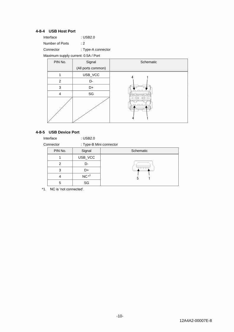
4-8-4 USB Host Port
Interface : USB2.0
Number of Ports : 2
Connector : Type-A connector
Maximum supply current: 0.5A / Port
PIN No. Signal
(All ports common)
Schematic
1 USB_VCC 2 D-
3 D+
4 SG
4-8-5 USB Device Port
Interface : USB2.0
Connector : Type-B Mini connector
PIN No. Signal Schematic
1 USB_VCC
2 D-
3 D+
4 NC *
1
5 SG
*1. NC is ‘not connected’.
1 5
1 4
1 4
Page 11
-11- 12A4A2-00007E-8
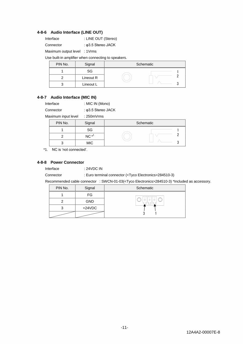
4-8-6 Audio Interface (LINE OUT)
Interface : LINE OUT (Stereo)
Connector : φ3.5 Stereo JACK
Maximum output level : 1Vrms
Use built-in amplifier when connecting to speakers.
PIN No. Signal Schematic
1 SG
2 Lineout R
3 Lineout L
4-8-7 Audio Interface (MIC IN)
Interface : MIC IN (Mono)
Connector : φ3.5 Stereo JACK
Maximum input level : 250mVrms
PIN No. Signal Schematic
1 SG
2 NC *
1
3 MIC
*1. NC is ‘not connected’.
4-8-8 Power Connector
Interface : 24VDC IN
Connector : Euro terminal connector (<Tyco Electronics>284510-3)
Recommended cable connector : SWCN-01-03(<Tyco Electronics>284510-3) *Included as accessory.
PIN No. Signal Schematic
1 FG
2 GND
3 +24VDC
1 2
3
1
2
3
1 3
Page 12
-12- 12A4A2-00007E-8
4-9 Software Specification
The EMG7 is installed with Windows® Embedded Compact 7.
Specification for Windows ®Embedded Compact 7 of Microsoft ® will follow that of Microsoft ®.
4-9-1 Application Software Development Environment
Below tools can be used for application software development.
・Microsoft® Visual Studio®.NET 2008*1
*1. SDK (provided) must be built into above listed tools when developing applications.
Microsoft® Windows Mobile Device Center can be used with USB device port of EMG7.
USB client can be can be used as communication port.
Page 13
-13- 12A4A2-00007E-8
5. Installation
5-1 Installing Condition
• When mounting the EMG7 to panels, be sure to have enough room for inserting and removing SD cards,
cables, and mounting brackets.
• Be sure that the ambient operation temperature (0℃ to 55℃) and the ambient humidity (10%RH to 85%RH.
Wet-bulb temperature is 39 ℃ or less) )are within their designated ranges.
• “Ambient operation temperature” indicates both the display side and inside of cabinet where the EMG7 will be
installed.
・ EMG7 should be mounted perpendicular, but if it should be mounted in an angle, the angle shall not be more
than 30degrees from the vertical position shown in the illustration below:
・ When installing the EMG7 in a slanted panel of angle 30 degrees or more, please use forced air cooling to
ensure the temperature specification.
Inside cabinet Display side
30°or less
Page 14
-14- 12A4A2-00007E-8
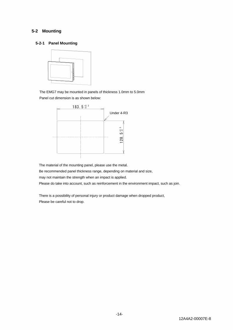
5-2 Mounting
5-2-1 Panel Mounting
The EMG7 may be mounted in panels of thickness 1.0mm to 5.0mm
Panel cut dimension is as shown below:
The material of the mounting panel, please use the metal.
Be recommended panel thickness range, depending on material and size,
may not maintain the strength when an impact is applied.
Please do take into account, such as reinforcement in the environment impact, such as join.
There is a possibility of personal injury or product damage when dropped product,
Please be careful not to drop.
-0+0 .5183.5
128.5
-0
+0.5
4-R3以下Under 4-R3
Page 15
-15- 12A4A2-00007E-8
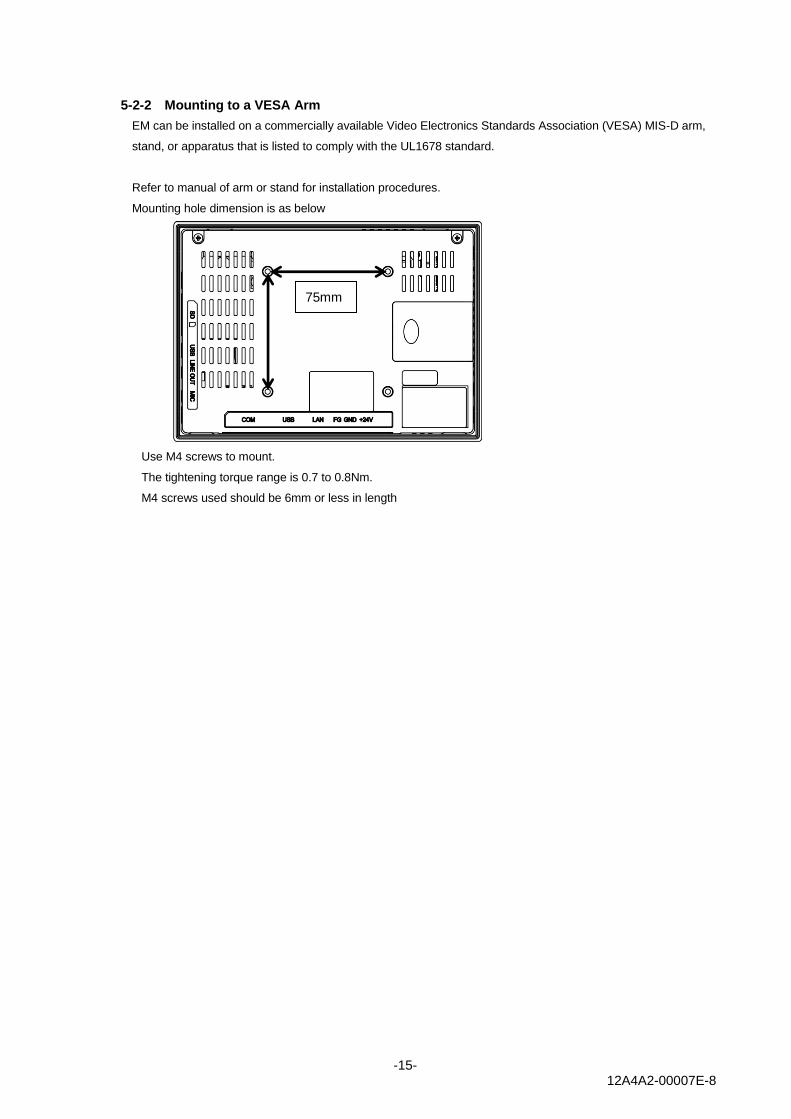
5-2-2 Mounting to a VESA Arm
EM can be installed on a commercially available Video Electronics Standards Association (VESA) MIS-D arm,
stand, or apparatus that is listed to comply with the UL1678 standard.
Refer to manual of arm or stand for installation procedures.
Mounting hole dimension is as below
Use M4 screws to mount.
The tightening torque range is 0.7 to 0.8Nm.
M4 screws used should be 6mm or less in length
75mm
Page 16
-16- 12A4A2-00007E-8
6. Compatible Standards
EMG is intended for use in industrial environments and, when properly installed, shall comply with the
following agency approvals.
6-1 UL Standard
This product is UL standard compliant
UL standard No. UL Registration Model No. UL File No.
UL 61010-1 / UL 61010-2-201
CSA C22.2 No 142–M1987;
G-0001UA E464360
6-2 CE Marking
This product is EMC Directive of EU compliant
Complying standard : EMI:EN 61000-6-4:2007+AI:2011
EMS:EN 61000-6-2:2005
6-3 RoHS Directives
This product is RoHS Directive of EU complaint.
6-4 FCC
The FCC requires the following note to be published according to FCC guidelines:
Note:
This equipment has been tested and found to comply with the limits for a Class A digital device, pursuant to Part
15 of the FCC Rules. These limits are designed to provide reasonable protection against harmful interference
when the equipment is operated in a commercial environment. This equipment generates, uses, and can radiate
radio frequency energy and, if not installed and used in accordance with the instruction manual, may cause
harmful interference to radio communications. Operation of this equipment in a residential area is likely to cause
harmful interference in which case the user is required to correct the interference at their own expense.
Changes or modifications to this unit that are not expressly approved by Seedsware could void the user’s
authority to operate the equipment.
Industry Canada requires the following note to be published:
Note:
This Class A digital apparatus complies with Canadian CAN ICES-3 (A)/NMB-3 (A).
Page 17
-17- 12A4A2-00007E-8
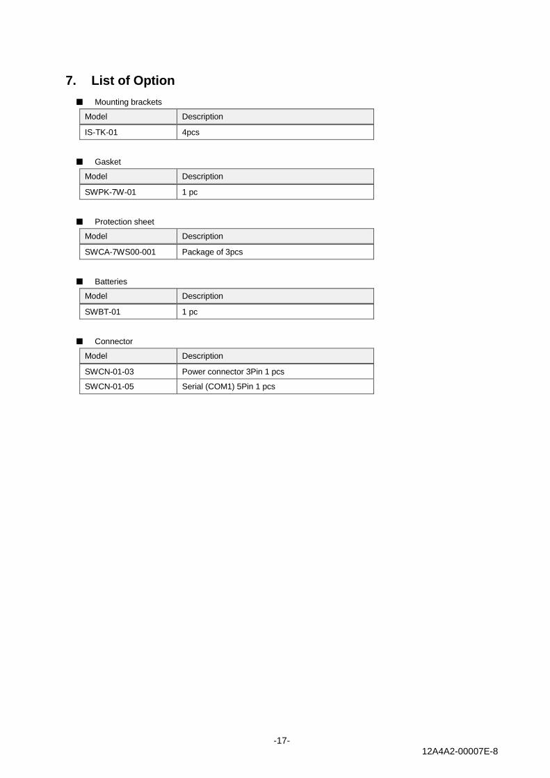
7. List of Option
■ Mounting brackets
Model Description
IS-TK-01 4pcs
■ Gasket
Model Description
SWPK-7W-01 1 pc
■ Protection sheet
Model Description
SWCA-7WS00-001 Package of 3pcs
■ Batteries
Model Description
SWBT-01 1 pc
■ Connector
Model Description
SWCN-01-03 Power connector 3Pin 1 pcs
SWCN-01-05 Serial (COM1) 5Pin 1 pcs
Page 18
-18- 12A4A2-00007E-8
8. Warranty
8-1 Warranty Period
The warranty period is limited to12 months (1 year) from the date of shipment. Warranty for any repair needed to
the same repaired part of the same product is three months. Any defects that occur upon normal use under
conditions specified herein will be repaired (factory repair) free of charge.
Any defected parts under proper use will be examined by the supplier and replaced by the new parts if the defect is
considered to be caused by the supplier.
The replacement is subject to be included in the next lot.
8-2 Warranty Exceptions
You will be liable for all repair fees even within the warranty period for any conditions listed below:
(1) Any malfunctions, defects, and/or damages that occurred during transport, transfer, or mishandling by the
user after delivery
(2) Any malfunctions, defects, and/or damages caused by natural or man-made disaster.
(3) Any malfunctions and damages caused by static electricity.
(4) If the product is used under any condition, in any environment, or by any method other than those specified in
the specifications, catalogs, manuals, notes, and/or other documents.
(5) Any replacement of consumables.
(6) Any malfunctions, defects, and/or damages caused by associated equipment and/or usage of inappropriate
consumables and media.
(7) If the product is repaired, remodeled, modified, or disassembled by a party other than Seedsware
(8) If the product cannot be identified by a serial number.
(9) Any malfunctions, defects, and/or damages that are to have been caused on your behalf.
This warranty covers only the product itself. Any damages, on-site repairs and replacement driven by the
failure of the product will be decided upon discussion by both parties as necessary.
This product is structurally not repairable. All damaged parts are subject for replacement and freight will be
charged.
9. Production Discontinuance
In the event of product discontinuance, an announcement will be made on our website six months prior to the last
possible order reception date.
Page 19
-19- 12A4A2-00007E-8
10. Others
For comments or queries, feel free to contact us via e-mail or phone.
By Phone
+1-630-832-0438 (Business Hours: 9:00a.m. ~5:45p.m. CT)
By E-mail
[email protected]
FAQ
www.seedsware.co.jp/global/support/faq/
Microsoft®, Windows® Embedded Compact7, Windows Mobile Device Center®, Visual Studio.NET 2008®, are
registered trademarks of Microsoft Corporation in the United States and other countries.
8th Edition October, 2016
USCO America Inc.
136 W. Valletts Street, Elmhurst, IL 60126 USA
Phone: 630-832-0438/510-931-9046
E-mail: [email protected]
Business hours: 9:00a.m.~5:45p.m. (Central Time)
http://uscoamerica.com/
This document is protected by copyright law. Photocopying, duplicating, reproducing, and modifying of this product or
document in part or by whole is prohibited.
Page 20
1 2 3 4 5 6 7 8
A
B
C
D
E
製図日
ISSUED
製 図
DRAWN
承 認
APPROVED
検 図
CHECKED
設 計
DESIGNED
部署
SECTION
尺度
SCALE
Technical Dept.
図 名
TITLE
単 位
UNIT
mm
製品名
MODEL
CAD登録名
CAD FILE NAME
図 番
DWG No.
A3
EMG7-W207A8-0024-*1*-01
OUTLINE
11K015-4_EMG7-W207A8_OUTLINE
株式会社 シーズウェア
ページ
PAGE
1 /1
2016,09,01
SM3-001905-10
1:2
RoHS対応品
RoHS compliant
S.YoshimotoS.YoshimotoT.OkadaH.Tsuji
パネル開口寸法 (S=1:5)
Panel Cutout Dimensions (S=1:5)
SYM
改訂日
DATE
2016,09,01
新規図面登録
New Diagram Registration
DESCRIPTION
改 訂 内 容
PAGE
ページ 担当
DESIGNED
- S.Yoshimoto
183.5- 0
0.5+
128.5
-00.5
+
R
3
4
-
(
m
a
x
.
)
NOTES
1. 誤動作の恐れがある為、パネル開口寸法をお守り下さい。
又、取付けパネルには、反り、傷、凹凸のないものを使用して下さい。
To prevent malfunctions, panel opening dimension shall strictly be as specified.
Be sure to use installation panels without warpage, scratches, and dents.
192`2
137`2
4.5
36`2
75
(128)
75
(183)
4-M4
ネジ侵入深さ6mm以下
Effective Screw Depth 6mm
FCCラベル
FCC Label
製品銘板シール
Product Label
寸法許容差 TOLERANCE
呼び寸法
Nominal Dimensions
L≦3
10<L≦18
18<L≦30
6<L≦10
30<L≦50
±0.4
±0.58
±0.7
±0.84
±1.0
±0.483<L≦6
50<L≦80
80<L≦120
120<L≦180
180<L≦250
250<L≦315
315<L≦400
400<L≦500
±1.2
±1.4
±1.6
±1.85
±2.1
±2.3
±2.5
NOTES
1. 指示なき寸法公差は一般寸法公差とする。
Tolerance shall be of general dimensional tolerance unless specified otherwise.
SDカードスロット
SD card slot
USBデバイスインタフェース
USB device interface
サウンドインタフェース
Audio interface
(LINE OUT)
サウンドインタフェース
Audio interface
(MIC IN)
電源インタフェース
Power input
ネットワークインタフェース
Ethernet
USBホストインタフェース
USB host port
シリアルインタフェース
Serial port
状態表示LED
Status Display LED
ライセンスシール
License Label