96

CE COMPLIANCE INFORMATION (FOR EUROPEAN MARKET)
EMC Directive 89/336/EEC and Amendment 92/31/EEC, Class B Digital Device.EN 50081-1, Generic Emissions Standard for Residential, Commercial and Light Industrial Products.(EN 55022/CISPR 22, Limits and Methods of Measurement of Radio Interference Characteristics Information Technology Equipment.) Warning: This is a Class Bproduct. In a domestic environment this product may cause radio interference in which case the user may be required to take adequate measures.EN 50082-1, Generic Immunity Standard for Residential, Commerical and Light Industrial Products.(IEC 801-2, IEC 801-3, IEC 801-4)
Directive EMC 89/336/CEE et amendement 92/31/CEE, dispositif numérique de Classe B.EN 50081-1, Norme sur les émissions génériques pour les produits domestiques, commerciaux et industriels légers.(EN 55022/CISPR 22, Limites et méthodes de mesure des caractéristiques d’interférences radiophoniques, Matériel des technologies de l’information.) Mise engarde: ceci est un produit de Classe B. Il risque produire des interférences radiophoniques dans un environnement domestique auquel cas l’utilisateur peut sevoir demandé de prendre des mesures adéquates.EN 50082-1, Norme sur l’immunité générique pour produits domestiques, commerciaux et industriels légers.(CEI 801-2, CEI 801-3, CEI 801-4)
EMC Richtlinie 89/336/EEC und Änderung 92/31/EEC, Digitales Gerät der Klasse B.EN 50081-1, Allgemeiner Emissions - Standard für Haushalt - und kommerzielle Produkte sowie Erzeugnisse der Leichtindustrie.(EN 55022/CISPR 22, Beschränkungen und Verfahren der Messung von informationstechnischen Ausrüstungen mit Funkstörmerkmalen.)Warnung: Dies ist ein Erzeugnis der Klasse B. Dieses Erzeugnis kann Funkstörungen im Wohnbereich verursachen; in diesem Fall können entsprechendeMaßnahmen seitens des Benutzers erforderlich sein.EN 50082-1, Allgemeiner Unempfindlichkeits - Standard fur Haushalt - und kommerzielle Produkte sowie Erzeugnisse der Leichtindustrie.(IEC 801-2, IEC 801-3, IEC 801-4)

© 2002 Lexicon, Inc. All rights reserved.
This document should not be construed as a commitment on the part of Lexicon, Inc. The information it contains is subject to changewithout notice. Lexicon, Inc. assumes no responsibility for errors that may appear within this document.
A Harman International Company
Lexicon, Inc.3 Oak ParkBedford, MA 01730-1441 USATel 781-280-0300Fax 781-280-0490www.lexicon.com
Customer SupportTel 781-280-0300Fax 781-280-0495 (Sales)Fax 781-280-0499 (Service)
Lexicon Part No. 070-14956 | Rev 1 | 02/02
This equipment has been tested and found to comply with the limits for a Class B digital device, pursuant to Part 15 of the FCC Rules. Theselimits are designed to provide reasonable protection against harmful interference in a residential installation. This equipment generates, uses andcan radiate radio frequency energy and, if not installed and used in accordance with manufacturer’s instructions, may cause harmful interferenceto radio communications. However, there is no guarantee that interference will not occur in a particular installation. If this equipment does causeharmful interference to radio or television reception, which can be determined by turning the equipment off and on, the user is encouraged to tryto correct the interference by one or more of the following measures:
1. Re-orient the receiving antenna.2. Increase the separation between the equipment and receiver.3. Connect the equipment to an outlet on a circuit different from that to which the receiver is connected,.4. Consult the dealer or an experienced radio/TV technician for help.
• The use of shielded cables for connection of the monitor to the graphics card is required to ensure compliance with FCC regulations.• Changes or modifications to this unit not expressly approved by the party responsible for compliance could void the user’s authority to operate
this equipment.

Introduction Lexicon
ii
Introduction
Important User Information. . . . . . . . . . . . . . iv
Wichtige Benutzerinformation . . . . . . . . . . . . v
Información importante para el usuario . . . . . vi
Important - Informations Utilisateur . . . . . . . vii
Importanti informazioni per l’utente. . . . . . . viii
Informações Importantes ao usuário . . . . . . . ix
Section 1: Getting Started
About the MPX 110 . . . . . . . . . . . . . . . . . . . . . . . . 1-2Highlights
Front Panel Overview . . . . . . . . . . . . . . . . . . . . . . . 1-4
Rear Panel Overview . . . . . . . . . . . . . . . . . . . . . . . 1-6
Connecting the Unit . . . . . . . . . . . . . . . . . . . . . . . 1-8Headphones • Footswitch
Setting Audio Levels . . . . . . . . . . . . . . . . . . . . . . . 1-10
Reinitialization . . . . . . . . . . . . . . . . . . . . . . . . . . . 1-11
Section 2: Basic Operation
Adjust . . . . . . . . . . . . . . . . . . . . . . . . . . . . . . . . . . 2-2
Selecting Programs . . . . . . . . . . . . . . . . . . . . . . . . 2-2SINGLE Programs • DUAL Programs • User Programs
Editing Programs . . . . . . . . . . . . . . . . . . . . . . . . . . 2-4
Storing Programs . . . . . . . . . . . . . . . . . . . . . . . . . . 2-4
Tap Tempo . . . . . . . . . . . . . . . . . . . . . . . . . . . . . . 2-5Varying Rhythm • Audio Tap • Global Tempo
Bypass. . . . . . . . . . . . . . . . . . . . . . . . . . . . . . . . . . 2-6
FR
IT
PT
ES
DE
US

IntroductionMPX 110
iii
Section 3: System Mode
Overview. . . . . . . . . . . . . . . . . . . . . . . . . . . . . . . . 3-2
System Mode Parameters & Functions . . . . . . . . . . 3-3
Section 4: Program Descriptions
SINGLE Programs. . . . . . . . . . . . . . . . . . . . . . . . . . 4-2Plate • Gate • Hall • Chamber • Ambience • Room • Tremolo •Rotary • Chorus • Flange • Pitch • Detune • Delay, Echo
Special FX . . . . . . . . . . . . . . . . . . . . . . . . . . . . . . 4-18
DUAL Programs . . . . . . . . . . . . . . . . . . . . . . . . . . 4-20Effects Lvl/Bal • Flange-Delay • Pitch-Delay • Chorus-Delay •Delay-Reverb • Flange-Reverb • Pitch-Reverb • Chorus-Reverb
The Pitch Programs . . . . . . . . . . . . . . . . . . . . . . . 4-36
User Programs . . . . . . . . . . . . . . . . . . . . . . . . . . . 4-38
Section 5: MIDI Operation
Learn Mode. . . . . . . . . . . . . . . . . . . . . . . . . . . . . . 5-2
Program Load Channel. . . . . . . . . . . . . . . . . . . . . . 5-3
Program Change Messages . . . . . . . . . . . . . . . . . . 5-4Loading Programs • Activating Bypass or Tap Functions
Learning Continuous Controllers. . . . . . . . . . . . . . . 5-6
Section 5: MIDI Operation (continued)
Clearing Learned Assignments . . . . . . . . . . . . . . . . 5-7
MIDI Clock . . . . . . . . . . . . . . . . . . . . . . . . . . . . . . 5-8
MIDI Dumps . . . . . . . . . . . . . . . . . . . . . . . . . . . . . 5-8
MIDI Sysex Messages . . . . . . . . . . . . . . . . . . . . . . . 5-9
Permanent Patches . . . . . . . . . . . . . . . . . . . . . . . . 5-9
MIDI Implementation Chart . . . . . . . . . . . . . . . . . 5-12
Appendix
Specifications. . . . . . . . . . . . . . . . . . . . . . . . . . . . . A-2
Declaration of Conformity . . . . . . . . . . . . . . . . . . . A-3
Index
Introduction Lexicon
iv
Important User InformationLexicon is pleased to present its user guides on CD-ROM.By utilizing CD-ROM technology we are able to provideour documentation in multiple languages.
The printed edition of the user guide is in English only.The enclosed CD-ROM includes the user guide inmultiple languages (French, German, Italian, Portuguese,and Spanish) in easy-to-use PDF format. The CD-ROMalso includes Adobe® Acrobat® Readers for both PC andMacintosh platforms, enabling printing of all or any partof the documents. In addition, we have included dryaudio tracks for product demonstrations. (Track 1contains non-audio data.)
Please take a moment to read through the importantsafety information. For additional information aboutLexicon, Inc., our products and support, please visit ourweb site at www.lexicon.com.
Unpacking and InspectionAfter unpacking the unit, save all packing materials incase the unit ever needs to be shipped. Thoroughlyinspect the modules and packing materials for signs ofdamage. Report any damage to the carrier at once;report equipment malfunction to the dealer.
US
IntroductionMPX 110
v
Wichtige BenutzerinformationLexicon ist erfreut, seine Benutzerhandbücher nun auchauf CD-ROM vorlegen zu können. Durch den Einsatz vonCD-ROM-Technologie können wir unsere Dokumentationin verschiedenen Sprachen zur Verfügung stellen.
Die gedruckte Ausgabe des Benutzerhandbuchs ist nur inenglischer Sprache verfügbar. Die beigelegte CD-ROMenthält das Benutzerhandbuch in verschiedenenSprachen (spanisch, französisch, italienisch, deutsch undportugiesisch) im leicht zu benutzenden PDF-Format.Die CD-ROM enthält auch Adobe® Acrobat® Readersowohl für PC wie auch für Macintosh; mit ihm ist esmöglich, das gesamte Dokument oder Teile davonauszudrucken. Darüber hinaus befinden sich auf derCD-ROM Audio-Tracks zur Produktdemonstration.(Track 1 enthält keine Audio-Daten.)
Nehmen Sie sich bitte einen Augenblick Zeit und lesenSie die wichtigen Sicherheitshinweise. WeitereInformationen über Lexicon, Inc., sowie über unsereProdukte und unseren Support finden Sie auf unseremWebsite unter www.lexicon.com.
Auspacken und ÜberprüfungBewahren Sie nach dem Auspacken des Geräts dasVerpackungsmaterial für den Fall auf, dass Sie das Gerätwieder versenden müssen. Überprüfen Sie die Moduleund die Verpackung sorgfältig auf Anzeichen vonBeschädigung. Etwaige Schäden sind dem Transporteurunverzüglich anzuzeigen; Funktionsstörungen sind demzuständigen Händler zu melden.
DE
Introduction Lexicon
vi
Información importante para elusuario
Lexicon se complace en presentar sus manuales deusuario en CD-ROM. Gracias a la utilización de latecnología de CD-ROM, nosotros podemos ofrecer nues-tra documentación en múltiples idiomas.
La edición impresa del manual del usuario sólo estádisponible en inglés. El CD-ROM que se entrega incluyeel manual del usuario en múltiples idiomas (español,francés, italiano, alemán y portugués) en formato PDF. ElCD-ROM también incluye Adobe® Acrobat® Readerspara plataformas tanto PC como Macintosh, lo cualpermite la impresión de todos o parte de losdocumentos. Además, hemos incluido pistas de audiosin efectos para demostraciones de los productos. (Lapista 1 contiene información que no es de audio.)
Dedique unos momentos a leer la información deseguridad importante. Si desea información adicionalacerca de Lexicon, Inc., nuestros productos o nuestraasistencia, visite nuestro sitio web en www.lexicon.com.
Desembalaje e inspecciónDespués de desembalar la unidad, guarde todos losmateriales de embalaje por si alguna vez transportar launidad. Inspeccione con atención los módulos y losmateriales de embalaje para comprobar que nomuestren desperfectos. Informe inmediatamente decualquier desperfecto al transportista; informe decualquier problema de funcionamiento del equipo a sudistribuidor.
ES

IntroductionMPX 110
vii
Important - Informations UtilisateurNous sommes fiers de présenter nos modes d’emploi enversion CD-ROM. L’utilisation des CD-ROM nousper-mettent de décliner nos manuels en plusieurslangues.
La version imprimée de ce manuel existe uniquement enanglais. Le CD-ROM regroupe les versions espagnole,française, italienne, allemande et portugaise au formatPDF. Le CD-ROM comprend également Adobe®Acrobat® Reader pour PC et Macintosh, ce qui vouspermet d’imprimer les documents en toute ou partie. Deplus, nous avons ajouté des pistes audio sans traitementpour la démonstration du produit (la piste 1 contient desdonnées non audio).
Prenez le temps de lire les informations relatives à lasécurité. Pour obtenir de plus amples informations surLexicon, Inc., nos produits et notre service clientèle,consultez notre site web à l’adresse : www.lexicon.com.
Contenu de l’emballage et inspectionAprès avoir ouvert l’emballage, conservez-le pour toutretour. Inspectez avec soin les modules et les matériauxd’emballage pour tout signe de dommage. Veuillezrapporter immédiatement les dommages auprès dutransporteur. Les dysfonctionnements du matérieldoivent être signalés à votre revendeur.
FR
Introduction Lexicon
viii
Importanti informazioni per l’utenteLexicon è lieta di presentare i propri manuali su CD-ROM. Utilizzando la tecnologia su CD-ROM siamo staticapaci offrire la nostra documentazione in più lingue.
L’edizione stampata del manuale è solamente in inglese.Il CD-ROM contiene il manuale in diverse lingue(Spagnolo, Francese, Italiano, Tedesco, e Portoghese)informato PDF, facile da utilizzare. Il CD-ROM includeanche Adobe‚, Acrobat‚ Reader per PC e per Macintosh,rendendo possibile la stampa di tutta ladocumentazione. Inoltre Sono incluse tracce audio perdimostrazioni del prodotto. (La Traccia 1 contiene datinon audio).
Si prega di prendere un momento per leggere leimportanti norme di sicurezza. Per ulteriori informazioniriguardo Lexicon, Inc., i nostri prodotti e la nostraassistenza, visiti il nostro sito internet www.lexicon.com.
Disimballaggio ed ispezioneDopo aver disimballato l’unità, salvi tutto il materialed’imballaggio, in caso Lei abbia bisogno di spedirel’unità. Ispezioni attentamente i moduli ed il materialed’imballaggio per vedere se riportano segni di danno.Riporti subito ogni segno di danno al corriere; riferisca ilmalfunzionamento dell’attrezzatura al suo rivenditore.
IT

IntroductionMPX 110
ix
Informações Importantes ao usuárioA Lexicon tem o prazer de apresentar o Guia do Usuárioem CD-ROM. Através da tecnologia CD-ROM temos apossibilidade de fornecer nossa documentação em váriosidiomas.
A versão impressa do Guia do Usuário está apenas emInglês. O CD-ROM contém o Guia do Usuário em váriosidiomas (Espanhol, Francês, Italiano, Alemão ePortuguês) em formato PDF. Também inclui o aplicativoAdobe Acrobat Reader para as plataformas Macintosh ePC, possibilitanto a impressão de qualquer parte dadocumentação. Além disso, incluimos faixas no CD comáudio sem processamento para a demosntração dosprodutos. (A faixa 1 do CD não contém informação deáudio.)
Por favor separe uns instantes para ler as informaçõessobre segurança. Elas são muito importantes. Parainformações adicionais sobre a Lexicon, Inc., nossosprodutos e suporte, acesse nosso web site emwww.lexicon.com.
Retirando a embalagem e InspecionandoDepois de desembalar a unidade, guarde a embalagemcaso precise enviar a unidade para manutenção.Inspecione cuidadosamente o módulo e a embalagemprocurando sinais de dano. Avise à loja qualquer tipo dedano ou mal funcionamento do equipamento.
PT

Getting Started
1About the MPX 110.........................................................................1-2
Highlights
Front Panel Overview ......................................................................1-4
Rear Panel Overview........................................................................1-6
Connecting the Unit........................................................................1-8Headphones • Footswitch
Setting Audio Levels ......................................................................1-10
Reinitialization ...............................................................................1-11
Getting Started Lexicon
1-2
ABOUT THE MPX 110Thank you for purchasing the MPX 110 Dual ChannelProcessor, featuring Lexicon’s proprietary Lexichip®.
The MPX 110 is a true stereo, dual-channel processorwith 24-bit internal processing, analog-to-digitalconversion, and digital-to-analog conversion. It offers240 presets with classic Lexicon reverbs, including Plate,Chamber, Ambience, Tremolo, Rotary, Chorus, Flange,Pitch, Detune, 5.7 second Delay, Echo, and Inverse.Dual-channel processing creates two independenteffects in combinations such as Dual Stereo (Parallel),Cascade, Mono Split, and Dual Mono.
The front panel Adjust knob allows instant manipulationof critical preset parameters, and the Effects Lvl/Bal knobcontrols effect level in SINGLE programs or effectbalance in DUAL programs. All programs can be selectedwith the PROGRAM and VARIATION knobs. ThePROGRAM knob selects SINGLE, DUAL, or Userprograms, while the VARIATION knob selects among 16program variations.
Tap Tempo simplifies the once-complicated process ofmatching delay times and modulation rates betweentempo-based presets and other music. Tempo-controlleddelays and modulation rates lock to Tap or MIDI clock. Inaddition, Tap can be controlled using audio input, a dualfootswitch, the front panel Tap button, or an externalMIDI controller using MIDI Continuous Controller orProgram Change messages.
The MPX 110 features Learn Mode, a powerful editingtool that allows MIDI patching of five front panelcontrols. Standard Continuous Controller and ProgramChange messages provide complete control over Bypass,Effects Lvl/Bal, Mix, Tap, and even Adjust.
Getting StartedMPX 110
1-3
HIGHLIGHTS• Lexicon’s proprietary Lexichip
• World-class Lexicon reverb
• 24-bit internal processing
• 24-bit analog-to-digital and digital-to-analogconversion
• 240 presets
• 16 User programs
• 44.1K S/PDIF output
• Simultaneous analog and digital outputs
• Independent processing of each input
• DUAL programs that create two independent effectswith four routing configurations
• Dual effects that combine Delay with Reverb, oreither Delay or Reverb with Chorus, Flange, or Pitch
• Multiple delay, modulation, and pitch effects
• Tap Tempo
• Full MIDI control
• High-impedance inputs for instruments
• Two-stage headroom indicators
• Headphone output
• Software-selectable MIDI OUT/THRU port
• Push-button or footswitch selection of dry or mutedaudio output
• 20Hz-20kHz±1dB frequency response
Getting Started Lexicon
1-4
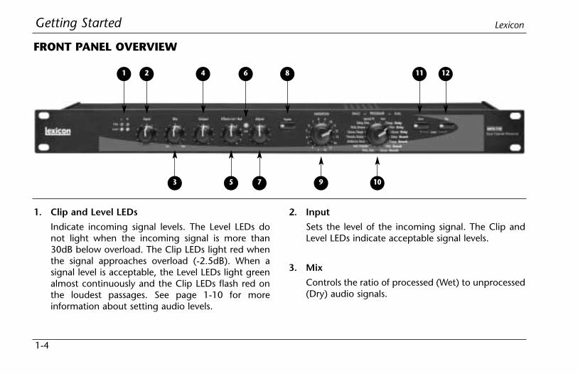
1. Clip and Level LEDs
Indicate incoming signal levels. The Level LEDs donot light when the incoming signal is more than30dB below overload. The Clip LEDs light red whenthe signal approaches overload (-2.5dB). When asignal level is acceptable, the Level LEDs light greenalmost continuously and the Clip LEDs flash red onthe loudest passages. See page 1-10 for moreinformation about setting audio levels.
2. Input
Sets the level of the incoming signal. The Clip andLevel LEDs indicate acceptable signal levels.
3. Mix
Controls the ratio of processed (Wet) to unprocessed(Dry) audio signals.
FRONT PANEL OVERVIEW
1 2
3 5 7 9 10
4 6 8 11 12
Getting StartedMPX 110
1-5
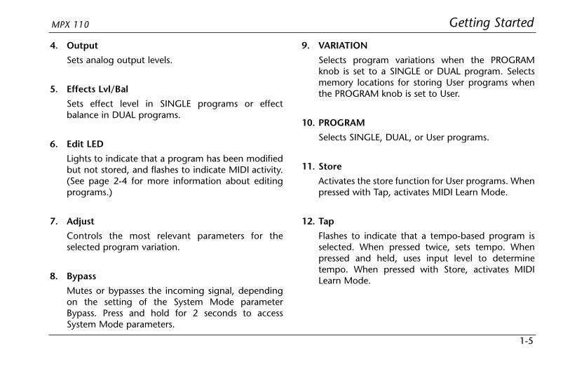
4. Output
Sets analog output levels.
5. Effects Lvl/Bal
Sets effect level in SINGLE programs or effectbalance in DUAL programs.
6. Edit LED
Lights to indicate that a program has been modifiedbut not stored, and flashes to indicate MIDI activity.(See page 2-4 for more information about editingprograms.)
7. Adjust
Controls the most relevant parameters for theselected program variation.
8. Bypass
Mutes or bypasses the incoming signal, dependingon the setting of the System Mode parameterBypass. Press and hold for 2 seconds to accessSystem Mode parameters.
9. VARIATION
Selects program variations when the PROGRAMknob is set to a SINGLE or DUAL program. Selectsmemory locations for storing User programs whenthe PROGRAM knob is set to User.
10. PROGRAM
Selects SINGLE, DUAL, or User programs.
11. Store
Activates the store function for User programs. Whenpressed with Tap, activates MIDI Learn Mode.
12. Tap
Flashes to indicate that a tempo-based program isselected. When pressed twice, sets tempo. Whenpressed and held, uses input level to determinetempo. When pressed with Store, activates MIDILearn Mode.
Getting Started Lexicon
1-6
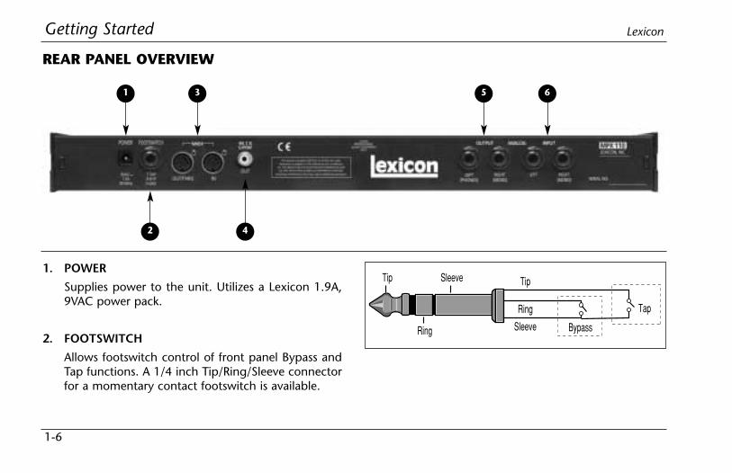
1. POWER
Supplies power to the unit. Utilizes a Lexicon 1.9A,9VAC power pack.
2. FOOTSWITCH
Allows footswitch control of front panel Bypass andTap functions. A 1/4 inch Tip/Ring/Sleeve connectorfor a momentary contact footswitch is available.
REAR PANEL OVERVIEW
1 3
2 4
5 6
Tip
Ring
Sleeve
Tip Sleeve
Ring
Tap
Bypass

Getting StartedMPX 110
1-7
3. MIDI IN, OUT/THRU
Provide MIDI operation capabilities. Two 5-pin DINMIDI connectors are available for MIDI IN andsoftware-selectable MIDI OUT/THRU.
4. S/PDIF OUT
Provides digital audio output. One RCA coaxialS/PDIF connector is available.
5. ANALOG OUTPUTs
Provide analog audio output. Two unbalanced,single-ended stereo output connectors are available.Both offer typical output levels of +8dBu. Use theRIGHT (MONO) OUTPUT for mono output. If noconnection is made to the RIGHT (MONO) OUTPUT,the LEFT (PHONES) OUTPUT can be used to driveheadphones at a modest volume.
6. ANALOG INPUTs
Provide analog audio input. Two unbalanced,single-ended stereo input connectors are available.Both accept levels as low as -30dBu. Inputimpedance is 500kΩ. These can be used as directinputs for guitars. Use the RIGHT (MONO) INPUT formono sources.
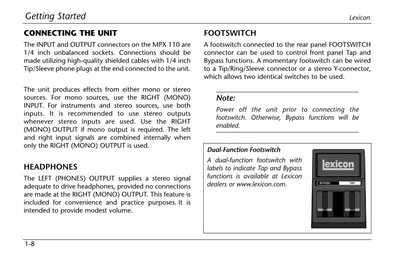
Dual-Function Footswitch
A dual-function footswitch withlabels to indicate Tap and Bypassfunctions is available at Lexicondealers or www.lexicon.com. BYPASS TAP
Getting Started Lexicon
1-8
CONNECTING THE UNITThe INPUT and OUTPUT connectors on the MPX 110 are1/4 inch unbalanced sockets. Connections should bemade utilizing high-quality shielded cables with 1/4 inchTip/Sleeve phone plugs at the end connected to the unit.
The unit produces effects from either mono or stereosources. For mono sources, use the RIGHT (MONO)INPUT. For instruments and stereo sources, use bothinputs. It is recommended to use stereo outputswhenever stereo inputs are used. Use the RIGHT(MONO) OUTPUT if mono output is required. The leftand right input signals are combined internally whenonly the RIGHT (MONO) OUTPUT is used.
HEADPHONESThe LEFT (PHONES) OUTPUT supplies a stereo signaladequate to drive headphones, provided no connectionsare made at the RIGHT (MONO) OUTPUT. This feature isincluded for convenience and practice purposes. It isintended to provide modest volume.
FOOTSWITCHA footswitch connected to the rear panel FOOTSWITCHconnector can be used to control front panel Tap andBypass functions. A momentary footswitch can be wiredto a Tip/Ring/Sleeve connector or a stereo Y-connector,which allows two identical switches to be used.
Note:Power off the unit prior to connecting thefootswitch. Otherwise, Bypass functions will beenabled.

Ch7 Ch8
AuxSend 1
AuxSend 2
RIGHT OutLEFT Out
RIGHT InLEFT In
Getting StartedMPX 110
1-9
The MPX 110 can be used as two independent effectsprocessors with DUAL program variations 11 to 16.Designate two auxiliary sends on the console. Connectthese to the unit - one to the LEFT INPUT and the otherto the RIGHT (MONO) INPUT. See Section 4 to takeadvantage of this configuration.
Right(Mono)Output
LeftOutput
Amplifier &Stereo Speaker
Cabinet
MPX 110
to MPX 110 RIGHT(MONO) INPUT
SB 210
0 10
56
7
8
91
3
2
4
0 10
56
7
8
91
3
2
4
0 10
56
7
8
91
3
2
4
0 10
56
7
8
91
3
2
4
0 10
56
7
8
91
3
2
4
0 10
56
7
8
91
3
2
4
0 10
56
7
8
91
3
2
4
Midrange TrebleRight
Volume
Left
VolumeBassGain
(Pull for Boost)Presence
Input
Standby
OnOn
Power
A l l T u b e C l a s s " A " S t e r e o R e c o r d i n g A m p l i f i e r a n d D i r e c t S o u r c e Designed by John McIntyre
Connecting to a Mono Guitar Input with Mono orStereo Amplifiers
Connecting to a Balanced Console
Connecting to a Dual Processor Setup with aConsole
Ring
MPX 110Output
Mixer InputTip Sleeve
MixerSend
MPX 110 Input
Tip 123
Sleeve
123
TipSleeve
Getting Started Lexicon
1-10
SETTING AUDIO LEVELS1. Begin with the Input knob set to the 9 o’clock
position.
2. Set the instrument or effects sends to a modestoutput level.
3. Begin playing or sending audio to the MPX 110. TheLevel LEDs should light green. If the Clip LEDs lightred, reduce the output level of the instrument oreffects sends until the Clip LEDs do not light duringthe loudest passages.
4. Continue to play or send audio to the MPX 110.Gradually increase the Input knob setting until theClip LEDs light red on the loudest passages.
5. Set the Mix knob to Dry.
6. Set the Output knob to the desired level.
7. If utilizing console sends and returns, set the Mixknob to Wet. If utilizing an instrument amplifier, setthe Mix knob to the 12 o’clock position.
The Level LEDs do not light when the incoming signal ismore than 30dB below overload. The Clip LEDs light redwhen the signal approaches overload (-2.5dB). When anacceptable signal is present, the Level LEDs light greenalmost continuously and the Clip LEDs flash red on theloudest passages.
Note:As with all audio products, it is good practice to firstpower on all outboard equipment, then the mixer,then the speakers.

Getting StartedMPX 110
1-11
REINITIALIZATIONThe procedure below outlines the process to reinitializethe unit. When reinitialized, the unit will restore allSystem Mode parameters to their factory-defaultsettings; replace all User programs with factory-defaultpresets; and clear all Learned Patches.
To reinitialize the unit:
1. While powering the unit on, press and hold the frontpanel Store button until the Store and Tap LEDs flashquickly.
2. To reinitialize the unit, press the Store button. Tocancel reinitialization without affecting the unit,press either the Tap or Bypass button.
3. After reinitialization, restart the unit - power it off,then on again.
Note:Reinitialization will cause the unit to:
• Restore all System Mode parameters to theirfactory-default settings.
• Replace all User programs with factory-defaultpresets. (See the table on page 4-38.)
• Clear all Learned Patches.
Basic Operation
2Adjust ..............................................................................................2-2
Selecting Programs..........................................................................2-2SINGLE Programs • DUAL Programs • User Programs
Editing Programs .............................................................................2-4
Storing Programs.............................................................................2-4
Tap Tempo ......................................................................................2-5Varying Rhythm • Audio Tap • Global Tempo
Bypass .............................................................................................2-6
Basic Operation Lexicon
2-2
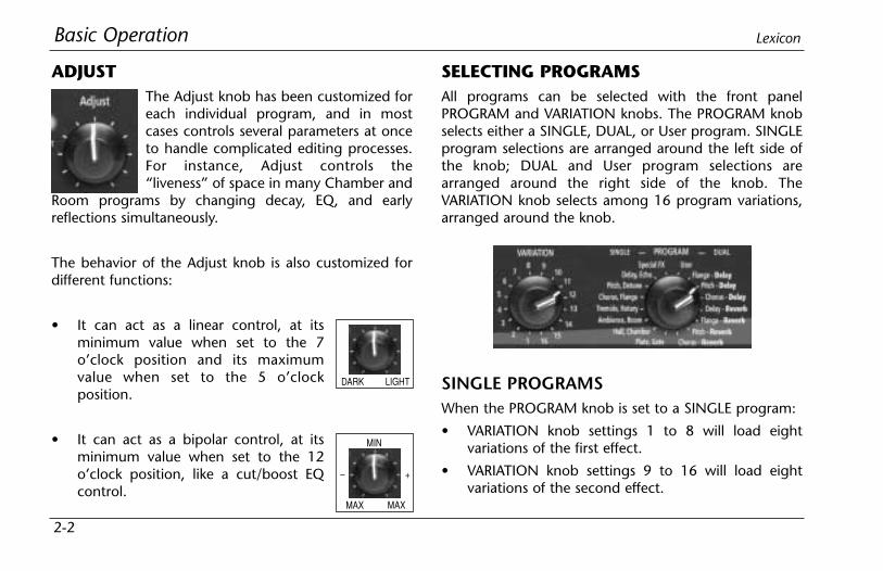
ADJUSTThe Adjust knob has been customized foreach individual program, and in mostcases controls several parameters at onceto handle complicated editing processes.For instance, Adjust controls the“liveness” of space in many Chamber and
Room programs by changing decay, EQ, and earlyreflections simultaneously.
The behavior of the Adjust knob is also customized fordifferent functions:
• It can act as a linear control, at itsminimum value when set to the 7o’clock position and its maximumvalue when set to the 5 o’clockposition.
• It can act as a bipolar control, at itsminimum value when set to the 12o’clock position, like a cut/boost EQcontrol.
SELECTING PROGRAMSAll programs can be selected with the front panelPROGRAM and VARIATION knobs. The PROGRAM knobselects either a SINGLE, DUAL, or User program. SINGLEprogram selections are arranged around the left side ofthe knob; DUAL and User program selections arearranged around the right side of the knob. TheVARIATION knob selects among 16 program variations,arranged around the knob.
DARK LIGHT
MAX
MIN
MAX
+–
SINGLE PROGRAMSWhen the PROGRAM knob is set to a SINGLE program:
• VARIATION knob settings 1 to 8 will load eightvariations of the first effect.
• VARIATION knob settings 9 to 16 will load eightvariations of the second effect.
Basic OperationMPX 110
2-3
• See pages 4-2 to 4-17 for more information aboutSINGLE programs.
For example, when Plate, Gate is selected:
• VARIATION knob settings 1 to 8 will load eightdifferent Plate program variations.
• VARIATION knob settings 9 to 16 will load eightdifferent Gate program variations.
When Special FX is selected:
• VARIATION knob settings 1 to 16 will each load oneprogram.
• See page 4-18 for more information.
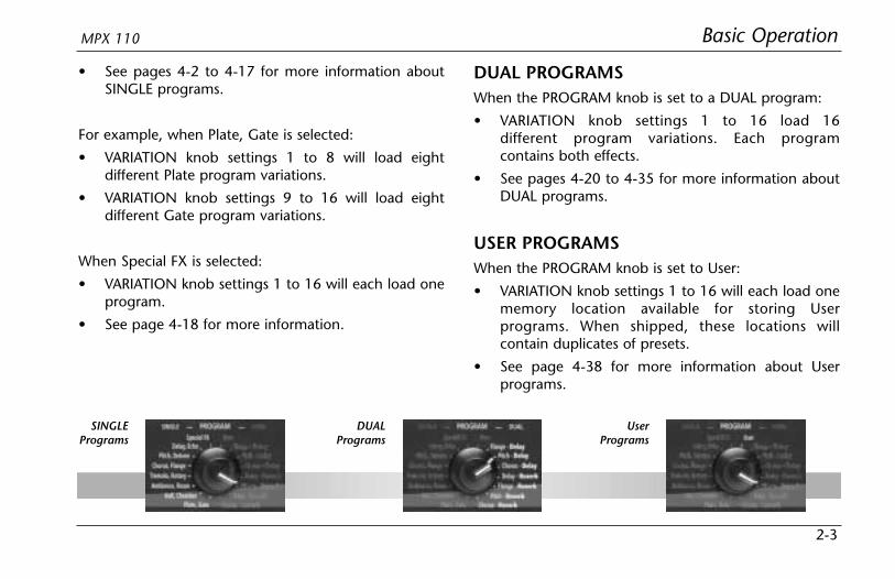
DUAL PROGRAMSWhen the PROGRAM knob is set to a DUAL program:
• VARIATION knob settings 1 to 16 load 16different program variations. Each programcontains both effects.
• See pages 4-20 to 4-35 for more information aboutDUAL programs.
USER PROGRAMSWhen the PROGRAM knob is set to User:
• VARIATION knob settings 1 to 16 will each load onememory location available for storing Userprograms. When shipped, these locations willcontain duplicates of presets.
• See page 4-38 for more information about Userprograms.
SINGLEPrograms
DUALPrograms
UserPrograms

Basic Operation Lexicon
2-4
EDITING PROGRAMSThe front panel Adjust and Effects Lvl/Bal knobs can bothbe used to edit programs. The Adjust knob providesinstant manipulation of critical program parameters.These parameters are arranged under the knob, meaningthat just one turn is all that is required to customize aprogram to personal taste. The Effects Lvl/Bal knob canbe used to control effect level in SINGLE programs, oreffect balance in DUAL programs.
The unit recognizes changes made with either knob asedits. When edits are made, the front panel Edit LED willlight to indicate that the selected program has beenmodified but not stored.
STORING PROGRAMSTo store a program in a User memory location:
1. Press the Store button. The Store LED willflash slowly to indicate that the storefunction is activated.
2. To continue saving the program, set the PROGRAMknob to User. To cancel the store function withoutsaving the program, make sure the PROGRAM knobis not set to User, then press the Store button again.
3. Set the VARIATION knob to select one of the 16 Usermemory locations.
4. Press the Store button to save the program to theselected location. The Store LED will flash quicklyuntil the store process is complete. The Edit LED willno longer be lit when the saved version becomes theselected program.
Use the Adjust knob to edit theselected program, and the EffectsLvl/Bal knob to control effect level inSINGLE programs or effect balancein DUAL Programs. The Edit LED willlight to indicate that the selectedprogram has been modified from itsstored condition.

Basic OperationMPX 110
2-5
TAP TEMPO
VARYING RHYTHMTap Tempo can be used to match the delaytimes and modulation rates of tempo-basedprograms with those of the music. The Tap LEDwill flash whenever a tempo-based preset is loaded. Toset tempo from the front panel, press the Tap buttontwice in time with the music. It is not required to enterwhat could be the delay time in milliseconds. Just pressthe Tap button twice, and the unit will calculate theappropriate delay time. To change tempo, press the Tapbutton twice again in the new rhythm. Changes made totempo with the Tap button are not considered programedits, and will not cause the Edit LED to light.
AUDIO TAPTo use audio input to set tempo:
1. Press and hold the Tap button for 2seconds. (The optional dual footswitchallows the musician to remain in contactwith the instrument while pressing and holding theTap button.)
2. While holding the Tap button, play two short notesin rhythm, then release the Tap button. The unit willautomatically calculate tempo based on the timelapse between the two notes.
Audio tap is a must for live performances. It offers asimple method of setting delay times and modulationrates to match the music.
. . . continued on page 2-6
When new programs are stored in a User memorylocation, programs that were previously stored at thatlocation will be automatically replaced.
CAUTION
Basic Operation Lexicon
2-6
Tap Tempo (continued from page 2-5)
GLOBAL TEMPOMost factory presets are stored with individual temporates, which can be customized to suit personal taste.Tap in the new tempo, then store the modified version ofthe preset in a User memory location (see page 2-4).
To recall the tempo rate stored with each program, setthe System Mode parameter Tempo to Program. Theunit will apply the individual tempo setting of eachprogram as it is loaded. To apply the current tempo rateto all programs, set the System Mode parameter Tempoto Global. The unit will ignore individual tempo settingsand apply the current tempo setting to each program asit is loaded. (The Tap LED will flash when a tempo-controlled program is loaded.)
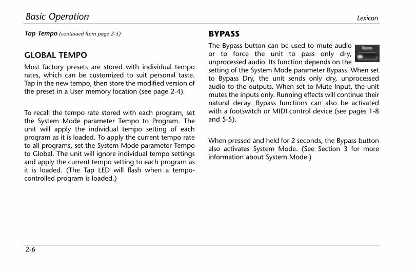
BYPASSThe Bypass button can be used to mute audioor to force the unit to pass only dry,unprocessed audio. Its function depends on thesetting of the System Mode parameter Bypass. When setto Bypass Dry, the unit sends only dry, unprocessedaudio to the outputs. When set to Mute Input, the unitmutes the inputs only. Running effects will continue theirnatural decay. Bypass functions can also be activatedwith a footswitch or MIDI control device (see pages 1-8and 5-5).
When pressed and held for 2 seconds, the Bypass buttonalso activates System Mode. (See Section 3 for moreinformation about System Mode.)

System Mode
3Overview .........................................................................................3-2
System Mode Parameters & Functions.............................................3-3

Use the Edit LED to determine thecurrent setting of the selectedparameter. See the next page formore information.
System Mode Lexicon
3-2
System Mode can be used to configure System Modeparameters and execute MIDI Dumps. To enter SystemMode, press and hold the front panel Bypass button forapproximately 2 seconds. The Bypass and Store LEDs willflash slowly to indicate that System Mode is active.
The table on the next page shows System Modeparameters and functions. The VARIATION knob selectsthe desired parameter or function. Settings 1 to 8 selectSystem Mode parameters. Settings 14 to 16 select MIDIDumps.
The Edit LED shows the current setting of the selectedparameter (see the table on the next page). Press theStore button to toggle the parameter setting. WhenVARIATION knob settings 14, 15, or 16 are selected,press the Store button to execute the selected MIDIDump.
When finished, reset the VARIATION knob to its originalsetting before System Mode was activated. Otherwise, anew program will load based on this setting whenSystem Mode is deactivated. Use the Tap LED todetermine if the VARIATION knob has beenreset; it will light when the knob is set to the lastloaded program.
To exit System Mode, press the Bypass button. The StoreLED will flash quickly to indicate that parameter settingshave changed. (The Store LED will not flash if no changeswere made.)
Descriptions of all System Mode parameters andfunctions are available on pages 3-3 to 3-5.
Press the Bypassbutton to enter andexit System Mode. Use the VARIATION
knob to select thedesired parameteror function.
Press the Store button to toggle thesetting of the selected parameter orto execute the selected MIDI Dump.
System ModeMPX 110
3-3
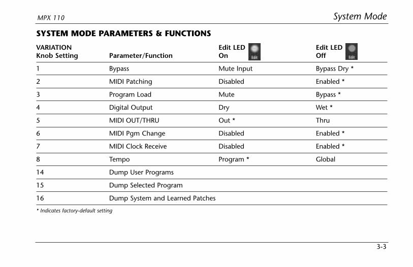
SYSTEM MODE PARAMETERS & FUNCTIONS
VARIATION Edit LED Edit LEDKnob Setting Parameter/Function On Off
1 Bypass Mute Input Bypass Dry *
2 MIDI Patching Disabled Enabled *
3 Program Load Mute Bypass *
4 Digital Output Dry Wet *
5 MIDI OUT/THRU Out * Thru
6 MIDI Pgm Change Disabled Enabled *
7 MIDI Clock Receive Disabled Enabled *
8 Tempo Program * Global
14 Dump User Programs
15 Dump Selected Program
16 Dump System and Learned Patches
* Indicates factory-default setting
System Mode Lexicon
3-4
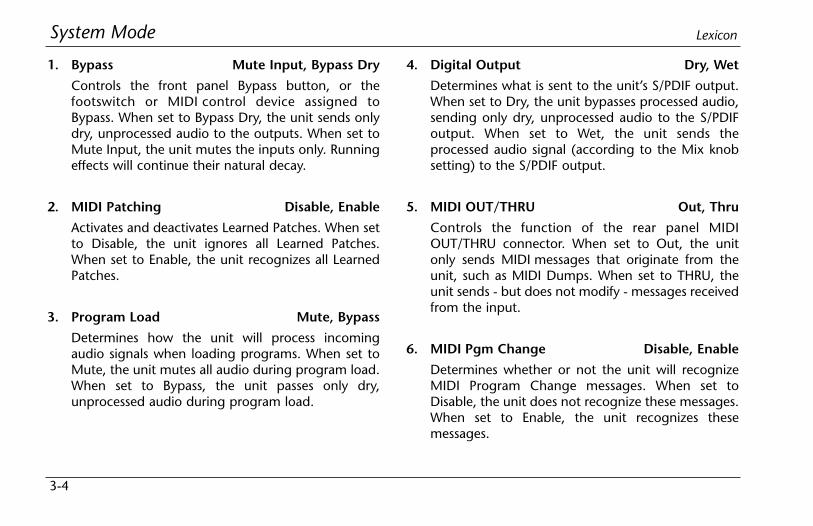
1. Bypass Mute Input, Bypass Dry
Controls the front panel Bypass button, or thefootswitch or MIDI control device assigned toBypass. When set to Bypass Dry, the unit sends onlydry, unprocessed audio to the outputs. When set toMute Input, the unit mutes the inputs only. Runningeffects will continue their natural decay.
2. MIDI Patching Disable, Enable
Activates and deactivates Learned Patches. When setto Disable, the unit ignores all Learned Patches.When set to Enable, the unit recognizes all LearnedPatches.
3. Program Load Mute, Bypass
Determines how the unit will process incomingaudio signals when loading programs. When set toMute, the unit mutes all audio during program load.When set to Bypass, the unit passes only dry,unprocessed audio during program load.
4. Digital Output Dry, Wet
Determines what is sent to the unit’s S/PDIF output.When set to Dry, the unit bypasses processed audio,sending only dry, unprocessed audio to the S/PDIFoutput. When set to Wet, the unit sends theprocessed audio signal (according to the Mix knobsetting) to the S/PDIF output.
5. MIDI OUT/THRU Out, Thru
Controls the function of the rear panel MIDIOUT/THRU connector. When set to Out, the unitonly sends MIDI messages that originate from theunit, such as MIDI Dumps. When set to THRU, theunit sends - but does not modify - messages receivedfrom the input.
6. MIDI Pgm Change Disable, Enable
Determines whether or not the unit will recognizeMIDI Program Change messages. When set toDisable, the unit does not recognize these messages.When set to Enable, the unit recognizes thesemessages.

System ModeMPX 110
3-5
7. MIDI Clock Receive Disable, Enable
Determines whether or not the unit will use MIDIClock messages to set tempo. When set to Disable,the unit ignores these messages. When set to Enable,the unit recognizes these messages. (This parameterhas no effect on programs that are not tempo-based.)
8. Tempo Program, Global
Controls the application of tempo to tempo-basedprograms. When set to Program, the unit applies theprogram-specific tempo of each program as it isloaded. When set to Global, the unit maintains thecurrent tempo that was entered by any means asprograms are loaded. (This parameter has no effecton programs that are not tempo-based).
14. Dump User Programs
Executes a MIDI Dump of User programs to anexternal MIDI device, such as a sequencer. Theseprograms can be dumped back to the unit, which isuseful for preserving User programs when defaultsettings are restored. When VARIATION knob setting
14 is selected, press the front panel Store button toexecute the dump. When dumped back, Userprograms will be returned to their original locations.
15. Dump Selected Program
Executes a MIDI Dump of the currently activeprogram, allowing programs to be saved to anexternal MIDI device. When VARIATION knob setting15 is selected, press the front panel Store button toexecute this dump. When dumped back, theprogram will automatically become the currentlyactive program.
16. Dump System and Learned Patches
Executes a MIDI Dump of all System Modeparameter settings and Learned Patches. WhenVARIATION knob setting 16 is selected, press thefront panel Store button to execute the dump. Whendumped back, the System Mode settings andLearned patches will take effect immediately.

Program Descriptions
4SINGLE Programs ............................................................................4-2
Plate • Gate • Hall • Chamber • Ambience • Room • Tremolo • Rotary • Chorus •Flange • Pitch • Detune • Delay, Echo
Special FX......................................................................................4-18
DUAL Programs .............................................................................4-20Effects Lvl/Bal • Flange-Delay • Pitch-Delay • Chorus-Delay • Delay-Reverb •Flange-Reverb • Pitch-Reverb • Chorus-Reverb
The Pitch Programs .......................................................................4-36
User Programs ...............................................................................4-38

Program Descriptions Lexicon
4-2
SINGLE PROGRAMS
PLATEPlate reverb began with a large, thin sheet of metalsuspended upright under tension on springs.Transducers attached to the plate transmitted a signalthat made the plate vibrate, causing sounds broadcastthrough it to appear to be occurring in a large, openspace.
The Plate programs synthesize the sound of metal plateswith high initial diffusion and a relatively bright-coloredsound. These programs are designed to be heard as partof the music, mellowing and thickening the sound. Plateprograms are a popular choice for enhancing pop music,particularly percussion.
VARIATIONs Adjust Tap
1 Small Plate Liveness* –
2 Medium Plate Liveness* –
3 Large Plate Liveness* PreDelay(1/32 Note)
4 Larger Plate Decay Time* PreDelay(1/32 Note)
5 Tape Slap ±Decay/ –Plate 15 or 7.5ips**
6 Rich Plate Decay Time* PreDelay(1/32 Note)
7 Large Bright Decay Time* PreDelayPlate (1/32 Note)
8 Vocal Plate Low Cut, EchoDecay Time*
* The Adjust knob functions as a linear control in these variations. Seepage 2-2 for more information.
** When the Adjust knob is set to the left of the 12 o’clock position, decayis 15ips. When the Adjust knob is set to the right of the 12 o’clockposition, decay is 7.5ips.
Program DescriptionsMPX 110
4-3
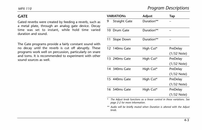
GATEGated reverbs were created by feeding a reverb, such asa metal plate, through an analog gate device. Decaytime was set to instant, while hold time variedduration and sound.
The Gate programs provide a fairly constant sound withno decay until the reverb is cut off abruptly. Theseprograms work well on percussion, particularly on snareand toms. It is recommended to experiment with othersound sources as well.
VARIATIONs Adjust Tap
9 Straight Gate Duration** –
10 Drum Gate Duration** –
11 Slope Down Duration** –
12 140ms Gate High Cut* PreDelay
(1/32 Note)
13 240ms Gate High Cut* PreDelay
(1/32 Note)
14 340ms Gate High Cut* PreDelay
(1/32 Note)
15 440ms Gate High Cut* PreDelay
(1/32 Note)
16 540ms Gate High Cut* PreDelay
(1/32 Note)* The Adjust knob functions as a linear control in these variations. See
page 2-2 for more information.
** Audio will be briefly muted when Duration is altered with the Adjustknob.
Program Descriptions Lexicon
4-4
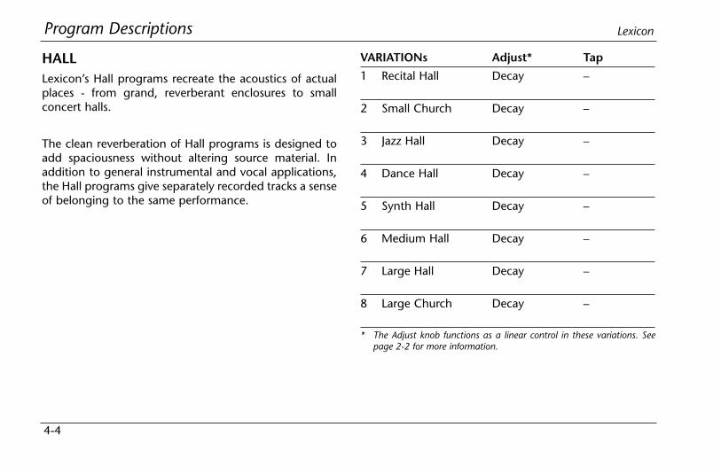
HALLLexicon’s Hall programs recreate the acoustics of actualplaces - from grand, reverberant enclosures to smallconcert halls.
The clean reverberation of Hall programs is designed toadd spaciousness without altering source material. Inaddition to general instrumental and vocal applications,the Hall programs give separately recorded tracks a senseof belonging to the same performance.
VARIATIONs Adjust* Tap
1 Recital Hall Decay –
2 Small Church Decay –
3 Jazz Hall Decay –
4 Dance Hall Decay –
5 Synth Hall Decay –
6 Medium Hall Decay –
7 Large Hall Decay –
8 Large Church Decay –
* The Adjust knob functions as a linear control in these variations. Seepage 2-2 for more information.
Program DescriptionsMPX 110
4-5
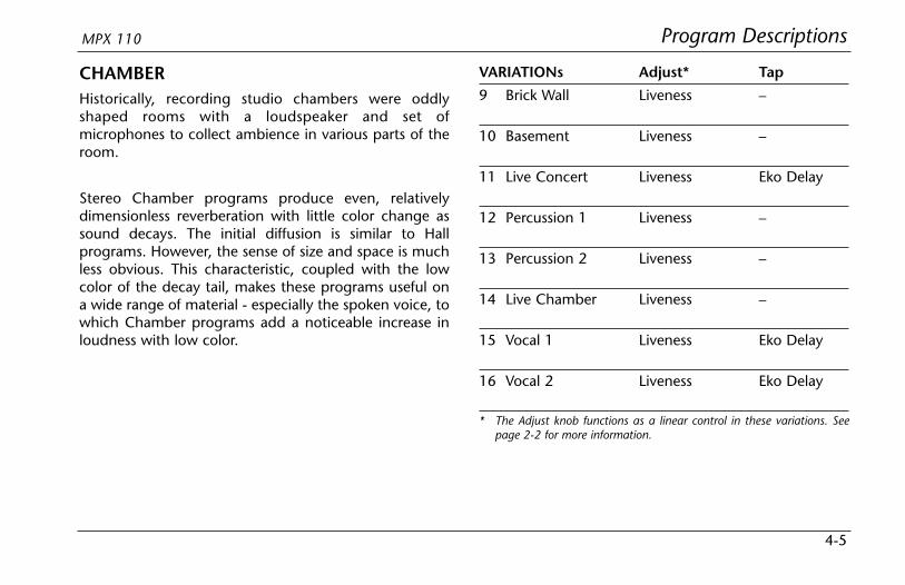
CHAMBERHistorically, recording studio chambers were oddlyshaped rooms with a loudspeaker and set ofmicrophones to collect ambience in various parts of theroom.
Stereo Chamber programs produce even, relativelydimensionless reverberation with little color change assound decays. The initial diffusion is similar to Hallprograms. However, the sense of size and space is muchless obvious. This characteristic, coupled with the lowcolor of the decay tail, makes these programs useful ona wide range of material - especially the spoken voice, towhich Chamber programs add a noticeable increase inloudness with low color.
VARIATIONs Adjust* Tap
9 Brick Wall Liveness –
10 Basement Liveness –
11 Live Concert Liveness Eko Delay
12 Percussion 1 Liveness –
13 Percussion 2 Liveness –
14 Live Chamber Liveness –
15 Vocal 1 Liveness Eko Delay
16 Vocal 2 Liveness Eko Delay
* The Adjust knob functions as a linear control in these variations. Seepage 2-2 for more information.

Program Descriptions Lexicon
4-6
AMBIENCEAmbience adds warmth, spaciousness, and depth to aperformance without coloring its direct sound. It iscommonly used to add a room sound to recorded musicand speech. In music recording, Ambience canrealistically add distance to close-mic’ed signals.
Ambience programs simulate reflections from roomsurfaces with random reflections, a gradual decay ofoverall level, and a gradual narrowing of bandwidth. Inthese programs, the Mix control adds depth - emulatingthe movement of a coincident pair of microphones awayfrom the sound source into the room.
Variations 1 to 8 provide a series of rooms, increasing insize.
VARIATIONs Adjust* Tap
1 Voice Over High Cut –
2 Very Small High Cut –
Ambience
3 Small High Cut –
Ambience
4 Medium High Cut –
Ambience
5 Studio D High Cut –
6 Bright Decay Level –
Ambience
7 Dark Decay Level –
Ambience
8 Marble Foyer Liveness –
* The Adjust knob functions as a linear control in these variations. Seepage 2-2 for more information.
Program DescriptionsMPX 110
4-7
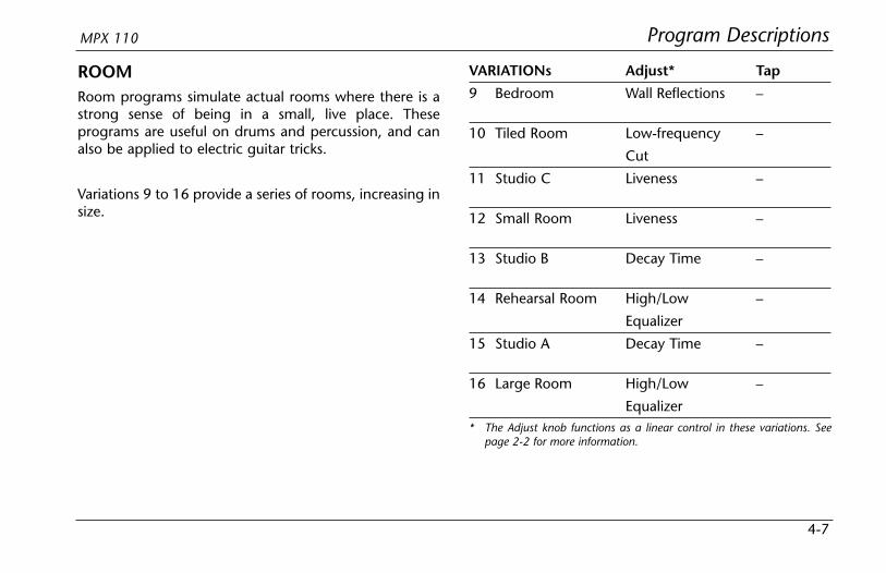
ROOMRoom programs simulate actual rooms where there is astrong sense of being in a small, live place. Theseprograms are useful on drums and percussion, and canalso be applied to electric guitar tricks.
Variations 9 to 16 provide a series of rooms, increasing insize.
VARIATIONs Adjust* Tap
9 Bedroom Wall Reflections –
10 Tiled Room Low-frequency –
Cut
11 Studio C Liveness –
12 Small Room Liveness –
13 Studio B Decay Time –
14 Rehearsal Room High/Low –
Equalizer
15 Studio A Decay Time –
16 Large Room High/Low –
Equalizer* The Adjust knob functions as a linear control in these variations. See
page 2-2 for more information.
Program Descriptions Lexicon
4-8
TREMOLOTremolo is a rhythmic change in loudness, commonlyemployed as an expressive technique by vocalists andwind instrument players. It is also one of the oldestelectronic effects, frequently used with electric guitar,electric piano, and occasionally vocals. Different tremoloeffects are largely determined by the rate (fast or slow)and waveform shape (smooth or sharp) of the change inloudness. If the effect is used in a stereo mix, the left andright can be synchronized to produce dramatic side-to-side motion.
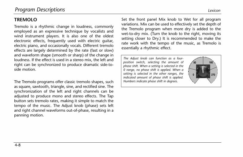
The Tremolo programs offer classic tremolo shapes, suchas square, sawtooth, triangle, sine, and rectified sine. Thesynchronization of the left and right channels can beadjusted to produce mono and stereo effects. The Tapbutton sets tremolo rates, making it simple to match thetempo of the music. The Adjust knob (phase) sets leftand right channel waveforms out-of-phase, resulting in apanning motion.
Set the front panel Mix knob to Wet for all programvariations. Mix can be used to effectively set the depth ofthe Tremolo program when more dry is added to thewet-to-dry mix. (Turn the knob to the right, moving itssetting closer to Dry.) It is recommended to make therate work with the tempo of the music, as Tremolo isessentially a rhythmic effect.
The Adjust knob can function as a four-position switch, selecting the amount ofphase shift. When a setting is selected in the0 range, no phase shift is applied. When asetting is selected in the other ranges, theindicated amount of phase shift is applied.Numbers indicate phase shift in degrees.
90 180
2700

Program DescriptionsMPX 110
4-9
VARIATIONs Adjust Tap
1 Rectified Sine Wave Rate: –0.4 to 15Hz*
2 Square Wave Rate: –0.4 to 15Hz*
3 Sawtooth Wave Rate: –0.4 to 15Hz*
4 Rectified Sine Wave Sweep: Rate0, 90, 180, 270** (1/4 Note)
5 Square Wave Sweep: Rate0, 90, 180, 270** (1/4 Note)
6 Sawtooth Wave Sweep: Rate0, 90, 180, 270** (1/4 Note)
7 Triangle Wave Sweep: Rate0, 90, 180, 270** (1/4 Note)
8 Sine Wave Sweep: Rate0, 90, 180, 270** (1/4 Note)
* The Adjust knob functions as a linear control in these variations. Seepage 2-2 for more information.
** The Adjust knob functions as a four-position switch in thesevariations. See page 4-8 for more information.

Program Descriptions Lexicon
4-10
ROTARYRotary speaker cabinets were designed to provide amajestic vibrato/choir effect for electronic theater andchurch organs. The most well known rotary speaker isthe Leslie™ Model 122, which has two counter-rotatingelements: a high-frequency horn and a low-frequencyrotor with slow and fast speeds. The sound generated asthe spinning elements change speed is truly magical.The swirling, spacious effect is difficult to describe - butclearly recognizable.
The Rotary programs are a detailed simulation of aLeslie-style cabinet. The input signal is split into high andlow-frequency bands. The rotation effect is created by asynchronized combination of pitch shifting, tremolo,and panning. Like the physical cabinet, the high (horn)and low (rotor) frequencies are “spun” in oppositedirections. Horn and rotor speeds are independent, anddesigned with acceleration and decelerationcharacteristics to simulate the inertia of the originalmechanical elements.
A virtual requirement for organ music, Rotary programsalso sound remarkable with guitar and electric pianorhythm parts. In fact, these programs are greatalternatives to chorus and tremolo effects for any soundsource.
To achieve the full effect, set the front panel Mix knob toWet for all variations of this program (9 to 16).

Program DescriptionsMPX 110
4-11
VARIATIONs Adjust Tap
9 Rotary Slow/Fast –
10 Rotary Slow/Fast, –Width
11 Rotary Slow/Fast, –Balance
12 Slow Rotary ±Resonance* –
13 Varispeed Speed –Rotary
14 Tap Rotary Balance Rate
(1/4 Note)
15 Tap Rotary Width Rate(1/4 Note)
16 Tap Rotary ±Resonance* Rate(1/4 Note)
* The Adjust knob functions as a bipolar control in these variations. Seepage 2-2 for more information.

Program Descriptions Lexicon
4-12
CHORUSChorus effects create lush, full sounds by multiplying theoriginal audio source. Traditionally, these effects wereused to fatten up tracks and to add body to guitarwithout coloring the original tone. Chorus effects arealso often combined with plates, echoes, and otherreverb effects.
The stereo Chorus programs, inherited from Lexicon’sPCM 80, create a rich, airy effect that simulates thesound of multiple sources from a single source. Theseprograms are stunning on acoustic or clean-electricguitar.
These programs utilize six independently-randomizeddelay voices panned across the stereo field. Set the frontpanel Mix knob to Wet to achieve the full richness of the6-voice chorus.
VARIATIONs Adjust Tap
1 Rich Chorus ± Resonance* –
2 Rich Chorus ± Depth* –
3 Rich Chorus Rate –
4 Rich Chorus High Cut –
5 Diffuse Chorus Diffusion –
6 Slap Chorus Diffusion –
7 Slap Chorus ± Resonance* –
8 Slap Chorus ± Depth* –
* The Adjust knob functions as a bipolar control in these variations. Seepage 2-2 for more information.
Program DescriptionsMPX 110
4-13
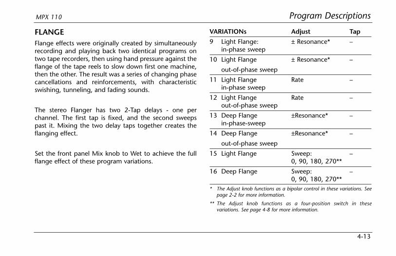
FLANGEFlange effects were originally created by simultaneouslyrecording and playing back two identical programs ontwo tape recorders, then using hand pressure against theflange of the tape reels to slow down first one machine,then the other. The result was a series of changing phasecancellations and reinforcements, with characteristicswishing, tunneling, and fading sounds.
The stereo Flanger has two 2-Tap delays - one perchannel. The first tap is fixed, and the second sweepspast it. Mixing the two delay taps together creates theflanging effect.
Set the front panel Mix knob to Wet to achieve the fullflange effect of these program variations.
VARIATIONs Adjust Tap
9 Light Flange: ± Resonance* –in-phase sweep
10 Light Flange ± Resonance* –
out-of-phase sweep
11 Light Flange Rate –in-phase sweep
12 Light Flange Rate –out-of-phase sweep
13 Deep Flange ±Resonance* –in-phase-sweep
14 Deep Flange ±Resonance* –
out-of-phase sweep
15 Light Flange Sweep: –0, 90, 180, 270**
16 Deep Flange Sweep: –0, 90, 180, 270**
* The Adjust knob functions as a bipolar control in these variations. Seepage 2-2 for more information.
** The Adjust knob functions as a four-position switch in thesevariations. See page 4-8 for more information.
Program Descriptions Lexicon
4-14
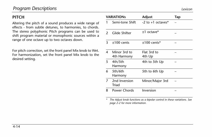
PITCHAltering the pitch of a sound produces a wide range ofeffects - from subtle detunes, to harmonies, to chords.The stereo polyphonic Pitch programs can be used toshift program material or monophonic sources within arange of one octave up to two octaves down.
For pitch correction, set the front panel Mix knob to Wet.For harmonization, set the front panel Mix knob to thedesired setting.
VARIATIONs Adjust Tap
1 Semi-tone Shift -2 to +1 octaves* –
2 Glide Shifter ±1 octave* –
3 ±100 cents ±100 cents* –
4 Minor 3rd to Flat 3rd to –4th Harmony 4th Up
5 4th/5th 4th to 5th Up –Harmony
6 5th/6th 5th to 6th Up –Harmony
7 2nd Inversion Minor/Major 3rd –Triad
8 Power Chords Inversion –
* The Adjust knob functions as a bipolar control in these variations. Seepage 2-2 for more information.
Program DescriptionsMPX 110
4-15
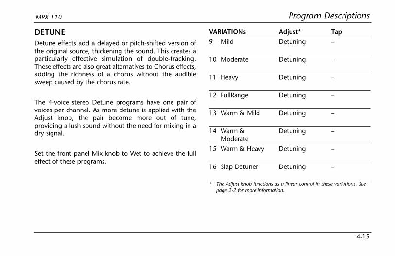
DETUNEDetune effects add a delayed or pitch-shifted version ofthe original source, thickening the sound. This creates aparticularly effective simulation of double-tracking.These effects are also great alternatives to Chorus effects,adding the richness of a chorus without the audiblesweep caused by the chorus rate.
The 4-voice stereo Detune programs have one pair ofvoices per channel. As more detune is applied with theAdjust knob, the pair become more out of tune,providing a lush sound without the need for mixing in adry signal.
Set the front panel Mix knob to Wet to achieve the fulleffect of these programs.
VARIATIONs Adjust* Tap
9 Mild Detuning –
10 Moderate Detuning –
11 Heavy Detuning –
12 FullRange Detuning –
13 Warm & Mild Detuning –
14 Warm & Detuning –Moderate
15 Warm & Heavy Detuning –
16 Slap Detuner Detuning –
* The Adjust knob functions as a linear control in these variations. Seepage 2-2 for more information.

Program Descriptions Lexicon
4-16
DELAY, ECHODelays and echoes repeat a sound a short time after itfirst occurs. The simplest (and oldest) delay effect is tapeslap - a single repeat about 100ms after the originalsound. Tape slap was often used on Elvis Presley’s voiceand rockabilly guitar tracks.
Tape slap becomes tape echo when the output of thetape is fed back into the input (feedback). This turns asingle repeat into a series of repeats, each a little softerand a little darker than the last. This darkening ischaracteristic of the analog tape recording process.Digital delays do not have this characteristic; each repeathas the same exact timbre. For digital delays, loudness isthe only difference from repeat to repeat.
Tape echo and digital delay are both useful, butdifferent. Tape echo is warmer, allowing the originalsound to distinguish itself. Digital delay presents a“perfect” copy of the original sound.
The Delay and Echo variations include mono (5.5seconds), stereo (2.7 seconds), and 6-voice multi-tap
effects. Each program can be used for tape echo ordigital delay effects.
When the Adjust knob is set to avalue between 12 and 5 o’clock,tape echo effects are produced. Eachrepeat is darker and softer. When theAdjust knob is set to a value between7 and 12 o’clock, digital delay effects are produced. Eachrepeat is the same timbre, but softer.
In variations 1 to 8, the Adjust knob sets the amount offeedback with an increasing number of repeats as thesetting is increased. Delay time is set with Tap. Eachprogram is preset with a different rhythm. Invariations 9 to 16, the amount of feedback is preset andthe Adjust knob determines the delay time.
With all Delay and Echo effects, note the way the repeatsfall rhythmically to the beat. The most effective Delayand Echo patterns are those that lock with the tempo ofthe music.
MAX
MIN
MAX
EchoesDelays
Program DescriptionsMPX 110
4-17
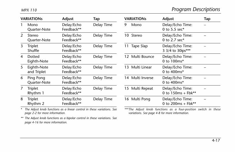
VARIATIONs Adjust Tap
1 Mono Delay/Echo Delay TimeQuarter-Note Feedback**
2 Stereo Delay/Echo Delay TimeQuarter-Note Feedback**
3 Triplet Delay/Echo Delay TimeShuffle Feedback**
4 Dotted Delay/Echo Delay TimeEighth-Note Feedback**
5 Eighth-Note Delay/Echo Delay Timeand Triplet Feedback**
6 Ping Pong Delay/Echo Delay TimeQuarter-Note Feedback**
7 Triplet Delay/Echo Delay TimeRhythm 1 Feedback**
8 Triplet Delay/Echo Delay TimeRhythm 2 Feedback**
* The Adjust knob functions as a linear control in these variations. Seepage 2-2 for more information.
** The Adjust knob functions as a bipolar control in these variations. Seepage 4-16 for more information.
VARIATIONs Adjust Tap
9 Mono Delay/Echo Time: –0 to 5.5 sec*
10 Stereo Delay/Echo Time: –0 to 2.7 sec*
11 Tape Slap Delay/Echo Time: –3 3/4 to 30ips***
12 Multi Bounce Delay/Echo Time: –0 to 100ms*
13 Multi Linear Delay/Echo Time: –0 to 400ms*
14 Multi Inverse Delay/Echo Time: –0 to 400ms*
15 Multi Repeat Delay/Echo Time: –0 to 150ms + Fbk**
16 Multi Pong Delay/Echo Time: –0 to 200ms + Fbk**
***The Adjust knob functions as a four-position switch in thesevariations. See page 4-8 for more information.
Program Descriptions Lexicon
4-18
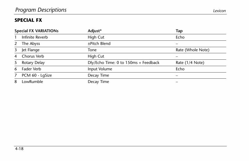
Special FX VARIATIONs Adjust* Tap
1 Infinite Reverb High Cut Echo
2 The Abyss ±Pitch Blend –
3 Jet Flange Tone Rate (Whole Note)
4 Chorus Verb High Cut –
5 Rotary Delay Dly/Echo Time: 0 to 150ms + Feedback Rate (1/4 Note)
6 Fader Verb Input Volume Echo
7 PCM 60 - LgSize Decay Time –
8 LowRumble Decay Time –
SPECIAL FX
Program DescriptionsMPX 110
4-19
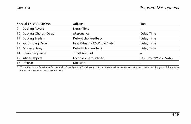
Special FX VARIATIONs Adjust* Tap
9 Ducking Reverb Decay Time –
10 Ducking Chorus>Delay ±Resonance Delay Time
11 Ducking Triplets Delay/Echo Feedback Delay Time
12 Subdividing Delay Beat Value: 1/32-Whole Note Delay Time
13 Panning Delays Delay/Echo Feedback Delay Time
14 Dream Sequence ±Shift Amount –
15 Infinite Repeat Feedback: 0 to Infinite Dly Time (Whole Note)
16 Diffusor Diffusion –* The Adjust knob function differs in each of the Special FX variations. It is recommended to experiment with each program. See page 2-2 for more
information about Adjust knob functions.

Program Descriptions Lexicon
4-20
DUAL PROGRAMSThe DUAL Programs combine Delay with Reverb, oreither Delay or Reverb with Chorus, Flange, or Pitch.Four routing configurations are used in the variations ofeach DUAL program: Dual Stereo (Parallel), Cascade,Mono Split, and Dual Mono.
Variation knob settings are configured as follows:
• Variations 1 to 6 are arranged in the Dual Stereo(Parallel) configuration - two stereo effects placednext to one another to receive and output stereoaudio from both the left and right channels.
• Variations 7 to 10 are arranged in the Cascadeconfiguration - two stereo effects, one placed afterthe other. For example, in Flange-Delay, Flangepasses its stereo signal to Delay.
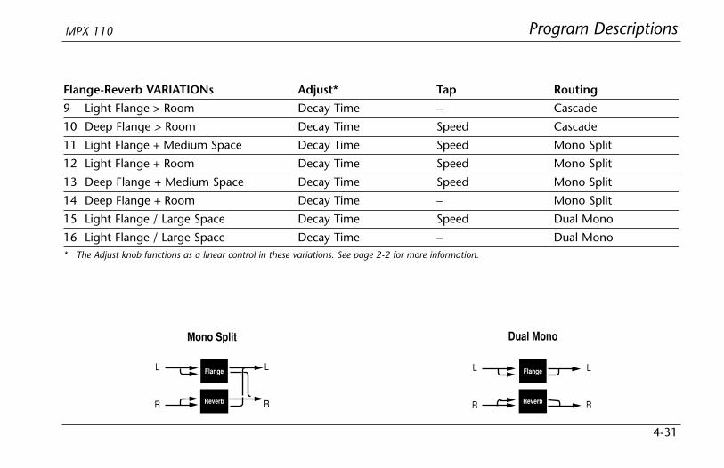
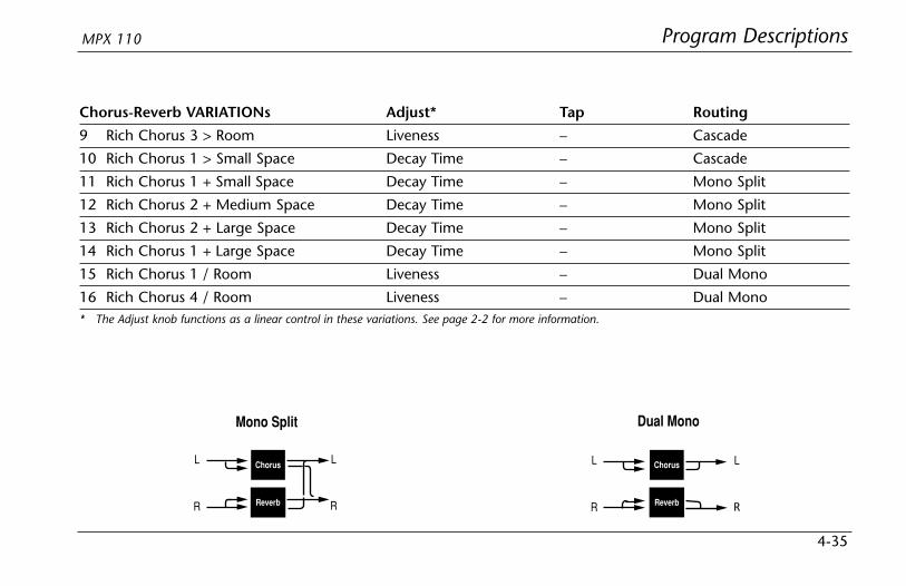
• Variations 11 to 14 are arranged in the Mono Splitconfiguration, which is similar to the Dual Stereo(Parallel) configuration. One effect (Flange) receivesaudio from the left input and the other effect (Delay)receives audio from the right input. Both effectsoutput stereo audio.
• Variations 15 and 16 are arranged in the Dual Monoconfiguration where one effect (Flange) appears onthe left channel only, while the other effect (Delay)appears on the right channel only.
Dual Stereo (Parallel)
Flange
Delay
L
R
L
R
Cascade
Flange DelayLR
LR
Mono Split
Flange
Delay
L
R
L
R
Dual Mono
Flange
Delay
L
R
L
R

Program DescriptionsMPX 110
4-21
EFFECTS LVL/BALThe front panel Effects Lvl/Bal knob controls the relativebalance of each effect in the DUAL program. In Cascadevariations, the knob also varies the amount of the firsteffect or dry signal fed into the second effect.
The illustration below uses the Pitch-Delay program toshow the behavior of the Effects Lvl/Bal knob at certainsettings when a Cascade variation is selected.
Pitch Delay
Pitch Delay Pitch Delay
Pitch DelayDelayPitch
12 o’clock: Provides delayed pitch shift.
7 o’clock: Provides pitch shift. 5 o’clock: Provides delayed dry signal.
9 o’clock:Provides pitch shift, plus delayed pitch shift.
3 o’clock:Provides delayed pitch shift, plus delayed dry signal.
Program Descriptions Lexicon
4-22
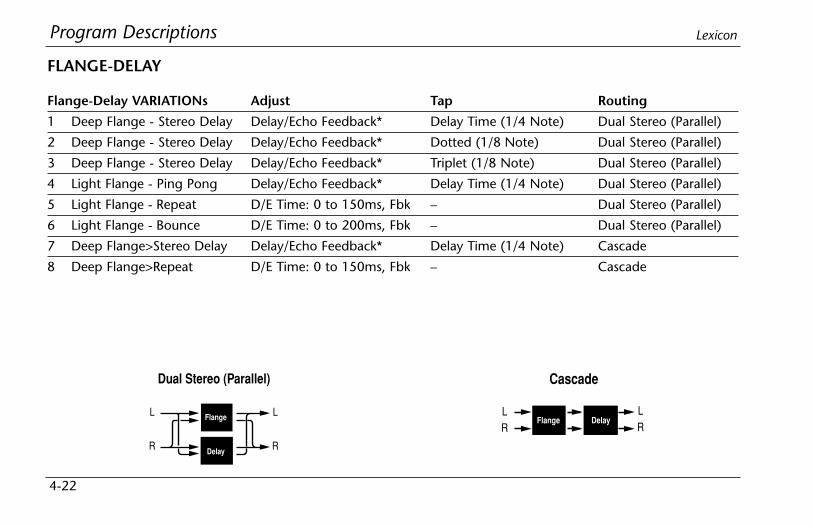
Flange-Delay VARIATIONs Adjust Tap Routing
1 Deep Flange - Stereo Delay Delay/Echo Feedback* Delay Time (1/4 Note) Dual Stereo (Parallel)
2 Deep Flange - Stereo Delay Delay/Echo Feedback* Dotted (1/8 Note) Dual Stereo (Parallel)
3 Deep Flange - Stereo Delay Delay/Echo Feedback* Triplet (1/8 Note) Dual Stereo (Parallel)
4 Light Flange - Ping Pong Delay/Echo Feedback* Delay Time (1/4 Note) Dual Stereo (Parallel)
5 Light Flange - Repeat D/E Time: 0 to 150ms, Fbk – Dual Stereo (Parallel)
6 Light Flange - Bounce D/E Time: 0 to 200ms, Fbk – Dual Stereo (Parallel)
7 Deep Flange>Stereo Delay Delay/Echo Feedback* Delay Time (1/4 Note) Cascade
8 Deep Flange>Repeat D/E Time: 0 to 150ms, Fbk – Cascade
FLANGE-DELAY
Dual Stereo (Parallel)
Flange
Delay
L
R
L
R
Cascade
Flange DelayLR
LR

Program DescriptionsMPX 110
4-23
Flange-Delay VARIATIONs Adjust Tap Routing
9 Deep Flange>Ping Pong Delay/Echo Feedback* Delay Time (1/4 Note) Cascade
10 Deep Flange>Bounce D/E Time: 0 to 200ms, Fbk – Cascade
11 Light Flange+Stereo Delay Delay/Echo Feedback* Delay Time (1/4 Note) Mono Split
12 Light Flange+Ping Pong Delay/Echo Feedback* Delay Time (1/4 Note) Mono Split
13 Light Flange+Repeat D/E Time: 0 to 150ms, Fbk – Mono Split
14 Light Flange+Bounce D/E Time: 0 to 200ms, Fbk – Mono Split
15 Deep Flange/Mono Delay Delay/Echo Feedback* Delay Time (1/4 Note) Dual Mono
16 Deep Flange/Mono Delay Delay/Echo Feedback* Dly Time (Dotted 1/4 Note) Dual Mono* In these variations, the Adjust knob functions as it does in the Delay, Echo variations. See page 2-2 for more information.
Mono Split
Flange
Delay
L
R
L
R
Dual Mono
Flange
Delay
L
R
L
R
Program Descriptions Lexicon
4-24
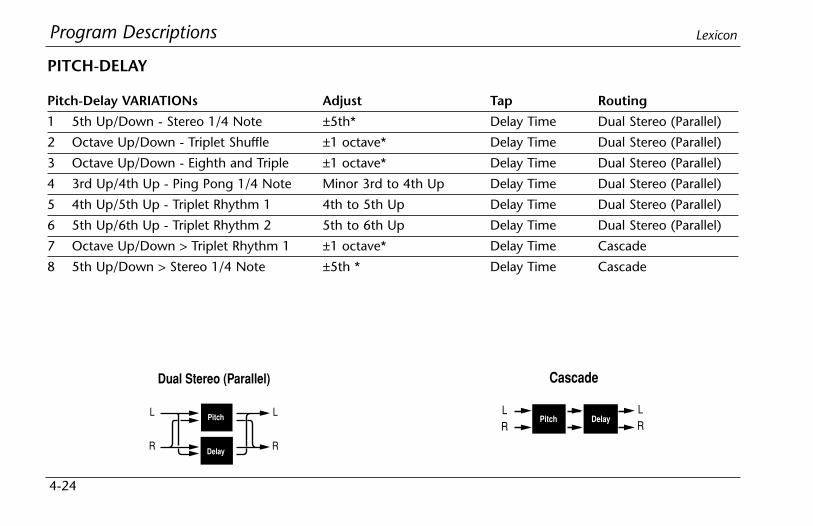
Pitch-Delay VARIATIONs Adjust Tap Routing
1 5th Up/Down - Stereo 1/4 Note ±5th* Delay Time Dual Stereo (Parallel)
2 Octave Up/Down - Triplet Shuffle ±1 octave* Delay Time Dual Stereo (Parallel)
3 Octave Up/Down - Eighth and Triple ±1 octave* Delay Time Dual Stereo (Parallel)
4 3rd Up/4th Up - Ping Pong 1/4 Note Minor 3rd to 4th Up Delay Time Dual Stereo (Parallel)
5 4th Up/5th Up - Triplet Rhythm 1 4th to 5th Up Delay Time Dual Stereo (Parallel)
6 5th Up/6th Up - Triplet Rhythm 2 5th to 6th Up Delay Time Dual Stereo (Parallel)
7 Octave Up/Down > Triplet Rhythm 1 ±1 octave* Delay Time Cascade
8 5th Up/Down > Stereo 1/4 Note ±5th * Delay Time Cascade
PITCH-DELAY
Dual Stereo (Parallel)
Pitch
Delay
L
R
L
R
Cascade
Pitch DelayLR
LR
Program DescriptionsMPX 110
4-25
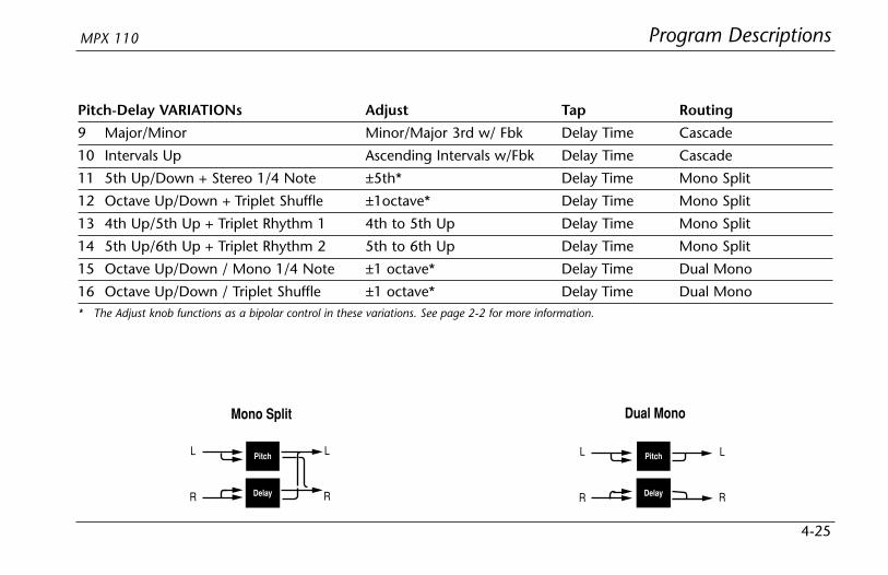
Pitch-Delay VARIATIONs Adjust Tap Routing
9 Major/Minor Minor/Major 3rd w/ Fbk Delay Time Cascade
10 Intervals Up Ascending Intervals w/Fbk Delay Time Cascade
11 5th Up/Down + Stereo 1/4 Note ±5th* Delay Time Mono Split
12 Octave Up/Down + Triplet Shuffle ±1octave* Delay Time Mono Split
13 4th Up/5th Up + Triplet Rhythm 1 4th to 5th Up Delay Time Mono Split
14 5th Up/6th Up + Triplet Rhythm 2 5th to 6th Up Delay Time Mono Split
15 Octave Up/Down / Mono 1/4 Note ±1 octave* Delay Time Dual Mono
16 Octave Up/Down / Triplet Shuffle ±1 octave* Delay Time Dual Mono* The Adjust knob functions as a bipolar control in these variations. See page 2-2 for more information.
Mono Split
Pitch
Delay
L
R
L
R
Dual Mono
Pitch
Delay
L
R
L
R

Program Descriptions Lexicon
4-26
Chorus-Delay VARIATIONs Adjust Tap Routing
1 Rich Chorus 1 - Stereo 1/4 Note Delay/Echo Feedback* Delay Time Dual Stereo (Parallel)
2 Rich Chorus 1 - Dotted 1/8 Note Delay/Echo Feedback* Delay Time Dual Stereo (Parallel)
3 Rich Chorus 1 - 1/8 Note and Triplet Delay/Echo Feedback* Delay Time Dual Stereo (Parallel)
4 Rich Chorus 1 - Ping Pong 1/4 Note Delay/Echo Feedback* Delay Time Dual Stereo (Parallel)
5 Rich Chorus 1 - Multi Repeat D/E Time: 0 to 150ms, Fbk – Dual Stereo (Parallel)
6 Rich Chorus 1 - Multi Pong D/E Time: 0 to 200ms, Fbk – Dual Stereo (Parallel)
7 Rich Chorus 1 > Stereo 1/4 Note Delay/Echo Feedback* Delay Time Cascade
8 Rich Chorus 2 > Multi Repeat D/E Time: 0 to 150ms, Fbk – Cascade
CHORUS-DELAY
Dual Stereo (Parallel)
Chorus
Delay
L
R
L
R
Cascade
Chorus DelayLR
LR

Program DescriptionsMPX 110
4-27
Chorus-Delay VARIATIONs Adjust Tap Routing
9 Rich Chorus 2 > Ping Pong 1/4 Note Delay/Echo Feedback* Delay Time Cascade
10 Rich Chorus 3 > Multi Pong D/E Time: 0 to 200ms, Fbk – Cascade
11 Rich Chorus 1 + Stereo 1/4 Note Delay/Echo Feedback* Delay Time Mono Split
12 Rich Chorus 1 + Ping Pong 1/4 Note Delay/Echo Feedback* Delay Time Mono Split
13 Rich Chorus 1 + Crossfeed D/E Time: 0 to 150ms, Fbk – Mono Split
14 Rich Chorus 1 + Multi Pong D/E Time: 0 to 200ms, Fbk – Mono Split
15 Rich Chorus 4 Mono 1/4 Note Delay/Echo Feedback* Delay Time Dual Mono
16 Rich Chorus 4 Dotted 1/8 Note Delay/Echo Feedback* Delay Time Dual Mono* The Adjust knob functions as a bipolar control in these variations. See page 2-2 for more information.
Mono Split
Chorus
Delay
L
R
L
R
Dual Mono
Chorus
Delay
L
R
L
R

Program Descriptions Lexicon
4-28
Delay-Reverb VARIATIONs Adjust* Tap Routing
1 Stereo 1/4 Note - Small Space Decay Time Delay Time Dual Stereo (Parallel)
2 Triplet Shuffle - Medium Space Decay Time Delay Time Dual Stereo (Parallel)
3 1/8 Note and Triplet - Large Space Decay Time Delay Time Dual Stereo (Parallel)
4 Ping Pong 1/4 Note - Small Space Decay Time Delay Time Dual Stereo (Parallel)
5 Triplet Rhythm 1 - Medium Space Decay Time Delay Time Dual Stereo (Parallel)
6 Triplet Rhythm 2 - Large Space Decay Time Delay Time Dual Stereo (Parallel)
7 Stereo 1/4 Note > Room Decay Time Delay Time Cascade
8 1/8 Note and Triplet > Large Space Decay Time Delay Time Cascade
DELAY-REVERB
Dual Stereo (Parallel)
Delay
Reverb
L
R
L
R
Cascade
Delay ReverbLR
LR

Program DescriptionsMPX 110
4-29
Delay-Reverb VARIATIONs Adjust* Tap Routing
9 Triplet Rhythm 1 > Room Decay Time Delay Time Cascade
10 Triplet Rhythm 2 > Large Space Decay Time Delay Time Cascade
11 Stereo 1/4 Note + Medium Space Decay Time Delay Time Mono Split
12 Ping Pong 1/4 Note + Large Space Decay Time Delay Time Mono Split
13 Triplet Rhythm 1 + Medium Space Decay Time Delay Time Mono Split
14 Triplet Rhythm 2 + Small Space Decay Time Delay Time Mono Split
15 Mono 1/4 Note / Room Decay Time Delay Time Dual Mono
16 Triplet Rhythm 2 / Large Space Decay Time Delay Time Dual Mono* The Adjust knob functions as a linear control in these variations. See page 2-2 for more information.
Mono Split
Delay
Reverb
L
R
L
R
Dual Mono
Delay
Reverb
L
R
L
R

Program Descriptions Lexicon
4-30
Flange-Reverb VARIATIONs Adjust* Tap Routing
1 Light Flange - Small Space Decay Time Speed Dual Stereo (Parallel)
2 Light Flange - Medium Space Decay Time – Dual Stereo (Parallel)
3 Light Flange - Large Space Decay Time Speed Dual Stereo (Parallel)
4 Deep Flange - Small Space Decay Time – Dual Stereo (Parallel)
5 Deep Flange - Medium Space Decay Time Speed Dual Stereo (Parallel)
6 Deep Flange - Large Space Decay Time Speed Dual Stereo (Parallel)
7 Light Flange - Large Space Decay Time – Cascade
8 Deep Flange - Large Space Decay Time – Cascade
FLANGE-REVERB
Dual Stereo (Parallel)
Flange
Reverb
L
R
L
R
Cascade
Flange ReverbLR
LR
Program DescriptionsMPX 110
4-31
Flange-Reverb VARIATIONs Adjust* Tap Routing
9 Light Flange > Room Decay Time – Cascade
10 Deep Flange > Room Decay Time Speed Cascade
11 Light Flange + Medium Space Decay Time Speed Mono Split
12 Light Flange + Room Decay Time Speed Mono Split
13 Deep Flange + Medium Space Decay Time Speed Mono Split
14 Deep Flange + Room Decay Time – Mono Split
15 Light Flange / Large Space Decay Time Speed Dual Mono
16 Light Flange / Large Space Decay Time – Dual Mono* The Adjust knob functions as a linear control in these variations. See page 2-2 for more information.
Mono Split
Flange
Reverb
L
R
L
R
Dual Mono
Flange
Reverb
L
R
L
R

Program Descriptions Lexicon
4-32
Pitch-Reverb VARIATIONs Adjust Tap Routing
1 Minor 3rd to 4th - Room 3rd to 4th Up PreDelay (1/32 Note) Dual Stereo (Parallel)
2 4th to 5th - Room 4th to 5th Up PreDelay (1/32 Note) Dual Stereo (Parallel)
3 5th to 6th - Room 5th to 6th Up PreDelay (1/32 Note) Dual Stereo (Parallel)
4 ±1 Octave - Medium Space ±1 Octave* PreDelay (1/32 Note) Dual Stereo (Parallel)
5 Power Chords - Medium Space Decay Time PreDelay (1/32 Note) Dual Stereo (Parallel)
6 Manual Detune - Room Detuning PreDelay (1/32 Note) Dual Stereo (Parallel)
7 ±100 > Small Space ±100 Cents* PreDelay (1/32 Note) Cascade
8 Power Chords > Large Space Decay Time PreDelay (1/32 Note) Cascade
PITCH-REVERB
Dual Stereo (Parallel)
Pitch
Reverb
L
R
L
R
Cascade
Pitch ReverbLR
LR

Program DescriptionsMPX 110
4-33
Pitch-Reverb VARIATIONs Adjust Tap Routing
9 4ths > Medium Space Decay Time PreDelay (1/32 Note) Cascade
10 Octaves > Medium Space Decay Time PreDelay (1/32 Note) Cascade
11 4th to 5th + Room 4th to 5th Up PreDelay (1/32 Note) Mono Split
12 5th to 6th + Room 5th to 6th Up PreDelay (1/32 Note) Mono Split
13 4ths + Large Space Decay Time PreDelay (1/32 Note) Mono Split
14 Octaves + Medium Space Decay Time PreDelay (1/32 Note) Mono Split
15 Octaves / Medium Space Decay Time PreDelay (1/32 Note) Dual Mono
16 4ths / Large Space Decay Time PreDelay (1/32 Note) Dual Mono
* The Adjust knob functions as a bipolar control in these variations. See page 2-2 for more information.
Mono Split
Pitch
Reverb
L
R
L
R
Dual Mono
Pitch
Reverb
L
R
L
R

Program Descriptions Lexicon
4-34
Chorus-Reverb VARIATIONs Adjust* Tap Routing
1 Rich Chorus 1 - Small Space Decay Time – Dual Stereo (Parallel)
2 Rich Chorus 1 - Medium Space Decay Time – Dual Stereo (Parallel)
3 Rich Chorus 1 - Large Space Decay Time – Dual Stereo (Parallel)
4 Rich Chorus 2 - Small Space Decay Time – Dual Stereo (Parallel)
5 Rich Chorus 2 - Medium Space Decay Time – Dual Stereo (Parallel)
6 Rich Chorus 2 - Large Space Decay Time – Dual Stereo (Parallel)
7 Rich Chorus 1 > Room Liveness – Cascade
8 Rich Chorus 2 > Room Liveness – Cascade
CHORUS-REVERB
Dual Stereo (Parallel)
Chorus
Reverb
L
R
L
R
Cascade
Chorus ReverbLR
LR
Program DescriptionsMPX 110
4-35
Chorus-Reverb VARIATIONs Adjust* Tap Routing
9 Rich Chorus 3 > Room Liveness – Cascade
10 Rich Chorus 1 > Small Space Decay Time – Cascade
11 Rich Chorus 1 + Small Space Decay Time – Mono Split
12 Rich Chorus 2 + Medium Space Decay Time – Mono Split
13 Rich Chorus 2 + Large Space Decay Time – Mono Split
14 Rich Chorus 1 + Large Space Decay Time – Mono Split
15 Rich Chorus 1 / Room Liveness – Dual Mono
16 Rich Chorus 4 / Room Liveness – Dual Mono* The Adjust knob functions as a linear control in these variations. See page 2-2 for more information.
Mono Split
Chorus
Reverb
L
R
L
R
Dual Mono
Chorus
Reverb
L
R
L
R

Program Descriptions Lexicon
4-36
THE PITCH PROGRAMSThe MPX 110 features single Pitch, Pitch-Delay, andPitch-Reverb programs. All pitch programs are designedto input and output two channels and to respond topitch-shifting in either Stereo or Dual Mono mode.
Note:In this case, Dual Mono refers to signal type - notrouting configuration.
In Stereo mode, the same pitch-shift is applied to bothchannels at the same time. This helps maintain theproper phase relationship between the channels. Whenpitch programs operate in Stereo mode, rotating theAdjust knob will affect both channels in the samemanner.
In Dual Mono mode, pitch-shift is applied to eachchannel separately. When pitch programs operate inDual Mono mode, rotating the Adjust knob will affecteach channel in a different manner. Sometimes onechannel may seem to experience no effect at all.
The mode in which a particular program responds topitch-shifting cannot be selected. The tables that beginbelow list each pitch program along with its assignedmode of operation.
Pitch VARIATIONs
1 Semi-tone Shift Stereo
2 Glide Shifter Stereo
3 ±100 cents Stereo
4 Minor 3rd to 4th Harmony Stereo
5 4th/5th Harmony Stereo
6 5th/6th Harmony Stereo
7 2nd Inversion Triad Dual Mono
8 Power Chords Dual MonoFor more information about Pitch VARIATIONs, see page 4-14.
Program DescriptionsMPX 110
4-37
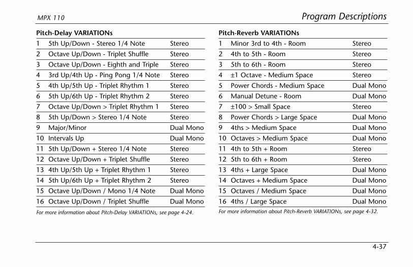
Pitch-Delay VARIATIONs
1 5th Up/Down - Stereo 1/4 Note Stereo
2 Octave Up/Down - Triplet Shuffle Stereo
3 Octave Up/Down - Eighth and Triple Stereo
4 3rd Up/4th Up - Ping Pong 1/4 Note Stereo
5 4th Up/5th Up - Triplet Rhythm 1 Stereo
6 5th Up/6th Up - Triplet Rhythm 2 Stereo
7 Octave Up/Down > Triplet Rhythm 1 Stereo
8 5th Up/Down > Stereo 1/4 Note Stereo
9 Major/Minor Dual Mono
10 Intervals Up Dual Mono
11 5th Up/Down + Stereo 1/4 Note Stereo
12 Octave Up/Down + Triplet Shuffle Stereo
13 4th Up/5th Up + Triplet Rhythm 1 Stereo
14 5th Up/6th Up + Triplet Rhythm 2 Stereo
15 Octave Up/Down / Mono 1/4 Note Dual Mono
16 Octave Up/Down / Triplet Shuffle Dual Mono
For more information about Pitch-Delay VARIATIONs, see page 4-24.
Pitch-Reverb VARIATIONs
1 Minor 3rd to 4th - Room Stereo
2 4th to 5th - Room Stereo
3 5th to 6th - Room Stereo
4 ±1 Octave - Medium Space Stereo
5 Power Chords - Medium Space Dual Mono
6 Manual Detune - Room Dual Mono
7 ±100 > Small Space Stereo
8 Power Chords > Large Space Dual Mono
9 4ths > Medium Space Dual Mono
10 Octaves > Medium Space Dual Mono
11 4th to 5th + Room Stereo
12 5th to 6th + Room Stereo
13 4ths + Large Space Dual Mono
14 Octaves + Medium Space Dual Mono
15 Octaves / Medium Space Dual Mono
16 4ths / Large Space Dual MonoFor more information about Pitch-Reverb VARIATIONs, see page 4-32.

Program Descriptions Lexicon
4-38
USER PROGRAMSWhen the PROGRAM knob is set to User, VARIATIONknob settings 1 to 16 each select one memory locationavailable for storing User programs. When shipped, theselocations will contain duplicates of preset programs. Thetable at the right lists the factory-default preset stored ineach User memory location.
VARIATION Preset
1 Medium Plate (Plate 2)
2 Straight Gate (Gate 9)
3 Synth Hall (Hall 5)
4 Medium Hall (Hall 6)
5 Percussion 2 (Chamber 13)
6 Small Ambience (Ambience 3)
7 Rehearsal Room (Room 14)
8 Rectified Sine Wave (Tremolo 1)
9 Rotary (Rotary 9)
10 Tap Rotary (Rotary 15)
11 Rich Chorus (Chorus 3)
12 Light Flange: out of phase sweep(Flange 12)
13 Semi-tone Shift (Pitch 1)
14 FullRange (Detune 12)
15 Triplet Rhythm 2 (Delay, Echo 8)
16 Multi Bounce (Delay, Echo 12)

MIDI Operation
5Learn Mode .....................................................................................5-2
Program Load Channel....................................................................5-3
Program Change Messages .............................................................5-4Loading Programs • Activating Bypass or Tap Functions
Learning Continuous Controllers .....................................................5-6
Clearing Learned Assignments .........................................................5-7
MIDI Clock ......................................................................................5-8
MIDI Dumps....................................................................................5-8
MIDI Sysex Messages.......................................................................5-9
Permanent Patches ..........................................................................5-9
MIDI Implementation Chart...........................................................5-12

MIDI Operation Lexicon
5-2
LEARN MODELearn Mode enables the MPX 110 to “learn” MIDI Program Change andContinuous Controller messages. To activate and deactivate Learn Mode, pressthe Store and Tap buttons simultaneously. The Store LED will flash slowly and theTap LED will light to indicate that Learn Mode is active.
The unit supports five learned patches for the front panel Mix, Effects Lvl/Bal,Adjust, Bypass, and Tap controls. Program Change messages 0 to 15 are reservedfor executing program loads. The Program Load function can also be assigned toa separate MIDI channel (see page 5-3).
These controls can bepatched to ContinuousController messages.
These controls can alsobe patched to ProgramChange messages.
Program Change messages canbe used to load programs.
Simultaneously press theStore and Tap buttons toactivate and deactivateLearn Mode.
MIDI OperationMPX 110
5-3
PROGRAM LOAD CHANNELThe MPX 110 is designed to have one MIDI channeldedicated to loading programs, called the Program LoadMIDI Channel. This allows Program Change messages toload programs.
The Program Load channel can be the same channel thatis used to receive other Program Change messages forLearned Patches. However, numbers 0 to 15 will alwaysload the 16 variations of the selected program. ProgramChange messages 0 to 15 will be ignored on all otherMIDI channels.
MIDI channel 1 is the default Program Load Channel. Toassign this function to a different channel:
1. Simultaneously press the Store and Tap buttonsto activate Learn Mode. The Store LED will flashslowly and the Tap LED will light to indicate thatLearn Mode is active.
2. Send a Program Change message to the unit. TheEdit LED will flash to indicate incoming MIDI activity.
3. The unit learns the MIDI channel of the transmittingdevice, and reassigns the Program Load function tothat channel.
4. Simultaneously press the Store and Tap buttonsto deactivate Learn Mode.
The unit will remember the Program Load Channelassignment until the Program Load Channel isreassigned using the same procedure.
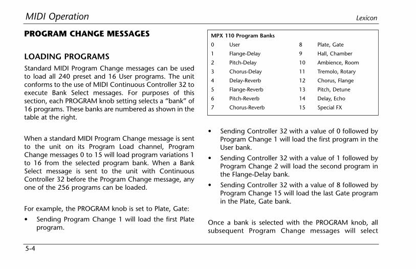
MIDI Operation Lexicon
5-4
PROGRAM CHANGE MESSAGES
LOADING PROGRAMSStandard MIDI Program Change messages can be usedto load all 240 preset and 16 User programs. The unitconforms to the use of MIDI Continuous Controller 32 toexecute Bank Select messages. For purposes of thissection, each PROGRAM knob setting selects a “bank” of16 programs. These banks are numbered as shown in thetable at the right.
When a standard MIDI Program Change message is sentto the unit on its Program Load channel, ProgramChange messages 0 to 15 will load program variations 1to 16 from the selected program bank. When a BankSelect message is sent to the unit with ContinuousController 32 before the Program Change message, anyone of the 256 programs can be loaded.
For example, the PROGRAM knob is set to Plate, Gate:
• Sending Program Change 1 will load the first Plateprogram.
• Sending Controller 32 with a value of 0 followed byProgram Change 1 will load the first program in theUser bank.
• Sending Controller 32 with a value of 1 followed byProgram Change 2 will load the second program inthe Flange-Delay bank.
• Sending Controller 32 with a value of 8 followed byProgram Change 15 will load the last Gate programin the Plate, Gate bank.
Once a bank is selected with the PROGRAM knob, allsubsequent Program Change messages will select
MPX 110 Program Banks
0 User
1 Flange-Delay
2 Pitch-Delay
3 Chorus-Delay
4 Delay-Reverb
5 Flange-Reverb
6 Pitch-Reverb
7 Chorus-Reverb
8 Plate, Gate
9 Hall, Chamber
10 Ambience, Room
11 Tremolo, Rotary
12 Chorus, Flange
13 Pitch, Detune
14 Delay, Echo
15 Special FX

MIDI OperationMPX 110
5-5
programs within that bank until a new value forController 32 is received, or until the PROGRAM orVARIATION knobs are adjusted.
MIDI Program Change messages can be disabled inSystem Mode with the MIDI Pgm Change parameter(see page 3-4 for more information).
ACTIVATING BYPASS OR TAP FUNCTIONSThe unit can recognize MIDI Program Change messages16 to 127 (17 to 128 on some MIDI devices) on anychannels.
To assign a Program Change message to the Bypass orTap controls:
1. Simultaneously press the Store and Tap buttonsto activate Learn mode. The Store LED will flashslowly and the Tap LED will light to indicate thatLearn Mode is active.
2. Press the desired front panel button - Bypass or Tap.
3. Send a MIDI Program Change message to the MPX110. The Edit LED will flash to indicate incomingMIDI activity.
4. Press the Store button to commit the assignment.The Store LED will flash repeatedly.
5. Simultaneously press the Store and Tap buttonsto deactivate Learn Mode.
Some MIDI controllers do not allow repeated ProgramChange messages to be sent with a single button. Toassist these controllers, the unit also recognizes the nexthighest Program Change message with each ProgramChange message it learns for Bypass and Tap. Forinstance, if Program Change 20 is learned as the sourcefor Bypass, Program Change 21 will also control Bypassfunctions. To avoid conflicting Bypass and Tapassignments, leave a space between the assignments ofthese two buttons. For instance, if Program Change 20 islearned for Bypass, remember that 21 will also belearned. Skip to Program Change 22 (and consequently23) for Tap.

MIDI Operation Lexicon
5-6
LEARNING CONTINUOUS CONTROLLERSThe unit recognizes Pitch Bend, AfterTouch, and MIDIContinuous Controllers 1 to 31 and 33 to 119.
To learn a Continuous Controller:
1. Simultaneously press the Store and Tap buttonsto activate Learn mode. The Store LED will flashslowly and the Tap LED will light to indicate thatLearn Mode is active.
2. Adjust the desired front panel control - Mix, EffectsLvl/Bal, Adjust, Bypass, or Tap - to assign it to thecontroller.
3. Move the MIDI controller through its full range. Toutilize a portion of the controller range, limit thismovement to the desired range. The Edit LED willflash to indicate incoming MIDI activity.
4. Press the Store button to commit to the assignment.The Store LED will flash quickly.
5. To assign another front panel control, repeat steps 2to 4.
6. Simultaneously press the Store and Tap buttonsto deactivate Learn Mode.
Note:When a MIDI controller has been assigned to theBypass control, moving the controller above themid-point of its learned range engages Bypass.Moving the controller below the mid-point rangedisengages Bypass. When a MIDI controller hasbeen assigned to the Tap control, moving thecontroller above the mid-point of its learned rangewill “tap” the control as if the Tap button had beenpressed.
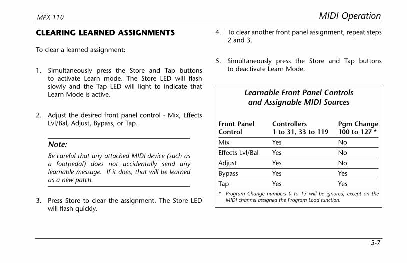
MIDI OperationMPX 110
5-7
CLEARING LEARNED ASSIGNMENTS
To clear a learned assignment:
1. Simultaneously press the Store and Tap buttonsto activate Learn mode. The Store LED will flashslowly and the Tap LED will light to indicate thatLearn Mode is active.
2. Adjust the desired front panel control - Mix, EffectsLvl/Bal, Adjust, Bypass, or Tap.
Note:Be careful that any attached MIDI device (such asa footpedal) does not accidentally send anylearnable message. If it does, that will be learnedas a new patch.
3. Press Store to clear the assignment. The Store LEDwill flash quickly.
4. To clear another front panel assignment, repeat steps2 and 3.
5. Simultaneously press the Store and Tap buttonsto deactivate Learn Mode.
Learnable Front Panel Controlsand Assignable MIDI Sources
Front Panel Controllers Pgm ChangeControl 1 to 31, 33 to 119 100 to 127 *
Mix Yes No
Effects Lvl/Bal Yes No
Adjust Yes No
Bypass Yes Yes
Tap Yes Yes* Program Change numbers 0 to 15 will be ignored, except on the
MIDI channel assigned the Program Load function.

MIDI Operation Lexicon
5-8
MIDI CLOCKThe unit can use MIDI Clock messages to apply tempo(40 to 400bpm) to programs that use the Tap Tempofeature. Connect a MIDI device that outputs MIDI Clock,such as the MPX R1 foot controller or a MIDI sequencer,to the MPX 110 MIDI IN connector. The unit willautomatically recognize and begin to process MIDI Clockmessages. When the tempo of the connected devicechanges, the unit will automatically adjust its delay timesand modulation rates to match the new tempo.
This feature can be disabled with the MIDI Clock Receiveparameter in System Mode (see page 3-5).
MIDI DUMPSMIDI Dumps can be used to save the 16 User programs,the currently active program, or the System Modesettings and Learned Patch assignments to a storagedevice (typically a MIDI sequencer). MIDI Dumps areperformed in System Mode.
To perform a MIDI Dump:
1. Press and hold the Bypass button for 2 seconds. TheBypass and Store LEDs will blink to indicate thatSystem Mode is active.
2. Set the VARIATION knob to 14 to dump the Userprograms; 15 to dump the currently active (orloaded) program; or 16 to dump the System Modesettings and Learned Patch assignments.
3. Press Store to execute the dump.
4. Press Bypass to deactivate System Mode.

MIDI OperationMPX 110
5-9
MIDI SYSEX MESSAGESMIDI Sysex messages can be used to access all algorithmparameters. More information about using this advancedfeature with the MPX 110 and other Lexicon products isavailable at www.lexicon.com. The website offersinstructions, sample messages, and a complete table ofparameter Sysex addresses.
Note:Executing MIDI Sysex messages is a complicatedprocess. Please observe the cautionary notesincluded on the website.
PERMANENT PATCHESThe MPX 110 recognizes permanent, non-learnableMIDI patches to provide additional MIDI control.Permanent patches connect designated ContinuousControllers to specific audio parameters that are notaccessible on the front panel. Permanent Patches foreach algorithm are shown on pages 5-10 and 5-11.
The unit recognizes Permanent Patches on the currentProgram Load Channel only. To use a permanentlypatched controller for a Learned Patch, make the unitlearn that patch on a different channel. If a controller isused for both a Permanent and Learned Patch on thesame channel, the result will be unpredictable.
Some patched parameters are also controlled with theAdjust knob. In these cases, either control will functionand will override adjustments made by the other.
Note:Permanent Patches will be disabled when the SystemMode parameter MIDI Patching is set to Disabled.

CCNo. Plate Gate Hall Chamber Ambience Room Tremolo Rotary Chorus Flange
1 Decay Duration Decay Decay DecayTime Decay Rate MstrRate KorRate1 FlgRate
2 PreDelay PreDelay PreDelay PreDelay PreDelay PreDelay Depth MstrDepth KorRate2 FlgDepth
3 RTHiCut LowSlope RTHiCut RTHiCut RTHiCut RTHiCut Phase Resnce1 KorDepth1 FlgResnce
4 Bassmult HighSlope Bassmult Bassmult DecayLvl Bassmult Waveform Resnce2 KorDepth2 FlgBlend
5 Bassxover Crossover Bassxover Bassxover – Bassxover – Width KorResnce1 –
6 – RTHiCut – – – – – – KorResnce2 –
7 Rolloff Rolloff Rolloff Rolloff Rolloff Rolloff Rolloff Rolloff KorSpread Rolloff
8 – – – – – – – – Rolloff –
CC Special FX VARIATION 5:No. Rotary Delay
1 MstrRate
2 MstrDepth
3 Resnce1
4 Resnce2
5 Width
6 MstrDly
7 RTHiCut
8 DlyHiCut
MIDI Operation Lexicon
5-10
Permanent Patches (continued)
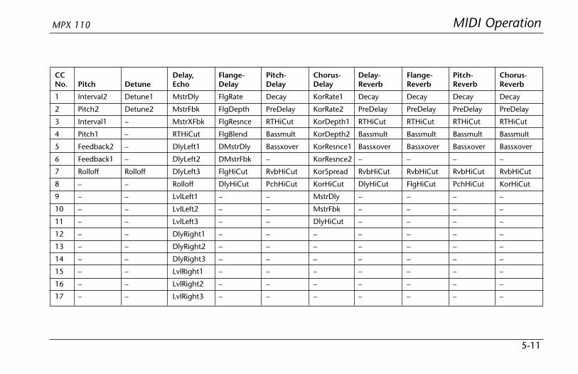
MIDI OperationMPX 110
5-11
CC Delay, Flange- Pitch- Chorus- Delay- Flange- Pitch- Chorus-No. Pitch Detune Echo Delay Delay Delay Reverb Reverb Reverb Reverb
1 Interval2 Detune1 MstrDly FlgRate Decay KorRate1 Decay Decay Decay Decay
2 Pitch2 Detune2 MstrFbk FlgDepth PreDelay KorRate2 PreDelay PreDelay PreDelay PreDelay
3 Interval1 – MstrXFbk FlgResnce RTHiCut KorDepth1 RTHiCut RTHiCut RTHiCut RTHiCut
4 Pitch1 – RTHiCut FlgBlend Bassmult KorDepth2 Bassmult Bassmult Bassmult Bassmult
5 Feedback2 – DlyLeft1 DMstrDly Bassxover KorResnce1 Bassxover Bassxover Bassxover Bassxover
6 Feedback1 – DlyLeft2 DMstrFbk – KorResnce2 – – – –
7 Rolloff Rolloff DlyLeft3 FlgHiCut RvbHiCut KorSpread RvbHiCut RvbHiCut RvbHiCut RvbHiCut
8 – – Rolloff DlyHiCut PchHiCut KorHiCut DlyHiCut FlgHiCut PchHiCut KorHiCut
9 – – LvlLeft1 – – MstrDly – – – –
10 – – LvlLeft2 – – MstrFbk – – – –
11 – – LvlLeft3 – – DlyHiCut – – – –
12 – – DlyRight1 – – – – – – –
13 – – DlyRight2 – – – – – – –
14 – – DlyRight3 – – – – – – –
15 – – LvlRight1 – – – – – – –
16 – – LvlRight2 – – – – – – –
17 – – LvlRight3 – – – – – – –
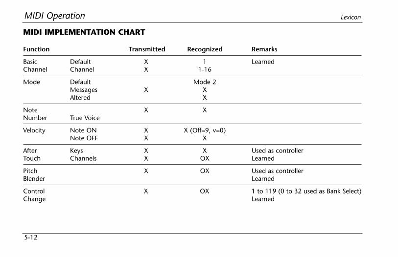
MIDI Operation Lexicon
5-12
Function Transmitted Recognized Remarks
Basic Default X 1 LearnedChannel Channel X 1-16
Mode Default Mode 2Messages X XAltered X
Note X XNumber True Voice
Velocity Note ON X X (Off=9, v=0)Note OFF X X
After Keys X X Used as controllerTouch Channels X OX Learned
Pitch X OX Used as controllerBlender Learned
Control X OX 1 to 119 (0 to 32 used as Bank Select)Change Learned
MIDI IMPLEMENTATION CHART

MIDI OperationMPX 110
5-13
Function Transmitted Recognized Remarks
Program X 0 to 15 = 1 to 16 16 to 127 ignored; Program ChangeChange True # messages 1 to 15 = Program Change
messages 1 to 16 for selectedBank Select X X program bank
System Lexicon O O Product ID = 14 (decimal)Exclusive Real Time X X Device ID = MIDI Channel 0 to15 =
non-Real Time X X 1 to 16
System :Song Pos X X:Song Sel X X
Common :Tune X X
System :Clock X OReal Time :Commands X X
Aux :Local ON/OFF X XMessages :All Notes OFF X X
:Active Sense:Reset X X
Mode 1: OMNI ON, POLY Mode 2: OMNI ON, MONO O: YesMode 3: OMNI OFF, POLY Mode 4: OMNI OFF, MONO X: No
OX: Selectable
Appendix
ASpecifications...................................................................................A-2
Declaration of Conformity ...............................................................A-3

Appendix Lexicon
A-2
Audio Inputs (2)Level -30dBu to +4dBuImpedance 500K unbalanced
1/4-inch connectors fordirect instrument input(unit detects a monoinput on the rightinput)
Audio Outputs (2)Level +8dBu typicalImpedance 75Ω 1/4-inch
connectors forheadphone output(right used for monooutput; left used forstereo headphones)
Digital Audio OutputConnector 24-bit digital S/PDIF
output (always active)Coaxial RCA
Sample Rate 44.1kHz
FootswitchTip/Ring/Sleeve phone jack for Bypassand Tap (optional)
Frequency ResponseWet/Dry 20Hz-20kHz, ±1dB
THD+N<0.05%, 20Hz-20kHz
Dynamic RangeA/A >95dB typical,
20Hz-20kHz,unweighted
A/D >100dB typical,20Hz-20kHz,unweighted
Conversion 24-bits analog-to-digital,24-bits digital-to-analog,44.1kHz sample rate
Crosstalk >45dB
Internal Audio Data PathDSP 24-bit
Power Requirements9VAC wall transformer provided in NorthAmerica and EuropeNo-transformer option available
DimensionsWidth 19 inches (483mm)Height 1.75 inches (45mm)Depth 4 inches (102mm)
Weight2 pounds, 2 ounces (0.959kg)
EnvironmentOperating 32 to 104°F (0 to 40°C)TemperatureRelative 95% Non-condensingHumidity
Specifications are subject to change without notice.
SPECIFICATIONS

AppendixMPX 110
A-3
DECLARATION OF CONFORMITY
Application of Council Directive(s): 89/336/EEC and 93/68/EEC
Standard(s) to which Conformity is Declared: EN 55103-1 and EN 55103-2
Manufacturer: Lexicon, Inc., 3 Oak Park, Bedford, MA 01730-1441 USAThe equipment identified here conforms to the Directive(s) andStandard(s) specified above.
Type of Equipment: Dual Channel Processor
Model: Lexicon MPX 110
Date: February 2002
Lexicon, Inc.Vice President of Engineering
3 Oak ParkBedford, MA 01730-1441 USA
Tel: 781-280-0300Fax: 781-280-0490

Index
IAdjust Knob . . . . . . . .1-5, 2-2, 2-4, 5-2, 5-7Ambience Programs . . . . . . . . . . .4-6, 5-10ANALOG INPUTs . . . . . . . . . . . . . . . . . .1-7ANALOG OUTPUTs . . . . . . . . . . . . . . . .1-7Appendix . . . . . . . . . . . . . . . . . .A-1 to A-3Audio Tap . . . . . . . . . . . . . . . . . . . . . . .2-5Bank Select Messages . . . . . . . . . . . . . . .5-4Basic Operation . . . . . . . . . . . . . .2-1 to 2-6Bypass Button . . .1-5, 2-6, 3-2, 5-2, 5-5, 5-7Bypass Functions . . . . . . . . . . . . . . . . . .2-6Bypass Parameter* . . . . . . . . . . . . . . . . .3-4Cascade Configuration . . . . . . . .4-20, 4-21CD-ROM, About the . . . . . . . . . . . . .iv to ixCD-ROM Dry Tracks . . . . . . . . . .Back CoverChamber Programs . . . . . . . . . . . .4-5, 5-10Chorus Programs . . . . . . . . . . . .4-12, 5-10Chorus-Delay Programs . .4-26 to 4-27, 5-11Chorus-Reverb Programs . .4-34 to 4-35, 5-11
Clearing Learned Assignments . . . . . . . .5-7Clip LEDs . . . . . . . . . . . . . . . . . . . . . . . .1-4Configuration, Routing . . . . . . . . . . . . .4-20Connecting the Unit . . . . . . . . . .1-8 to 1-9Connectors . . . . . . . . . . . . . . . . .1-6 to 1-7Continuous Controllers . . . . . . . . . . . . .5-6Declaration of Conformity . . . . . . . . . . .A-3Delay, Echo Programs . . . . . . . .4-16 to 4-17Delay-Reverb Programs . .4-28 to 4-29, 5-11Detune Programs . . . . . . . . . . . .4-15, 5-11Digital Output Parameter* . . . . . . . . . . .3-4Dry Tracks, CD-ROM . . . . . . . . . .Back CoverDual-Function Footswitch . . . . . . . . . . . .1-8Dual Mono Configuration . . . . . . . . . . .4-20Dual Mono Pitch Programs . . . .4-36 to 4-37DUAL Programs . . . . . . . .2-3, 4-20 to 4-35Dump Selected Program* . . . . . . . . . . . .3-5Dual Stereo (Parallel) Configuration . . . .4-20
Dump System and Learned Patches* . . . .3-5Dump User Programs* . . . . . . . . . . . . . .3-5Edit LED . . . . . . . . . . . . . . . . .1-5, 3-2, 3-3Editing Programs . . . . . . . . . . . . . . . . . .2-4Effects Lvl/Bal Knob . .1-5, 2-4, 4-21, 5-2, 5-7Factory-Default Settings, Restoring . . . .1-11Flange Programs . . . . . . . . . . . . .4-13, 5-10Flange-Delay Programs . .4-22 to 4-23, 5-11Flange-Reverb Programs . .4-30 to 4-31, 5-11Footswitch Connector . . . . . . . . . . . . . .1-6Footswitch, Connecting a . . . . . . . . . . . .1-8Front Panel . . . . . . . . . . . . . .1-4 to 1-5, 5-2Gate Programs . . . . . . . . . . . . . . .4-3, 5-10Getting Started . . . . . . . . . . . . .1-1 to 1-11Global Tempo . . . . . . . . . . . . . . . . . . . .2-6Hall Programs . . . . . . . . . . . . . . . .4-4, 5-10Headphones, Connecting . . . . . . . . . . . .1-8 Input Knob . . . . . . . . . . . . . . . . . . . . . .1-4
* Indicates System Mode Parameters and Functions.
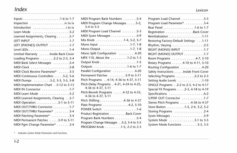
Index Lexicon
I-2
Inputs . . . . . . . . . . . . . . . . . . . .1-6 to 1-7Inspection . . . . . . . . . . . . . . . . . . .iv to ixIntroduction . . . . . . . . . . . . . . . . . .i to ixLearn Mode . . . . . . . . . . . . . . . . . . . .5-2Learned Assignments, Clearing . . . . . . .5-7LEFT INPUT . . . . . . . . . . . . . . . . . . . . .1-7LEFT (PHONES) OUTPUT . . . . . . . . . . .1-7Level LEDs . . . . . . . . . . . . . . . . . . . . . .1-4Limited Warranty . . . . . .Inside Back CoverLoading Programs . . . . . . .2-2 to 2-3, 5-4MIDI Bank Select Messages . . . . . . . . .5-4MIDI Clock . . . . . . . . . . . . . . . . . . . . .5-8MIDI Clock Receive Parameter* . . . . . .3-5MIDI Continuous Controllers . . . . .5-2, 5-6MIDI Dumps . . . . . . . . .3-2, 3-3, 3-5, 5-8MIDI Implementation Chart . .5-12 to 5-13MIDI IN Connector . . . . . . . . . . . . . . .1-7MIDI Learn Mode . . . . . . . . . . . . . . . .5-2MIDI Learned Assignments, Clearing . .5-7MIDI Operation . . . . . . . . . . . .5-1 to 5-11MIDI OUT/THRU Connector . . . . . . . . .1-7MIDI OUT/THRU Parameter* . . . . . . . .3-4MIDI Patching Parameter* . . . . . . . . . .3-4MIDI Permanent Patches . . . . .5-9 to 5-11MIDI Pgm Change Parameter* . . . . . . .3-4
MIDI Program Bank Numbers . . . . . . .5-4MIDI Program Change Messages . . . . .5-2,
5-4 to 5-5MIDI Program Load Channel . . . . . . . .5-3MIDI Sysex Messages . . . . . . . . . . . . . .5-9Mix Knob . . . . . . . . . . . . . . .1-4, 5-2, 5-7Mono Input . . . . . . . . . . . . . . . . .1-7, 1-8Mono Output . . . . . . . . . . . . . . . .1-7, 1-8Mono Split Configuration . . . . . . . . .4-20MPX 110, About the . . . . . . . . .1-2 to 1-3Output Knob . . . . . . . . . . . . . . . . . . . .1-5Outputs . . . . . . . . . . . . . . . . . .1-6 to 1-7Parallel Configuration . . . . . . . . . . . .4-20Permanent Patches . . . . . . . . .5-9 to 5-11Pitch Programs . .4-14, 4-36 to 4-37, 5-11Pitch-Delay Programs . .4-21, 4-24 to 4-25,
4-36 to 4-37, 5-11Pitch-Reverb Programs . . . . .4-32 to 4-33,
4-36 to 4-37, 5-11Pitch Shifting . . . . . . . . . . . . .4-36 to 4-37Plate Programs . . . . . . . . . . . . . .4-2, 5-10POWER Switch . . . . . . . . . . . . . . . . . .1-6Product Registration . . . . . . . . .Back CoverProgram Bank Numbers . . . . . . . . . . . .5-4Program Change Messages . .5-2, 5-4 to 5-5PROGRAM Knob . . . . . . . . .1-5, 2-2 to 2-3
Program Load Channel . . . . . . . . . . . .5-3Program Load Parameter* . . . . . . . . . .3-4Rear Panel . . . . . . . . . . . . . . . . .1-6 to 1-7Registration . . . . . . . . . . . . . . .Back CoverReinitialization . . . . . . . . . . . . . . . . . .1-11Restoring Factory-Default Settings . . .1-11Rhythm, Varying . . . . . . . . . . . . . . . . .2-5RIGHT (MONO) INPUT . . . . . . . . . . . .1-7RIGHT (MONO) OUTPUT . . . . . . . . . . .1-7Room Programs . . . . . . . . . . . . .4-7, 5-10Rotary Programs . . . . . .4-10 to 4-11, 5-10Routing Configuration . . . . . . . . . . . .4-20Safety Instructions . . . . .Inside Front CoverSelecting Programs . . . . . . . . . .2-2 to 2-3Setting Audio Levels . . . . . . . . . . . . .1-10SINGLE Programs . .2-2 to 2-3, 4-2 to 4-17Special FX Programs . . . .2-3, 4-18 to 4-19Specifications . . . . . . . . . . . . . . . . . . .A-2S/PDIF OUT Connector . . . . . . . . . . . .1-7Stereo Pitch Programs . . . . . .4-36 to 4-37Store Button . . . . . . . . . .1-5, 2-4, 3-2, 5-2Storing Programs . . . . . . . . . . . . . . . .2-4Sysex Messages . . . . . . . . . . . . . . . . . .5-9System Mode . . . . . . . . . . . . . .3-1 to 3-5System Mode Functions . . . . . . . .3-3, 3-5
* Indicates System Mode Parameters and Functions.
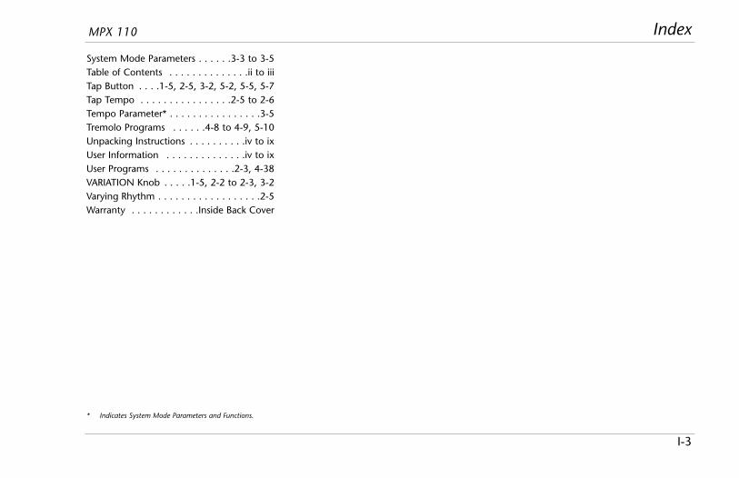
IndexMPX 110
I-3
System Mode Parameters . . . . . .3-3 to 3-5Table of Contents . . . . . . . . . . . . . .ii to iiiTap Button . . . .1-5, 2-5, 3-2, 5-2, 5-5, 5-7Tap Tempo . . . . . . . . . . . . . . . .2-5 to 2-6Tempo Parameter* . . . . . . . . . . . . . . . .3-5Tremolo Programs . . . . . .4-8 to 4-9, 5-10Unpacking Instructions . . . . . . . . . .iv to ixUser Information . . . . . . . . . . . . . .iv to ixUser Programs . . . . . . . . . . . . . .2-3, 4-38VARIATION Knob . . . . .1-5, 2-2 to 2-3, 3-2Varying Rhythm . . . . . . . . . . . . . . . . . .2-5Warranty . . . . . . . . . . . .Inside Back Cover
* Indicates System Mode Parameters and Functions.
NotesMPX 110

Notes Lexicon
LIMITED WARRANTY
Lexicon, Inc. offers the following warranty on this product:
What is the Duration of this Warranty?This warranty will remain in effect for one (1) year from the original date ofpurchase.
Who is Covered?This warranty may be enforced by the original purchaser and subsequentowners during the warranty period, provided the original dated sales receiptor other proof of warranty coverage is presented at time of service.
What is Covered?This warranty covers all defects in material and workmanship on this product,except as specified below. The following are not covered:1. Damage resulting from
A. Accident, misuse, abuse, or neglect.B. Failure to follow instructions contained in the User Guide.C. Repair or attempted repair unauthorized by Lexicon, Inc.D. Failure to perform recommended periodic maintenance.E. Causes other than product defects, including lack of skill,
competence, or experience on the part of the owner.2. Damage occurring during any shipment of this product. Claims for
shipping damages must be made with the carrier.3. Damage to a unit that has been altered, or on which the serial number
has been defaced, modified, or removed.
What Expenses will Lexicon, Inc. Assume?Lexicon, Inc. will pay all labor and material expenses for covered items.Payment of shipping charges is discussed in the next section of the warranty.
How is Service Obtained?When this product needs service, write, telephone, or fax Lexicon, Inc. torequest information about where the unit should be taken or sent. Whenmaking a written request, please include your name, complete address, and
daytime telephone number; the product model and serial numbers; and adescription of the problem. Do not return the unit to Lexicon, Inc. withoutprior authorization.
When Shipping a Product for Service . . .1. Pay any initial shipping charges, which are the responsibility of the
owner. If necessary repairs are covered by this warranty, Lexicon, Inc. willpay return shipping charges to any destination in the United States usingthe carrier of our choice.
2. Pack the unit securely. Package insurance is strongly recommended.3. Include a copy of the original dated sales receipt. (A copy of the original
dated sales receipt must be presented when warranty service is required.)4. Do not include accessories such as power cords or user guides unless
instructed to do so.
What are the Limitations of Implied Warranties?Any implied warranties, including warranties of merchantability and fitness fora particular purpose, are limited in duration to the length of this warranty.
What Certain Damages are Excluded?Lexicon’s liability for a defective product is limited to repair or replacement ofthat product, at our option. Lexicon, Inc. shall not be liable for damagesbased on inconvenience; loss of use of the product; loss of time; interruptedoperation; commercial loss; or any other damages, whether incidental,consequential, or otherwise.
How do State Laws Relate to this Warranty?Some states do not allow limitations on the duration of implied warrantiesand/or the exclusion or limitation of incidental or consequential damages. Assuch, the above limitations may not apply. This warranty is not enforceableoutside of North America. This warranty provides specific legal rights.Additional rights may be provided by some states.
A Harman International Company
Lexicon, Inc3 Oak ParkBedford, MA 01730-1441USA
Tel 781-280-0300Fax..781-280-0490
www.lexicon.com
Customer SupportTel 781-280-0300Fax..781-280-0495 (Sales)Fax..781-280-0499 (Service)

A Harman International Company
Lexicon Part No. 070-14956 | Rev 1 | 02/02
Lexicon, Inc.3 Oak ParkBedford, MA 01730-1441USA
Tel 781-280-0300Fax 781-280-0490
www.lexicon.com
Customer SupportTel 781-280-0300Fax 781-280-0495 (Sales)Fax 781-280-0499 (Service)

Percussion2 Bass Drum . . . . . . . . . . . . . . . . . . . . . .(0:30)3 Snare Drum 1 . . . . . . . . . . . . . . . . . . .(0:46)4 Snare Drum 2 . . . . . . . . . . . . . . . . . . .(0:38)5 Stick . . . . . . . . . . . . . . . . . . . . . . . . . .(0:38)6 Shaker . . . . . . . . . . . . . . . . . . . . . . . .(0:39)7 Claps . . . . . . . . . . . . . . . . . . . . . . . . .(0:41)8 Conga . . . . . . . . . . . . . . . . . . . . . . . .(0:48)9 Table & Udo . . . . . . . . . . . . . . . . . . . .(0:54)
10 Percussion 1 . . . . . . . . . . . . . . . . . . . .(1:00)11 Percussion 2 . . . . . . . . . . . . . . . . . . . .(1:23)12 Open Drum Kit . . . . . . . . . . . . . . . . . .(1:16)13 Funk Drum Kit . . . . . . . . . . . . . . . . . . .(1:08)14 Fusion Drums & Bass . . . . . . . . . . . . . .(0:33)15 Funk Drums & Bass . . . . . . . . . . . . . . .(0:33)16 Fusion Drums & Bass . . . . . . . . . . . . . .(1:18)17 Broadband Click . . . . . . . . . . . . . . . . .(0:38)18 Narrowband Click . . . . . . . . . . . . . . . .(0:38)
Guitar19 Acoustic Chords 1 . . . . . . . . . . . . . . . .(0:59)20 Acoustic Chords 2 . . . . . . . . . . . . . . . .(2:13)21 Acoustic Chords 3 . . . . . . . . . . . . . . . .(1:12)22 Acoustic Leads . . . . . . . . . . . . . . . . . . .(0:41)23 Acoustic Stops . . . . . . . . . . . . . . . . . . .(0:36)24 Electric Solo . . . . . . . . . . . . . . . . . . . .(0:44)25 Electric Clean & Fast . . . . . . . . . . . . . .(0:32)26 Electric Dirty . . . . . . . . . . . . . . . . . . . .(1:24)27 Electric Crunch . . . . . . . . . . . . . . . . . .(0:38)
Bass28 Slap (120 bpm) . . . . . . . . . . . . . . . . . .(1:29)29 Fingered (120 bpm) . . . . . . . . . . . . . .(0:49)
Do not play Track 1 on an audioCD player. It contains the computerportion of the disc and will emit full-scale digital noise.
Dry TracksThis card lists the dry tracks included on the CD-ROM enclosed with this user guide.
A Harman International Company
WARNING
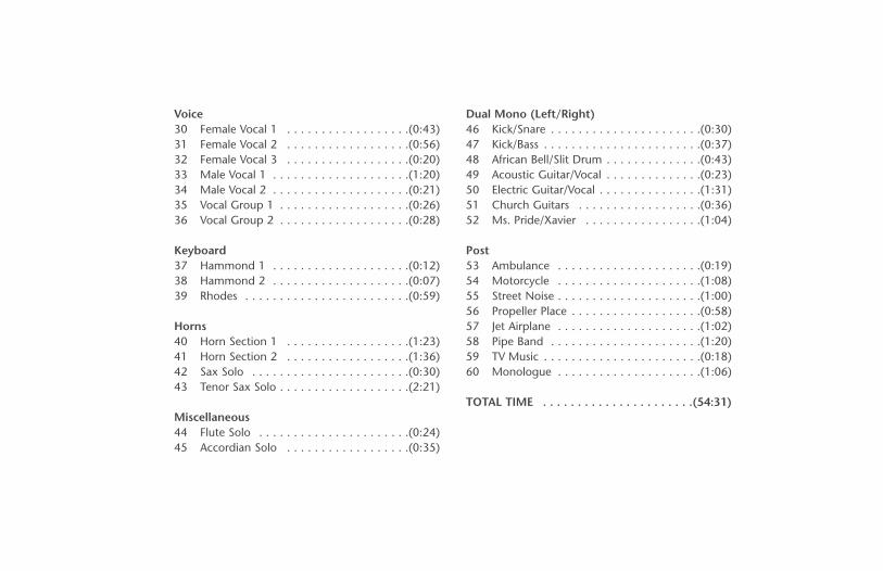
Voice30 Female Vocal 1 . . . . . . . . . . . . . . . . . .(0:43)31 Female Vocal 2 . . . . . . . . . . . . . . . . . .(0:56)32 Female Vocal 3 . . . . . . . . . . . . . . . . . .(0:20)33 Male Vocal 1 . . . . . . . . . . . . . . . . . . . .(1:20)34 Male Vocal 2 . . . . . . . . . . . . . . . . . . . .(0:21)35 Vocal Group 1 . . . . . . . . . . . . . . . . . . .(0:26)36 Vocal Group 2 . . . . . . . . . . . . . . . . . . .(0:28)
Keyboard37 Hammond 1 . . . . . . . . . . . . . . . . . . . .(0:12)38 Hammond 2 . . . . . . . . . . . . . . . . . . . .(0:07)39 Rhodes . . . . . . . . . . . . . . . . . . . . . . . .(0:59)
Horns40 Horn Section 1 . . . . . . . . . . . . . . . . . .(1:23)41 Horn Section 2 . . . . . . . . . . . . . . . . . .(1:36)42 Sax Solo . . . . . . . . . . . . . . . . . . . . . . .(0:30)43 Tenor Sax Solo . . . . . . . . . . . . . . . . . . .(2:21)
Miscellaneous44 Flute Solo . . . . . . . . . . . . . . . . . . . . . .(0:24)45 Accordian Solo . . . . . . . . . . . . . . . . . .(0:35)
Dual Mono (Left/Right)46 Kick/Snare . . . . . . . . . . . . . . . . . . . . . .(0:30)47 Kick/Bass . . . . . . . . . . . . . . . . . . . . . . .(0:37)48 African Bell/Slit Drum . . . . . . . . . . . . . .(0:43)49 Acoustic Guitar/Vocal . . . . . . . . . . . . . .(0:23)50 Electric Guitar/Vocal . . . . . . . . . . . . . . .(1:31)51 Church Guitars . . . . . . . . . . . . . . . . . .(0:36)52 Ms. Pride/Xavier . . . . . . . . . . . . . . . . .(1:04)
Post53 Ambulance . . . . . . . . . . . . . . . . . . . . .(0:19)54 Motorcycle . . . . . . . . . . . . . . . . . . . . .(1:08)55 Street Noise . . . . . . . . . . . . . . . . . . . . .(1:00)56 Propeller Place . . . . . . . . . . . . . . . . . . .(0:58)57 Jet Airplane . . . . . . . . . . . . . . . . . . . . .(1:02)58 Pipe Band . . . . . . . . . . . . . . . . . . . . . .(1:20)59 TV Music . . . . . . . . . . . . . . . . . . . . . . .(0:18)60 Monologue . . . . . . . . . . . . . . . . . . . . .(1:06)
TOTAL TIME . . . . . . . . . . . . . . . . . . . . . .(54:31)


![Untitled-1 [trtapakistan.org]trtapakistan.org › ... › 2013 › 10 › CE-Marking-Fans.pdf · 1.1) CE marking procedure The CE conformity marking (and other regulatory compliance)](https://static.documents.pub/doc/80x56/5f21e1763da1237bcb58de8d/untitled-1-a-a-2013-a-10-a-ce-marking-fanspdf-11-ce-marking.jpg)


