76
Surveyor UV/Vis Plus Detector Hardware Manual 60053-97108 Revision E March 2011
| Date post: | 06-Dec-2018 |
| Category: |
Documents |
| Upload: | trinhthuan |
| View: | 223 times |
| Download: | 0 times |
Surveyor UV/Vis Plus Detector
Hardware Manual
60053-97108 Revision E March 2011
© 2011 Thermo Fisher Scientific Inc. All rights reserved.
Surveyor, ChromQuest, and Xcalibur are registered trademarks and LightPipe is a trademark of Thermo Fisher Scientific Inc. in the United States.
The following are registered trademarks in the United States and other countries: Windows is a registered trademark of Microsoft Corporation. Kel-F is a registered trademark of 3M Company.
PEEK is a trademark of Victrex PLC in the United States and possibly other countries.
All other trademarks are the property of Thermo Fisher Scientific Inc. and its subsidiaries.
Thermo Fisher Scientific Inc. provides this document to its customers with a product purchase to use in the product operation. This document is copyright protected and any reproduction of the whole or any part of this document is strictly prohibited, except with the written authorization of Thermo Fisher Scientific Inc.
The contents of this document are subject to change without notice. All technical information in this document is for reference purposes only. System configurations and specifications in this document supersede all previous information received by the purchaser.
Thermo Fisher Scientific Inc. makes no representations that this document is complete, accurate or error-free and assumes no responsibility and will not be liable for any errors, omissions, damage or loss that might result from any use of this document, even if the information in the document is followed properly.
This document is not part of any sales contract between Thermo Fisher Scientific Inc. and a purchaser. This document shall in no way govern or modify any Terms and Conditions of Sale, which Terms and Conditions of Sale shall govern all conflicting information between the two documents.
Release history: Revision A, October 2005; Revision B, April 2006; Revision C, March 2008; Revision D, January 2009; Revision E, March 2011
Software versions: The current converter board firmware for the Surveyor UV/Vis Plus Detector is compatible with these data systems: ChromQuest versions 4.0 SP1, 4.1 SP2, 4.2, and 5.0 and Xcalibur versions 2.0.5, 2.07, and 2.1.x with Thermo Foundation 1.0.x. You can upload the current firmware with the firmware upgrade utility.
For Research Use Only. Not for use in diagnostic procedures.
Regulatory Compliance
Thermo Fisher Scientific performs complete testing and evaluation of its products to ensure full compliance with applicable domestic and international regulations. When the system is delivered to you, it meets all pertinent electromagnetic compatibility (EMC) and safety standards as described in the next section by product name.
Changes that you make to your system might void compliance with one or more of these EMC and safety standards. Changes to your system include replacing a part or adding components, options, or peripherals not specifically authorized and qualified by Thermo Fisher Scientific. To ensure continued compliance with EMC and safety standards, replacement parts and additional components, options, and peripherals must be ordered from Thermo Fisher Scientific or one of its authorized representatives.
Surveyor UV/Vis Plus Detector
EMC Directive 89/336/EEC amended by 92/31/EEC and 93/68/EEC
EMC compliance has been evaluated by Underwriters Laboratories Inc.
Low Voltage Safety Compliance
This device complies with Low Voltage Directive EN 61010-1:2001.
FCC Compliance Statement
EN 55011 1998 EN 61000-4-3 2002
EN 61000-3-2 1995, A1; 1998, A2; 1998, A14; 2000 EN 61000-4-4 1995, A1; 2001, A2; 2001
IEC 61000-3-2 2000 EN 61000-4-5 1995, A1; 2001
EN 61000-3-3 1995 EN 61000-4-6 1996, A1; 2001
IEC 61000-3-3 1994 EN 61000-4-11 1994, A1; 2001
EN 61326-1 1997 ENV 50204 1995
EN 61000-4-2 1995 A1; 1998 A2; 2001 CISPR 11 1999, A1; 1999, A2; 2002
FCC Class A, CFR 47 Part 15 Subpart B: 2003
THIS DEVICE COMPLIES WITH PART 15 OF THE FCC RULES. OPERATION IS SUBJECT TO THE FOLLOWING TWO CONDITIONS: (1) THIS DEVICE MAY NOT CAUSE HARMFUL INTERFERENCE, AND (2) THIS DEVICE MUST ACCEPT ANY INTERFERENCE RECEIVED, INCLUDING INTERFERENCE THAT MAY CAUSE UNDESIRED OPERATION.
Notice on Lifting and Handling ofThermo Scientific Instruments
For your safety, use a team effort to lift or move Thermo Fisher Scientific LC instruments that are too heavy or bulky for one person to lift or move. In compliance with international regulations, Thermo Fisher Scientific is notifying you that the Surveyor UV/Vis Detector weighs 19.5 kg (43 lbs).
Notice on the Proper Use ofThermo Scientific Instruments
In compliance with international regulations: Use of this instrument in a manner not specified by Thermo Fisher Scientific could impair any protection provided by the instrument.
Notice on the Susceptibility to Electromagnetic Transmissions
Your instrument is designed to work in a controlled electromagnetic environment. Do not use radio frequency transmitters, such as mobile phones, in close proximity to the instrument.
For manufacturing location, see the label on the instrument.
CAUTION Read and understand the various precautionary notes, signs, and symbols contained inside this manual pertaining to the safe use and operation of this product before using the device.
WEEE Compliance
This product is required to comply with the European Union’s Waste Electrical & Electronic Equipment (WEEE) Directive 2002/96/EC. It is marked with the following symbol:
Thermo Fisher Scientific has contracted with one or more recycling or disposal companies in each European Union (EU) Member State, and these companies should dispose of or recycle this product. See www.thermo.com/WEEERoHS for further information on Thermo Fisher Scientific’s compliance with these Directives and the recyclers in your country.
WEEE Konformität
Dieses Produkt muss die EU Waste Electrical & Electronic Equipment (WEEE) Richtlinie 2002/96/EC erfüllen. Das Produkt ist durch folgendes Symbol gekennzeichnet:
Thermo Fisher Scientific hat Vereinbarungen mit Verwertungs-/Entsorgungsfirmen in allen EU-Mitgliedsstaaten getroffen, damit dieses Produkt durch diese Firmen wiederverwertet oder entsorgt werden kann. Mehr Information über die Einhaltung dieser Anweisungen durch Thermo Fisher Scientific, über die Verwerter, und weitere Hinweise, die nützlich sind, um die Produkte zu identifizieren, die unter diese RoHS Anweisung fallen, finden sie unter www.thermo.com/WEEERoHS.
Conformité DEEE
Ce produit doit être conforme à la directive européenne (2002/96/EC) des Déchets d'Equipements Electriques et Electroniques (DEEE). Il est marqué par le symbole suivant:
Thermo Fisher Scientific s'est associé avec une ou plusieurs compagnies de recyclage dans chaque état membre de l’union européenne et ce produit devrait être collecté ou recyclé par celles-ci. Davantage d'informations sur la conformité de Thermo Fisher Scientific à ces directives, les recycleurs dans votre pays et les informations sur les produits Thermo Fisher Scientific qui peuvent aider la détection des substances sujettes à la directive RoHS sont disponibles sur www.thermo.com/WEEERoHS.

AVVERTENZA
trumento s de ntes de
al arse y limentacion nto sin sus o remueva
s tarjetas
Shock da folgorazione. L’apparecchio è alimentato da corrente ad alta tensione che puo provocare lesioni fisiche. Prima di effettuare qualsiasi intervento di manutenzione occorre spegnere ed isolare l’apparecchio dalla linea elettrica. Non attivare lo strumento senza lo schermo superiore. Non togliere i coperchi a protezione dalle schede di circuito stampato (PCB).
e contener . Utilice quimicos nos o cipientes y a
Prodotti chimici. Possibile presenza di sostanze chimiche pericolose nell’apparecchio. Indossare dei guanti per maneggiare prodotti chimici tossici, cancerogeni, mutageni, o corrosivi/irritanti. Utilizzare contenitori aprovo e seguire la procedura indicata per lo smaltimento dei residui di olio.
que lop de efectuar
Calore. Attendere che i componenti riscaldati si raffreddino prima di effetturare l’intervento di manutenzione.
ar el
Incendio. Adottare le dovute precauzioni quando si usa il sistema in presenza di gas infiammabili.
icaduras de s que usar teojos tos .
Pericolo per la vista. Gli schizzi di prodotti chimici o delle particelle presenti nell’aria potrebbero causare danni alla vista. Indossare occhiali protettivi quando si maneggiano prodotti chimici o si effettuano interventi di manutenzione sull’apparecchio.
e existe un gorias én se utiliza l usuario a n este
Pericolo generico. Pericolo non compreso tra le precedenti categorie. Questo simbolo è utilizzato inoltre sull’apparecchio per segnalare all’utente di consultare le istruzioni descritte nel presente manuale.
de un tes de o con la local para r Scientific
Quando e in dubbio la misura di sicurezza per una procedura, prima di continuare, si prega di mettersi in contatto con il Servizio di Assistenza Tecnica locale per i prodotti di Thermo Fisher Scientific San Jose.
CAUTION Symbol CAUTION VORSICHT ATTENTION PRECAUCION
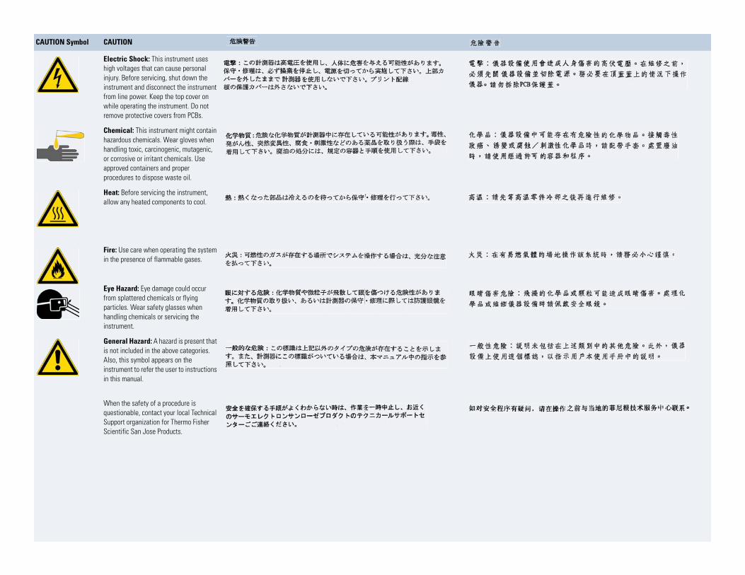
Electric Shock: This instrument uses high voltages that can cause personal injury. Before servicing, shut down the instrument and disconnect the instrument from line power. Keep the top cover on while operating the instrument. Do not remove protective covers from PCBs.
Elektroschock: In diesem Gerät werden Hochspannungen verwendet, die Verletzungen verursachen können. Vor Wartungsarbeiten muß das Gerät abgeschaltet und vom Netz getrennt werden. Betreiben Sie Wartungsarbeiten nicht mit abgenommenem Deckel. Nehmen Sie die Schutzabdeckung von Leiterplatten nicht ab.
Choc électrique: L’instrument utilise des tensions capables d’infliger des blessures corporelles. L’instrument doit être arrêté et débranché de la source de courant avant tout intervention. Ne pas utiliser l’instrument sans son couvercle. Ne pas enlever les étuis protecteurs des cartes de circuits imprimés.
Descarga eléctrica: Este insutiliza altas tensiones, capaceproducir lesiones personales. Adar servicio de mantenimientoinstrumento, éste debera apagdesconectarse de la línea de aeléctrica. No opere el instrumecubiertas exteriores quitadas. Nlas cubiertas protectoras de lade circuito impreso.
Chemical: This instrument might contain hazardous chemicals. Wear gloves when handling toxic, carcinogenic, mutagenic, or corrosive or irritant chemicals. Use approved containers and proper procedures to dispose waste oil.
Chemikalien: Dieses Gerät kann gefährliche Chemikalien enthalten. Tragen Sie Schutzhandschuhe beim Umgang mit toxischen, karzinogenen, mutagenen oder ätzenden/reizenden Chemikalien. Entsorgen Sie verbrauchtes Öl entsprechend den Vorschriften in den vorgeschriebenen Behältern.
Chimique: Des produits chimiques dangereux peuvent se trouver dans l’instrument. Portez des gants pour manipuler tous produits chimiques toxiques, cancérigènes, mutagènes, ou corrosifs/irritants. Utiliser des récipients et des procédures homologuées pour se débarrasser des déchets d’huile.
Química: El instrumento puedproductos quimicos peligrososguantes al manejar productos tóxicos, carcinogenos, mutagecorrosivos/irritantes. Utilice reprocedimientos aprobados pardeshacerse del aceite usado.
Heat: Before servicing the instrument, allow any heated components to cool.
Hitze: Warten Sie erhitzte Komponenten erst nachdem diese sich abgekühlt haben.
Haute Temperature: Permettre aux composants chauffés de refroidir avant tout intervention.
Altas temperaturas: Permitacomponentes se enfríen, ante servicio de mantenimiento.
Fire: Use care when operating the system in the presence of flammable gases.
Feuer: Beachten Sie die einschlägigen VorsichtsmaBnahmen, wenn Sie das System in Gegenwart von entzündbaren Gasen betreiben.
Incendie: Agir avec précaution lors de l’utilisation du système en présence de gaz inflammables.
Fuego: Tenga cuidado al opersistema en presencia de gasesinflamables.
Eye Hazard: Eye damage could occur from splattered chemicals or flying particles. Wear safety glasses when handling chemicals or servicing the instrument.
Verletzungsgefahr der Augen: Verspritzte Chemikalien oder kleine Partikel können Augenverletzungen verursachen. Tragen Sie beim Umgang mit Chemikalien oder bei der Wartung des Gerätes eine Schutzbrille.
Danger pour les yeux: Des projections chimiques, liquides, ou solides peuvent être dangereuses pour les yeux. Porter des lunettes de protection lors de toute manipulation de produit chimique ou pour toute intervention sur l’instrument.
Peligro par los ojos: Las salproductos químicos o particulasalten bruscamente pueden calesiones en los ojos. Utilice anprotectores al mnipular producquímicos o al darle servicio demantenimiento al instrumento
General Hazard: A hazard is present that is not included in the above categories. Also, this symbol appears on the instrument to refer the user to instructions in this manual.
Allgemeine Gefahr: Es besteht eine weitere Gefahr, die nicht in den vorstehenden Kategorien beschrieben ist. Dieses Symbol wird im Handbuch auBerdem dazu verwendet, um den Benutzer auf Anweisungen hinzuweisen.
Danger général: Indique la présence d’un risque n’appartenant pas aux catégories citées plus haut. Ce symbole figure également sur l’instrument pour renvoyer l’utilisateur aux instructions du présent manuel.
Peligro general: Significa qupeligro no incluido en las cateanteriores. Este simbolo tambien el instrumento par referir alas instrucciones contenidas emanual.
When the safety of a procedure is questionable, contact your local Technical Support organization for Thermo Fisher Scientific San Jose Products.
Wenn Sie sich über die Sicherheit eines Verfahrens im unklaren sind, setzen Sie sich, bevor Sie fortfahren, mit Ihrer lokalen technischen Unterstützungsorganisation für Thermo Fisher Scientific San Jose Produkte in Verbindung.
Si la sûreté d’une procédure est incertaine, avant de continuer, contacter le plus proche Service Clientèle pour les produits de Thermo Fisher Scientific San Jose.
Cuando la certidumbre acerca procedimiento sea dudosa, anproseguir, pongase en contactOficina de Asistencia Tecnica los productos de Thermo FisheSan Jose.
CAUTION Symbol CAUTION
Electric Shock: This instrument uses high voltages that can cause personal injury. Before servicing, shut down the instrument and disconnect the instrument from line power. Keep the top cover on while operating the instrument. Do not remove protective covers from PCBs.
Chemical: This instrument might contain hazardous chemicals. Wear gloves when handling toxic, carcinogenic, mutagenic, or corrosive or irritant chemicals. Use approved containers and proper procedures to dispose waste oil.
Heat: Before servicing the instrument, allow any heated components to cool.
Fire: Use care when operating the system in the presence of flammable gases.
Eye Hazard: Eye damage could occur from splattered chemicals or flying particles. Wear safety glasses when handling chemicals or servicing the instrument.
General Hazard: A hazard is present that is not included in the above categories. Also, this symbol appears on the instrument to refer the user to instructions in this manual.
When the safety of a procedure is questionable, contact your local Technical Support organization for Thermo Fisher Scientific San Jose Products.
C
Contents
Preface . . . . . . . . . . . . . . . . . . . . . . . . . . . . . . . . . . . . . . . . . . . . . . . . . . . . . . . . . . . . . . xiRelated Documentation . . . . . . . . . . . . . . . . . . . . . . . . . . . . . . . . . . . . . . . . . . .xiSafety and Special Notices . . . . . . . . . . . . . . . . . . . . . . . . . . . . . . . . . . . . . . . . xiiContacting Us . . . . . . . . . . . . . . . . . . . . . . . . . . . . . . . . . . . . . . . . . . . . . . . . .xiii
Chapter 1 Introduction . . . . . . . . . . . . . . . . . . . . . . . . . . . . . . . . . . . . . . . . . . . . . . . . . . . . . . . . . . .1Functional Description . . . . . . . . . . . . . . . . . . . . . . . . . . . . . . . . . . . . . . . . . . . . 2LightPipe Flow Cell. . . . . . . . . . . . . . . . . . . . . . . . . . . . . . . . . . . . . . . . . . . . . . . 3Lamps . . . . . . . . . . . . . . . . . . . . . . . . . . . . . . . . . . . . . . . . . . . . . . . . . . . . . . . . . 5Front and Back Panels . . . . . . . . . . . . . . . . . . . . . . . . . . . . . . . . . . . . . . . . . . . . . 6Status LEDs . . . . . . . . . . . . . . . . . . . . . . . . . . . . . . . . . . . . . . . . . . . . . . . . . . . . 7Specifications. . . . . . . . . . . . . . . . . . . . . . . . . . . . . . . . . . . . . . . . . . . . . . . . . . . . 8
Chapter 2 Installation . . . . . . . . . . . . . . . . . . . . . . . . . . . . . . . . . . . . . . . . . . . . . . . . . . . . . . . . . . . .9Installation Checklist. . . . . . . . . . . . . . . . . . . . . . . . . . . . . . . . . . . . . . . . . . . . . 10Unpacking and Inspecting the Instrument . . . . . . . . . . . . . . . . . . . . . . . . . . . . 11Placement and Environmental Requirements . . . . . . . . . . . . . . . . . . . . . . . . . . 12Installation Tools. . . . . . . . . . . . . . . . . . . . . . . . . . . . . . . . . . . . . . . . . . . . . . . . 12Checking the Power Setting and Fuses . . . . . . . . . . . . . . . . . . . . . . . . . . . . . . . 13Making the Back Panel Connections . . . . . . . . . . . . . . . . . . . . . . . . . . . . . . . . . 14
Connecting the UV/Vis Detector to the Data System Computer . . . . . . . . . 14Setting the Unit ID . . . . . . . . . . . . . . . . . . . . . . . . . . . . . . . . . . . . . . . . . . . . 15Making the Contact Closure Connections. . . . . . . . . . . . . . . . . . . . . . . . . . . 16Connecting the Analog Outputs . . . . . . . . . . . . . . . . . . . . . . . . . . . . . . . . . . 20Setting the Analog Output Voltage . . . . . . . . . . . . . . . . . . . . . . . . . . . . . . . . 21Making Remote Communications Connections . . . . . . . . . . . . . . . . . . . . . . 21
Installing the Flow Cell . . . . . . . . . . . . . . . . . . . . . . . . . . . . . . . . . . . . . . . . . . . 23Powering On the Detector for the First Time . . . . . . . . . . . . . . . . . . . . . . . . . . 24
Chapter 3 Maintenance . . . . . . . . . . . . . . . . . . . . . . . . . . . . . . . . . . . . . . . . . . . . . . . . . . . . . . . . .25Recommended Routine Maintenance . . . . . . . . . . . . . . . . . . . . . . . . . . . . . . . . 26Preventive Maintenance . . . . . . . . . . . . . . . . . . . . . . . . . . . . . . . . . . . . . . . . . . 26Maintenance Tools . . . . . . . . . . . . . . . . . . . . . . . . . . . . . . . . . . . . . . . . . . . . . . 27Cleaning Detector External Surfaces . . . . . . . . . . . . . . . . . . . . . . . . . . . . . . . . . 27
Thermo Scientific Surveyor UV/Vis Plus Detector Hardware Manual ix
Contents
LightPipe Flow Cell. . . . . . . . . . . . . . . . . . . . . . . . . . . . . . . . . . . . . . . . . . . . . . 27Removing the LightPipe Flow Cell . . . . . . . . . . . . . . . . . . . . . . . . . . . . . . . . 27Storing the LightPipe Flow Cell . . . . . . . . . . . . . . . . . . . . . . . . . . . . . . . . . . 30Installing the LightPipe Mounting Assembly . . . . . . . . . . . . . . . . . . . . . . . . . 30Installing the LightPipe Flow Cell . . . . . . . . . . . . . . . . . . . . . . . . . . . . . . . . 31
Standard Analytical Flow Cell . . . . . . . . . . . . . . . . . . . . . . . . . . . . . . . . . . . . . . 33Removing the Standard Analytical Flow Cell Assembly . . . . . . . . . . . . . . . . . 33Installing the Standard Analytical Flow Cell . . . . . . . . . . . . . . . . . . . . . . . . . 35
Cleaning the Flow Cells. . . . . . . . . . . . . . . . . . . . . . . . . . . . . . . . . . . . . . . . . . . 36Cleaning the Flow Cell with Organic Solvents. . . . . . . . . . . . . . . . . . . . . . . . 36Cleaning the Flow Cell with Nitric Acid . . . . . . . . . . . . . . . . . . . . . . . . . . . . 37
Lamp Maintenance . . . . . . . . . . . . . . . . . . . . . . . . . . . . . . . . . . . . . . . . . . . . . . 38Checking the Deuterium Lamp Usage Hours and Replacing the Lamp. . . . . 38Replacing the Tungsten Lamp. . . . . . . . . . . . . . . . . . . . . . . . . . . . . . . . . . . . 43
Chapter 4 Troubleshooting. . . . . . . . . . . . . . . . . . . . . . . . . . . . . . . . . . . . . . . . . . . . . . . . . . . . . . .47Detector-Related Problems . . . . . . . . . . . . . . . . . . . . . . . . . . . . . . . . . . . . . . . . 48Error Messages . . . . . . . . . . . . . . . . . . . . . . . . . . . . . . . . . . . . . . . . . . . . . . . . . 51
Chapter 5 Accessories and Replaceable Parts . . . . . . . . . . . . . . . . . . . . . . . . . . . . . . . . . . . . .53Replaceable Parts . . . . . . . . . . . . . . . . . . . . . . . . . . . . . . . . . . . . . . . . . . . . . . . . 53Optional Flow Cells for the UV/Vis Detector . . . . . . . . . . . . . . . . . . . . . . . . . . 54
Appendix A Surveyor Firmware Upgrade Utility . . . . . . . . . . . . . . . . . . . . . . . . . . . . . . . . . . . . . .55
Index . . . . . . . . . . . . . . . . . . . . . . . . . . . . . . . . . . . . . . . . . . . . . . . . . . . . . . . . . . . . . . . .59
x Surveyor UV/Vis Plus Detector Hardware Manual Thermo Scientific
P
Preface
This manual describes how to set up and maintain the Surveyor™ UV/Vis Plus Detector.
Related DocumentationIn addition to the instrument control Help provided with your data system, Thermo Fisher Scientific provides these documents as PDF files for the Surveyor UV/Vis Plus Detector:
• Surveyor Plus Preinstallation Requirements Guide
• Surveyor Plus Getting Connected Guide
• Surveyor UV/Vis Plus Detector Hardware Manual
• A Surveyor Plus user guide for each data system
Thermo Scientific Surveyor UV/Vis Plus Detector Hardware Manual xi

Preface
Safety and Special NoticesMake sure you follow the precautionary statements presented in this guide. The safety and other special notices appear in boxes.
Safety and special notices include the following:
CAUTION Highlights hazards to humans, property, or the environment. Each CAUTION notice is accompanied by an appropriate CAUTION symbol.
CAUTION Alerts you to the presence of hot surfaces and to the potential injury that could occur were you to come in contact with a specific instrument area.
CAUTION Alerts you to the presence of an eye hazard and the requirement for wearing protective safety glasses.
CAUTION Alerts you to the presence of a UV light hazard. UV
IMPORTANT Highlights information necessary to prevent damage to software, loss of data, or invalid test results; or might contain information that is critical for optimal performance of the system.
Note Highlights information of general interest.
Tip Highlights helpful information that can make a task easier.
xii Surveyor UV/Vis Plus Detector Hardware Manual Thermo Scientific
Preface
Contacting UsThere are several ways to contact Thermo Fisher Scientific for the information you need.
To contact Technical Support
Find software updates and utilities to download at mssupport.thermo.com.
To contact Customer Service for ordering information
To get local contact information for sales or service
Go to www.thermoscientific.com/wps/portal/ts/contactus.
To copy manuals from the Internet
Go to mssupport.thermo.com, agree to the Terms and Conditions, and then click Customer Manuals in the left margin of the window.
To suggest changes to documentation or to Help
• Fill out a reader survey online at www.surveymonkey.com/s/PQM6P62.
• Send an e-mail message to the Technical Publications Editor at [email protected].
Phone 800-532-4752
Fax 561-688-8736
E-mail [email protected]
Knowledge base www.thermokb.com
Phone 800-532-4752
Fax 561-688-8731
E-mail [email protected]
Web site www.thermo.com/ms
Thermo Scientific Surveyor UV/Vis Plus Detector Hardware Manual xiii


1
Introduction
The Surveyor UV/Vis Plus Detector (see Figure 1) is a member of the Surveyor Plus™ family of LC instruments.
This chapter provides an introduction to the Surveyor UV/Vis Plus Detector.
Figure 1. Surveyor UV/Vis Plus Detector
Contents
• Functional Description
• LightPipe Flow Cell
• Lamps
• Front and Back Panels
• Status LEDs
• Specifications
Thermo Scientific Surveyor UV/Vis Plus Detector Hardware Manual 1

1 IntroductionFunctional Description
Functional DescriptionThe Surveyor UV/Vis Plus Detector is a full-featured, time-programmable, variable-wavelength UV/Vis (ultraviolet/visible) absorbance detector. It operates in either the single or dual wavelength mode in the UV or visible ranges.
The UV/Vis detector is a benchtop unit for inclusion into the Surveyor Plus LC System. You control the detector remotely over an Ethernet communications link from a Thermo Scientific data system computer.
The UV/Vis detector consists of a dual light source, an optical bench (see Figure 2), dual photodiode detectors, and several printed circuit boards (PCBs).
Figure 2. Surveyor UV/Vis Plus Detector optical bench
To provide a complete spectrum of ultraviolet (UV) and visible light, the detector uses a deuterium lamp (D2) for the UV range (190 to 365 nm) and a tungsten lamp (W) for the visible range (366 to 800 nm). The lamp cover has a safety interlock that reduces the possibility of human exposure to harmful UV light. When you remove the cover, the lamps automatically turn off. A computer-controlled shutter selects the deuterium lamp for sample analyses in the UV range and the tungsten lamp for sample analyses in the visible range. The light from the selected lamp goes to a holographic grating that disperses the light into a spectrum. The grating turns to select the programmed wavelength. For precise wavelength control, a stepper motor controls the alignment of the grating. A system of baffles that reduces stray light in the optical bench increases the absorbance linearity.
Tungstenlamp
Deuteriumlamp
Samplephotodiode
Referencephotodiode
Lens
Flow cell
Beamsplitter
ShutterGrating
2 Surveyor UV/Vis Plus Detector Hardware Manual Thermo Scientific
1 IntroductionLightPipe Flow Cell
From the grating, the light travels to a fiber optic beamsplitter, where a portion of the light is redirected to a reference photodiode. The signal from the reference photodiode compensates for changes in lamp intensity and helps maintain consistent performance as the lamp performance varies. From the beamsplitter, most of the light passes through a lens and then on through the flow cell and onto the sample photodiode. The analog PC board converts the intensity counts from the photons falling on the sample photodiode into data that the data system can process.
Light-emitting diodes (LEDs) on the front of the module provide information about power, communications, run, and lamp status. See “Status LEDs” on page 7.
You can order the UV/Vis detector with one of these flow cell options:
• Standard analytical flow cell with a 10 mm path length
• LightPipe™ flow cell with a 50 mm path length
You can order other flow cells as options for the detector. See Table 5.
LightPipe Flow CellThe internal bore of the LightPipe flow cell is 50 mm long and has a volume of 10 μL. The 5 cm optical path length produces a signal five times that of a conventional 1 cm flow cell, while the low internal volume of 10 μL minimizes band broadening. A special low refractive index coating of the internal bore ensures a high optical throughput and minimizes short-term noise.
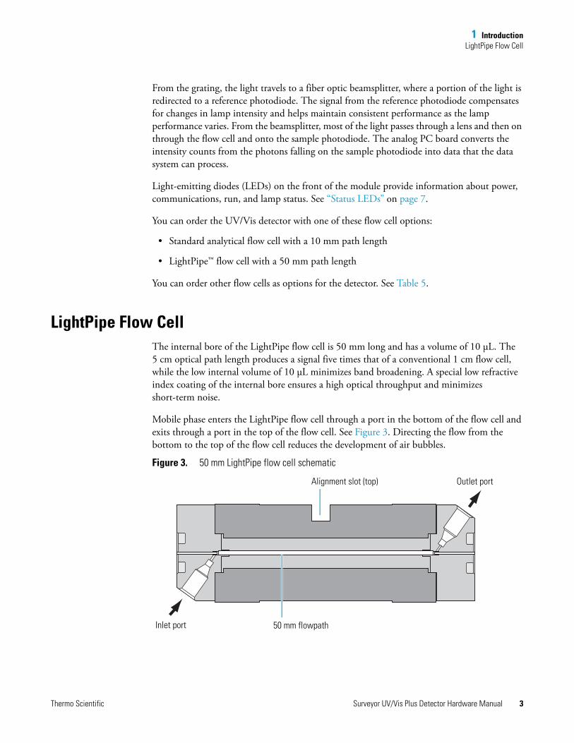
Mobile phase enters the LightPipe flow cell through a port in the bottom of the flow cell and exits through a port in the top of the flow cell. See Figure 3. Directing the flow from the bottom to the top of the flow cell reduces the development of air bubbles.
Figure 3. 50 mm LightPipe flow cell schematic
50 mm flowpathInlet port
Alignment slot (top) Outlet port
Thermo Scientific Surveyor UV/Vis Plus Detector Hardware Manual 3
1 IntroductionLightPipe Flow Cell
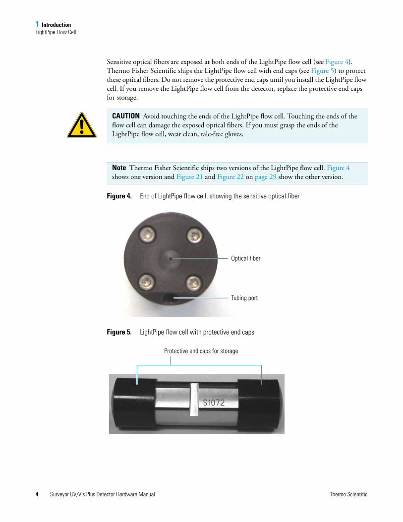
Sensitive optical fibers are exposed at both ends of the LightPipe flow cell (see Figure 4). Thermo Fisher Scientific ships the LightPipe flow cell with end caps (see Figure 5) to protect these optical fibers. Do not remove the protective end caps until you install the LightPipe flow cell. If you remove the LightPipe flow cell from the detector, replace the protective end caps for storage.
Figure 4. End of LightPipe flow cell, showing the sensitive optical fiber
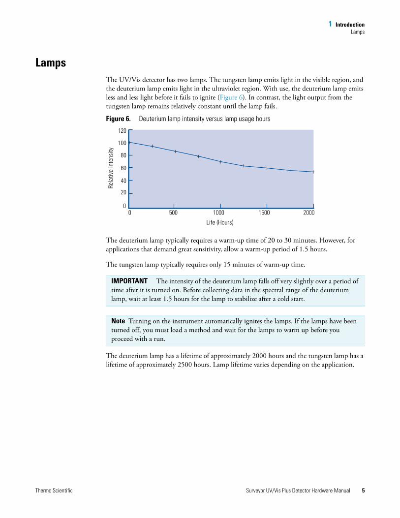
Figure 5. LightPipe flow cell with protective end caps
CAUTION Avoid touching the ends of the LightPipe flow cell. Touching the ends of the flow cell can damage the exposed optical fibers. If you must grasp the ends of the LightPipe flow cell, wear clean, talc-free gloves.
Note Thermo Fisher Scientific ships two versions of the LightPipe flow cell. Figure 4 shows one version and Figure 21 and Figure 22 on page 29 show the other version.
Optical fiber
Tubing port
Protective end caps for storage
4 Surveyor UV/Vis Plus Detector Hardware Manual Thermo Scientific
1 IntroductionLamps
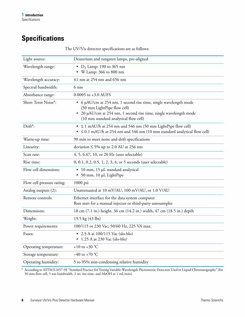
LampsThe UV/Vis detector has two lamps. The tungsten lamp emits light in the visible region, and the deuterium lamp emits light in the ultraviolet region. With use, the deuterium lamp emits less and less light before it fails to ignite (Figure 6). In contrast, the light output from the tungsten lamp remains relatively constant until the lamp fails.
Figure 6. Deuterium lamp intensity versus lamp usage hours
The deuterium lamp typically requires a warm-up time of 20 to 30 minutes. However, for applications that demand great sensitivity, allow a warm-up period of 1.5 hours.
The tungsten lamp typically requires only 15 minutes of warm-up time.
The deuterium lamp has a lifetime of approximately 2000 hours and the tungsten lamp has a lifetime of approximately 2500 hours. Lamp lifetime varies depending on the application.
IMPORTANT The intensity of the deuterium lamp falls off very slightly over a period of time after it is turned on. Before collecting data in the spectral range of the deuterium lamp, wait at least 1.5 hours for the lamp to stabilize after a cold start.
Note Turning on the instrument automatically ignites the lamps. If the lamps have been turned off, you must load a method and wait for the lamps to warm up before you proceed with a run.
+ + + + +
+ +
+ +
0 500 1000 1500 2000 0
20
40
60
80
100
120
Life (Hours)
Rela
tive
Inte
nsity
Thermo Scientific Surveyor UV/Vis Plus Detector Hardware Manual 5
1 IntroductionFront and Back Panels
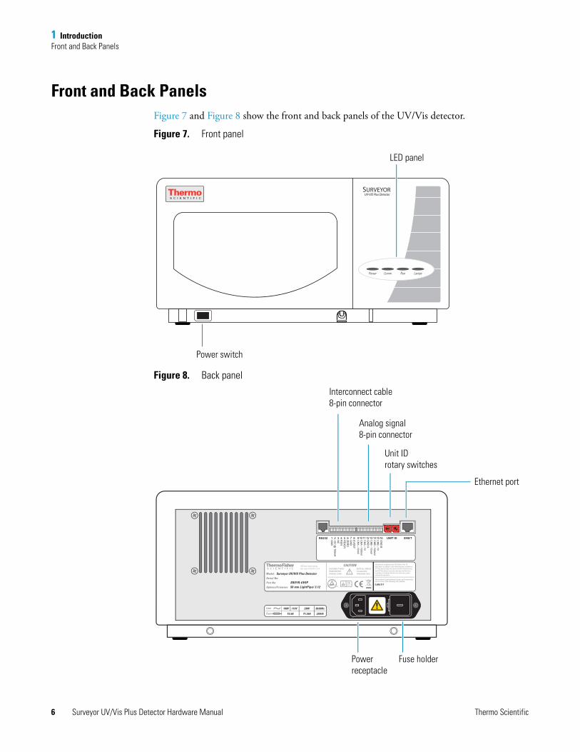
Front and Back PanelsFigure 7 and Figure 8 show the front and back panels of the UV/Vis detector.
Figure 7. Front panel
Figure 8. Back panel
Power Comm Run Lamps
UV-VIS Plus DetectorSURVEYOR
Power switch
LED panel
Surveyor UV/VIS Plus Detector
SRVYR-UV5P5,608,517
50 mm LightPipe/ 3.1261010 - 1
Model:
Serial No:
Part No:
Options/Firmware
This product is manufactured under, and covered by,one or more of the following U.S. patents:
355 River Oaks ParkwaySan Jose, CA 95134 U.S.A.
This device complies with FCC Rules, Part 15. Operation is subject to the following two conditions: (1) This device may not cause harmful interference, and (2) This device must accept any interference received, including interference that may cause undesired operation.
DISCONNECT INPUT POWER BEFORE OPENING COVER.
REFER ALL SERVICETO QUALIFIEDPERSONNEL ONLY.
CAUTION
T2.5A T1.25A 225VA
100V 115V 230V 50/60HzLine
Fuse
ENETUNIT IDGN
D B
CH
B - 1V
CH
B - 100m
VC
HB
- 10mV
GN
D A
CH
A - 1V
CH
A - 100m
VC
HA
- 10mV
EV
EN
TG
ND
ZER
OR
EA
DY
RU
NN
C+5V
@ 150m
AG
ND
9 10 11 12 13 14 15 161 2 3 4 5 6 7 8RS232
1
2 3
45
6
78
90
1
2 3
45
6
78
90
Analog signal8-pin connector
Interconnect cable8-pin connector
Ethernet port
Fuse holderPower receptacle
Unit IDrotary switches
6 Surveyor UV/Vis Plus Detector Hardware Manual Thermo Scientific

1 IntroductionStatus LEDs
Status LEDsTable 1 describes the four LEDs on the front panel of the detector (see Figure 9).
Figure 9. Status LEDs for the UV/Vis detector
Table 1. Status LEDs and their meanings
LED State Meaning
Power Green The detector is on.
Comm Green Communication to the data system computer has been established.
Amber There is no communication with the data system.
Run Green The detector is ready for a run.
Flashing green A run is in progress and the detector is sending data to the data system computer.
Flashing Amber An error has occurred during a run.
Lamps Green One or both lamps are turned on.
Amber The lamps are off.
Power Comm Run Lamps
Thermo Scientific Surveyor UV/Vis Plus Detector Hardware Manual 7
1 IntroductionSpecifications
SpecificationsThe UV/Vis detector specifications are as follows:
Light source: Deuterium and tungsten lamps, pre-aligned
Wavelength range: • D2 Lamp: 190 to 365 nm• W Lamp: 366 to 800 nm
Wavelength accuracy: ±1 nm at 254 nm and 656 nm
Spectral bandwidth: 6 nm
Absorbance range: 0.0005 to +3.0 AUFS
Short Term Noisea: • 6 μAU/cm at 254 nm, 1 second rise time, single wavelength mode (50 mm LightPipe flow cell)
• 20 μAU/cm at 254 nm, 1 second rise time, single wavelength mode (10 mm standard analytical flow cell)
Drifta: • ≤ 1 mAU/h at 254 nm and 546 nm (50 mm LightPipe flow cell)• ≤ 0.1 mAU/h at 254 nm and 546 nm (10 mm standard analytical flow cell)
Warm-up time: 90 min to meet noise and drift specifications
Linearity: deviation ≤ 5% up to 2.0 AU at 256 nm
Scan rate: 4, 5, 6.67, 10, or 20 Hz (user selectable)
Rise time: 0, 0.1, 0.2, 0.5, 1, 2, 3, 4, or 5 seconds (user selectable)
Flow cell dimensions: • 10 mm, 15 μL standard analytical• 50 mm, 10 μL LightPipe
Flow cell pressure rating: 1000 psi
Analog outputs (2): Unattenuated at 10 mV/AU, 100 mV/AU, or 1.0 V/AU
Remote controls: Ethernet interface for the data system computerRun start for a manual injector or third-party autosampler
Dimensions: 18 cm (7.1 in.) height, 36 cm (14.2 in.) width, 47 cm (18.5 in.) depth
Weight: 19.5 kg (43 lbs)
Power requirements: 100/115 or 230 Vac; 50/60 Hz, 225 VA max.
Fuses: • 2.5 A at 100/115 Vac (slo-blo)• 1.25 A at 230 Vac (slo-blo)
Operating temperature: +10 to +30 °C
Storage temperature: –40 to +70 °C
Operating humidity: 5 to 95% non-condensing relative humiditya According to ASTM E1657-94 “Standard Practice for Testing Variable-Wavelength Photometric Detectors Used in Liquid Chromatography” (for
50 mm flow cell, 5 nm bandwidth, 2 sec rise time, and MeOH at 1 mL/min).
8 Surveyor UV/Vis Plus Detector Hardware Manual Thermo Scientific
2
Installation
To install the Surveyor UV/Vis Plus Detector as part of a Surveyor LC system, use the “Installation Checklist” on page 10 and follow the procedures in this chapter.
Contents
• Installation Checklist
• Unpacking and Inspecting the Instrument
• Placement and Environmental Requirements
• Checking the Power Setting and Fuses
• Making the Back Panel Connections
• Installing the Flow Cell
• Powering On the Detector for the First Time
Thermo Scientific Surveyor UV/Vis Plus Detector Hardware Manual 9
2 InstallationInstallation Checklist
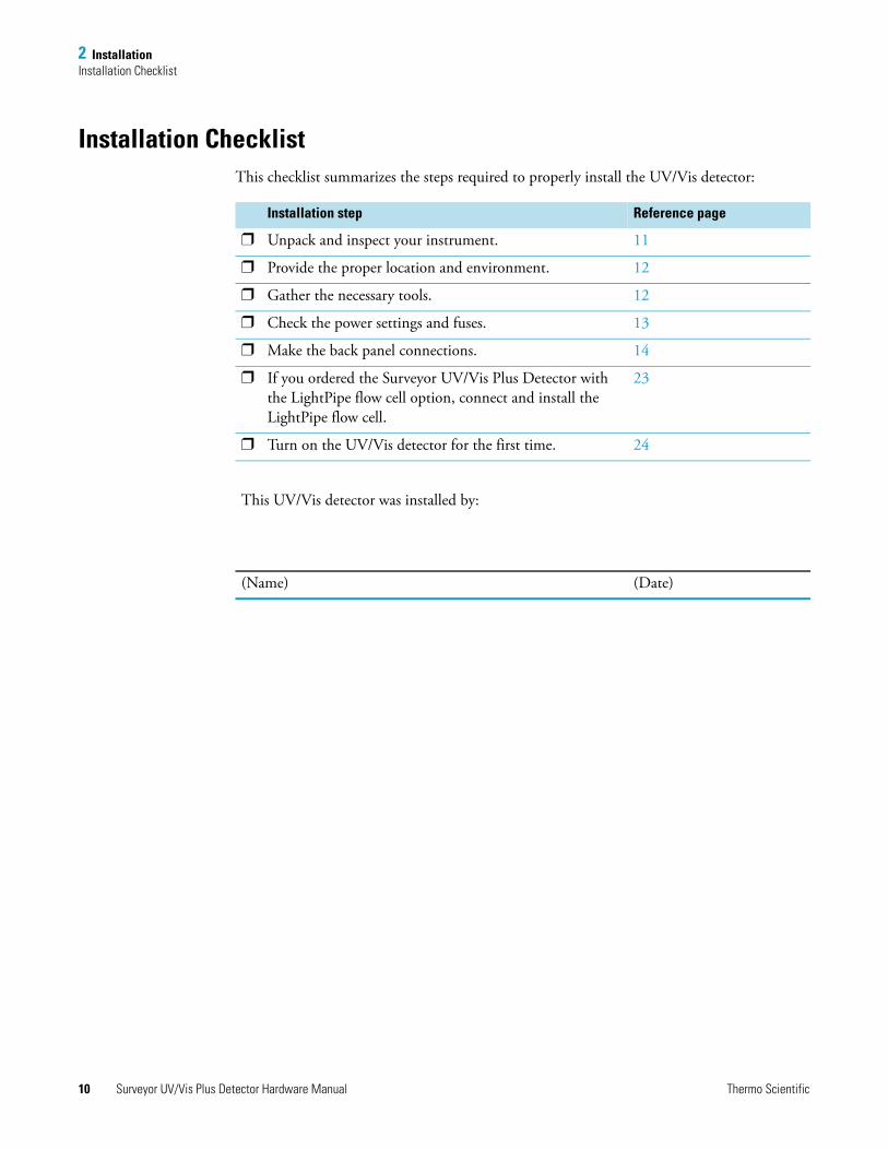
Installation ChecklistThis checklist summarizes the steps required to properly install the UV/Vis detector:
Installation step Reference page
Unpack and inspect your instrument. 11
Provide the proper location and environment. 12
Gather the necessary tools. 12
Check the power settings and fuses. 13
Make the back panel connections. 14
If you ordered the Surveyor UV/Vis Plus Detector with the LightPipe flow cell option, connect and install the LightPipe flow cell.
23
Turn on the UV/Vis detector for the first time. 24
This UV/Vis detector was installed by:
(Name) (Date)
10 Surveyor UV/Vis Plus Detector Hardware Manual Thermo Scientific
2 InstallationUnpacking and Inspecting the Instrument
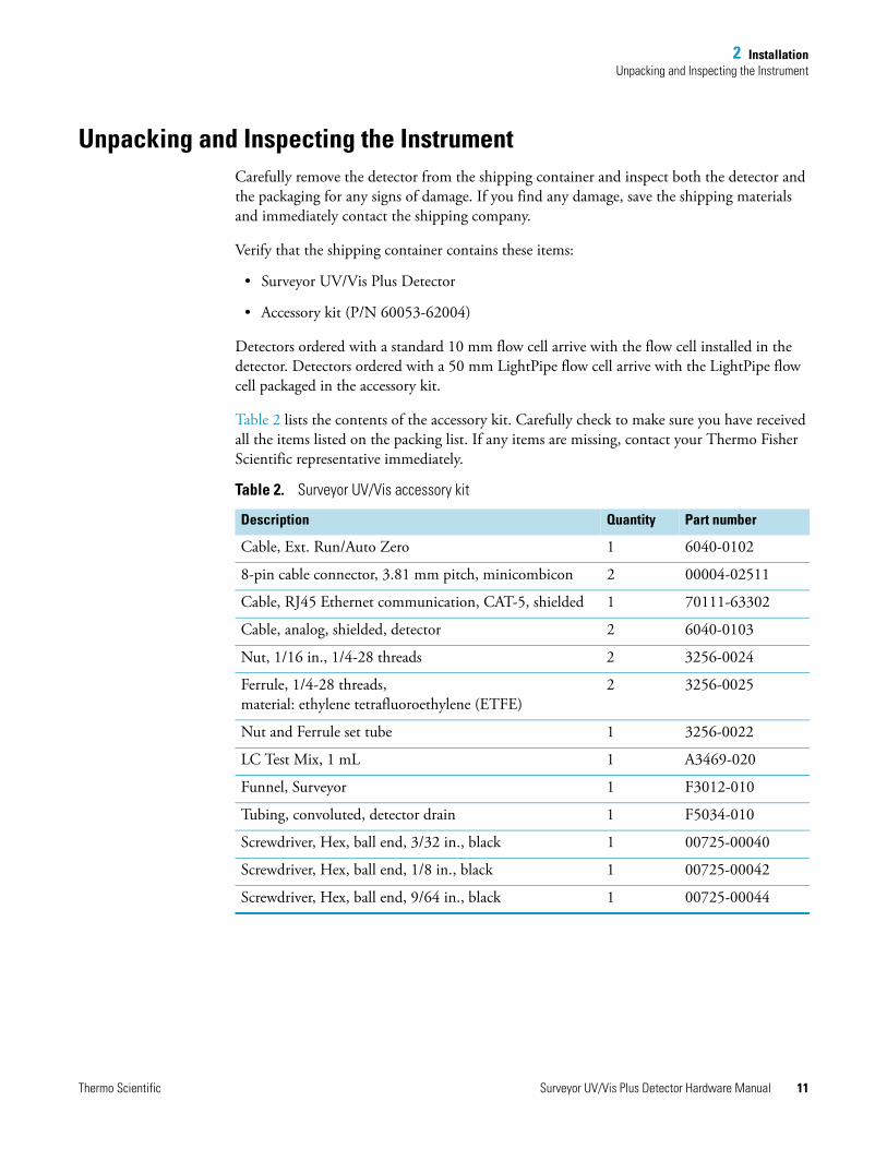
Unpacking and Inspecting the InstrumentCarefully remove the detector from the shipping container and inspect both the detector and the packaging for any signs of damage. If you find any damage, save the shipping materials and immediately contact the shipping company.
Verify that the shipping container contains these items:
• Surveyor UV/Vis Plus Detector
• Accessory kit (P/N 60053-62004)
Detectors ordered with a standard 10 mm flow cell arrive with the flow cell installed in the detector. Detectors ordered with a 50 mm LightPipe flow cell arrive with the LightPipe flow cell packaged in the accessory kit.
Table 2 lists the contents of the accessory kit. Carefully check to make sure you have received all the items listed on the packing list. If any items are missing, contact your Thermo Fisher Scientific representative immediately.
Table 2. Surveyor UV/Vis accessory kit
Description Quantity Part number
Cable, Ext. Run/Auto Zero 1 6040-0102
8-pin cable connector, 3.81 mm pitch, minicombicon 2 00004-02511
Cable, RJ45 Ethernet communication, CAT-5, shielded 1 70111-63302
Cable, analog, shielded, detector 2 6040-0103
Nut, 1/16 in., 1/4-28 threads 2 3256-0024
Ferrule, 1/4-28 threads, material: ethylene tetrafluoroethylene (ETFE)
2 3256-0025
Nut and Ferrule set tube 1 3256-0022
LC Test Mix, 1 mL 1 A3469-020
Funnel, Surveyor 1 F3012-010
Tubing, convoluted, detector drain 1 F5034-010
Screwdriver, Hex, ball end, 3/32 in., black 1 00725-00040
Screwdriver, Hex, ball end, 1/8 in., black 1 00725-00042
Screwdriver, Hex, ball end, 9/64 in., black 1 00725-00044
Thermo Scientific Surveyor UV/Vis Plus Detector Hardware Manual 11
2 InstallationPlacement and Environmental Requirements
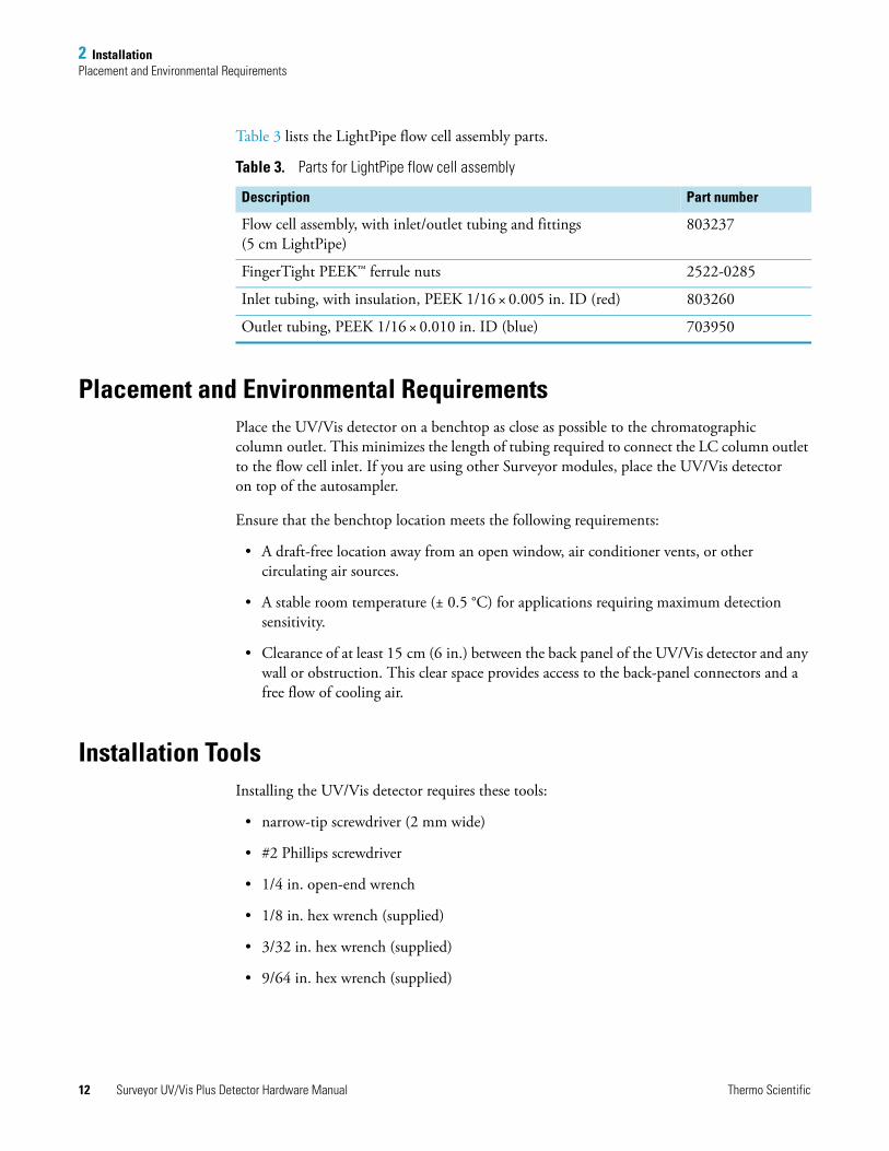
Table 3 lists the LightPipe flow cell assembly parts.
Placement and Environmental RequirementsPlace the UV/Vis detector on a benchtop as close as possible to the chromatographic column outlet. This minimizes the length of tubing required to connect the LC column outlet to the flow cell inlet. If you are using other Surveyor modules, place the UV/Vis detector on top of the autosampler.
Ensure that the benchtop location meets the following requirements:
• A draft-free location away from an open window, air conditioner vents, or other circulating air sources.
• A stable room temperature (± 0.5 °C) for applications requiring maximum detection sensitivity.
• Clearance of at least 15 cm (6 in.) between the back panel of the UV/Vis detector and any wall or obstruction. This clear space provides access to the back-panel connectors and a free flow of cooling air.
Installation ToolsInstalling the UV/Vis detector requires these tools:
• narrow-tip screwdriver (2 mm wide)
• #2 Phillips screwdriver
• 1/4 in. open-end wrench
• 1/8 in. hex wrench (supplied)
• 3/32 in. hex wrench (supplied)
• 9/64 in. hex wrench (supplied)
Table 3. Parts for LightPipe flow cell assembly
Description Part number
Flow cell assembly, with inlet/outlet tubing and fittings (5 cm LightPipe)
803237
FingerTight PEEK™ ferrule nuts 2522-0285
Inlet tubing, with insulation, PEEK 1/16 × 0.005 in. ID (red) 803260
Outlet tubing, PEEK 1/16 × 0.010 in. ID (blue) 703950
12 Surveyor UV/Vis Plus Detector Hardware Manual Thermo Scientific
2 InstallationChecking the Power Setting and Fuses
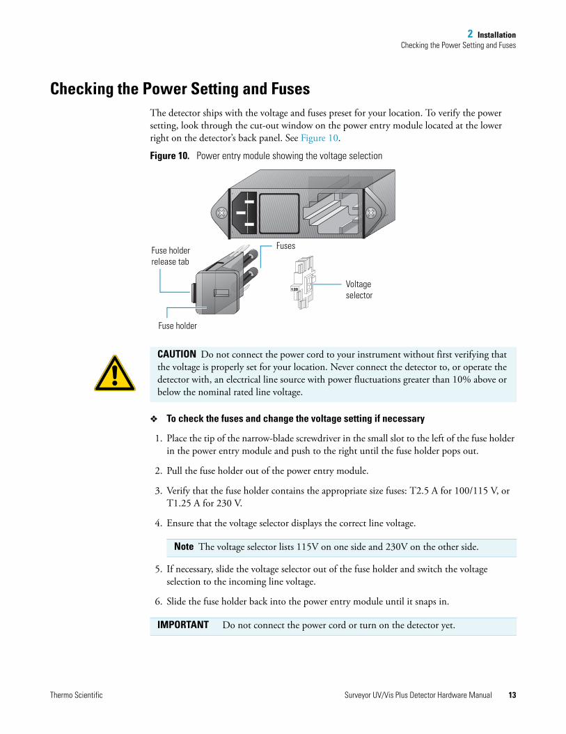
Checking the Power Setting and FusesThe detector ships with the voltage and fuses preset for your location. To verify the power setting, look through the cut-out window on the power entry module located at the lower right on the detector’s back panel. See Figure 10.
Figure 10. Power entry module showing the voltage selection
To check the fuses and change the voltage setting if necessary
1. Place the tip of the narrow-blade screwdriver in the small slot to the left of the fuse holder in the power entry module and push to the right until the fuse holder pops out.
2. Pull the fuse holder out of the power entry module.
3. Verify that the fuse holder contains the appropriate size fuses: T2.5 A for 100/115 V, or T1.25 A for 230 V.
4. Ensure that the voltage selector displays the correct line voltage.
5. If necessary, slide the voltage selector out of the fuse holder and switch the voltage selection to the incoming line voltage.
6. Slide the fuse holder back into the power entry module until it snaps in.
Voltage selector
FusesFuse holder release tab
Fuse holder
CAUTION Do not connect the power cord to your instrument without first verifying that the voltage is properly set for your location. Never connect the detector to, or operate the detector with, an electrical line source with power fluctuations greater than 10% above or below the nominal rated line voltage.
Note The voltage selector lists 115V on one side and 230V on the other side.
IMPORTANT Do not connect the power cord or turn on the detector yet.
Thermo Scientific Surveyor UV/Vis Plus Detector Hardware Manual 13
2 InstallationMaking the Back Panel Connections
Making the Back Panel ConnectionsUse the cables provided in the UV/Vis detector accessory kit to make the back panel connections.
For a stand-alone Surveyor LC system, you must connect the UV/Vis detector to the data system computer as described in “Connecting the UV/Vis Detector to the Data System Computer” on page 14. You must also connect the system interconnect cable that transmits the start signal from the autosampler to the detector during an injection cycle as described in “Making the Contact Closure Connections” on page 16.
If you are using an autosampler that is not controlled from your Thermo Scientific data system, use the remote communications pins on the detector’s back panel to trigger the detector as described in “Making Remote Communications Connections” on page 21.
To make the back panel connections, follow these procedures:
• Connecting the UV/Vis Detector to the Data System Computer
• Setting the Unit ID
• Making the Contact Closure Connections
• Connecting the Analog Outputs
• Setting the Analog Output Voltage
• Making Remote Communications Connections
Connecting the UV/Vis Detector to the Data System Computer
Connect your Ethernet switch to the Ethernet connector port of the detector using the supplied shielded Ethernet cable (P/N 70111-63302).
If your are connecting more than one Surveyor UV/Vis Plus Detector to the same data system computer, make sure that Unit IDs for the two detectors are set to different values (see “Setting the Unit ID” on page 15).
14 Surveyor UV/Vis Plus Detector Hardware Manual Thermo Scientific
2 InstallationMaking the Back Panel Connections
Setting the Unit ID
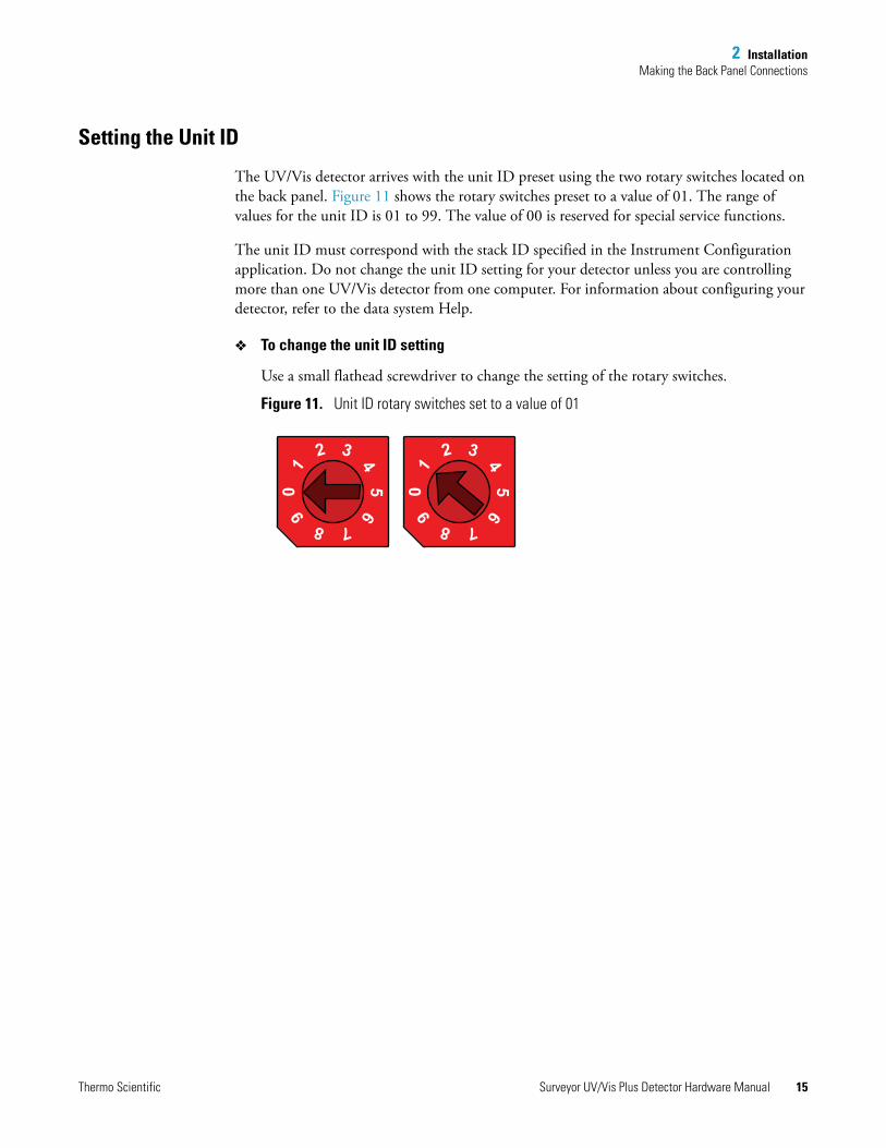
The UV/Vis detector arrives with the unit ID preset using the two rotary switches located on the back panel. Figure 11 shows the rotary switches preset to a value of 01. The range of values for the unit ID is 01 to 99. The value of 00 is reserved for special service functions.
The unit ID must correspond with the stack ID specified in the Instrument Configuration application. Do not change the unit ID setting for your detector unless you are controlling more than one UV/Vis detector from one computer. For information about configuring your detector, refer to the data system Help.
To change the unit ID setting
Use a small flathead screwdriver to change the setting of the rotary switches.
Figure 11. Unit ID rotary switches set to a value of 011
2 3
45
6
78
90
1
2 3
45
6
78
90
Thermo Scientific Surveyor UV/Vis Plus Detector Hardware Manual 15

2 InstallationMaking the Back Panel Connections
Making the Contact Closure Connections
The system interconnect cable coordinates the timing of the Surveyor plus modules during an injection sequence.
There are two versions of the system interconnect cable (contact closure):
• The older version has five combicon connectors. You can identify the detector connector by the DET tag on its adjacent cable as shown in Figure 12.
• The newer version has seven combicon connectors, with three connectors labeled DETECTOR as shown in Figure 13.
Figure 12. 5-connector version of the system interconnect cable
Figure 13. 7-connector version of the system interconnect cable
LC P
UM
P
MS
PU
MP
M/S
A/S
DET F5049-010
ToMS detector
ToSurveyor MS
Pump Plus
Toautosampler
Todetector
ToSurveyor LC Pump Plus
DE
TE
CTO
R
DE
TE
CTO
R
DE
TE
CTO
R
PU
MP
PU
MP
A/S
M/S
ToMS detector
Toautosampler
Todetector
Todetector
Todetector
Topump
Topump
16 Surveyor UV/Vis Plus Detector Hardware Manual Thermo Scientific
2 InstallationMaking the Back Panel Connections
Connecting the 5-Connector System Interconnect Cable
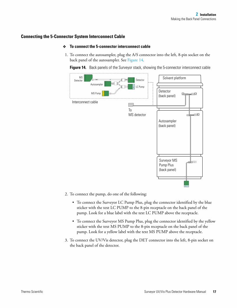
To connect the 5-connector interconnect cable
1. To connect the autosampler, plug the A/S connector into the left, 8-pin socket on the back panel of the autosampler. See Figure 14.
Figure 14. Back panels of the Surveyor stack, showing the 5-connector interconnect cable
2. To connect the pump, do one of the following:
• To connect the Surveyor LC Pump Plus, plug the connector identified by the blue sticker with the text LC PUMP to the 8-pin receptacle on the back panel of the pump. Look for a blue label with the text LC PUMP above the receptacle.
• To connect the Surveyor MS Pump Plus, plug the connector identified by the yellow sticker with the text MS PUMP to the 8-pin receptacle on the back panel of the pump. Look for a yellow label with the text MS PUMP above the receptacle.
3. To connect the UV/Vis detector, plug the DET connector into the left, 8-pin socket on the back panel of the detector.
LC PUMP
LC P
UM
P
MS
PU
MP
M/S
A/S
DET
MSDetector
Autosampler
MS Pump
Detector
LC Pump
Interconnect cable
Solvent platform
Detector(back panel)
Autosampler(back panel)
Surveyor MS Pump Plus(back panel)
ToMS detector
Thermo Scientific Surveyor UV/Vis Plus Detector Hardware Manual 17
2 InstallationMaking the Back Panel Connections
Connecting the 7-Connector System Interconnect Cable
To connect the 7-connector system interconnect cable to the LC modules
1. To connect the Surveyor Autosampler Plus, plug the A/S connector into the left, 8-pin socket on the back panel of the autosampler as shown in Figure 16.
2. To connect the pump, do the following:
• To connect the Surveyor LC Pump Plus, plug a connector labeled PUMP into the 8-pin socket on the back panel of the pump.
• To connect the Surveyor MS Pump Plus, do the following:
– Connect the end of the adapter cable labeled PUMP to one of the PUMP connectors of the 7-connector interconnect cable.
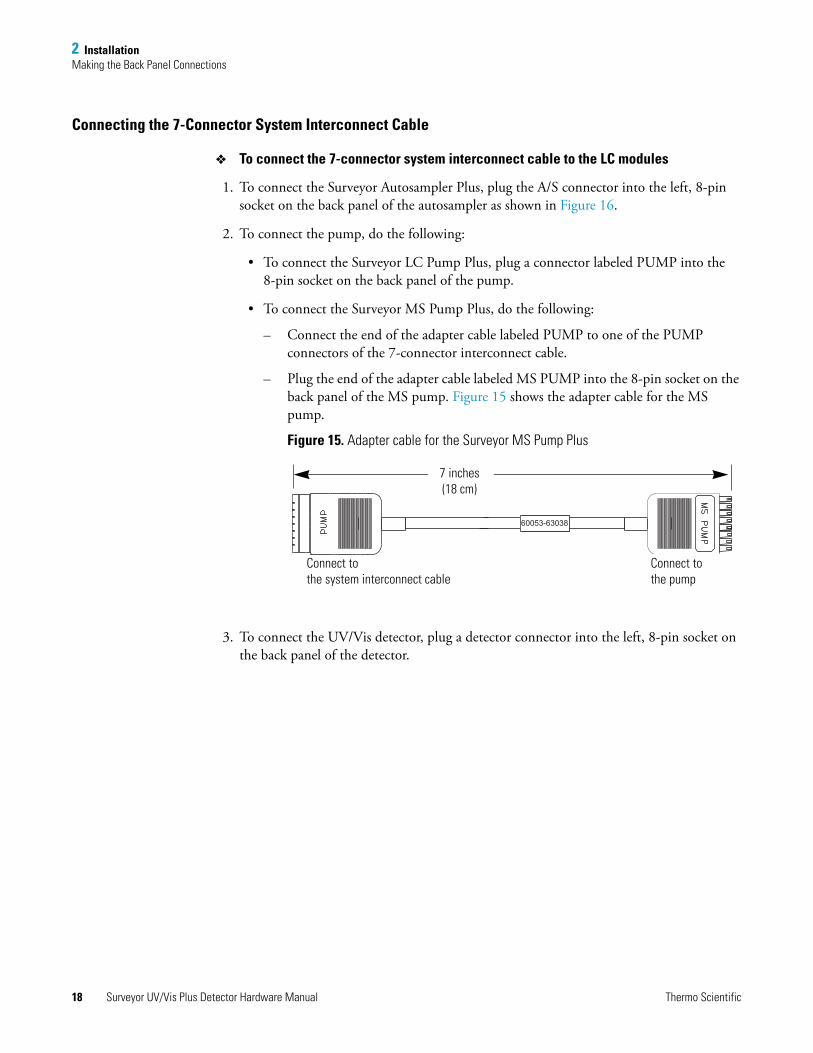
– Plug the end of the adapter cable labeled MS PUMP into the 8-pin socket on the back panel of the MS pump. Figure 15 shows the adapter cable for the MS pump.
Figure 15. Adapter cable for the Surveyor MS Pump Plus
3. To connect the UV/Vis detector, plug a detector connector into the left, 8-pin socket on the back panel of the detector.
60053-63038
7 inches(18 cm)
Connect to the system interconnect cable
Connect to the pump
18 Surveyor UV/Vis Plus Detector Hardware Manual Thermo Scientific

2 InstallationMaking the Back Panel Connections
Figure 16. Back panels of the modules of a Surveyor Plus LC system, showing the 7-connector system interconnect cable
PU
MP
MS
PU
MP
DE
TE
CTO
R
DE
TE
CTO
R
DE
TE
CTO
R
PU
MP
PU
MP
A/S
M/S
DE
TE
CTO
R
DE
TE
CTO
R
DE
TE
CTO
R
DE
TE
CTO
R
PUMP
PUMP
MS Detector
Autosampler
Pump
Detector
Detector
Interconnect cable
Solvent platform
Autosampler(back panel)
Surveyor LC Pump Plus(back panel)
Detector(back panel)
Pump
Detector
Solvent platform
Autosampler(back panel)
Surveyor MS Pump Plus (back panel)
Detector(back panel)
ToMS detector
ToMS detector
MS pump connection
Not drawn to scale
Pumpconnector
Pump connector of adapter cable
Surveyor MS Pump connector
MS pump adapter cable
Thermo Scientific Surveyor UV/Vis Plus Detector Hardware Manual 19
2 InstallationMaking the Back Panel Connections
Connecting the Analog Outputs
The installation kit provides two analog signal cables (twin-axial computer cables) to connect the analog outputs from the UV/Vis detector to other data collection devices.
The analog signal cables have three wires protruding from the ends of the shielded cable. Two of these wires are electrically insulated and carry an analog signal to data collection devices. Typically, the wire with the clear insulation is connected to the positive analog output, and the wire with the black insulation is connected to the signal ground (sometimes referred to as the negative signal). The third wire is not insulated and grounds the cable shielding. The cable shielding reduces signal noise caused by radio frequency interference and is most effective if the bare wire is grounded at just one end.
The ends of the analog signal wires are stripped (1/4 in.) and soldered to allow electrical contact and to prevent fraying.
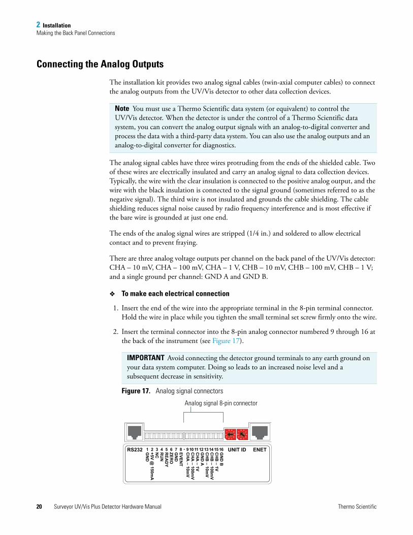
There are three analog voltage outputs per channel on the back panel of the UV/Vis detector: CHA – 10 mV, CHA – 100 mV, CHA – 1 V, CHB – 10 mV, CHB – 100 mV, CHB – 1 V; and a single ground per channel: GND A and GND B.
To make each electrical connection
1. Insert the end of the wire into the appropriate terminal in the 8-pin terminal connector. Hold the wire in place while you tighten the small terminal set screw firmly onto the wire.
2. Insert the terminal connector into the 8-pin analog connector numbered 9 through 16 at the back of the instrument (see Figure 17).
Figure 17. Analog signal connectors
Note You must use a Thermo Scientific data system (or equivalent) to control the UV/Vis detector. When the detector is under the control of a Thermo Scientific data system, you can convert the analog output signals with an analog-to-digital converter and process the data with a third-party data system. You can also use the analog outputs and an analog-to-digital converter for diagnostics.
IMPORTANT Avoid connecting the detector ground terminals to any earth ground on your data system computer. Doing so leads to an increased noise level and a subsequent decrease in sensitivity.
1
2 3
45
6
7890
1
2 3
45
6
7890
1 2 3 4 5 6 7 8RS232 UNIT ID ENETEVENT
GN
DZER
OR
EAD
YR
UN
NC
+5V @ 150m
AG
ND
GN
D B
CH
B _ 1V
CH
B _ 100m
VC
HB
_ 10mV
GN
D A
CH
A _ 1V
CH
A _ 100m
VC
HA
_ 10mV
9 10 11 12 13 14 15 16
Analog signal 8-pin connector
20 Surveyor UV/Vis Plus Detector Hardware Manual Thermo Scientific

2 InstallationMaking the Back Panel Connections
Setting the Analog Output Voltage
You control the analog outputs from the data system by selecting the acquisition wavelengths, bandwidth, rise time, and zero functions of the detector. These outputs are compatible with data collection systems using any of the three different voltages (10 mV, 100 mV, or 1 V) by selecting the appropriate terminal of the analog output terminal connector (see Figure 17).
Making Remote Communications Connections
The UV/Vis detector has the remote communications inputs RUN and ZERO, and the remote communications output EVENT (see Figure 18).
Figure 18. Remote communications signals
RUN Input Signal
The RUN input receives an inject signal from the autosampler, or from a manual injector, and sends a run-start signal to the data system software.
During installation, you must connect the RUN input on the UV/Vis detector to your autosampler or injector output. To make this contact closure connection, do the following:
• If your LC system contains a Surveyor Autosampler Plus, use the 7-connector interconnect cable.
• If your LC system contains a manual injector or another type of autosampler, connect the RUN input on the UV/Vis detector to the autosampler’s Inject Out output, and connect the GND terminal on the UV/Vis detector to the autosampler’s ground terminal.
1
2 3
45
6
7890
1
2 3
45
6
7890
1 2 3 4 5 6 7 8RS232 UNIT ID ENETEVENT
GN
DZER
OR
EAD
YR
UN
NC
+5V @ 150m
AG
ND
GN
D B
CH
B _ 1V
CH
B _ 100m
VC
HB
_ 10mV
GN
D A
CH
A _ 1V
CH
A _ 100m
VC
HA
_ 10mV
9 10 11 12 13 14 15 16
8-pin receptacle for theinterconnect cable
Thermo Scientific Surveyor UV/Vis Plus Detector Hardware Manual 21
2 InstallationMaking the Back Panel Connections
For other autosamplers or injectors, first determine whether the device uses a TTL signal or a relay (a contact-closure), to remotely trigger detectors. Refer to the autosampler or injector documentation to determine whether a TTL signal or relay is used. Then wire the device to the UV/Vis detector, by doing one of the following:
• If the autosampler or injector uses a TTL signal to trigger the run, connect the TTL trigger to the RUN terminal on the UV/Vis detector, and connect the signal ground terminal on the autosampler (or TTL return terminal) to the GND terminal on the UV/Vis detector.
• If the autosampler or injector device output relay consists of a single, normally open terminal and a common ground terminal, connect the normally open terminal to the RUN terminal on the UV/Vis detector, and connect the common ground terminal to the GND terminal on the UV/Vis detector. If both of the relay contacts are electrically isolated from each other and from ground (the device simply closes a contact between the two relay terminals), then connect either one of the relay terminals to the RUN terminal on the UV/Vis detector, and connect the other relay terminal to the GND terminal on the UV/Vis detector.
ZERO Input Signal
The UV/Vis detector does not use the ZERO connection.
EVENT Output Signal
Thermo Scientific data systems do not support this output signal.
Note The ground (GND) terminals (pins 1 and 7) on the back of the UV/Vis detector are tied to a single digital ground. You can use either ground terminal for digital input or output return connections.
22 Surveyor UV/Vis Plus Detector Hardware Manual Thermo Scientific
2 InstallationInstalling the Flow Cell
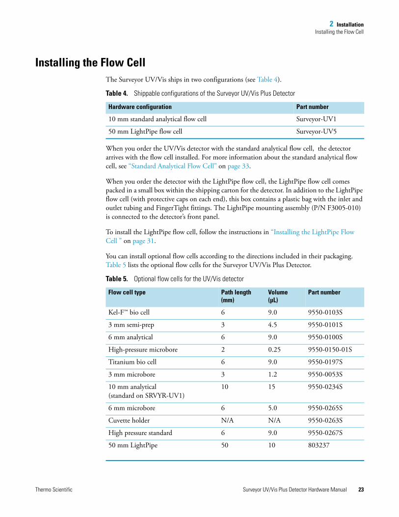
Installing the Flow CellThe Surveyor UV/Vis ships in two configurations (see Table 4).
When you order the UV/Vis detector with the standard analytical flow cell, the detector arrives with the flow cell installed. For more information about the standard analytical flow cell, see “Standard Analytical Flow Cell” on page 33.
When you order the detector with the LightPipe flow cell, the LightPipe flow cell comes packed in a small box within the shipping carton for the detector. In addition to the LightPipe flow cell (with protective caps on each end), this box contains a plastic bag with the inlet and outlet tubing and FingerTight fittings. The LightPipe mounting assembly (P/N F3005-010) is connected to the detector’s front panel.
To install the LightPipe flow cell, follow the instructions in “Installing the LightPipe Flow Cell ” on page 31.
You can install optional flow cells according to the directions included in their packaging. Table 5 lists the optional flow cells for the Surveyor UV/Vis Plus Detector.
Table 4. Shippable configurations of the Surveyor UV/Vis Plus Detector
Hardware configuration Part number
10 mm standard analytical flow cell Surveyor-UV1
50 mm LightPipe flow cell Surveyor-UV5
Table 5. Optional flow cells for the UV/Vis detector
Flow cell type Path length(mm)
Volume(μL)
Part number
Kel-F™ bio cell 6 9.0 9550-0103S
3 mm semi-prep 3 4.5 9550-0101S
6 mm analytical 6 9.0 9550-0100S
High-pressure microbore 2 0.25 9550-0150-01S
Titanium bio cell 6 9.0 9550-0197S
3 mm microbore 3 1.2 9550-0053S
10 mm analytical (standard on SRVYR-UV1)
10 15 9550-0234S
6 mm microbore 6 5.0 9550-0265S
Cuvette holder N/A N/A 9550-0263S
High pressure standard 6 9.0 9550-0267S
50 mm LightPipe 50 10 803237
Thermo Scientific Surveyor UV/Vis Plus Detector Hardware Manual 23
2 InstallationPowering On the Detector for the First Time
Most of the flow cells listed in Table 5 require the standard flow cell cover (P/N 60053-40005). The 50 mm LightPipe flow cell (P/N 803237) requires the LightPipe flow cell cover (P/N 60053-40004). The High Pressure Microbore flow cell requires the microbore flow cell cover (P/N 60053-40006).
Powering On the Detector for the First TimeAfter you have installed the flow cell, the detector is ready to be powered on.
To power on the detector for the first time
1. Ensure that the power switch at the front of the unit is in the Off position (released or out position).
2. Attach the power cord to the power entry module on the back panel of the detector and connect it to the power source.
3. Turn the power on by pushing the power button in to engage it.
When the instrument is powered on, it performs its Start-up diagnostics. After a few seconds, the LEDs on the front of the detector turn solid green. If one or more LEDs flash green or amber, or turn solid amber, there might be a problem. The COMM LED remains amber until the software is started and initiates communication with the detector.
See Chapter 4, “Troubleshooting,” for a complete description of LED status indications. Call your Thermo Fisher Scientific Service Representative if you require assistance.
IMPORTANT If you are using a previous version of the LightPipe flow cell that has natural PEEK end caps, make sure the flow cell cover is in place before turning the power on. When the instrument is powered on, it performs its Start-up diagnostics. Ambient light can affect these diagnostics.
IMPORTANT Install the flow cell cover, which minimizes thermal fluctuations, before you use the detector for data acquisition.
24 Surveyor UV/Vis Plus Detector Hardware Manual Thermo Scientific
3
Maintenance
Proper maintenance ensures the optimum performance of the UV/Vis detector. You are responsible for maintaining your detector by properly performing the maintenance procedures on a regular basis. If you have any questions on proper maintenance, or would like to arrange for a preventive maintenance program, contact your Thermo Fisher Scientific field service engineer.
To maintain your UV/Vis detector, follow the routine maintenance procedures in this chapter.
Contents
• Recommended Routine Maintenance
• Preventive Maintenance
• Maintenance Tools
• Cleaning Detector External Surfaces
• LightPipe Flow Cell
• Standard Analytical Flow Cell
• Cleaning the Flow Cells
• Lamp Maintenance
Thermo Scientific Surveyor UV/Vis Plus Detector Hardware Manual 25
3 MaintenanceRecommended Routine Maintenance
Recommended Routine MaintenanceTable 6 lists recommendations for routine maintenance of the UV/Vis detector. Use the table as a basis for developing your maintenance program in accordance with your company practices.
Preventive MaintenanceIn addition to standard practices for laboratory cleanliness, Thermo Fisher Scientific recommends the following preventive measures:
• Use only high-purity liquid in all “wetted surface” contact areas for the analysis, for flushing, and for cleaning. Use only high-purity gases when drying the same areas.
• Thoroughly flush all plumbing (including the flow cell) after each use. Remember that water is the recommended “last contact” liquid.
Keep the flow cell absolutely clean to maintain low-noise operation. Organic films and residues are major causes of noise. Also consider the analytical solutions passing through the flow cell. If they pose a possible contamination problem, flush the flow cell with water or methanol. If this does not remove the contamination, clean the flow cell with a dilute solution of nitric acid, followed by a water rinse.
• Thoroughly flush and clean all peripheral plumbing, pumps, and so on, before connecting them to the flow cell.
• To avoid particulate contamination and fluid path blockage, maximize the use of filtration.
• Avoid leaving buffers standing in the flow cell for long periods. Plan your use to minimize standing time between runs.
Table 6. Recommended routine maintenance
Procedure Interval
Cleaning external surfaces As needed. See “Cleaning Detector External Surfaces” on page 27.
Cleaning the flow cell As needed.a See “Cleaning the Flow Cells” on page 36.
a Good laboratory practices dictate flushing the flow cell with clean solvent after every use. This will greatly reduce how often you need to clean it.
Lamp replacement
Deuterium (D2)
Replace the deuterium lamp when the detector noise reaches an unacceptable level. See “Removing the Deuterium Lamp” on page 40.
The useful lamp lifetime is approximately 2000 hours.
Tungsten (W)
Every 2500 hours or as required. See “Removing the Tungsten Lamp ” on page 43.
26 Surveyor UV/Vis Plus Detector Hardware Manual Thermo Scientific
3 MaintenanceMaintenance Tools
Maintenance ToolsMaintaining the UV/Vis detector requires these tools:
• narrow-tip, flat-bladed screwdriver (2 mm wide)
• #2 Phillips screwdriver
• 1/4 in. open-end wrench
• 1/8 in. hex wrench (supplied)
• 3/32 in. hex wrench (supplied)
• 9/64 in. hex wrench (supplied)
Cleaning Detector External SurfacesKeep the external surfaces of the detector clean and dry. To clean the outside of the detector, wipe it with a dust-free cloth or a damp cloth (moistened with water only) to remove dirt or stains.
LightPipe Flow CellTo remove or install the LightPipe flow cell, follow these procedures:
• Removing the LightPipe Flow Cell
• Storing the LightPipe Flow Cell
• Installing the LightPipe Mounting Assembly
• Installing the LightPipe Flow Cell
Removing the LightPipe Flow Cell
To remove the LightPipe flow cell from the mounting assembly
1. Open the front doors of the detector.
2. Using a 1/8 in. hex wrench (supplied), unscrew the LightPipe cover retention screw. Then remove the LightPipe cover. See Figure 19.
CAUTION Do not disassemble the LightPipe housing or tighten the screws on the housing. Doing so will damage the LightPipe flow cell. Thermo Fisher Scientific cannot be held responsible for any damage done to the LightPipe flow cell by attempts to disassemble the housing or to tighten the screws. Contact your Thermo Fisher Scientific Service Representative with any questions regarding LightPipe flow cell maintenance or service.
Thermo Scientific Surveyor UV/Vis Plus Detector Hardware Manual 27

3 MaintenanceLightPipe Flow Cell
Figure 19. Front panel of the UV/Vis detector with the LightPipe and lamp covers
3. Using the 3/32 in. hex wrench (supplied), loosen and remove the two photodiode mount retention screws. See Figure 20.
Figure 20. Photodiode assembly, showing two mounting screws
4. Carefully pull the photodiode mount straight back and off the LightPipe mounting assembly. Rest the photodiode mount out of the way inside the detector housing or on the benchtop.
5. Loosen the thumbscrew holding the retention block to the LightPipe retention bar. See Figure 21.
Lamp cover retention screw
LightPipe cover retention screw
CAUTION Do not touch the surface of the photodiode. When removing the photodiode mount, be sure to place the mount where the photodiode will not get dirty or scratched.
Photodiode assembly mounting screws
28 Surveyor UV/Vis Plus Detector Hardware Manual Thermo Scientific
3 MaintenanceLightPipe Flow Cell
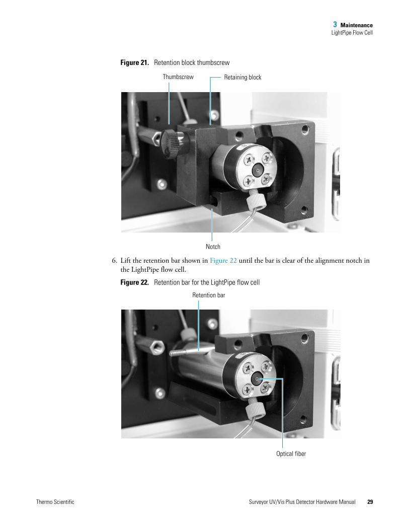
Figure 21. Retention block thumbscrew
6. Lift the retention bar shown in Figure 22 until the bar is clear of the alignment notch in the LightPipe flow cell.
Figure 22. Retention bar for the LightPipe flow cell
Thumbscrew Retaining block
Notch
Retention bar
Optical fiber
Thermo Scientific Surveyor UV/Vis Plus Detector Hardware Manual 29
3 MaintenanceLightPipe Flow Cell
7. Carefully remove the LightPipe flow cell from the LightPipe mounting assembly without touching the ends of the LightPipe flow cell.
Storing the LightPipe Flow Cell
To store the LightPipe flow cell
1. Remove the FingerTight fittings and any attached tubing.
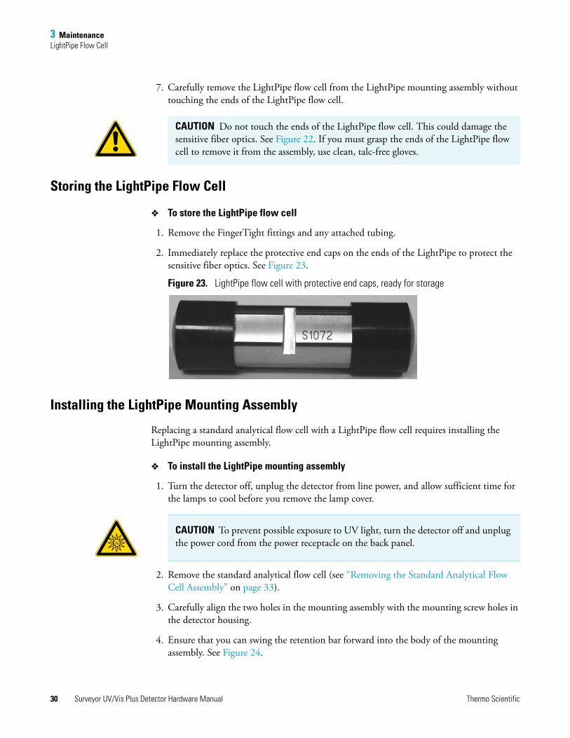
2. Immediately replace the protective end caps on the ends of the LightPipe to protect the sensitive fiber optics. See Figure 23.
Figure 23. LightPipe flow cell with protective end caps, ready for storage
Installing the LightPipe Mounting Assembly
Replacing a standard analytical flow cell with a LightPipe flow cell requires installing the LightPipe mounting assembly.
To install the LightPipe mounting assembly
1. Turn the detector off, unplug the detector from line power, and allow sufficient time for the lamps to cool before you remove the lamp cover.
2. Remove the standard analytical flow cell (see “Removing the Standard Analytical Flow Cell Assembly” on page 33).
3. Carefully align the two holes in the mounting assembly with the mounting screw holes in the detector housing.
4. Ensure that you can swing the retention bar forward into the body of the mounting assembly. See Figure 24.
CAUTION Do not touch the ends of the LightPipe flow cell. This could damage the sensitive fiber optics. See Figure 22. If you must grasp the ends of the LightPipe flow cell to remove it from the assembly, use clean, talc-free gloves.
CAUTION To prevent possible exposure to UV light, turn the detector off and unplug the power cord from the power receptacle on the back panel.UV
30 Surveyor UV/Vis Plus Detector Hardware Manual Thermo Scientific
3 MaintenanceLightPipe Flow Cell
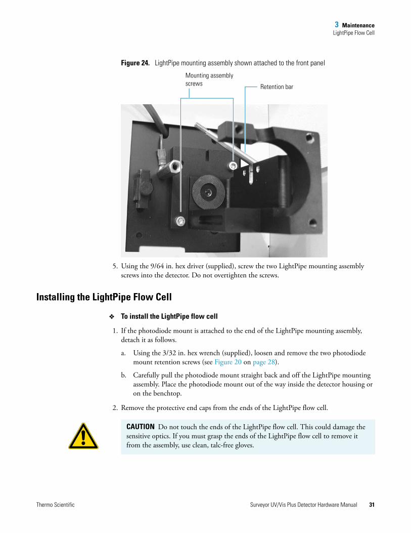
Figure 24. LightPipe mounting assembly shown attached to the front panel
5. Using the 9/64 in. hex driver (supplied), screw the two LightPipe mounting assembly screws into the detector. Do not overtighten the screws.
Installing the LightPipe Flow Cell
To install the LightPipe flow cell
1. If the photodiode mount is attached to the end of the LightPipe mounting assembly, detach it as follows.
a. Using the 3/32 in. hex wrench (supplied), loosen and remove the two photodiode mount retention screws (see Figure 20 on page 28).
b. Carefully pull the photodiode mount straight back and off the LightPipe mounting assembly. Place the photodiode mount out of the way inside the detector housing or on the benchtop.
2. Remove the protective end caps from the ends of the LightPipe flow cell.
Retention bar
Mounting assembly screws
CAUTION Do not touch the ends of the LightPipe flow cell. This could damage the sensitive optics. If you must grasp the ends of the LightPipe flow cell to remove it from the assembly, use clean, talc-free gloves.
Thermo Scientific Surveyor UV/Vis Plus Detector Hardware Manual 31
3 MaintenanceLightPipe Flow Cell
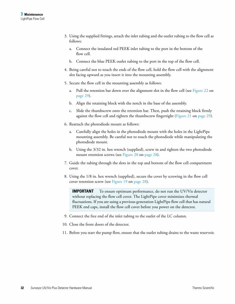
3. Using the supplied fittings, attach the inlet tubing and the outlet tubing to the flow cell as follows:
a. Connect the insulated red PEEK inlet tubing to the port in the bottom of the flow cell.
b. Connect the blue PEEK outlet tubing to the port in the top of the flow cell.
4. Being careful not to touch the ends of the flow cell, hold the flow cell with the alignment slot facing upward as you insert it into the mounting assembly.
5. Secure the flow cell in the mounting assembly as follows:
a. Pull the retention bar down over the alignment slot in the flow cell (see Figure 22 on page 29).
b. Align the retaining block with the notch in the base of the assembly.
c. Slide the thumbscrew onto the retention bar. Then, push the retaining block firmly against the flow cell and tighten the thumbscrew fingertight (Figure 21 on page 29).
6. Reattach the photodiode mount as follows:
a. Carefully align the holes in the photodiode mount with the holes in the LightPipe mounting assembly. Be careful not to touch the photodiode while manipulating the photodiode mount.
b. Using the 3/32 in. hex wrench (supplied), screw in and tighten the two photodiode mount retention screws (see Figure 20 on page 28).
7. Guide the tubing through the slots in the top and bottom of the flow cell compartment cover.
8. Using the 1/8 in. hex wrench (supplied), secure the cover by screwing in the flow cell cover retention screw (see Figure 19 on page 28).
9. Connect the free end of the inlet tubing to the outlet of the LC column.
10. Close the front doors of the detector.
11. Before you start the pump flow, ensure that the outlet tubing drains to the waste reservoir.
IMPORTANT To ensure optimum performance, do not run the UV/Vis detector without replacing the flow cell cover. The LightPipe cover minimizes thermal fluctuations. If you are using a previous generation LightPipe flow cell that has natural PEEK end caps, install the flow cell cover before you power on the detector.
32 Surveyor UV/Vis Plus Detector Hardware Manual Thermo Scientific
3 MaintenanceStandard Analytical Flow Cell
Standard Analytical Flow CellTo remove or install the standard analytical flow cell, follow these topics:
• Removing the Standard Analytical Flow Cell Assembly
• Installing the Standard Analytical Flow Cell
Removing the Standard Analytical Flow Cell Assembly
To clean or replace the standard analytical flow cell, remove it from the UV/Vis detector.
To remove the standard analytical flow cell
1. Turn the detector off and unplug the detector from line power.
2. Open the front doors of the detector.
The flow cell assembly is located behind the flow cell cover.
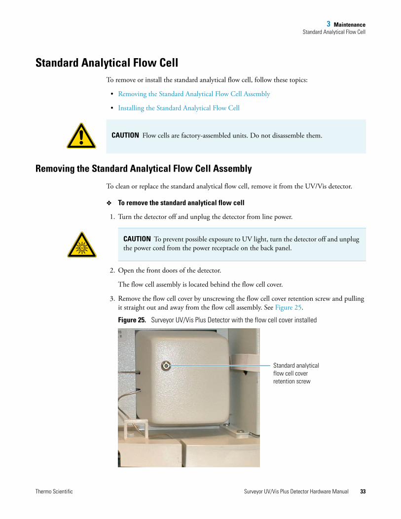
3. Remove the flow cell cover by unscrewing the flow cell cover retention screw and pulling it straight out and away from the flow cell assembly. See Figure 25.
Figure 25. Surveyor UV/Vis Plus Detector with the flow cell cover installed
CAUTION Flow cells are factory-assembled units. Do not disassemble them.
CAUTION To prevent possible exposure to UV light, turn the detector off and unplug the power cord from the power receptacle on the back panel.UV
Standard analytical flow cell cover retention screw
Thermo Scientific Surveyor UV/Vis Plus Detector Hardware Manual 33
3 MaintenanceStandard Analytical Flow Cell
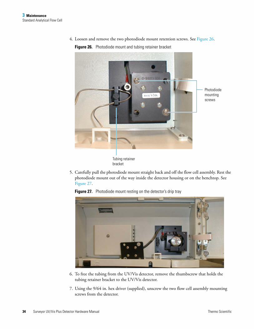
4. Loosen and remove the two photodiode mount retention screws. See Figure 26.
Figure 26. Photodiode mount and tubing retainer bracket
5. Carefully pull the photodiode mount straight back and off the flow cell assembly. Rest the photodiode mount out of the way inside the detector housing or on the benchtop. See Figure 27.
Figure 27. Photodiode mount resting on the detector’s drip tray
6. To free the tubing from the UV/Vis detector, remove the thumbscrew that holds the tubing retainer bracket to the UV/Vis detector.
7. Using the 9/64 in. hex driver (supplied), unscrew the two flow cell assembly mounting screws from the detector.
Photodiode mounting screws
Tubing retainer bracket
34 Surveyor UV/Vis Plus Detector Hardware Manual Thermo Scientific
3 MaintenanceStandard Analytical Flow Cell
8. Carefully pull the assembly out of the UV/Vis detector and toward you to remove it from the detector.
9. Disconnect the flow cell inlet tube from the column and disconnect the flow cell outlet tubing from the waste reservoir.
Installing the Standard Analytical Flow Cell
To install the standard analytical flow cell
1. With the inlet tube on the bottom left and the flow cell slot on top, slide the flow cell assembly into the detector and under the alignment pin.
2. Replace the two flow cell assembly mounting screws.
3. Align the photodiode mount with the flow cell assembly so that the two holes with nylon washers align with the photodiode mounting posts on the flow cell assembly.
4. Using the 9/64 in. hex driver, install the two photodiode mount retention screws.
5. Connect the inlet tubing to the chromatographic column and the outlet tubing to the waste reservoir.
6. Replace the tubing retainer bracket and tighten the thumbscrew just enough to hold the tubing in place.
7. Guide the tubing through the slots in the flow cell cover, and then securing the cover with the flow cell cover mounting screw.
8. Connect the power cord to the power entry module on the detector’s back panel.
Thermo Scientific Surveyor UV/Vis Plus Detector Hardware Manual 35
3 MaintenanceCleaning the Flow Cells
Cleaning the Flow CellsThe exterior and interior surfaces of the flow cell can become contaminated. Flow cell contamination is usually caused by precipitation or by solubility problems, such as when the quality of your mobile phase varies or the cleanliness of your samples varies. Signs of a contaminated flow cell are increased baseline noise, signal spiking, erratic or drifting baselines, low light intensity, or increased backpressure.
For other flow cell problems, such as a cracked window or leaks that occur in locations other than at the inlet/outlet fittings, contact your Thermo Fisher Scientific service representative.
To clean the flow cell, follow these procedures:
• Cleaning the Flow Cell with Organic Solvents
• Cleaning the Flow Cell with Nitric Acid
Cleaning the Flow Cell with Organic Solvents
If you suspect that the flow cell needs to be cleaned, try using organic solvents to clean it.
To clean the flow cell with an organic solvent
1. Remove the column from the chromatographic system to avoid column degradation.
2. Connect the flow cell inlet directly to the chromatographic pump outlet.
3. If necessary, flush the flow cell with water to prevent a reaction between the last solvent used in the chromatographic system and the cleaning solvent that you will use to clean the flow cell.
4. Flush the flow cell with 40 to 50 mL of cleaning solvent, for example, isopropanol or methanol.
5. Flush the flow cell with water to prevent a reaction between the cleaning solvent and the mobile phase that is used in your chromatographic application.
IMPORTANT Ensure that the cleaning solvents you plan to use are miscible with the solvent already present in the flow cell and pump. Isopropanol is a good cleaning solvent for most applications. If the last solvent in the pump was an aqueous buffer solution, be sure to pump 25 to 40 mL of HPLC-grade water (or its equivalent) through the system to remove any salts before you flush the pump with the cleaning solvents.
CAUTION Do not use a syringe to force solvent through the flow cell. Pressurizing the flow cell can cause a leak or rupture and result in a dangerous and uncontrolled spraying of solvent.
36 Surveyor UV/Vis Plus Detector Hardware Manual Thermo Scientific
3 MaintenanceCleaning the Flow Cells
Cleaning the Flow Cell with Nitric Acid
Methanol or isopropanol is generally sufficient for cleaning a flow cell. However, if the flow cell remains contaminated after flushing it with organic solvents, remove the flow cell from the detector and clean it with nitric acid.
To clean the flow cell with nitric acid
1. Remove the flow cell from the detector housing. See “Removing the LightPipe Flow Cell” on page 27 or “Removing the Standard Analytical Flow Cell Assembly” on page 33.
Removing the flow cell from the detector prevents possible leaks from harming the mechanical and electronic components of the detector.
2. Ensure that the column is removed from the chromatographic system to avoid column degradation.
3. Connect the outlet from the chromatographic pump to the flow cell inlet.
4. Flush the cell with water to prevent a reaction between the last solvent used in the chromatographic system and the cleaning solution.
5. Prepare a 20% (vol/vol) solution of nitric acid in HPLC-grade water.
6. Pump the nitric acid solution through the flow cell.
CAUTION Nitric acid is a strong oxidizing acid, and it can react vigorously with alcohols (especially methanol). Be sure to wear protective clothing and eye protection and adhere to your company’s safety procedures for the proper handling and disposal of corrosive acids. Flush the flow cell with water to remove all traces of alcohol before flushing it with nitric acid.
CAUTION If cleaning the flow cell does not remove the contamination, replace the flow cell. Do not attempt to repair the flow cell by disassembling it.
CAUTION Do not use a syringe to force acid solutions through the flow cell. Pressurizing the flow cell can cause a leak or rupture and result in a dangerous and uncontrolled acid spray.
CAUTION Before you pump cleaning solutions through the flow cell, do the following:
• Remove the LC column from the chromatographic system.
• Pump HPLC-grade water through the flow cell.
Thermo Scientific Surveyor UV/Vis Plus Detector Hardware Manual 37
3 MaintenanceLamp Maintenance
7. To remove all traces of nitric acid, pump 25 to 40 mL of water through the flow cell. Monitor the pH of the outlet stream of the flow cell to ensure that you have completely flushed the acid out of the flow cell.
8. Reinstall the flow cell. See “Installing the LightPipe Flow Cell ” on page 31 or “Installing the Standard Analytical Flow Cell” on page 35.
Lamp MaintenanceThe light output from the deuterium lamp decreases with age, which results in increased baseline noise. If the noise level on your detector output signal is unacceptable and cleaning the flow cell does not help, use the data system’s diagnostic features to determine the cause of the problem. If the light output becomes too low, replace the deuterium lamp. The light output from the tungsten lamp is relatively stable as the lamp ages.
The detector keeps track of the number of hours each lamp has been operating. The deuterium lamp has a lifetime of approximately 2000 hours and the tungsten lamp has a lifetime of approximately 2500 hours. Lamp lifetime varies depending on the application.
To access the lamps, open the front doors of the detector. The deuterium and tungsten lamps are located in the housing on the left. The lamps are supplied pre-aligned in their individual assemblies to make them easy to install and align.
To replace the detector’s lamps, follow these procedures:
• Checking the Deuterium Lamp Usage Hours and Replacing the Lamp
• Replacing the Tungsten Lamp
Checking the Deuterium Lamp Usage Hours and Replacing the Lamp
To access the deuterium lamp chronometer and replace the lamp if necessary, follow these procedures:
• Accessing the Deuterium Lamp and Reading Its Chronometer
• Removing the Deuterium Lamp
• Installing a New Deuterium Lamp
IMPORTANT Never loosen the screws that hold the lamp to its assembly or attempt to rotate or move the lamp up or down in the assembly. Either of these actions can cause a loss of alignment and degrade the system performance.
38 Surveyor UV/Vis Plus Detector Hardware Manual Thermo Scientific
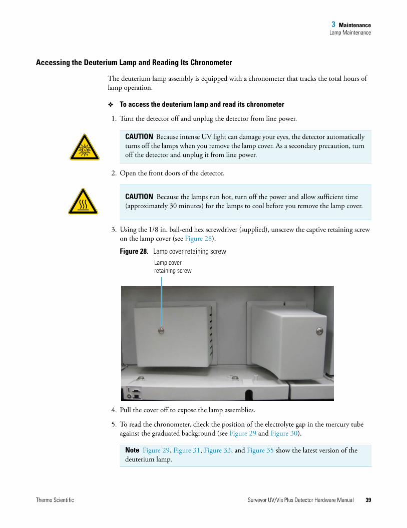
3 MaintenanceLamp Maintenance
Accessing the Deuterium Lamp and Reading Its Chronometer
The deuterium lamp assembly is equipped with a chronometer that tracks the total hours of lamp operation.
To access the deuterium lamp and read its chronometer
1. Turn the detector off and unplug the detector from line power.
2. Open the front doors of the detector.
3. Using the 1/8 in. ball-end hex screwdriver (supplied), unscrew the captive retaining screw on the lamp cover (see Figure 28).
Figure 28. Lamp cover retaining screw
4. Pull the cover off to expose the lamp assemblies.
5. To read the chronometer, check the position of the electrolyte gap in the mercury tube against the graduated background (see Figure 29 and Figure 30).
CAUTION Because intense UV light can damage your eyes, the detector automatically turns off the lamps when you remove the lamp cover. As a secondary precaution, turn off the detector and unplug it from line power.
UV
CAUTION Because the lamps run hot, turn off the power and allow sufficient time (approximately 30 minutes) for the lamps to cool before you remove the lamp cover.
Note Figure 29, Figure 31, Figure 33, and Figure 35 show the latest version of the deuterium lamp.
Lamp cover retaining screw
Thermo Scientific Surveyor UV/Vis Plus Detector Hardware Manual 39
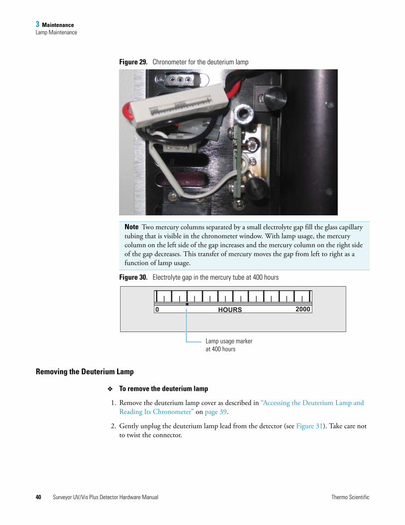
3 MaintenanceLamp Maintenance
Figure 29. Chronometer for the deuterium lamp
Figure 30. Electrolyte gap in the mercury tube at 400 hours
Removing the Deuterium Lamp
To remove the deuterium lamp
1. Remove the deuterium lamp cover as described in “Accessing the Deuterium Lamp and Reading Its Chronometer” on page 39.
2. Gently unplug the deuterium lamp lead from the detector (see Figure 31). Take care not to twist the connector.
Note Two mercury columns separated by a small electrolyte gap fill the glass capillary tubing that is visible in the chronometer window. With lamp usage, the mercury column on the left side of the gap increases and the mercury column on the right side of the gap decreases. This transfer of mercury moves the gap from left to right as a function of lamp usage.
0 2000HOURS
Lamp usage marker at 400 hours
40 Surveyor UV/Vis Plus Detector Hardware Manual Thermo Scientific
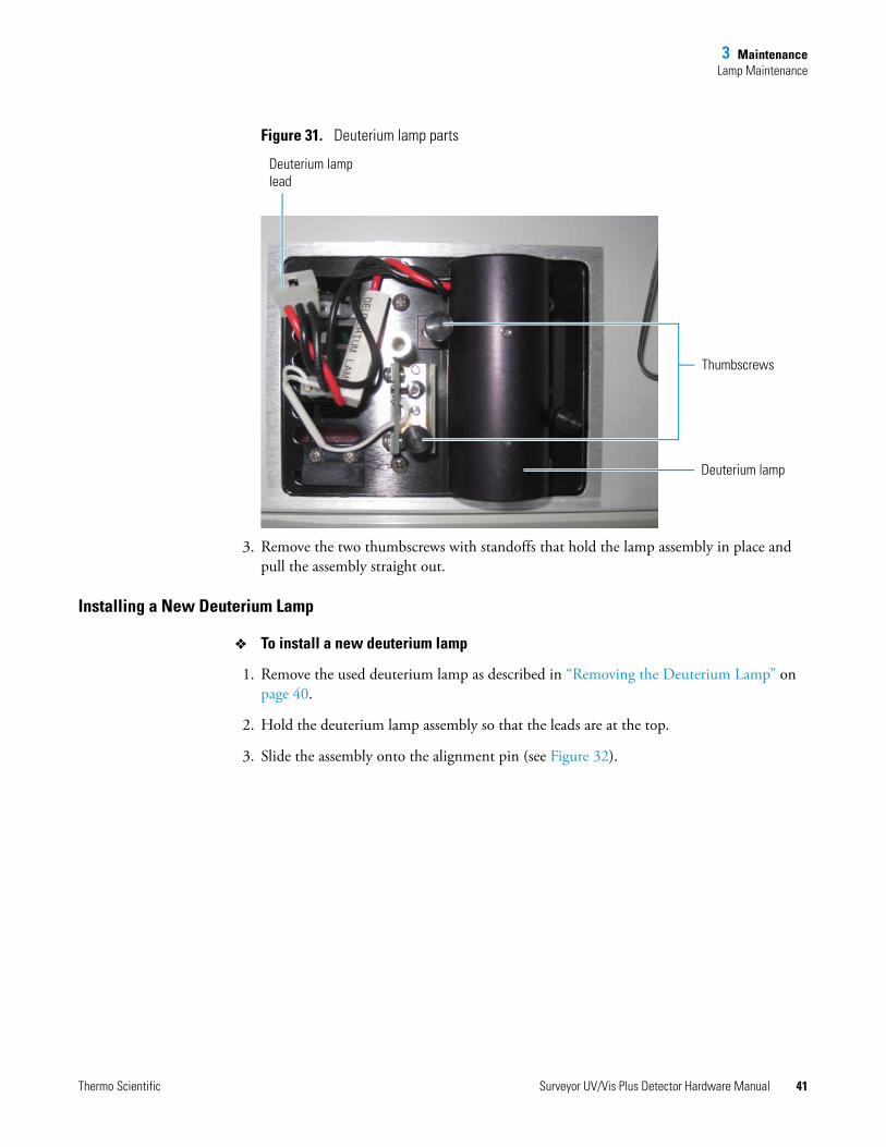
3 MaintenanceLamp Maintenance
Figure 31. Deuterium lamp parts
3. Remove the two thumbscrews with standoffs that hold the lamp assembly in place and pull the assembly straight out.
Installing a New Deuterium Lamp
To install a new deuterium lamp
1. Remove the used deuterium lamp as described in “Removing the Deuterium Lamp” on page 40.
2. Hold the deuterium lamp assembly so that the leads are at the top.
3. Slide the assembly onto the alignment pin (see Figure 32).
Deuterium lamp lead
Thumbscrews
Deuterium lamp
Thermo Scientific Surveyor UV/Vis Plus Detector Hardware Manual 41
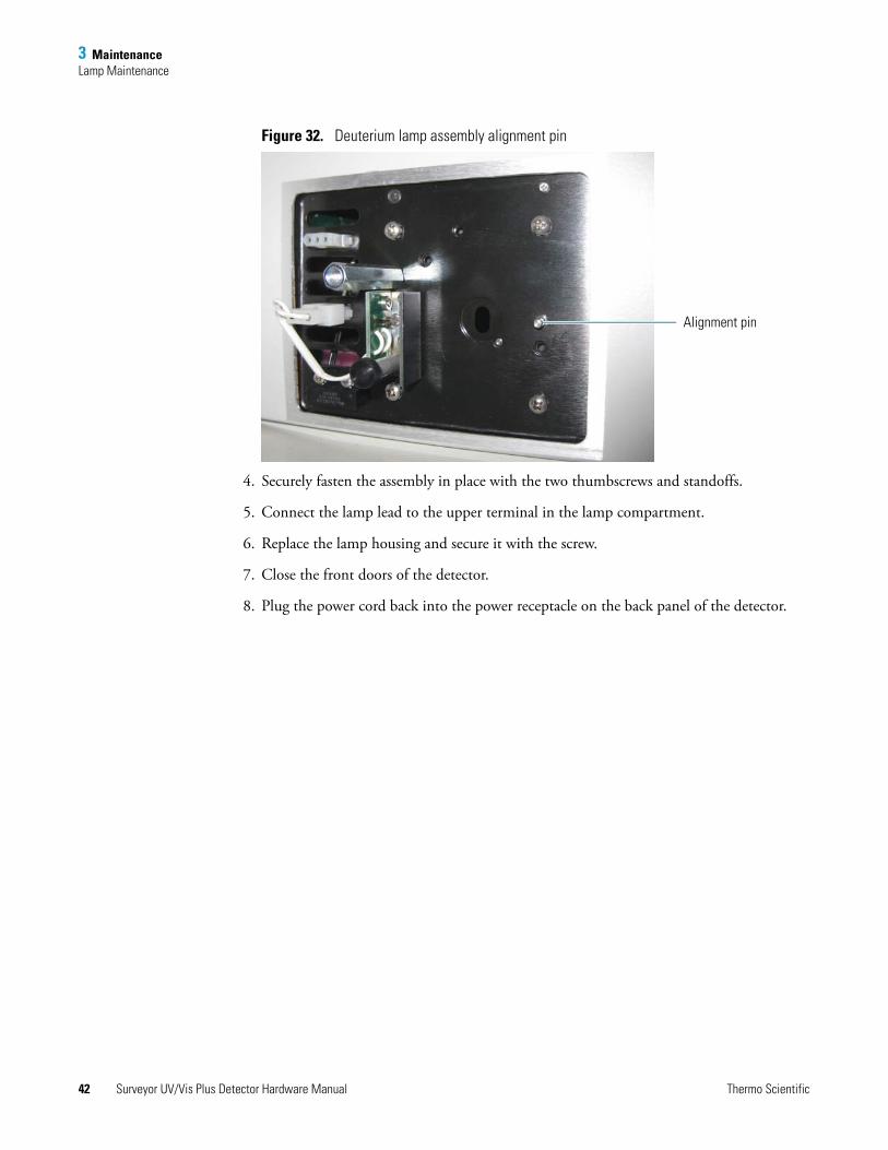
3 MaintenanceLamp Maintenance
Figure 32. Deuterium lamp assembly alignment pin
4. Securely fasten the assembly in place with the two thumbscrews and standoffs.
5. Connect the lamp lead to the upper terminal in the lamp compartment.
6. Replace the lamp housing and secure it with the screw.
7. Close the front doors of the detector.
8. Plug the power cord back into the power receptacle on the back panel of the detector.
Alignment pin
42 Surveyor UV/Vis Plus Detector Hardware Manual Thermo Scientific
3 MaintenanceLamp Maintenance
Replacing the Tungsten Lamp
To replace the tungsten lamp, follow these steps:
1. Removing the Tungsten Lamp
2. Installing a New Tungsten Lamp
Removing the Tungsten Lamp
To remove the tungsten lamp
1. Turn the detector off, unplug the power cord from the power receptacle on the back panel, and allow sufficient time for the lamps to cool before you remove the lamp cover.
2. Open the front doors of the detector.
3. Using the 1/8 in. ball-end hex screwdriver (supplied), unscrew the captive retaining screw on the lamp cover (see Figure 28 on page 39).
4. Pull the cover straight back to expose the lamp assemblies.
5. Gently unplug the tungsten lamp lead from the detector (see Figure 31).
Take care not to twist the connector.
CAUTION Because intense UV light can damage your eyes, the detector automatically turns off the lamps when you remove the lamp cover. As a secondary precaution, turn off the detector and unplug it from line power.
UV
CAUTION Because the lamps run hot, turn off the power and allow sufficient time (approximately 30 minutes) for the lamps to cool before you remove the lamp cover.
Thermo Scientific Surveyor UV/Vis Plus Detector Hardware Manual 43
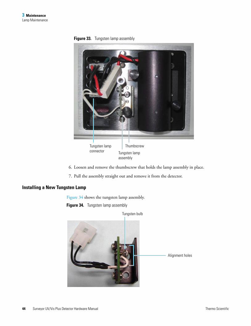
3 MaintenanceLamp Maintenance
Figure 33. Tungsten lamp assembly
6. Loosen and remove the thumbscrew that holds the lamp assembly in place.
7. Pull the assembly straight out and remove it from the detector.
Installing a New Tungsten Lamp
Figure 34 shows the tungsten lamp assembly.
Figure 34. Tungsten lamp assembly
Thumbscrew
Tungsten lamp assembly
Tungsten lamp connector
Alignment holes
Tungsten bulb
44 Surveyor UV/Vis Plus Detector Hardware Manual Thermo Scientific
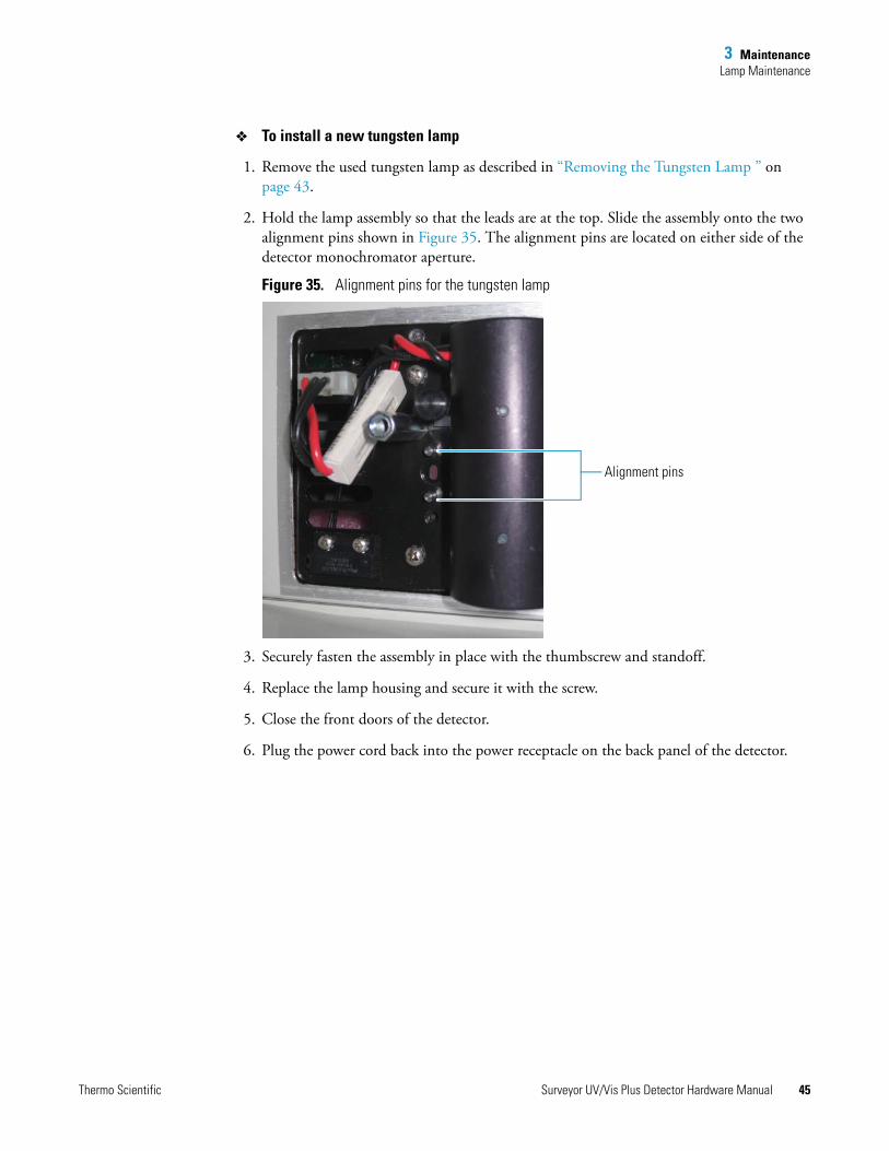
3 MaintenanceLamp Maintenance
To install a new tungsten lamp
1. Remove the used tungsten lamp as described in “Removing the Tungsten Lamp ” on page 43.
2. Hold the lamp assembly so that the leads are at the top. Slide the assembly onto the two alignment pins shown in Figure 35. The alignment pins are located on either side of the detector monochromator aperture.
Figure 35. Alignment pins for the tungsten lamp
3. Securely fasten the assembly in place with the thumbscrew and standoff.
4. Replace the lamp housing and secure it with the screw.
5. Close the front doors of the detector.
6. Plug the power cord back into the power receptacle on the back panel of the detector.
Alignment pins
Thermo Scientific Surveyor UV/Vis Plus Detector Hardware Manual 45

4
Troubleshooting
To troubleshoot possible detector and chromatographic system problems, use the information in this chapter. The information is organized in a table of symptoms, possible causes, and remedies (see Table 7). Because many of the problems attributed to the detector might actually be due to other components in the chromatographic system, the table also includes references and potential solutions to these types of problems. To aid in troubleshooting errors, Table 8 lists some common error messages and numeric codes.
Contents
• Detector-Related Problems
• Error Messages
Thermo Scientific Surveyor UV/Vis Plus Detector Hardware Manual 47
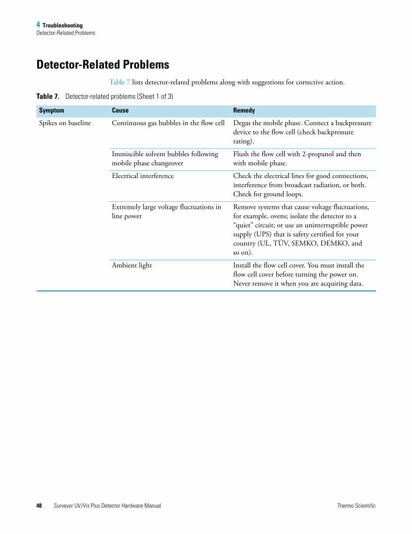
4 TroubleshootingDetector-Related Problems
Detector-Related ProblemsTable 7 lists detector-related problems along with suggestions for corrective action.
Table 7. Detector-related problems (Sheet 1 of 3)
Symptom Cause Remedy
Spikes on baseline Continuous gas bubbles in the flow cell Degas the mobile phase. Connect a backpressure device to the flow cell (check backpressure rating).
Immiscible solvent bubbles following mobile phase changeover
Flush the flow cell with 2-propanol and then with mobile phase.
Electrical interference Check the electrical lines for good connections, interference from broadcast radiation, or both. Check for ground loops.
Extremely large voltage fluctuations in line power
Remove systems that cause voltage fluctuations, for example, ovens; isolate the detector to a “quiet” circuit; or use an uninterruptible power supply (UPS) that is safety certified for your country (UL, TÜV, SEMKO, DEMKO, and so on).
Ambient light Install the flow cell cover. You must install the flow cell cover before turning the power on. Never remove it when you are acquiring data.
48 Surveyor UV/Vis Plus Detector Hardware Manual Thermo Scientific
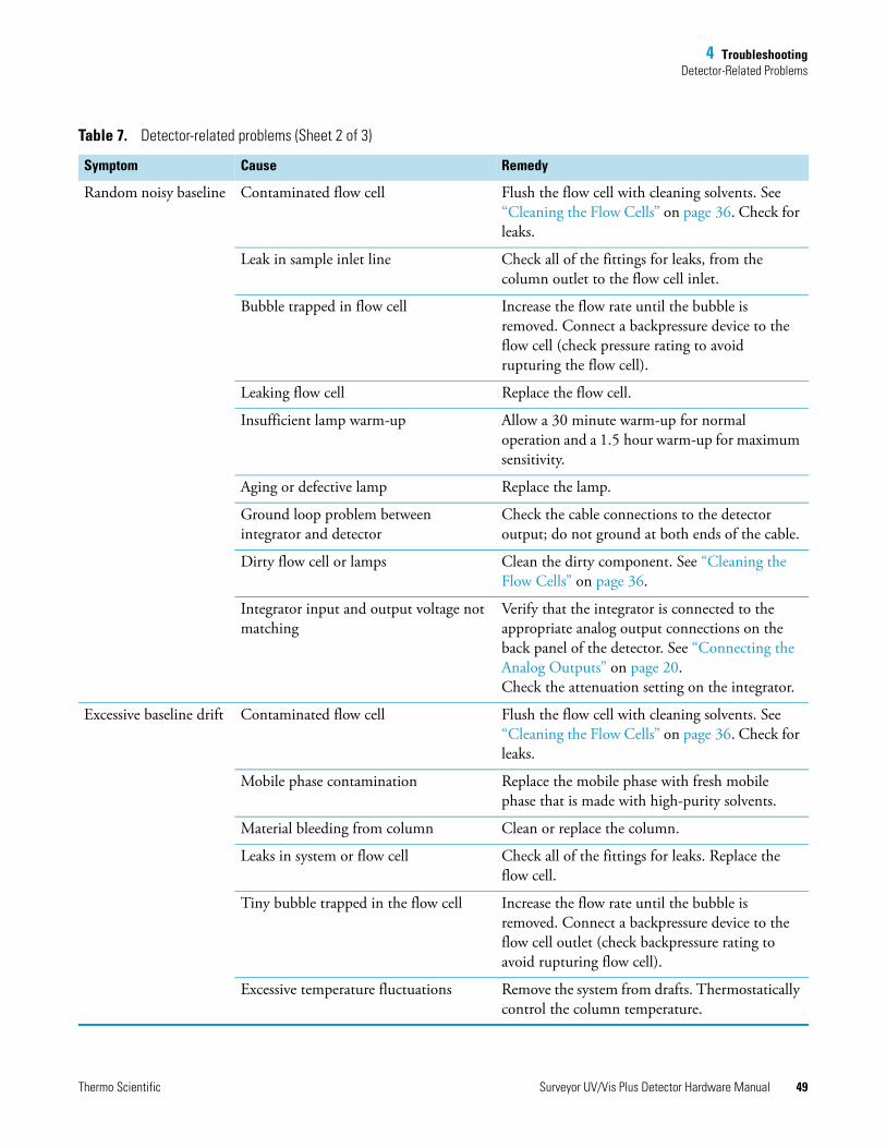
4 TroubleshootingDetector-Related Problems
Random noisy baseline Contaminated flow cell Flush the flow cell with cleaning solvents. See “Cleaning the Flow Cells” on page 36. Check for leaks.
Leak in sample inlet line Check all of the fittings for leaks, from the column outlet to the flow cell inlet.
Bubble trapped in flow cell Increase the flow rate until the bubble is removed. Connect a backpressure device to the flow cell (check pressure rating to avoid rupturing the flow cell).
Leaking flow cell Replace the flow cell.
Insufficient lamp warm-up Allow a 30 minute warm-up for normal operation and a 1.5 hour warm-up for maximum sensitivity.
Aging or defective lamp Replace the lamp.
Ground loop problem between integrator and detector
Check the cable connections to the detector output; do not ground at both ends of the cable.
Dirty flow cell or lamps Clean the dirty component. See “Cleaning the Flow Cells” on page 36.
Integrator input and output voltage not matching
Verify that the integrator is connected to the appropriate analog output connections on the back panel of the detector. See “Connecting the Analog Outputs” on page 20. Check the attenuation setting on the integrator.
Excessive baseline drift Contaminated flow cell Flush the flow cell with cleaning solvents. See “Cleaning the Flow Cells” on page 36. Check for leaks.
Mobile phase contamination Replace the mobile phase with fresh mobile phase that is made with high-purity solvents.
Material bleeding from column Clean or replace the column.
Leaks in system or flow cell Check all of the fittings for leaks. Replace the flow cell.
Tiny bubble trapped in the flow cell Increase the flow rate until the bubble is removed. Connect a backpressure device to the flow cell outlet (check backpressure rating to avoid rupturing flow cell).
Excessive temperature fluctuations Remove the system from drafts. Thermostatically control the column temperature.
Table 7. Detector-related problems (Sheet 2 of 3)
Symptom Cause Remedy
Thermo Scientific Surveyor UV/Vis Plus Detector Hardware Manual 49
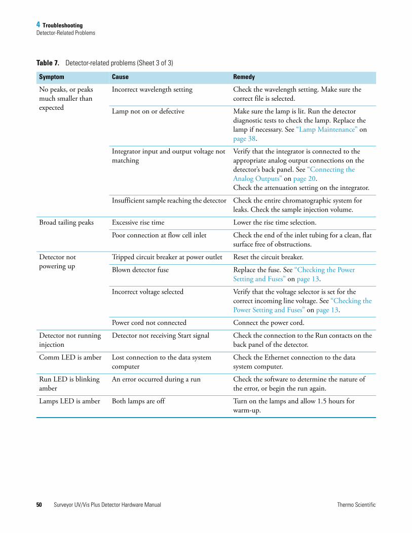
4 TroubleshootingDetector-Related Problems
No peaks, or peaks much smaller than expected
Incorrect wavelength setting Check the wavelength setting. Make sure the correct file is selected.
Lamp not on or defective Make sure the lamp is lit. Run the detector diagnostic tests to check the lamp. Replace the lamp if necessary. See “Lamp Maintenance” on page 38.
Integrator input and output voltage not matching
Verify that the integrator is connected to the appropriate analog output connections on the detector’s back panel. See “Connecting the Analog Outputs” on page 20. Check the attenuation setting on the integrator.
Insufficient sample reaching the detector Check the entire chromatographic system for leaks. Check the sample injection volume.
Broad tailing peaks Excessive rise time Lower the rise time selection.
Poor connection at flow cell inlet Check the end of the inlet tubing for a clean, flat surface free of obstructions.
Detector not powering up
Tripped circuit breaker at power outlet Reset the circuit breaker.
Blown detector fuse Replace the fuse. See “Checking the Power Setting and Fuses” on page 13.
Incorrect voltage selected Verify that the voltage selector is set for the correct incoming line voltage. See “Checking the Power Setting and Fuses” on page 13.
Power cord not connected Connect the power cord.
Detector not running injection
Detector not receiving Start signal Check the connection to the Run contacts on the back panel of the detector.
Comm LED is amber Lost connection to the data system computer
Check the Ethernet connection to the data system computer.
Run LED is blinking amber
An error occurred during a run Check the software to determine the nature of the error, or begin the run again.
Lamps LED is amber Both lamps are off Turn on the lamps and allow 1.5 hours for warm-up.
Table 7. Detector-related problems (Sheet 3 of 3)
Symptom Cause Remedy
50 Surveyor UV/Vis Plus Detector Hardware Manual Thermo Scientific
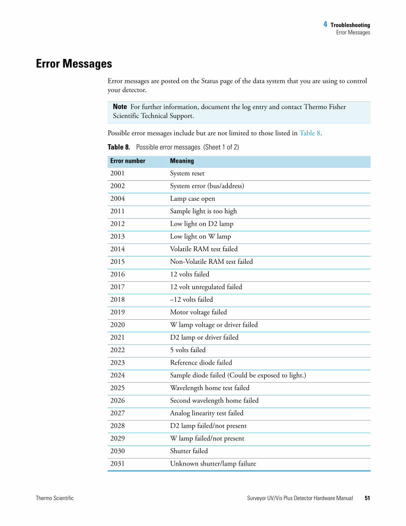
4 TroubleshootingError Messages
Error MessagesError messages are posted on the Status page of the data system that you are using to control your detector.
Possible error messages include but are not limited to those listed in Table 8.
Note For further information, document the log entry and contact Thermo Fisher Scientific Technical Support.
Table 8. Possible error messages (Sheet 1 of 2)
Error number Meaning
2001 System reset
2002 System error (bus/address)
2004 Lamp case open
2011 Sample light is too high
2012 Low light on D2 lamp
2013 Low light on W lamp
2014 Volatile RAM test failed
2015 Non-Volatile RAM test failed
2016 12 volts failed
2017 12 volt unregulated failed
2018 –12 volts failed
2019 Motor voltage failed
2020 W lamp voltage or driver failed
2021 D2 lamp or driver failed
2022 5 volts failed
2023 Reference diode failed
2024 Sample diode failed (Could be exposed to light.)
2025 Wavelength home test failed
2026 Second wavelength home failed
2027 Analog linearity test failed
2028 D2 lamp failed/not present
2029 W lamp failed/not present
2030 Shutter failed
2031 Unknown shutter/lamp failure
Thermo Scientific Surveyor UV/Vis Plus Detector Hardware Manual 51
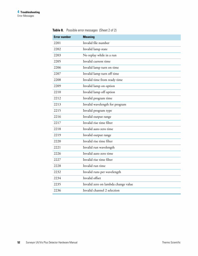
4 TroubleshootingError Messages
2201 Invalid file number
2202 Invalid lamp state
2203 No replay while in a run
2205 Invalid current time
2206 Invalid lamp turn on time
2207 Invalid lamp turn off time
2208 Invalid time from ready time
2209 Invalid lamp on option
2210 Invalid lamp off option
2212 Invalid program time
2213 Invalid wavelength for program
2215 Invalid program type
2216 Invalid output range
2217 Invalid rise time filter
2218 Invalid auto zero time
2219 Invalid output range
2220 Invalid rise time filter
2221 Invalid run wavelength
2226 Invalid auto zero time
2227 Invalid rise time filter
2228 Invalid run time
2232 Invalid runs per wavelength
2234 Invalid offset
2235 Invalid zero on lambda change value
2236 Invalid channel 2 selection
Table 8. Possible error messages (Sheet 2 of 2)
Error number Meaning
52 Surveyor UV/Vis Plus Detector Hardware Manual Thermo Scientific
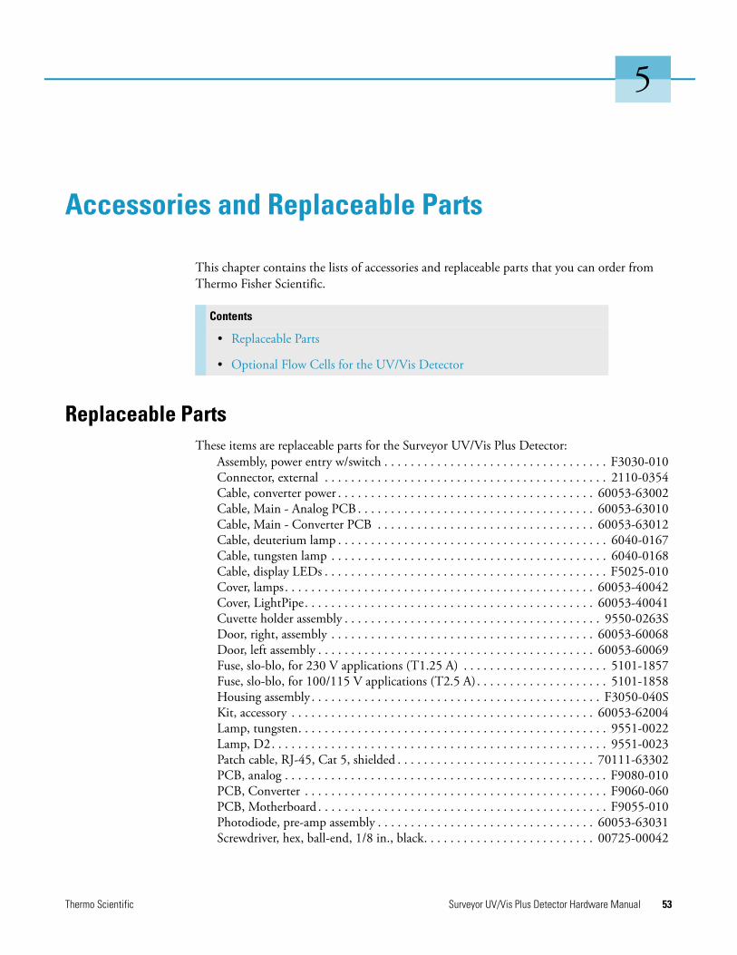
5
Accessories and Replaceable Parts
This chapter contains the lists of accessories and replaceable parts that you can order from Thermo Fisher Scientific.
Replaceable PartsThese items are replaceable parts for the Surveyor UV/Vis Plus Detector:
Assembly, power entry w/switch . . . . . . . . . . . . . . . . . . . . . . . . . . . . . . . . . . F3030-010Connector, external . . . . . . . . . . . . . . . . . . . . . . . . . . . . . . . . . . . . . . . . . . . 2110-0354Cable, converter power . . . . . . . . . . . . . . . . . . . . . . . . . . . . . . . . . . . . . . . 60053-63002Cable, Main - Analog PCB . . . . . . . . . . . . . . . . . . . . . . . . . . . . . . . . . . . . 60053-63010Cable, Main - Converter PCB . . . . . . . . . . . . . . . . . . . . . . . . . . . . . . . . . 60053-63012Cable, deuterium lamp . . . . . . . . . . . . . . . . . . . . . . . . . . . . . . . . . . . . . . . . . 6040-0167Cable, tungsten lamp . . . . . . . . . . . . . . . . . . . . . . . . . . . . . . . . . . . . . . . . . . 6040-0168Cable, display LEDs . . . . . . . . . . . . . . . . . . . . . . . . . . . . . . . . . . . . . . . . . . . F5025-010Cover, lamps. . . . . . . . . . . . . . . . . . . . . . . . . . . . . . . . . . . . . . . . . . . . . . . 60053-40042Cover, LightPipe. . . . . . . . . . . . . . . . . . . . . . . . . . . . . . . . . . . . . . . . . . . . 60053-40041Cuvette holder assembly . . . . . . . . . . . . . . . . . . . . . . . . . . . . . . . . . . . . . . . 9550-0263SDoor, right, assembly . . . . . . . . . . . . . . . . . . . . . . . . . . . . . . . . . . . . . . . . 60053-60068Door, left assembly . . . . . . . . . . . . . . . . . . . . . . . . . . . . . . . . . . . . . . . . . . 60053-60069Fuse, slo-blo, for 230 V applications (T1.25 A) . . . . . . . . . . . . . . . . . . . . . . 5101-1857Fuse, slo-blo, for 100/115 V applications (T2.5 A). . . . . . . . . . . . . . . . . . . . 5101-1858Housing assembly . . . . . . . . . . . . . . . . . . . . . . . . . . . . . . . . . . . . . . . . . . . . F3050-040SKit, accessory . . . . . . . . . . . . . . . . . . . . . . . . . . . . . . . . . . . . . . . . . . . . . . 60053-62004Lamp, tungsten. . . . . . . . . . . . . . . . . . . . . . . . . . . . . . . . . . . . . . . . . . . . . . . 9551-0022Lamp, D2. . . . . . . . . . . . . . . . . . . . . . . . . . . . . . . . . . . . . . . . . . . . . . . . . . . 9551-0023Patch cable, RJ-45, Cat 5, shielded . . . . . . . . . . . . . . . . . . . . . . . . . . . . . . 70111-63302PCB, analog . . . . . . . . . . . . . . . . . . . . . . . . . . . . . . . . . . . . . . . . . . . . . . . . . F9080-010PCB, Converter . . . . . . . . . . . . . . . . . . . . . . . . . . . . . . . . . . . . . . . . . . . . . . F9060-060PCB, Motherboard . . . . . . . . . . . . . . . . . . . . . . . . . . . . . . . . . . . . . . . . . . . . F9055-010Photodiode, pre-amp assembly . . . . . . . . . . . . . . . . . . . . . . . . . . . . . . . . . 60053-63031Screwdriver, hex, ball-end, 1/8 in., black. . . . . . . . . . . . . . . . . . . . . . . . . . 00725-00042
Contents
• Replaceable Parts
• Optional Flow Cells for the UV/Vis Detector
Thermo Scientific Surveyor UV/Vis Plus Detector Hardware Manual 53
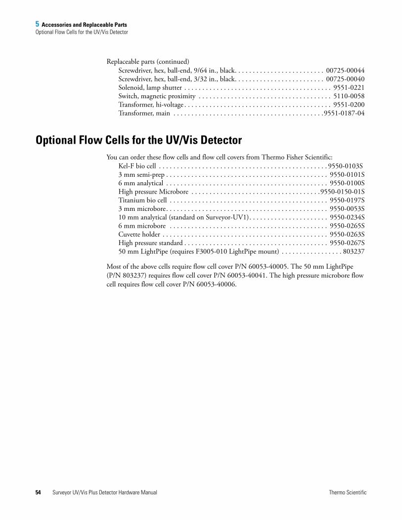
5 Accessories and Replaceable PartsOptional Flow Cells for the UV/Vis Detector
Replaceable parts (continued)Screwdriver, hex, ball-end, 9/64 in., black. . . . . . . . . . . . . . . . . . . . . . . . . 00725-00044Screwdriver, hex, ball-end, 3/32 in., black. . . . . . . . . . . . . . . . . . . . . . . . . 00725-00040Solenoid, lamp shutter . . . . . . . . . . . . . . . . . . . . . . . . . . . . . . . . . . . . . . . . . 9551-0221Switch, magnetic proximity . . . . . . . . . . . . . . . . . . . . . . . . . . . . . . . . . . . . . 5110-0058Transformer, hi-voltage . . . . . . . . . . . . . . . . . . . . . . . . . . . . . . . . . . . . . . . . . 9551-0200Transformer, main . . . . . . . . . . . . . . . . . . . . . . . . . . . . . . . . . . . . . . . . . .9551-0187-04
Optional Flow Cells for the UV/Vis DetectorYou can order these flow cells and flow cell covers from Thermo Fisher Scientific:
Kel-F bio cell . . . . . . . . . . . . . . . . . . . . . . . . . . . . . . . . . . . . . . . . . . . . . . . 9550-0103S 3 mm semi-prep . . . . . . . . . . . . . . . . . . . . . . . . . . . . . . . . . . . . . . . . . . . . . 9550-0101S6 mm analytical . . . . . . . . . . . . . . . . . . . . . . . . . . . . . . . . . . . . . . . . . . . . . 9550-0100SHigh pressure Microbore . . . . . . . . . . . . . . . . . . . . . . . . . . . . . . . . . . . .9550-0150-01STitanium bio cell . . . . . . . . . . . . . . . . . . . . . . . . . . . . . . . . . . . . . . . . . . . . 9550-0197S3 mm microbore. . . . . . . . . . . . . . . . . . . . . . . . . . . . . . . . . . . . . . . . . . . . . 9550-0053S10 mm analytical (standard on Surveyor-UV1). . . . . . . . . . . . . . . . . . . . . . 9550-0234S6 mm microbore . . . . . . . . . . . . . . . . . . . . . . . . . . . . . . . . . . . . . . . . . . . . 9550-0265SCuvette holder . . . . . . . . . . . . . . . . . . . . . . . . . . . . . . . . . . . . . . . . . . . . . . 9550-0263SHigh pressure standard . . . . . . . . . . . . . . . . . . . . . . . . . . . . . . . . . . . . . . . . 9550-0267S50 mm LightPipe (requires F3005-010 LightPipe mount) . . . . . . . . . . . . . . . . . 803237
Most of the above cells require flow cell cover P/N 60053-40005. The 50 mm LightPipe (P/N 803237) requires flow cell cover P/N 60053-40041. The high pressure microbore flow cell requires flow cell cover P/N 60053-40006.
54 Surveyor UV/Vis Plus Detector Hardware Manual Thermo Scientific

A
Surveyor Firmware Upgrade Utility
From time to time, upgrades to Surveyor UV/Vis Plus firmware might become available. If you need to upgrade the firmware or replace firmware that has become corrupted, you can do so by using the Surveyor Firmware Upgrade Utility. This appendix provides instructions on how to use the Surveyor Firmware Upgrade Utility.
To download firmware using the Surveyor Firmware Upgrade Utility
1. From Windows™ Explorer locate the firmware files you intend to download:
• For the ChromQuest™ data system, these files are located in the Firmware folder on the ChromQuest CD.
• For the Xcalibur ™data system, these files are located in the following folder:
drive:\Xcalibur\system\Surveyor Firmware
2. Set the Unit ID on the detector’s back panel to the maintenance setting as follows:
a. Ensure that the UV/Vis power is turned off.
b. Make a note of the current settings of the rotary switches on the back of the UV/Vis detector. You will return them to these positions at the conclusion of the procedure.
c. Set the switches of the UV/Vis to 00.
3. Ensure that your Surveyor UV/Vis Plus Detector is connected to your data system computer with the standard Ethernet connection.
4. Turn the power to the detector on.
The COMM LED blinks amber to confirm that the Surveyor UV/Vis Plus Detector is configured for downloading the firmware.
5. Start the Surveyor Firmware Upgrade Utility by double-clicking the Surveyor Firmware Upgrade Utility application. The Surveyor Firmware Upgrade Utility window opens. See Figure 36.
Thermo Scientific Surveyor UV/Vis Plus Detector Hardware Manual 55
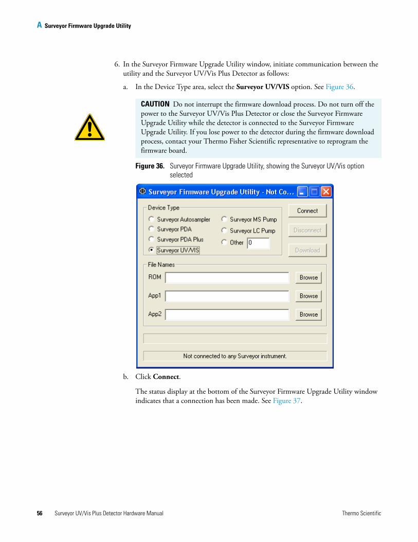
A Surveyor Firmware Upgrade Utility
6. In the Surveyor Firmware Upgrade Utility window, initiate communication between the utility and the Surveyor UV/Vis Plus Detector as follows:
a. In the Device Type area, select the Surveyor UV/VIS option. See Figure 36.
Figure 36. Surveyor Firmware Upgrade Utility, showing the Surveyor UV/Vis option selected
b. Click Connect.
The status display at the bottom of the Surveyor Firmware Upgrade Utility window indicates that a connection has been made. See Figure 37.
CAUTION Do not interrupt the firmware download process. Do not turn off the power to the Surveyor UV/Vis Plus Detector or close the Surveyor Firmware Upgrade Utility while the detector is connected to the Surveyor Firmware Upgrade Utility. If you lose power to the detector during the firmware download process, contact your Thermo Fisher Scientific representative to reprogram the firmware board.
56 Surveyor UV/Vis Plus Detector Hardware Manual Thermo Scientific

A Surveyor Firmware Upgrade Utility
Figure 37. Surveyor Firmware Upgrade Utility showing a successful connection to the Surveyor UV/Vis Plus Detector
7. In the File Names area, select the appropriate firmware files for the Surveyor UV/Vis Detector as follows:
a. Click Browse to the right of the ROM box, and then select the ROM 1.0.8.bin file.
The file name appears in the ROM box. See Figure 37.
b. Click Browse to the right of the APP1 box, and then select the APP1_UVVis_1.10.bin file.
The file name appears in the App1 box. See Figure 37.
8. Click Download, and wait for the download to finish.
The utility notifies you when it completes the download (see Figure 38). Once the download is complete, you can safely close the Surveyor Firmware Upgrade Utility and turn off the power to the detector.
IMPORTANT You must select both a ROM file and an APP1 file. Your Surveyor UV/Vis Plus Detector will not work properly if you do not download these files together.
Thermo Scientific Surveyor UV/Vis Plus Detector Hardware Manual 57
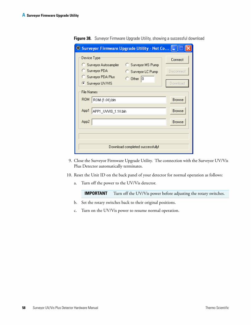
A Surveyor Firmware Upgrade Utility
Figure 38. Surveyor Firmware Upgrade Utility, showing a successful download
9. Close the Surveyor Firmware Upgrade Utility. The connection with the Surveyor UV/Vis Plus Detector automatically terminates.
10. Reset the Unit ID on the back panel of your detector for normal operation as follows:
a. Turn off the power to the UV/Vis detector.
b. Set the rotary switches back to their original positions.
c. Turn on the UV/Vis power to resume normal operation.
IMPORTANT Turn off the UV/Vis power before adjusting the rotary switches.
58 Surveyor UV/Vis Plus Detector Hardware Manual Thermo Scientific
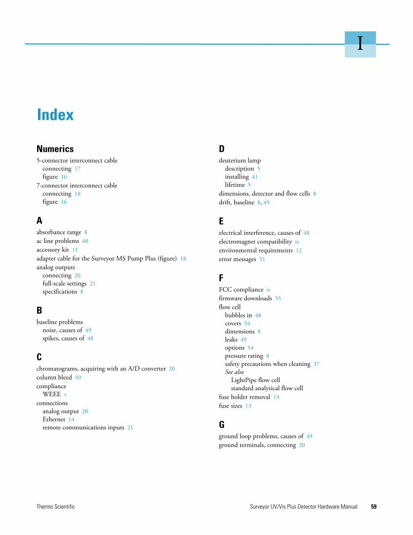
I
Index
Numerics5-connector interconnect cable
connecting 17figure 16
7-connector interconnect cableconnecting 18figure 16
Aabsorbance range 8ac line problems 48accessory kit 11adapter cable for the Surveyor MS Pump Plus (figure) 18analog outputs
connecting 20full-scale settings 21specifications 8
Bbaseline problems
noise, causes of 49spikes, causes of 48
Cchromatograms, acquiring with an A/D converter 20column bleed 49compliance
WEEE vconnections
analog output 20Ethernet 14remote communications inputs 21
Ddeuterium lamp
description 5installing 41lifetime 5
dimensions, detector and flow cells 8drift, baseline 8, 49
Eelectrical interference, causes of 48electromagnet compatibility ivenvironmental requirements 12error messages 51
FFCC compliance ivfirmware downloads 55flow cell
bubbles in 48covers 54dimensions 8leaks 49options 54pressure rating 8safety precautions when cleaning 37See also
LightPipe flow cellstandard analytical flow cell
fuse holder removal 13fuse sizes 13
Gground loop problems, causes of 49ground terminals, connecting 20
Thermo Scientific Surveyor UV/Vis Plus Detector Hardware Manual 59
Index: I
Iinitial power on 24installation
accessory kit 11checklist 10LightPipe flow cell 31powering on 24shipping container, unpacking 11standard analytical flow cell 35tools for 12
Llamp cover 39lamps
replacing 38See also
deuterium lamptungsten lamp
useful lifetime 5LEDs, meaning 7LightPipe flow cell
cleaning 36installing 31ready for storage 30removing 27schematic, 50 mm Light Pipe 3
linearity 8
Mmaintenance
cleaning external surfaces 27preventive 26recommendations for 26standard analytical flow cell, removing 33
maintenance tools 27
Nnitric acid, safety precautions 37noise, causes of 49
Ooperating environment
humidity 8temperature 8
optical bench (figure) 2optical fiber (figure) 4
Pparts, replaceable 53peak problems
broadening 50size 50tailing 50
photodiode mount (figure) 34power requirements 8
Rregulatory compliance iiiremote controls 8rise time
incorrect setting, results of 50settings 8
Ssafety standards iiiscan rate 8short term noise 8specifications, detector 8spectral bandwidth 8standard analytical flow cell
cover (figure) 33installing 35removing 33
storage temperature 8Surveyor Firmware Upgrade Utility 55
Ttemperature fluctuations, results of 49tools
needed for installation 12needed for maintenance 27
troubleshootingdetector problems 48Status page error messages 51
tungsten lampdescription 5installing 45lifetime 5, 38removing 43
Uuninterruptible power supply (UPS) 48unit ID, setting 15unpacking your detector 11
60 Surveyor UV/Vis Plus Detector Hardware Manual Thermo Scientific
Index: V
Vvoltage
ac line problems 48setting, changing 13voltage selector (figure) 13
Wwarm-up time 8wavelength
accuracy 8range 8
WEEE compliance vweight, detector 8
Thermo Scientific Surveyor UV/Vis Plus Detector Hardware Manual 61


