CellASIC ONIX™ System Setup Guide 1. System Components 2. Required Equipment 3. System Set-Up 4. CO2 Calibration 5. Temperature Calibration 7. Microscope Set-Up 8. Microincubation 9. Software 10. Culture and Image Cells Software ONIX Flow System and Manifold CO2 sensor Bioptechs Inc. Objective Heater and Controller Select Caution! -Do not remove the heater from the objective if the controller is on. - Always press [Alarm Reset] before plugging the heater into the controller. -Plug the heater in to the controller after the heater is installed onto the objective. Made in U.S.A. Alarm Reset Setpoint Objective Reference BIOPTECH Objective Heater Controller BIOPTECHS Temperature Calibration Plate 1. System Components The CellASIC ONIX™ platform is sold with the components displayed above.
Transcript
CellASIC ONIX™ System Setup Guide
1. System Components2. Required Equipment3. System Set-Up4. CO2 Calibration5. Temperature Calibration
7. Microscope Set-Up8. Microincubation9. Software10. Culture and Image Cells
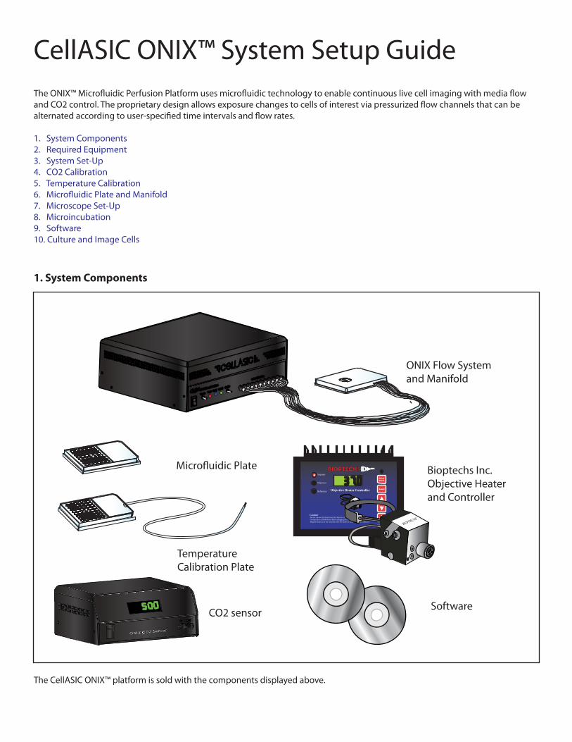
Software
ONIX Flow System and Manifold
CO2 sensor
Bioptechs Inc.Objective Heater and Controller
Select
BIOPTECHS
Caution!-Do not remove the heater from the objective if the controller is on.- Always press [Alarm Reset] before plugging the heater into the controller.-Plug the heater in to the controller after the heater is installed onto the objective.
Made in U.S.A.
AlarmReset
Setpoint
Objective
Reference
BIOPTECH
Objective Heater Controller
BIOPTECHS
Temperature Calibration Plate
1. System Components
The CellASIC ONIX™ platform is sold with the components displayed above.
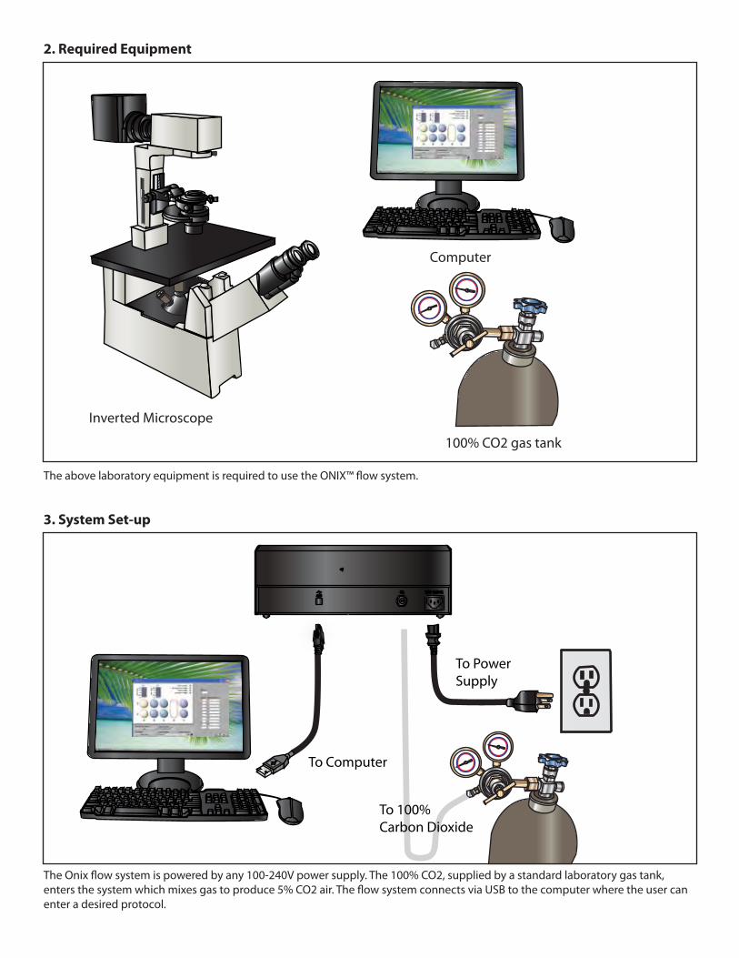
100% CO2 gas tank
Inverted Microscope
Computer
2. Required Equipment
To Power Supply
To Computer
To 100%Carbon Dioxide
3. System Set-up
enter a desired protocol.
4. CO2 Calibration
5. Temperature Calibration
Optional: If the user wishes to monitor the CO2 levels during an experiment, the CO2 sensor output can be connected to the manifold with the provided tubing.
The temperature calibration plate plugs into the objective heater controller. Its unique design allows for precise temperature calibration of the cell culture chamber.
1. Ensure the CO2 source is between 10-40 psi...
... and connected to rear input of the ONIX �ow system.
2. Connect tubing adaptor input from CO2 sensor input into leftmost Leur �tting on system.
3. Power on ONIX system and �ip on CO2/Air switch.
4. Check display for CO2 percentage. Use a small �athead screwdriver to adjust CO2 regulator on the back of the system to desired output.
6. Adjust Setpoint to obtain desired temperature.
2. Seal manifold to temperature calibration plate.
3. Place plate on microscope while threading thermistor cord under the stage.
1. Mount Objective Heater and add a drop of immersion oil to the objective.
4. Find and focus on culture chamber with microscope.
5. Connect thermistor cord to reference socket on heater controller.
6. Micro�uidic Plate and Manifold
7. Microscope Set-Up
Place the Bioptechs objective heater onto the objective lens. Plug the heater ino the heater controller to view set temperature.The objective heater maintains a stable temperature throughout the duration of your experiment. Place plate and manifold together onto the microscope stage for live cell imaging.
The manifold delivers both positive and negative pressures to each well to control �uid �ow through the cell chamber. It also provides a sterile environment for the cells and serves as a conduit for CO2 delivery.
1. Attach manifold to ONIX system with Luer �ttings.
5. Push down on manifold.
2. Pipette solutions into microfluidic plate.
4. Flip Vacuum switch on.
3. Align manifold cover with plate.
6. Sealed light will turn on indicating proper closure.
Push Down
To ONIX Flow System
To Bioptechs Inc. Objective Heater Controller
Objective Heater
Manifold Cover and Microfluidic Plate
5% CO2
Heated objective lens
Glass coverslip
Manifold
Cells at 37˚
top view
side
vie
w
Program Timer
Status IndicatorsFlow Rate Setting
Individual WellControls
8. Microincubation
-ture.
9. Software
ONIX FG software program automates your perfusion protocol for automated solution switching. The program allows the user to
10. Culture and Image Cells
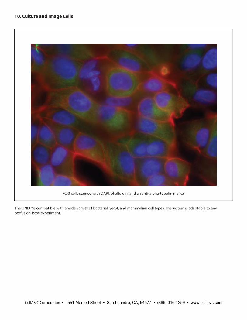
The ONIX™is compatible with a wide variety of bacterial, yeast, and mammalian cell types. The system is adaptable to any perfusion-base experiment.
PC-3 cells stained with DAPI, phalloidin, and an anti-alpha-tubulin marker
CellASIC Corporation • 2551 Merced Street • San Leandro, CA, 94577 • (866) 316-1259 • www.cellasic.com