Cellulose Fibers and Microcellular Foam Starch Composites Richard A. Venditti*, Joel J. Pawlak, Andrew R. Rutledge, Janderson L. Cibils Forest Biomaterials Science and Engineering NC State University, Raleigh, NC
Transcript
Cellulose Fibers and Microcellular Foam Starch Composites
Richard A. Venditti*, Joel J. Pawlak, Andrew R. Rutledge, Janderson L. Cibils
Forest Biomaterials Science and Engineering NC State University, Raleigh, NC
Outline
• Introduction to Starch Microcellular Foams• Objective• Procedures• Results and Discussion• Conclusions• Further Work• Acknowledgements
Microcellular Starch Foams• SMCF production methods
(avoids drying from high surface tension liquids)
– Freeze Drying – rapid freezing, many nucleating sites
– Multiple Solvent exchange• Example: 8% aqueous solution of
– Venditti and Pawlak and coworkers, 2007 and 2008.
The pressure exerted on the plates separated by a 0.01 micron layer of water is approximately 142 atmospheres.
δ
Laplace Equation simplified for liquid between 2 plates.
water P1 P2
δγ2
12 =−=Δ PPP
Cell wall
Cell wall
Pore Preserving Drying
Starch AquagelDried from Ethanol
Dried from Water
Microcellular Foam
SEM of Uncooked Starch and SMCF
7.5g glutaraldehyde / 100g starch Length scale is 20 microns
Uncooked Starch
80
90
100
0 5 10 15 20 25 30 35
Glutaraldehyde, %
Bri
ghtn
ess
(ISO
)
Microcellular Starch Foams• Microcellular starch foams: a starch based
porous matrix containing pores ranging from 2 micrometers to sub-micrometer size
• Cell densities > 109 cells per cm3 • Specific density reduction of 5 to 98% of
matrix material• SMCF materials have high specific surface
areas (air-solid interfaces). – SMCF from CO2: 50-150 m2/g– Calcium Carbonate: 2-6 m2/g– TiO2: 8-25 m2/g
• Coatings and filler particles made from microcellular foams are expected to be excellent in their ability to scatter light and be strong opacifying materials
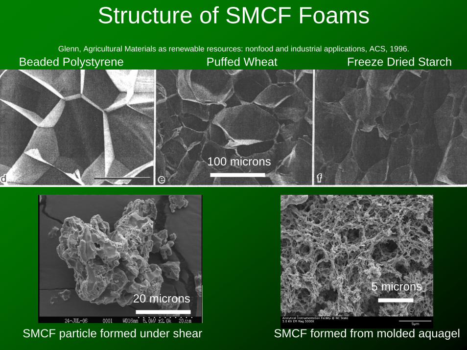
Micrographs of SMCF created by freeze drying starch (top) and starch/AKD(middle) Also shown is SMCF created by solvent exchange (bottom).
B
B
C
Structure of SMCF FoamsGlenn, Agricultural Materials as renewable resources: nonfood and industrial applications, ACS, 1996.
properties of the foams• Increased amylose improved the shape
smoothness of the molded parts• Increased amylose increased the density of
molded parts• Increased fiber content up to 5% improved the
structure (decreased density) and toughness• Above 5% fiber content the foams were had an
uneven distribution of fibers
Composition Effects
• Increased fiber content up to 5% improved the structure (decreased density) and toughness
• Above 5% fiber content the foams had an uneven distribution of fibers
Procedures: Mechanical ProptsCompression testing on a MTS Model Alliance RF300 with 60,000 lb
frame and 260 lb Omega load cell. Strain rate of 0.5 mm/min.
Heat Treatment/Carbonization of SMCF-Fiber Composites
• Heat treatment at 200 C produces a wood-like foam material of low density (0.45 g/cc)
• Produces a low density (0.20 g/cc) porous carbon microstructure
• Inert, strong, low density (0.20 g/cc) foam upon heating to 350 C and above
200 C Untreated 350 C
TGA Results: 50% Amylose with Fiber
Starch
Fiber
Effect of Treatment Temperature on Yield:SMCF-Fiber Composites
0
20
40
60
80
100
120
0 200 400 600 800
Temperature, C
Yield, %
Effect of Treatment Temperature on Density:SMCF-Fiber Composites
0.00
0.10
0.20
0.30
0.40
0.50
0.60
0 200 400 600 800
Temperature, C
Den
sity, g/cc
Dimensional Changes vs Treatment Temperature:SMCF-Fiber Composites
‐20
‐10
0
10
20
30
40
1 2 3 4 5
Temperature, C
Shrink
age, % X-Y Plane
Z-Direction
Compression Testing Results
0
1 0 0
2 0 0
3 0 0
4 0 0
0 1 2 3 4
O m e g a L o a d c e ll ( N )
C r o s s h e a d ( m m )
[ 3 ]S
P
B
M
0
1 0
2 0
3 0
4 0
5 0
6 0
7 0
8 0
9 0
0 . 0 1 . 0 2 . 0 3 . 0
O m e g a L o a d c e ll ( N )
C r o s s h e a d ( m m )
[ 1 1 ]
S
P
Y
B
M
Typical results for untreated and treated at 200 C.
(Note Y-axis max is 400 N)
Typical results for 350 C and higher treatment temperatures.
(Note Y-axis max is 90 N)
Effect of Treatment Temperature on Mechanical Properties:
Increases in viscosity improve pore structure and brightness.
Effect of Treatment Temperature on Weight NormalizedMechanical
Properties:
Increases in viscosity improve pore structure and brightness.
Results from study:• Particles with a fine porous structure and high
brightness can be formed with the described solvent exchange method
• Crosslinking/Molecular weight found to improve pore structure and optical properties
• The resulting SMCF particles absorbed water rapidly and lost structure upon wetting
• Water resistance must be increased
Challenges
• The major challenge still remains to control the wetting properties of the SMCF
• Blending, derivatization and crosslinkingare being explored as approaches to development of water resistance
• Alternative methods of foam formation including carbon dioxide assisted extrusion are also being explored to modify pore structure
This research is supported by National Research Initiative Competitive Grant 2005-35504-16264 from the USDA Cooperative State Research, Education, and Extension Service
Support was also provided by the NCSU and College of Natural Resources Undergraduate Research Program.